1
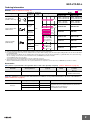
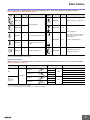
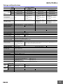
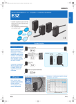
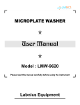
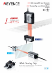
Compact Laser Photoelectric Sensor with Built-in Amplifier
E3Z-LT/LR/LL
CSM_E3Z-LT_LR_LL_DS_E_6_4
Compact and Reliable
Laser Photoelectric Sensor
• Safety and reliability with laser class 1 (JIS and IEC).
• Product lineup includes models with distance setting without influence of
color.
• Maximum ambient operating temperature of 55°C and water-proof
construction in E3Z class.
Be sure to read Safety Precautions on
page 9.
Applications
Detect the sides of large tiles.
Greatly Enhanced Beam Visibility
for Easier Optical Axis Adjustment of Sensors
Detect chip components on tape.
Long-distance Sensing
at 300 mm (White Paper)
Count bottles.
Reliable Detection of
Small Objects and
Narrow Gaps with the Small Spot
Detect protruding straws.
A Low Black/White Error for
Applications with Mixed Colors
1
E3Z-LT/LR/LL
Ordering Information
Sensors
(Refer to Dimensions on page 11.)
Sensing method
Appearance
Connection
method
Red light
Response
time
Sensing distance
Pre-wired
(2 m)*3
Through-beam
(Emitter + Receiver) *4
60 m
Connector
(M8, 4 pins)
Model
NPN output
E3Z-LT61 2M
Emitter E3Z-T61-L 2M
Receiver E3Z-T61-D 2M
E3Z-LT66
Emitter E3Z-T66-L
Receiver E3Z-T66-D
PNP output
E3Z-LT81 2M
Emitter E3Z-T81-L 2M
Receiver E3Z-T81-D 2M
E3Z-LT86
Emitter E3Z-T86-L
Receiver E3Z-T86-D
E3Z-LR61 2M
E3Z-LR81 2M
E3Z-LR66
E3Z-LR86
E3Z-LL61 2M
E3Z-LL81 2M
E3Z-LL66
E3Z-LL86
E3Z-LL63 2M
E3Z-LL83 2M
E3Z-LL68
E3Z-LL88
*2
Pre-wired
(2 m)*3
Retro-reflective with
MSR function
15 m
1 ms
*1
7m
(Using E39-R12)
Connector
(M8, 4 pins)
(200 mm)
7m
(Using E39-R6)
Pre-wired
(2 m)*3
(200 mm)
20 to 40 mm
(Min. distance set)
20 to 300 mm
Connector
(M8, 4 pins)
Distance-settable
(BGS Models)
(300 mm)
(Using E39-R1)
(Max. distance set)
Pre-wired
(2 m)*3
25 to 40 mm
0.5 ms
Connector
(M8, 4 pins)
(Min. distance set)
25 to 300 mm
(Max. distance set)
*1. The Reflector is sold separately. Select the Reflector model most suited to the application.
*2. Values in parentheses indicate the minimum required distance between the Sensor and Reflector.
*3. Pre-wired Models with a 0.5-m cable are also available for these products. When ordering, specify the cable length by adding “0.5M” to the end of the model number
(e.g., E3Z-LT61 0.5M).
M12 Pre-wired Connector Models are also available. When ordering, add “-M1J” to the end of the model number (e.g., E3Z-LT61-M1J). The cable is 0.3 m long.
Also, the following connection forms can be manufactured. Ask your OMRON representative for details.
• Pre-wired Models with 1-m or 5-m cables
• Pre-wired Connector Models with M8 4-pin connectors or M8 3-pin connectors.
*4. Through-beam Sensors are normally sold in sets that include both the Emitter and Receiver.
Orders for individual Emitters and Receivers are accepted. (Modifications are required for some models. Ask your OMRON representative for details.)
Accessories
Slits (A Slit is not provided with a Through-beam Sensor. Order a Slit separately if required.) (Refer to Dimensions on page 14.)
Slit width
Sensing distance
Minimum detectable object
(typical)
Model
Contents
0.5 mm dia.
3m
0.1 mm dia.
E39-S65A
One set
(contains Slits for both the
Emitter and Receiver)
Reflectors (A Reflector is required for Retro-reflective Sensors: A Reflector is not provided with the Sensor. Be sure to order a Reflector.)
(Refer to Dimensions on page 14.)
Name
Reflector
Sensing distance (typical)
Model
15 m (300 mm)
E39-R1
7 m (200 mm)
E39-R12
7 m (200 mm)
E39-R6
Remarks
• Retro-reflective models are not provided with Reflectors.
• Separate the Sensor and the Reflector by at least the
distance given in parentheses.
• The MSR function is enabled.
2
E3Z-LT/LR/LL
Mounting Brackets A Mounting Bracket is not provided with the Sensor. Order a Mounting Bracket separately if required.
(Refer to Dimensions on E39-L/F39-L/E39-S/E39-R.)
Appearance
Model
Quantity
E39-L153
1
Remarks
Appearance
Model
Quantity
Remarks
E39-L98
1
Metal Protective Cover Bracket *
E39-L150
1 set
Mounting Brackets
E39-L104
1
(Sensor adjuster)
E39-L43
1
Easily mounted to the aluminum
frame rails of conveyors and
easily adjusted.
Horizontal Mounting Bracket *
E39-L142
1
Horizontal Protective Cover
Bracket *
E39-L44
1
Rear Mounting Bracket
E39-L151
1 set
For left to right adjustment
E39-L144
1
Compact Protective Cover
Bracket (For E3Z only) *
Note: When using a Through-beam Sensor, order one Mounting Bracket for the Receiver and one for the Emitter
* Cannot be used for Standard Connector models.
Sensor I/O Connectors
(Models for Connectors and Pre-wired Connectors: A Connector is not provided with the Sensor. Be sure to order a Connector separately.)
(Refer to Dimensions on XS3, XS2)
Size
Cable
Appearance
Straight *1
2m
5m
M8
L-shaped *1 *2
Standard
M12
(For -M1J
models)
Cable type
Straight *1
2m
XS3F-M421-402-A
4-wire
XS3F-M421-405-A
XS3F-M422-402-A
5m
XS3F-M422-405-A
2m
XS2F-D421-DC0-A
5m
L-shaped *1
Model
3-wire
XS2F-D421-GC0-A
2m
XS2F-D422-DC0-A
5m
XS2F-D422-GC0-A
Note: When using a Through-beam Sensor, order one Mounting Bracket for the Receiver and one for the Emitter
*1. The connector will not rotate after connecting.
*2. The cable is fixed at an angle of 180° from the sensor emitter/receiver surface.
3
E3Z-LT/LR/LL
Ratings and Specifications
Sensing
method
Retro-reflective with MSR
function
Through-beam
Response
Model
Item
Distance-settable (BGS models)
Standard response
High-speed response
NPN
output
E3Z-LT61/-LT66
E3Z-LR61/-LR66
E3Z-LL61/-LL66
E3Z-LL63/-LL68
PNP
output
E3Z-LT81/-LT86
E3Z-LR81/-LR86
E3Z-LL81/-LL86
E3Z-LL83/-LL88
Sensing distance
0.3 to 15 m
(when using E39-R1)
0.2 to 7 m
(when using E39-R12)
0.2 to 7 m
(when using E39-R6)
60 m
Set distance range
---
Spot diameter (typical)
5-mm dia. at 3 m
Standard sensing object
Opaque: 12-mm dia. min.
Minimum detectable
object (typical)
6-mm-dia. opaque object at 3 m
White paper (100 × 100 mm):
20 to 300 mm
Black paper (100 × 100 mm):
20 to 160 mm
White paper (100 × 100 mm):
25 to 300 mm
Black paper (100 × 100 mm):
25 to 100 mm
White paper (100 × 100 mm):
40 to 300 mm
Black paper (100 × 100 mm):
40 to 160 mm
White paper (100 × 100 mm):
40 to 300 mm
Black paper (100 × 100 mm):
40 to 100 mm
0.5-mm dia. at 300 mm
Opaque: 75-mm dia. min.
--0.2-mm-dia. stainless-steel pin gauge at 300 mm
Differential travel
---
5% max. of set distance
Black/white error
---
5% at 160 mm
5% at 100 mm
Directional angle
Receiver: 3 to 15°
Light source (wavelength)
Red LD (655 nm), JIS CLass 1, IEC Class 1, FDA Class II
Power supply voltage
12 to 24 VDC±10%, ripple (p-p): 10% max.
Current consumption
35 mA (Emitter 15 mA,
Receiver 20 mA)
Control output
Load power supply voltage: 26.4 VDC max., Load current: 100 mA max., Open collector output
Residual output voltage
Load current of less than 10 mA: 1 V max.
Load current of 10 to 100 mA: 2 V max.
Output mode switching
Switch to change between light-ON and dark-ON
Protection circuits
Reversed power supply
polarity protection, Output
short-circuit protection, and
Reversed output polarity
protection
Response time
Operate or reset: 1 ms max.
Sensitivity adjustment
One-turn adjuster
Ambient illumination
(Receiver side)
Incandescent lamp: 3,000 lx max.
Sunlight: 10,000 lx max.
Ambient temperature range
Operating: −10 to 55°C, Storage: −25 to 70°C (with no icing or condensation)
Ambient humidity range
Operating: 35% to 85%, Storage: 35% to 95% (with no icing or condensation)
Insulation resistance
20 MΩ min. at 500 VDC
Dielectric strength
1,000 VAC, 50/60 Hz for 1 min
Vibration resistance
Destruction: 10 to 55 Hz, 1.5-mm double amplitude for 2 hours each in X, Y, and Z directions
Shock resistance
Destruction: 500 m/s2 3 times each in X, Y, and Z directions
Degree of protection
IP67 (IEC 60529)
Connection method
Pre-wired cable (standard length: 2 m):
Standard M8 Connector:
Indicator
Operation indicator (orange)
Stability indicator (green)
Emitter for Through-bream Models has power indicator (orange) only.
Weight
(packed
state)
Material
---
30 mA max.
Reversed power supply polarity protection, Output short-circuit protection, Mutual interference prevention, and Reversed output polarity protection
Operate or reset: 0.5 ms max.
Five-turn endless adjuster
Pre-wired cable
(2 m)
Approx. 120 g
Approx. 65 g
Standard
Connector
Approx. 30 g
Approx. 20 g
Case
PBT (polybutylene terephthalate)
Lens
Accessories
Modified polyarylate resin
E3Z-L@@1/-L@@3
E3Z-L@@6/-L@@8
Methacrylic resin
Modified polyarylate resin
Instruction manual (Neither Reflectors nor Mounting Brackets are provided with any of the above models.)
4
E3Z-LT/LR/LL
Engineering Data (Typical)
Through-beam Models
E3Z-LT@@ + E39-S65A
150
100
Retro-reflective Models
E3Z-LR@@
20
Distance Y (mm)
Distance (mm)
Distance Y (mm)
Parallel Operating Range
Through-beam Models
E3Z-LT@@
15
10
50
5
0
20
40
60
0
80
2
4
6
8
10
−5
−50
60
E39-R1
Y
40
20
0
−10
−20
Y
Sensing object:
100 × 100 mm
white paper
1.50
X
1.00
0.50
0.00
0
50
100
150
200
30
Distance X (m)
3
2
Y
Sensing object:
100 × 100 mm
white paper
1
X
0
350
250
−0.50
25
Operating Range at a Set Distance
of 40 mm
BGS Models
E3Z-LL@@
Operating range Y (mm)
Operating range Y (mm)
2.00
20
−60
Distance (m)
Distance X (m)
2.50
15
−40
−15
Operating Range at a Set Distance
of 300 mm
BGS Models
E3Z-LL@@
10
E39-R12
X
−150
5
−20
Y
−100
X
E39-R6
10
20
30
40
50
60
300
−1
−1.00
−1.50
−2
−2.00
−2.50
−3
Distance X (mm)
Distance X (mm)
10000
Retro-reflective Models
E3Z-LR@@
Excess gain ratio (multiple)
Excess gain ratio (multiple)
Excess Gain vs. Set Distance
Through-beam Models
E3Z-LT@@
1000
100
E39-R1
10
E39-R12
1
E39-R6
100
0
10
20
30
40
50
60
70
0.1
80
0
10
20
30
Distance (m)
350
300
E3Z-LL@3/-LL@8
Sensing distance (mm)
Sensing distance (mm)
Close Range Characteristics
BGS Models
E3Z-LL@1/-LL@6
Distance (m)
300 mm
250
200
350
300
300 mm
250
200
160 mm
150
150
100
100
40 mm
50
0
10 mm
White
paper
Setting:
300 mm
12 mm
Black
paper
Setting:
160 mm
0 mm
White
paper
Setting:
40 mm
40 mm
9 mm
Black
paper
Setting:
40 mm
100 mm
40 mm
50
10 mm
0
White
paper
Setting:
300 mm
21 mm
Black
paper
Setting:
100 mm
White
paper
Setting:
40 mm
0 mm
40 mm
9 mm
Black
paper
Setting:
40 mm
5
E3Z-LT/LR/LL
Sensing Distance vs. Sensing Object Material
BGS Models
E3Z-LL@3/-LL@8
E3Z-LL@1/-LL@6
50
Sensing distance (mm)
50
40
30
E3Z-LL@1/-LL@6
White Paper with a Set Distance of 40 mm
White Paper with a Set Distance of 300 mm
Sensing distance (mm)
Sensing distance (mm)
White Paper with a Set Distance of 40 mm
40
30
350
300
250
200
150
20
20
100
10
10
0
White Veneer Card- Black Black SUS
paper
board paper rubber
Material
E3Z-LL@3/-LL@8
120
100
80
White Veneer Card- Black Black SUS
paper
board paper rubber
Mirror
surface
Material
Mirror
surface
Material
Emission Spot Diameter vs. Distance
Through-beam and Retro-reflective
Models (Same for All Models)
BGS Models (Same for All Models)
E3Z-LT@@, E3Z-LR@@
E3Z-LL@@
100
Spot diameter (mm)
Sensing distance (mm)
White Paper with a Set Distance of 100 mm
0
0
Mirror
surface
90
Spot diameter (mm)
White Veneer Card- Black Black SUS
paper
board paper rubber
50
a
80
b
70
Spot shape
60
Dimension a
1.0
Dimension a
40
40
1.2
0.8
50
60
1.4
30
20
0.6
Dimension b
0.4
a
Dimension b
b
0.2
20
10
Spot shape
0
0
White
paper
Veneer
Cardboard
Black
paper
Black
rubber
SUS
0
0
Mirror
surface
10
20
30
40
50
60
Set distance (m)
0
100
200
300
400
500
600
Set distance (mm)
Material
E3Z-LL@3 (LL@8)
2.50
Hysteresis (%)
Hysteresis (%)
Hysteresis vs. Distance
BGS Models
E3Z-LL@1 (LL@6)
2.00
Black
paper
1.50
2.50
2.00
Black
paper
1.50
1.00
1.00
White
paper
White
paper
0.50
0.50
0.00
0.00
0
100
200
300
400
0
100
200
300
Set distance (mm)
20
Distance setting: 300 mm
Sensing object: White paper
100 × 100 mm
15
10
5
0
(Upwards
and
Downwards)
Inclination
angle
−5
−10
Inclination Characteristics (Horizontal)
BGS Models
E3Z-LL@@
Sensing distance variation (%)
Sensing distance variation (%)
Inclination Characteristics (Vertical)
BGS Models
E3Z-LL@@
20
15
5
0
−5
−10
Sensing
object
−20
−40
−30
Center
line
−20
−10
−15
−θ
0
10
20
30
40
Inclination angle θ (°)
Distance setting: 300 mm
Sensing object: White paper
100 × 100 mm
10
+θ
−15
400
Set distance (mm)
(Left and
Right)
Inclination
angle
+θ
−θ
Sensing Center
object line
−20
−40 −30 −20 −10
0
10
20
30
40
Inclination angle θ (°)
6
E3Z-LT/LR/LL
I/O Circuit Diagrams
NPN Output
Model
E3Z-LT61 *
E3Z-LT66 *
E3Z-LR61
E3Z-LR66
Operation
mode
Timing charts
Light-ON
Light incident
Light interrupted
Operation indicator ON
(orange)
OFF
ON
Output transistor
OFF
Load
Operate
(e.g., relay)
Reset
(Between brown and black leads)
Dark-ON
Operation
selector
Light incident
Light interrupted
Operation indicator ON
(orange)
OFF
ON
Output transistor
OFF
Load
Operate
(e.g., relay)
Reset
(Between brown and black leads)
Through-beam Receivers, Retro-reflective Models
D side
(DARK ON)
(Control
output)
Black
ZD
Blue
3
M12 Connector
Pin Arrangement
M8 4-pin Connector
Pin Arrangement
1
2
2
M8 3-pin Connector
Pin Arrangement
4
4
1
4
3
1
3
Pin 2 is not used.
M12 Connector
Pin Arrangement
2
M8 3-pin Connector
Pin Arrangement
M8 4-pin Connector
Pin Arrangement
1
2
4
4
1
4
1
3
3
3
Blue
Pins 2 and 4
are not used.
FAR
12 to 24 VDC
Brown
Operation
ON
indicator
(orange)
OFF
ON
Output
transistor
OFF
Load
Operate
(e.g., relay) Reset
(Between brown and black leads)
Load
(Relay)
100 mA
max.
4
3
L side
(LIGHT ON)
NEAR FAR
Operation
indicator
ON
(orange)
OFF
Output
ON
transistor
OFF
Load
Operate
(e.g., relay) Reset
(Between brown and black leads)
D side
(DARK ON)
Operation
mode
Timing charts
Operation
selector
Light-ON
Light incident
Light interrupted
Operation indicator ON
(orange)
OFF
ON
Output transistor
OFF
Load
Operate
(e.g., relay)
Reset
(Between blue and black leads)
Dark-ON
(Orange)
12 to 24 VDC
NEAR
E3Z-LL61
E3Z-LL66
E3Z-LL63
E3Z-LL68
1
Stability
indicator
(Green)
0V
Brown
3
Light-ON
Operation
indicator
Photoelectric
Sensor
Main
Circuit
1
Photoelectric
Sensor Main
Circuit
12 to 24 VDC
Brown
L side
(LIGHT ON)
Through-beam Emitter
Power
indicator
(orange)
Output circuit
1
Operation
indicator
Stability
indicator
(Green)
(Orange)
(Control
output)
Photoelectric
Sensor
Main
Circuit
M12 Connector
Pin Arrangement
4
Black
ZD
2
0V
M8 3-pin Connector
Pin Arrangement
4
1
4
Blue
3
M8 4-pin Connector
Pin Arrangement
1
2
Load
(Relay)
100 mA
max.
4
3
1
3
3
Pin 2 is not used.
PNP Output
Model
E3Z-LT81 *
E3Z-LT86 *
E3Z-LR81
E3Z-LR86
Dark-ON
Light incident
Light interrupted
Operation indicator ON
(orange)
OFF
ON
Output transistor
OFF
Load
Operate
(e.g., relay)
Reset
(Between blue and black leads)
Output circuit
Through-beam Receivers, Retro-reflective Models
12 to 24 VDC
Brown
L side
(LIGHT ON)
1
Operation
indicator
Stability
indicator
(Green)
(Orange)
ZD
Black
Photoelectric
Sensor
Main
Circuit
M12 Connector
Pin Arrangement
D side
(DARK ON)
2
Load
(Relay)
0V
Blue
M8 3-pin Connector
Pin Arrangement
4
4
1
4
100 mA
max.
3
M8 4-pin Connector
Pin Arrangement
1
2
4
(Control
output)
1
3
3
3
Pin 2 is not used.
Through-beam Emitter
Brown
Power
indicator
(orange)
M12 Connector
Pin Arrangement
1
1
Photoelectric
Sensor Main
Circuit
2
12 to 24 VDC
2
E3Z-LL81
E3Z-LL86
E3Z-LL83
E3Z-LL88
1
3
3
Blue
NEAR FAR
Operation
indicator
ON
(orange)
OFF
Output
ON
transistor
OFF
Load
Operate
(e.g., relay) Reset
(Between blue and black leads)
NEAR
Dark-ON
4
4
1
4
3
3
Light-ON
M8 3-pin Connector
Pin Arrangement
M8 4-pin Connector
Pin Arrangement
Pins 2 and 4 are not used.
Brown
L side
(LIGHT ON)
(Orange)
ZD
Photoelectric
Sensor
Main
Circuit
M12 Connector
Pin Arrangement
D side
(DARK ON)
4
Black
(Control
output)
100 mA
max.
2
4
1
Load
(Relay)
3
M8 4-pin Connector
Pin Arrangement
1
2
12 to 24 VDC
1
Stability
indicator
(Green)
Blue
FAR
Operation
ON
indicator
OFF
(orange)
ON
Output
transistor
OFF
Load
Operate
(e.g., relay) Reset
(Between blue and black leads)
Operation
indicator
0V
M8 3-pin Connector
Pin Arrangement
4
4
3
1
3
3
Pin 2 is not used.
* Models numbers for Through-beam Sensors (E3Z-LT@@) are for sets that include both the Emitter and Receiver.
The model number of the Emitter is expressed by adding "-L" to the set model number (example: E3Z-LT61-L 2M), the model number of the Receiver, by adding "-D"
(example: E3Z-LT61-D 2M.) Refer to Ordering Information to confirm model numbers for Emitter and Receivers.
7
E3Z-LT/LR/LL
Plugs (Sensor I/O Connectors)
M8 4-pin Connectors
Wire color
2
4
1
3
Brown
White
Blue
Black
1
2
3
4
XS3F-M421-402-A
XS3F-M421-405-A
XS3F-M422-402-A
XS3F-M422-405-A
M12 Connectors
Pin No.
2
1
3
4
Wire color
1
2
3
4
Brown
Blue
Black
XS2F-D421-DC0-A
XS2F-D421-GC0-A
XS2F-D422-DC0-A
XS2F-D422-GC0-A
Nomenclature
Sensors with Sensitivity Adjustment and
Mode Selector Switch
Through-beam Models
E3Z-LT@@ (Receiver)
Distance-settable Sensor
BGS Models
E3Z-LL@@
Retro-reflective Models
E3Z-LR@@
Stability indicator
(green)
Operation indicator
(orange)
Sensitivity adjuster
Operation selector
Distance adjuster
(5-turn endless)
Stability indicator
(green)
Operation indicator
(orange)
Mode selector
switch
8
E3Z-LT/LR/LL
Safety Precautions
Refer to Warranty and Limitations of Liability.
WARNING
This product is not designed or rated for ensuring
safety of persons. Do not use it for such purpose.
To ensure safe use of laser products, do not allow the
laser beam to enter your eye. Direct exposure may
adversely affect your eyesight.
CAUTION
Do not connect an AC power supply to the Sensor.
If AC power (100 VAC or more) is supplied to the
Sensor, it may explode or burn.
Precautions for Safe Use
Be sure to abide by the following precautions for the safe operation of
the Sensor.
● Operating Environment
Do not use the Sensor in locations with explosive or flammable gas.
● Wiring
Power Supply Voltage and Output Load Power Supply
Voltage
Make sure that the power supply to the Sensor is within the rated
voltage range. If a voltage exceeding the rated voltage range is
supplied to the Sensor, it may explode or burn.
Power Supply Voltage
The maximum power supply voltage is 26.4 VDC. Applying a voltage
exceeding the rated range may damage the Sensor or cause burning.
Load
Do not use a load that exceeds the rated load.
Load Short-circuiting
Do not short-circuit the load, otherwise the Sensor may be damaged
or it may burn.
Connection without Load
Do not connect the power supply to the Sensor with no load
connected, otherwise the internal elements may explode or burn.
Always connect a load when wiring.
Precautions for Correct Use
Do not use the product in atmospheres or environments that exceed
product ratings.
● Laser Warning Labels
Be sure that the correct laser warning label (enclosed) is attached for
the country of intended use of the equipment containing the
Photoelectric Sensor. Refer to the user's manual for details.
● Usage Environment
Water Resistance
The Sensor is rated IP67. Do not use it in water, in the rain, or
outdoors.
Ambient Environment
Do not install the product in the following locations. Doing so may
result in product failure or malfunction.
• Locations subject to excess dust and dirt
• Locations subject to direct sunlight
• Locations subject to corrosive gas
• Locations subject to organic solvents
• Locations subject to shock or vibration
• Locations subject to exposure to water, oil, or chemicals
• Locations subject to high humidity or condensation
● Designing
Power Reset Time
The Sensor is ready to operate 100 ms after the Sensor is turned ON.
If the load and Sensor are connected to independent power supplies
respectively, be sure to turn ON the Sensor before supplying power
to the load.
● Wiring
Avoiding Malfunctions
If using the Sensor with an inverter or servomotor, always ground the
FG (frame ground) and G (ground) terminals, otherwise the Sensor
may malfunction.
● Mounting
Mounting the Sensor
• If Sensors are mounted face-to-face, make sure that the optical
axes are not in opposition to each other. Otherwise, mutual
interference may result.
• Always install the Sensor carefully so that the aperture angle range
of the Sensor will not cause it to be directly exposed to intensive
light, such as sunlight, fluorescent light, or incandescent light.
• Do not strike the Photoelectric Sensor with a hammer or any other
tool during the installation of the Sensor, or the Sensor will lose its
water-resistive properties.
• Use M3 screws to mount the Sensor.
• When mounting the case, make sure that the tightening torque
applied to each screw does not exceed 0.54 N·m.
Metal Connectors
• Always turn OFF the power supply to the Sensor before connecting
or disconnecting the metal connector.
• Hold the connector cover to connect or disconnect it.
If the XS3F is used, always tighten the connector cover by hand. Do
not use pliers.
If the tightening is insufficient, the degree of protection will not be
maintained and the Sensor may become loose due to vibration.
The appropriate tightening torque is 0.3 to 0.4 N·m.
If other commercially available connectors are used, follow the
recommended connector application conditions and recommended
tightening torque specifications.
9
E3Z-LT/LR/LL
Mounting Direction for Distance-settable Models
• Make sure that the sensing side of
the Sensor is parallel with the
surface of the sensing objects.
Normally, do not incline the
Sensor towards the sensing
object.
• The stability indicator may turn off in reaction to reflection from
background objects. In such cases, incline the Sensor by 10° as
shown in the illustration for more stable detection.
Reflection
Background object,
conveyor, etc.
Sensing side
Surface of sensing
object
If the sensing object has a glossy
surface, however, incline the Sensor
by 5° to 10° as shown in the
illustration, provided that the Sensor
is not influenced by background
objects.
Approx. 10˚
● Adjusting Distance-settable Models
Indicator Operation
Distance threshold
(settable)
Unstable NEAR
Stable NEAR
NEAR region
Unstable FAR
Stable FAR
FAR region
Glossy object
BGS
• If there is a mirror-like object below the Sensor, the Sensor may not
operate stably. Therefore, incline the Sensor or separate the
Sensor from the mirror-like object as shown below.
L/ON
D/ON
Stability
(green)
ON
OFF
Operation
(orange)
ON
OFF
ON
Stability
(green)
Operation
(orange)
OFF
ON
OFF
Note: If the stability indicator is lit, the detection/no detection status is
stable within the rated ambient operating temperature (−10 to
55°C).
Sensing
object
● Inspection and Maintenance
Cleaning
Mirror-like object
• Do not install the Sensor in the wrong direction. Refer to the
following illustration.
Correct
Correct
Sensing
object
Sensing
object
Moving
Moving direction direction
Never use paint thinners or other organic solvents to clean the surface
of the product.
Incorrect
Sensing
object
Moving direction
Install the Sensor as shown in the following illustration if each sensing
object greatly differs in color or material.
Correct
Incorrect
Moving direction
Moving direction
10
E3Z-LT/LR/LL
(Unit: mm)
Dimensions
Tolerance class IT16 applies to dimensions in this datasheet unless otherwise specified.
Sensors
Through-beam*
Pre-wired Models
E3Z-LT61
E3Z-LT81
Emitter
E3Z-LT@1-L
12
M12 Pre-wired Connector
(E3Z-LT@@-M1J)
Power indicator
(orange)
10.8
20
2.1
2.8
3
Lens
3.5 dia.
12.7
31
25.4
Two, M3
Specifications
1
+V
2
---
3
0V
4
---
Pins 2 and 4 are not
used.
4 dia. vinyl-insulated round cable with
2 conductors (Conductor cross section:
0.2 mm2 (AWG24), Insulator diameter:1.1 mm),
Standard length: 2 m
11.2
Operation Indicator
7.5
(orange)
Receiver
E3Z-LT@1-D
Terminal No.
4.5
4 dia. vinyl-insulated round
cable with 2 or 3 conductors,
Standard length: 0.3 m
1
4
3
2
M12×1
Pre-wired Connector Models with
M8 connectors (Inquire)
4 dia. vinyl-insulated round
cable with 2 or 3 conductors,
Standard length: 0.3 m
2
4
1
3
M8
Pre-wired Connector Models with
M8 3-pin connectors (Inquire)
Operation selector
Stability indicator (green)
Sensitivity adjuster
10.8
4 dia. vinyl-insulated round
cable with 2 or 3 conductors,
Standard length: 0.3 m
20
2.1
2.8
3
Lens
12.7
31
25.4
11
Two, M3
Specifications
1
+V
2
---
3
0V
4
Output
4
1
3
M8×1
* The Emitter cable has two conductors and the
Receiver cable has three conductors.
Pin 2 is not used.
4 dia. vinyl-insulated round cable with
3 conductors (Conductor cross section:
0.2 mm2 (AWG24), Insulator diameter: 1.1 mm),
Standard length: 2m
Through-beam*
Standard Connector
Models
E3Z-LT66
E3Z-LT86
Terminal No.
12
Emitter
E3Z-LT@6-L
Power indicator (orange)
10.8
2.1
2.8
20
3
Lens 3.5 dia.
12.7
31
25.4
Two, M3
10.4
M8 4-pin connector
Receiver
E3Z-LT@6-D
Operation Indicator
(orange)
9.75
11.2
4.5
7.5
Operation selector
Stability indicator (green)
Sensitivity adjuster
10.8
2.1
2.8
20
3
Lens
12.7
31
10.4
11
25.4
Two, M3
M8 4-pin connector
9.75
* Models numbers for Through-beam Sensors (E3Z-LT@@) are for sets that include both the Emitter and Receiver.
The model number of the Emitter is expressed by adding "-L" to the set model number (example: E3Z-LT61-L 2M), the model number of the Receiver, by adding "-D"
(example: E3Z-LT61-D 2M.) Refer to Ordering Information to confirm model numbers for Emitter and Receivers.
11
E3Z-LT/LR/LL
Retro-reflective Models
Pre-wired Models
E3Z-LR61
E3Z-LR81
11.2
Operation Indicator 7.5
(orange)
M12 Pre-wired Connector
(E3Z-LR@@-M1J)
4.5
4 dia. vinyl-insulated round
cable with 3 conductors,
Standard length: 0.3 m
1
Operation selector
Stability indicator (green)
Sensitivity adjuster
2.8
Receiver
Lens 7 dia.
20
Pre-wired Connector Models with M8 connectors
(Inquire)
3
4 dia. vinyl-insulated round
cable with 3 conductors,
Standard length: 0.3 m
16.7
31
8
25.4
Two, M3
Emitter
Lens 2.5 dia.
11.2
Operation Indicator
(orange)
2
4
1
3
M8
4 dia. vinyl-insulated round cable with
3 conductors (Conductor cross section:
0.2 mm2 (AWG24), Insulator diameter: 1.1 mm),
Standard length: 2m
Retro-reflective Models
Standard Connector
Models
E3Z-LR66
E3Z-LR86
3
2
M12×1
10.8
2.1
4
Terminal No.
Specifications
1
+V
2
---
3
0V
4
Output
Pre-wired Connector Models with M8 3-pin connectors
(Inquire)
4 dia. vinyl-insulated round
cable with 3 conductors,
Standard length: 0.3 m
1
4
3
M8×1
4.5
7.5
Operation selector
Stability indicator (green)
Sensitivity adjuster
10.8
2.1
2.8
Receiver
Lens 7 dia.
20
3
16.7
31
8
25.4
Emitter
Lens 2.5 dia.
10.4
Two, M3
M8 connector
9.75
Terminal No.
Specifications
1
+V
2
---
3
0V
4
Output
12
E3Z-LT/LR/LL
BGS Models
Pre-wired Models
E3Z-LL61
E3Z-LL81
E3Z-LL63
E3Z-LL83
M12 Pre-wired Connector
(E3Z-LL@@-M1J)
12
Operation Indicator
(orange)
7.3
8.4
Set distance adjuster
4 dia. vinyl-insulated round
cable with 3 conductors,
Standard length: 0.3 m
Pre-wired Connector Models with
M8 connectors (Inquire)
20
3
18.7
31
3
2
M12×1
10.8
Receiver
2.8
Lens 7 dia.
4
Operation selector
Stability indicator (green)
2.1
1
4 dia. vinyl-insulated round
cable with 3 conductors,
Standard length: 0.3 m
2
4
1
3
25.4
8
Emitter
Lens 2.5 dia.
M8
Two, M3
4-dia. vinyl-insulated round cable with
3 conductors (Conductor cross section:
0.2 mm2 (AWG24), Insulator diameter:1.1 mm),
Standard length: 2 m and 0.5 m
Terminal No.
Specifications
1
+V
2
---
3
0V
4
Output
Pre-wired Connector Models with
M8 3-pin connectors (Inquire)
4 dia. vinyl-insulated round
cable with 3 conductors,
Standard length: 0.3 m
4
1
3
M8×1
BGS Models
Standard M8
Connector Models
E3Z-LL66
E3Z-LL86
E3Z-LL68
E3Z-LL88
Operation Indicator
(orange)
12
7.3
8.4
Set distance adjuster
Operation selector
Stability indicator (green)
10.8
2.1
Receiver
2.8
Lens 7 dia.
20
3
18.7
31
10.4
8
25.4
Emitter
Lens 2.5 dia.
Two, M3
M8 connector
9.75
Terminal No.
Specifications
1
+V
2
---
3
0V
4
Output
13
E3Z-LT/LR/LL
Accessories (Order Separately)
Slit
E39-S65A
Reflector
E39-R1
Two, 3.5 dia.
10.4
40.3
34
7.5
20.2
0.5 dia.
12.7
32.2
59.9 52
0.2-mm-thick
8
1.6
Material
SUS301 stainless steel
Materials
Reflective surface: Acrylic
Rear surface:
ABS
Reflector
E39-R6
7
Reflector
E39-R12
40
4.8
34
5.5
2.9
R3.7
60
45
23
52
30 Two,
3.4 dia.
3.5
Cat. No. E850-E1-01
23
37
Two, 3.5 dia.
Materials
Reflective surface: Acrylic
Rear surface:
ABS
2.7
R3.7
Materials
Reflector: Polycarbonate (surface)
Acrylic (interior)
Frame:
ABS
In the interest of product improvement, specifications are subject to change without notice.
14
Read and Understand This Catalog
Please read and understand this catalog before purchasing the products. Please consult your OMRON representative if you have any questions or
comments.
Warranty and Limitations of Liability
WARRANTY
OMRON's exclusive warranty is that the products are free from defects in materials and workmanship for a period of one year (or other period if specified)
from date of sale by OMRON.
OMRON MAKES NO WARRANTY OR REPRESENTATION, EXPRESS OR IMPLIED, REGARDING NON-INFRINGEMENT, MERCHANTABILITY, OR
FITNESS FOR PARTICULAR PURPOSE OF THE PRODUCTS. ANY BUYER OR USER ACKNOWLEDGES THAT THE BUYER OR USER ALONE HAS
DETERMINED THAT THE PRODUCTS WILL SUITABLY MEET THE REQUIREMENTS OF THEIR INTENDED USE. OMRON DISCLAIMS ALL OTHER
WARRANTIES, EXPRESS OR IMPLIED.
LIMITATIONS OF LIABILITY
OMRON SHALL NOT BE RESPONSIBLE FOR SPECIAL, INDIRECT, OR CONSEQUENTIAL DAMAGES, LOSS OF PROFITS OR COMMERCIAL LOSS
IN ANY WAY CONNECTED WITH THE PRODUCTS, WHETHER SUCH CLAIM IS BASED ON CONTRACT, WARRANTY, NEGLIGENCE, OR STRICT
LIABILITY.
In no event shall the responsibility of OMRON for any act exceed the individual price of the product on which liability is asserted.
IN NO EVENT SHALL OMRON BE RESPONSIBLE FOR WARRANTY, REPAIR, OR OTHER CLAIMS REGARDING THE PRODUCTS UNLESS
OMRON'S ANALYSIS CONFIRMS THAT THE PRODUCTS WERE PROPERLY HANDLED, STORED, INSTALLED, AND MAINTAINED AND NOT
SUBJECT TO CONTAMINATION, ABUSE, MISUSE, OR INAPPROPRIATE MODIFICATION OR REPAIR.
Application Considerations
SUITABILITY FOR USE
OMRON shall not be responsible for conformity with any standards, codes, or regulations that apply to the combination of products in the customer's
application or use of the products.
At the customer's request, OMRON will provide applicable third party certification documents identifying ratings and limitations of use that apply to the
products. This information by itself is not sufficient for a complete determination of the suitability of the products in combination with the end product,
machine, system, or other application or use.
The following are some examples of applications for which particular attention must be given. This is not intended to be an exhaustive list of all possible
uses of the products, nor is it intended to imply that the uses listed may be suitable for the products:
• Outdoor use, uses involving potential chemical contamination or electrical interference, or conditions or uses not described in this catalog.
• Nuclear energy control systems, combustion systems, railroad systems, aviation systems, medical equipment, amusement machines, vehicles,
safety equipment, and installations subject to separate industry or government regulations.
• Systems, machines, and equipment that could present a risk to life or property.
Please know and observe all prohibitions of use applicable to the products.
NEVER USE THE PRODUCTS FOR AN APPLICATION INVOLVING SERIOUS RISK TO LIFE OR PROPERTY WITHOUT ENSURING THAT THE
SYSTEM AS A WHOLE HAS BEEN DESIGNED TO ADDRESS THE RISKS, AND THAT THE OMRON PRODUCTS ARE PROPERLY RATED AND
INSTALLED FOR THE INTENDED USE WITHIN THE OVERALL EQUIPMENT OR SYSTEM.
PROGRAMMABLE PRODUCTS
OMRON shall not be responsible for the user's programming of a programmable product, or any consequence thereof.
Disclaimers
CHANGE IN SPECIFICATIONS
Product specifications and accessories may be changed at any time based on improvements and other reasons.
It is our practice to change model numbers when published ratings or features are changed, or when significant construction changes are made.
However, some specifications of the products may be changed without any notice. When in doubt, special model numbers may be assigned to fix or
establish key specifications for your application on your request. Please consult with your OMRON representative at any time to confirm actual
specifications of purchased products.
DIMENSIONS AND WEIGHTS
Dimensions and weights are nominal and are not to be used for manufacturing purposes, even when tolerances are shown.
PERFORMANCE DATA
Performance data given in this catalog is provided as a guide for the user in determining suitability and does not constitute a warranty. It may represent the
result of OMRON’s test conditions, and the users must correlate it to actual application requirements. Actual performance is subject to the OMRON
Warranty and Limitations of Liability.
ERRORS AND OMISSIONS
The information in this document has been carefully checked and is believed to be accurate; however, no responsibility is assumed for clerical,
typographical, or proofreading errors, or omissions.
2010.12
In the interest of product improvement, specifications are subject to change without notice.
OMRON Corporation
Industrial Automation Company
http://www.ia.omron.com/
(c)Copyright OMRON Corporation 2010 All Right Reserved.