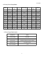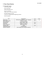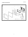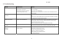
1
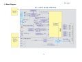
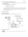
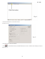
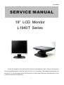
HP L1940T
SERVICE MANUAL
19” LCD Monitor
L1940T Series
THESE DOCUMENTS ARE FOR REPAIR SERVICE INFORMATION ONLY. EVERY REASONABLE
EFFORT HAS BEEN MADE TO ENSURE THE ACCURACY OF THIS MANUAL; WE CANNOT GUARANTEE THE
ACCURACY OF THIS INFORMATION AFTER THE DATE OF PUBLICATION AND DISCLAIMS RELIABILITY FOR
CHANGES, ERRORS OR OMISSIONS.
1
HP L1940T
Table of Contents
Table of Contents ------------------------------------------------------------------------------------------------------------------------ 02
Revision List ------------------------------------------------------------------------------------------------------------------------------ 03
1.Monitor Specification ----------------------------------------------------------------------------------------------------------------04
2.LCD Monitor Description ------------------------------------------------------------------------------------------------------------05
3.Operation Instructions ---------------------------------------------------------------------------------------------------------------05
3.1 General Instructions ---------------------------------------------------------------------------------------------------------------05
3.2 Control Button
---------------------------------------------------------------------------------------------------------------------06
3.3 Adjusting The Picture --------------------------------------------------------------------------------------------------------------06
4. Input/Output Specification -------------------------------------------------------------------------------------------------------- 09
4.1 Input Signal Connector -----------------------------------------------------------------------------------------------------------09
4.2 Factory Preset Display Modes --------------------------------------------------------------------------------------------------11
4.3 Power Supply Requirements ----------------------------------------------------------------------------------------------------11
5.Panel Specification ---------------------------------------------------------------------------------------------------------------------12
5.1 General Feature --------------------------------------------------------------------------------------------------------------------12
5.2 Optical Characteristics ------------------------------------------------------------------------------------------------------------13
6.Monitor Exploded View -----------------------------------------------------------------------------------------------------------------14
7.Repair Flow Chart
---------------------------------------------------------------------------------------------------------------------15
8. Trouble Shooting
-------------------------------------------------------------------------------------------------------------------18
9. Block Diagram
--------------------------------------------------------------------------------------------------------------------19
10. Schematic ------------------------------------------------------------------------------------------------------------------------------20
10.1Main Board
----------------------------------------------------------------------------------------------------------------------20
10.2 Inverter/Power Board
10.3 Key Board
-------------------------------------------------------------------------------------------------------25
------------------------------------------------------------------------------------------------------------------29
11. PCB Layout -----------------------------------------------------------------------------------------------------------------------------31
11.1 Main Board --------------------------------------------------------------------------------------------------------------------------31
11.2 Inverter/Power Board -------------------------------------------------------------------------------------------------------------32
11.3 Key Board ---------------------------------------------------------------------------------------------------------------------------33
12. Maintainability -------------------------------------------------------------------------------------------------------------------------34
13. White-Balance, Luminance Adjustment
------------------------------------------------------------------------------------ 35
14. Check List after replacing LCD Main board ---------------------------------------------------------------------------------37
14.1 Check white-balance -------------------------------------------------------------------------------------------------------------37
14.2 Steps for writing DDC ------------------------------------------------------------------------------------------------------------37
15. EDID Content --------------------------------------------------------------------------------------------------------------------------52
16. BOM List --------------------------------------------------------------------------------------------------------------------------53~64
2
HP L1940T
Revision List
Revision
Date
Revision History
TPV Model
A00
Feb.-24-06
Initial release
T981KMVDBHHPNP
3
HP L1940T
1.Monitor Specifications
LCD Panel
Input
Driving system
TFT Color LCD
Panel
M190E5-L0A
Active Area
376.32(H) x 301.056(V) (19.0")
Pixel pitch
0.294( H )x 0.294mm( V )
Viewing Angles(Min / TYP)
H:120/140; V:110/130
Response time (typ.)
< 8 ms
Brightness
200 nits
Contrast
450:1
Video
Analog /Digital
Sync. Type
H/V TTL
H-Frequency
30kHz – 83kHz
V-Frequency
56Hz – 76Hz
Display Colors
Over 16 million Colors
Pixel Clock
140MHz
Max. Resolution
1280 x 1024
Plug & Play
VESA DDC2BTM
Power Consumption
Power Source
Environmental
Considerations
ON Mode
≤70W
OFF Mode
<1W
Sleep Mode
<2W
100~240VAC,47~63Hz
Operating Temp: 5°C to 35°C
Storage Temp.: -20°C to 60°C
Operating Humidity: 20% to 80%
Unpackaged(W*H*D)
413mm*477mm*265mm
Packaged(W*H*D)
524mm*513mm*239mm
Packaged
10.22Kg Unit max
Unpackaged
8.4Kg Unit max
Operating
0 to 12,000 feet
Non-Operating
0 to 40,000 feet
Main Dimensions
Weight (N. W.)
Altitude
4
HP L1940T
2. LCD Monitor Description
The LCD Monitor will contain main board, power board, key board and which house the flat panel control logic,
brightness control logic and DDC.
The power board will provide AC to DC Inverter voltage to drive the backlight of panel and the main board chips
each voltage.
Monitor Block Diagram
Flat Panel and
CCFT Drive.
CCFL backlight
Main Board
Power Board
RS232 Connector
For white balance
adjustment in
factory mode
Keyboard
AC-IN
HOST Computer
110-240V
Video signal, DDC
3. Operation Instructions
3.1 General Instructions
Press the power button to turn the monitor on or off. The other control buttons are located at front of the panel.
By changing these settings, the picture can be adjusted to your personal performance.
-
The power cord should be connected .
-
Connect the video cable from the monitor to the computer VGA card.
-
Press the power button to turn on the monitor, the power indicator will light up to Green.
5
HP L1940T
3.2 Control Buttons
-
Power Indicator:
Green — Power On mode.
Orange — Power Saving mode.
Blank
—Power Off Mode.
Auto Adjust : Activates the auto adjustment feature for optimum image.
Menu : Opens the ON-Screen Display(OSD) menu.
Minus (–) : 1、If OSD is on, press to navigate backward through the OSD menu features and decrease
adjustment levels.
2、If OSD is off, press to enable the DVI signal input (available on select models).
plus (+) : 1、If OSD is on, press to navigate forward through the OSD menu features and increase adjustment
levels.
Power:
2、If OSD is off, press to enable the VGA signal input.
Turns the monitor on or off.
3.3 Adjust the Picture
Main Menu
Press the “Menu” button, the Main Menu should be come on the screen of the monitor
6
HP L1940T
Service Mode
Press and hold the “Menu” button, Power off -> on “Power”,then into the service mode, Press “menu” button to
bring to OSD menu for confirmation as below:
Factory Mode
1、 Turn off monitor.
2、 [ Push “Auto Adjust” and “+ (plus)”and hold them at the same time ]+ [ Press power “Power” button untill
comes out “windows screen” ] =>then release all button,then press “Menu”button,wait untill the OSD
menu with Characters “F” (below OSD menu) come on the Screen of the monitor as bellow:
3、 Pust “Menu” to exit OSD menu.
Factory Mode Indicator
7
HP L1940T
Menu icons
No.
Control
Icon
1
Brightness
2
Contrast
3
Auto Adjustment
4
Image Control
5
Color
6
Custom Color
7
Language
8
Management
9
OSD Control
10
Information
11
Factory Reset
12
Default Video Input
13
Horizontal Position
14
Vertical Position
15
Clock
16
Clock Phase
17
Power Saver
18
Mode Display
19
Power-On Status Display
20
Sleep Timer
21
Basic Menu
22
Advanced Menu
23
Power On Recall
24
Horizontal OSD Position
25
Vertical OSD Position
26
OSD Timeout
27
OSD Transparency
28
Exit
8
HP L1940T
4. Input/Output Specification
4.1 Input Signal Connector
Analog Connector Pinout
Pin
Mnemonic
Signal
Pin
Mnemonic
Signal
1
RV
Red Video
9
+5 V
+5 V (from PC)
2
GV
Green Video
10
SG
Sync Ground
3
BV
Blue Video
11
NC
None
4
NC
None
12
SDA
DDC Data
5
GND
GND / Cable Detect
13
HS
Horizontal Sync
6
RG
Red GND
14
VS
Vertical Sync
7
GG
Green GND
15
SCL
DDC Clock
8
BG
Blue GND
VGA connector layout
PIN 1
PIN 5
PIN 11
9
HP L1940T
DVI-D Digital Connector Pins
Pin.
Mnemonic
Signal
Pin.
Mnemonic
Signal
1
TX 2 -
TMDS Negative differential input, channel 2
13
TX 3 +
TMDS Data 3 +
2
TX 2 +
TMDS Positive differential input, channel 2
14
+5V
+5V Power
3
SHLD 2 / 4
Shield for TMDS channels 2 / 4
15
GND
GND / Cable Detect
4
TX 4 -
TMDS Data 4 -
16
HPD
Hot Plug Detect
5
TX 4 +
TMDS Data 4 +
17
TX 0 -
TMDS Data 0 -
6
DDC Clk
DDC Clock
18
TX 0 +
TMDS Data 0 +
7
DDC Data
DDC Data
19
SHLD 0 / 5
TMDS Data 0 / 5 Shield
8
AVS
Analog Vertical Sync
20
TX 5 -
TMDS Data 5 -
9
TX 1 -
TMDS Data 1 -
21
TX 5 +
TMDS Data 5 +
10
TX 1 +
TMDS Data 1 +
22
TX CLK SHLD TMDS Clock Shield
11
SHLD 1 / 3
TMDS Data 1 / 3 Shield
23
TX CLK +
TMDS Clock +
12
TX 3 -
TMDS Data 3 -
24
TX CLK -
TMDS Clock -
DVI-D Digital Connector Pins
10
HP L1940T
4.2 Factory Preset Display Modes
Pixel
Horz Freq
Horz
Vert
Pixel Clk
Format
(KHz)
Polarity
Polarity
(MHz)
1
640 x 480
31.469
-
59.940
-
25.175
VGA
2
640 x 480
37.861
-
72.809
-
31.500
VESA
3
640 x 480
37.500
-
75.000
-
31.500
VESA
4
720 x 400
31.469
-
70.087
+
28.322
VGA
5
800 x 600
37.879
+
60.317
+
40.000
VESA
6
800 x 600
48.077
+
72.188
+
50.000
VESA
7
800 x 600
46.875
+
75.000
+
49.500
VESA
8
832 x 624
49.726
±
74.551
±
57.284
MAC
9
1024 x 768
48.363
-
60.004
-
65.000
VESA
10
1024 x 768
56.476
-
70.069
-
75.000
VESA
11
1024 x 768
60.023
+
75.029
+
78.750
VESA
12
1152 x 870
68.68
-
75.06
-
100.000
Mac
13
1152 x 900
71.71
-
76.05
-
105.561
Sun
14
1280 x 1024
63.98
+
60.02
+
108.000
VESA
15
1280 x 1024
79.97
+
75.02
+
135.000
VESA
Preset
Vert Freq (Hz)
4.3 Power Supply Requirements
PARAMETER
RANGE
AC Input Voltage
90 to 265V
AC Input Frequency
47 to 63 Hz
Inrush Current
50A MAX AT 220VAC and 30A AT 120VAC
Leakage Current
5 mA MAX at 120VAC
Power consumption
≤70W
11
Source
HP L1940T
5. Panel Specification
5.1 General Feature
- Wide viewing angle.
- High contrast ratio
- Super fast response time
- High color saturation
- SXGA (1280 x 1024 pixels) resolution
- DE (Data Enable) only mode
- LVDS (Low Voltage Differential Signaling) interface
- RoHS Compliance
12
HP L1940T
5.2 Optical Characteristics
Test Conditions
Optical Specifications
13
HP L1940T
6. Monitor Exploded View
.
14
HP L1940T
7. Repair Flow Chart
15
HP L1940T
16
HP L1940T
17
HP L1940T
8. Troubleshooting
Problem
Possible Cause
Solution
Screen is blank.
Power cord is disconnected.
Connect the power cord.
Power switch is turned Off.
Turn on the power.
Video cable is improperly connected.
Connect the video cableproperly.
Screen blanking utility is active.
Depress any key on the keyboard or moveThe mouse to inactivate the screen
blanking Utility.
Image appears.blurred, indistinct,
Brightness and contrast are too low
or too dark.
Press the Minus button on the monitor front panel to auto-adjust the screen. If
that
Does not work, press the Menu button to open the Basic OSD Menu, and adjust
the brightness and contrast scales as needed.
Image is not Centered.
Position may need Adjustment
When OSD is inactive,press-(minus. button) to auto-adjust the screen image.
Press the Menu button to access the Advanced OSD menu. Select Image
Control/Horizontal Position or Vertical
Position to adjust the horizontal or vertical position of the image.
Check Video Cable is displayed
Monitor video cable is disconnected.
on screen.
Connect the 15-pin monitor video cable to the VGA connector on the computer.
Be sure that the computer power is off while: connecting the video Cable.
(Input Signal Out of Range) is
refresh rate are set higher than what your
Restart your computer and enter Windows
displayed
monitor supports.
Safe Mode by pressing the F6 Function
on screen.
key when the computer starts to boot up.
Change your settings to a supported
setting. Restart your computer so that the
new settings take effect.
18
HP L1940T
9. Block Diagram
19
HP L1940T
10. Schematic
10.1 Main Board
20
HP L1940T
21
HP L1940T
22
HP L1940T
23
HP L1940T
24
HP L1940T
10.2 Power Board (include inverter and power)
AC/DC Schematic
25
HP L1940T
Inverter Schematic
26
HP L1940T
AC/DC Function Block Schematic
27
HP L1940T
Inverter Function Block Schematic
28
HP L1940T
10.3 Key Board
29
HP L1940T
30
HP L1940T
11. PCB Layout
11.1 Main Board
31
HP L1940T
11.2 Inverter / Power Board
32
HP L1940T
11.3 Key Board
33
HP L1940T
12. Maintainability
Equipments and Tools Requirement
1、Multi-meter.
2、Oscilloscope.
3、Pattern Generator.
4、DDC Tool with an IBM Compatible Computer.
5、Alignment Tool.
6、LCD Color Analyzer.
7、Service Manual.
8、User Manual.
34
HP L1940T
13. White-Balance,Luminance Adjustment
Approximately 30 minutes should be allowed for warm up before proceeding
White-Balance adjustment.
1. How to do the Chroma-7120 MEM .Channel setting
A. Reference to chroma 7120 user guide
B. Use “ SC” key and “ NEXT” key to modify xyY value and use “ID” key to modify the
TEXT description Following is the procedure to do white-balance adjust
2. Setting the color temp. You want
A. 9300 color:
9300 color temp. parameter is x = 283 ±20, y = 297 ±20, Y = 180 cd/m2 ,
B. 6500K color:
6500K color temp. parameter is x = 313±20, y = 329 ±20, Y= 180 cd/m2)
C. sRGB color:
sRGB color temp. parameter is x = 313±20, y = 329 ±20, Y= 150 cd/m2)
3. Into factory mode of HP L1940T
[ Push “Auto Adjust” and “+ (plus)”and hold them at the same time ]+ [ Press power “Power” button untill
comes out “windows screen” ] =>then release all button,then press “Menu”button,wait untill the OSD menu
with Characters “F” come on the Screen of the monitor.
4. Bias adjustment:
Set the Contrast
to 80
Adjust the Brightness
to 90.
5. Gain adjustment :
Move cursor to “-F-” and press MENU key
A. Adjus 9300k color-temperature
1. Switch the Chroma-7120 to 9300k channel.
2. The chroma 7120 will show x = 283±20, y = 297 ±20, Y= 180 cd/m2
3. Switch the chroma-720 to RGB MODE (with press “MODE” button to change )
4. Adjust the RED of color 9300K on factory window until chroma 7120 indicator reached
the value
R=100
5. Adjust the GREEN of color 9300K on factory window until chroma 7120 indicator reached
the value G=100
6. Adjust the BLUE of color 9300K on factory window until chroma 7120 indicator reached
the value B=100
7. Repeat above procedure ( item 4,5,6) until chroma 7120 RGB value meet the
tolerance =100±2
B. Adjust 6500K color-temperature
1. Switch the chroma-7120 to 6500K channel.
35
HP L1940T
2. The chroma 7120 will show x = 313 ±20, y = 329 ±20, Y = 180 cd/m2
3. Switch the chroma 7120 l to RGB MODE ( with press “MODE” button to change )
4. Adjust the RED of color 6500K on factory window until chroma 7120 indicator reached
the value R=100
5. Adjust the GREEN of color 6500K on factory window until chroma 7120 indicator reached
the value G=100
6. Adjust the BLUE of color 6500K on factory window until chroma 7120 indicator reached
the value B=100
7. Repeat above procedure ( item 4,5,6) until chroma 7120 RGB value meet the
tolerance =100±2
C. Adjust sRGB color-temperature
1. Switch the chroma-7120 to sRGB channel.
2. The chroma 7120 will show x = 313 ±20, y = 329 ±20, Y = 150 cd/m2
3. Switch the chroma 7120 l to RGB MODE (with press “MODE” button to change)
4. Adjust the RED of color sRGB on factory window until chroma 7120 indicator reached
the value R=100
5. Adjust the GREEN of color sRGB on factory window until chroma 7120 indicator reached
the value G=100
6. Adjust the BLUE of color sRGB on factory window until chroma 7120 indicator reached
the value B=100
7. Repeat above procedure (item 4,5,6) until chroma 7120 RGB value meet the
tolerance =100±2
D. Press reset key and Turn the Power-button “off to on” to quit from factory mode.
36
HP L1940T
14. Check List after replacing LCD Main board
Check if white-balance is within the specs after replacing Main board and panel, then re-writing DDC is necessary.
14.1 Check white-balance
The white-balance value for each common color temperature:
9300 º K: x=283± 20 ; y = 297± 20;
6500K: x = 313± 20 ; y = 329 ± 20;
sRGB: x = 313± 20 ; y = 329 ± 20;
The color temperature value above must be up to the situation of x<y. The value of Y should be confirmed
according to different customers. 15 ”LCD is commonly 180±20cd/cm2(Center)and 17” LCD is required to be
larger than 200cd/cm2 (Center). The exact brightness values are confirmed by the checking-regulations of
different customers and different models.
14.2 Steps for writing DDC:
Re-programming Analog DDC IC
Step 1: After initialize alignment box, connecting all cables and box as shown in Fig. 10.
Step 2: Read DDC data from monitor
1. Click
icon as shown in Fig. 11 from the tool bar to bring up the Channels "Configuration Setup" windows as
shown in Fig. 11.
37
HP L1940T
2. Select the DDC2Bi as the communication channel.
As shown in Fig. 12.
3. Click OK button to confirm your selection.
4. Click
icon (Read EDID function) to read DDC EDID data from monitor. The EDID codes will display on screen as
shown in Fig. 13.
38
HP L1940T
Step 3: Modify DDC data (verify EDID version, week, year)
Click (new function) icon from the tool bar, bring up Step 1 of 9 as shown in Fig. 14 .
EDID4.6 DDC application provides the function selection and text change (select & fill out)from Step 1 to Step 9.
Step 4: Modify DDC data (Monitor Serial No.)
1. Click Next , bring up Fig. 15.
39
HP L1940T
2. Click Next , bring up Fig.16.
3. Click Next , bring up Fig.17.
40
HP L1940T
4. Click Next , bring up Fig.18.
5. Click Next , bring up Fig.19.
41
HP L1940T
6. Click Next , bring up Fig. 20.
In this step, please confirm the Descriptor Data Type is Monitor Range Limits, and all the items are same as below.
7. Click Next , bring up Fig. 21.
42
HP L1940T
T
8. Click Next , bring up Fig. 22.
- Click Finish to exit the Step window.
- Serial number can be filled up at this moment (for example,TWP318Q001).
NOTE: You must modify the Serial NO. In step 9, otherwise the Serial NO. In OSD Couldn't be modified correctly.
Step 5: Write DDC data
1. Configuration should be as Fig. 23. And press OK.
43
HP L1940T
2. Access Factory Mode
1). Turn off monitor.
2). [Push "Auto Adjust " and" +(plus)"and hold them at the same time ] + [Press power "Power " button untill comes out
"Windows screen"] => then release all button, then press "Menu" button, wait until the OSD menu with Characters "F"
(below OSD menu) come on the Screen of the monitor (see Fig. 24).
3) Push Menu to exit OSD menu.
4). Click
(Write EDID) icon from the tool bar to write DDC data. Then the screen will be black for 5-10 seconds, when
the screen recovers ,DDC data will be finished Writing.
Step 6: Save DDC data
44
HP L1940T
Sometimes, you may need to save DDC data as a text file for using in other IC chip. To save DDC data, follow the steps
below:
1. Click
(Save) icon (or click "file"-> "save as") from the tool bar and give a file name as shown in Fig. 25. The file
type is EDID46 file (*.ddc) which can be open in WordPad. By using WordPad, the texts of DDC data & table (128 bytes,
hex code) can be modified. If DDC TEXTS & HEX Table ar completely correct, it can be saved as .ddc flie to re-load it into
DDC IC for DDC Data application.
2. Click Save.
Step 7: Exit DDC program
Pull down the File menu and select Exit as shown in Fig. 26.
Step 8: Turn off the monitor, exit the factory mode.
Re-programming Digital DDC IC
Step 1: After initialize alignment box, connecting all cables and box as shown in Fig. 27.
45
HP L1940T
Step 2: Read DDC data from monitor
1. Click icon as shown in Fig. 11 from the tool bar to bring up the Channels "Configuration Setup" windows as shown in Fig.
28.
2. Select the DDC2Bi as the communication channel. As shown in Fig. 29.
46
HP L1940T
3. Click OK button to confirm your selection.
4. Click
icon (Read EDID function) to read DDC EDID data from monitor. The EDID codes will display on screen as
shown in Fig. 30.
Step 3: Modify DDC data (verify EDID version, week, year)
Click
(new function) icon from the tool bar, bring up Step 1 of 9 as shown in Fig. 31 .
EDID46 DDC application provides the function selection and text change (select & fill out) from Step 1 to Step 9.
Step 4: Modify DDC data (Monitor Serial No.)
1. Click Next , bring up Fig. 32.
47
HP L1940T
2. Click Next , bring up Fig. 33. Fig. 33 Fig. 34
3. Click Next , bring up Fig. 34.
4. Click Next , bring up Fig. 35.
5. Click Next , bring up Fig. 36.
6. Click Next , bring up Fig. 37.
In this step, please confirm the Descriptor Data Type is Monitor Range Limits, and all the items are same as below.
7. Click Next , bring up Fig. 38.
48
HP L1940T
8. Click Next , bring up Fig. 39.
- Click Finish to exit the Step window.
- Serial number can be filled up at this moment (for example, TWP318Q001).
NOTE: You must modify the Serial NO. In step 9, otherwise the Serial NO. In OSD Couldn't be modified correctly.
Step 5: Write DDC data
1. Configuration should be as Fig. 40. And press OK.
2. Access Factory Mode
1). Turn off monitor.
2). [Push "Auto Adjust " and "+(plus) and hold them at the same time ] + [Press power "Power " button untill comes out
"Windows screen"] => then release all button, then press "Menu" button, wait until the OSD menu with Character "F"
(below OSD menu) come on the Screen of the monitor (see Fig. 41).
49
HP L1940T
3) Push Menu to exit OSD menu.
3. Click
(Write EDID) icon from the tool bar to write DDC data.Then the screen will be black for 5-10 seconds,
when the screen recovers ,DDC data will be finished Writing.
4. Confirm Serial Number in User Mode
1) Press the "Power " button to turn off the monitor. Press the button again to turn on the monitor.
2) Press the" Menu " button to bring up the OSD main menu.
3) Press the " Minus "button to " INFORMATION", press the" Menu " button to confirm your selection.
4) Confirm the Serial Number "TWP318Q001" is updated as shown in Fig. 42.
Step 6: Save DDC data
Sometimes, you may need to save DDC data as a text file for using in other IC chip. To save DDC data, follow the steps
below:
50
HP L1940T
1. Click (Save) icon (or click "file"-> "save as") from the tool bar and give a file name as shown in Fig. 46.
The file type is EDID46 file (*.ddc) which can be open in WordPad. By using WordPad, the texts of DDC data & table (128
bytes, hex code) can be modified. If DDC TEXTS & HEX Table ar completely correct, it can be saved as *.ddc flie to
re-load it into DDC IC for DDC Data application.
2. Click Save.
Step 7: Exit DDC program
Pull down the File menu and select Exit as shown in Fig. 44.
Step 8: Turn off the monitor, exit the factory mode.
51
HP L1940T
15. EDID Content
Analog
00
01
02
03
04
05
06
07
08
09
10
11
12
13
14
15
0:
00
FF
FF
FF
FF
FF
FF
00
22
F0
2E
26
01
01
01
01
16 :
36
10
01
03
68
26
1E
78
EE
EE
95
A3
54
4C
99
26
32 :
0F
50
54
AD
EF
80
81
80
01
01
01
01
01
01
01
01
48 :
01
01
01
01
01
01
30
2A
00
98
51
00
2A
40
30
70
64 :
13
00
52
0E
11
00
00
1E
00
00
00
FF
00
32
31
33
80 :
36
35
34
39
38
37
35
0A
20
20
00
00
00
FD
00
38
96 :
4C
1E
53
0E
00
0A
20
20
20
20
20
20
00
00
00
FC
112:
00
48
50
20
4C
31
39
34
30
54
0A
20
20
20
00
3D
00
01
02
03
04
05
06
07
08
09
10
11
12
13
14
15
0:
00
FF
FF
FF
FF
FF
FF
00
22
F0
2F
26
01
01
01
01
16 :
02
0E
01
03
80
26
1E
78
EE
EE
95
A3
54
4C
99
26
32 :
0F
50
54
AD
EF
80
81
80
01
01
01
01
01
01
01
01
48 :
01
01
01
01
01
01
30
2A
00
98
51
00
2A
40
30
70
64 :
13
00
52
0E
11
00
00
1E
00
00
00
FF
00
43
4E
43
80 :
34
30
32
31
32
33
34
0A
20
20
00
00
00
FD
00
38
96 :
4C
1E
53
0E
00
0A
20
20
20
20
20
20
00
00
00
FC
112:
00
48
50
20
4C
31
39
34
30
54
0A
20
20
20
00
38
Digital
52
HP L1940T
16. BOM List
T981KMVDBHHPNP
Location
Part No. for TPV
007G
7 L151
Description
Quantity
Unit
COMPOUND PALLET
0.025
PCS
92
015G6344 1
AC BRACKET
1.000
PCS
34
023G3178690 7A
HP LOGO 7121-8115
1.000
PCS
034G6402 EY B
REAR COVER
1.000
PCS
037G6057 2
HINGE
1.000
PCS
040G 152509
RECYCLE LABEL
1.000
PCS
040G 152512
RECYCLE LABEL
1.000
PCS
040G 58169016A
TCO'03 LABEL
1.000
PCS
040G 582690 1A
CARTON LABLE
1.000
PCS
040G 582690 2A
PALLET LABLE
0.050
PCS
040G19NP690 1B
RATING LABEL
1.000
PCS
041G160069041A
L1940T FOR EUR
1.000
PCS
041G7800690A12
RTF CARD
1.000
PCS
041G7800690A16
QSG FOR EUR
1.000
PCS
041G7800690B01
SCREEN RESOLUTION
1.000
PCS
451
044G3957 1
CUSHION-R
1.000
PCS
452
044G3957 2
CUSHION-L
1.000
PCS
450
044G3957690 1A
CARTON
1.000
PCS
044G6002757 1A
PAPER PLATE
0.050
PCS
044G9003 12
CORNER PAPER
0.050
PCS
044G9003210
CORNER PAPER
0.100
PCS
148
045G 88609 28
BASE P.E BAG
1.000
PCS
456
045G 88609 29
P.E.BAG(EPE)
1.000
PCS
457
050G 505 2
WRAPPING BAND
1.000
PCS
052G
1185
MIDDLE TAPE FOR CARTON
70.000
CM
052G
1186
SMALL TAPE
8.000
CM
94
052G6022 1500
SMALL TAPE
1.000
CM
341
052G6025 11975
INSULATION PLATE
1.000
PCS
302
052G6025 11976
INSULATION PLATE
1.000
PCS
E80
080G L19502 FC
PSU OPENFR IPS 35W(T50P057.02)
1.000
PCS
340
085G6157 1
MAIN SHIELD
1.000
PCS
1159
089G 175507
USB CABLE
1.000
PCS
E095B
089G 718RAADP1
CORD SUB-D 15/1M8/15 D-SUB BK
1.000
PCS
E095B
089G 718WAADP1
CORD SUB-D 15/1M8/SUB-D 15BK
1.000
PCS
089G179J 30713
FFC 30PIN P1.0
1.000
PCS
089G404A19N LS
POWER CORD
1.000
PCS
E089A
53
HP L1940T
8161
095G8P14 7505
CBLE-267 7/330/7-267 AWG28
1.000
PCS
8161
095G8P14 7505
CBLE-267 7/330/7-267 AWG28
1.000
PCS
0M1G 130 4225
SCREW
4.000
PCS
0M1G1340 10 47
SCREW M4X10 BLK
4.000
PCS
0M1G1430 5128
SCREW (FOR SHIELD)
1.000
PCS
97
0M1G1430 5128
SCREW (FOR SHIELD)
4.000
PCS
95
0M1G1640 8120
SCREW PHM4-0.7X8
1.000
PCS
0M1G1730 6120
SCREW
4.000
PCS
99
0Q1G 130 8128
SCREW
2.000
PCS
96
0Q1G1130 6128
TAPPING SCREW WITH WASHER
3.000
PCS
705G980KF34007
BEZEL ASS'Y
1.000
PCS
705G980KM34004
MAIN FRAME ASS'Y
1.000
PCS
750GLM90E5A11Z
PANEL LCD 19" E5-L05 C1 D CMO
1.000
PCS
CBPC980KMVHPP
CONVERSION BOARD
1.000
PCS
KEPC780HP1P
KEY BOARD
1.000
PCS
PWPC1942LGH5P
POWER BOARD
1.000
PCS
0Q1G 330 8120
SCREW 3X8mm
2.000
PCS
705G980KF34007
BEZEL ASS'Y
0.000
033G6429 PM B
CONTROL BUTTON
1.000
PCS
033G6430 1 C
LENS-POWER
1.000
PCS
034G6401AFH B
BEZEL
1.000
PCS
705G980KM34004
MAIN FRAME ASS'Y
0.000
015G6343 1
MAIN FRAME-LPL
1.000
PCS
052G6025 11981
MYLAR
1.000
PCS
CBPC980KMVHPP
CONVERSION BOARD
0.000
1503
033G3802 7
WAFER EH 7
1.000
PCS
1502
033G3802 14
14P/2.0MM
1.000
PCS
040G 457624 1B
LABEL-CPU
1.000
PCS
040G 45762412B
CBPC LABEL
1.000
PCS
7302
056G11332PH
IC M24C16-WBN6 (ST00)L
1.000
PCS
7608
056G1133521
IC AT93C46-10PU-2.7 ATMEL
1.000
PCS
2622
067G 305101 4P
ELCAP KM 25V S 100U PM20 B
1.000
PCS
2624
067G 305101 4P
ELCAP KM 25V S 100U PM20 B
1.000
PCS
2622
067G 305101 4X
ELCAP RGA 25V S 100U PM20 B
1.000
PCS
2624
067G 305101 4X
ELCAP RGA 25V S 100U PM20 B
1.000
PCS
2515
067G 305470 4P
1.000
PCS
2515
067G 305470 4X
1.000
PCS
2519
067G215L471 4R
LOW E.S.R 470UF +/-20% 25V
1.000
PCS
5504
073G 253518 LS
COI CHOKE 35UH 82M OHM DR10X8
1.000
PCS
5411
073G 25833010T
IND FXD TSL0808 S 33U PM10 B
1.000
PCS
5504
073L 253518 HJ
COI CHOKE 35UH 82M OHM DR10X8
1.000
PCS
100
E750L
E80
ELCAP
KM
25V S
ELCAP RGA 25V S
54
47U PM20
47U PM20
B
B
HP L1940T
1603
088G 350 1 TN
USB CONN
1.000
PCS
1602
088G 351 2B CL
USB CONN
1.000
PCS
1602
088G 351 2B TN
USB CONN
1.000
PCS
1203
088G 35315F H
D-SUB 15PIN
1.000
PCS
1203
088G 35315F HJ
SOC SUBD H 15P F
1.000
PCS
1203
088G 35315F HJ
SOC SUBD H 15P F
1.000
PCS
1201
088G 35424F H
DV1 CONNECTOR 24PIN
1.000
PCS
1201
088G 35424F SM
1.000
PCS
1201
088G 35424FHCJ
DVI 24PIN
1.000
PCS
6501
093G 521ZJ26T
SB240
1.000
PCS
6501
093G 523DI26T
DIO REC SB240-E3 A(VISH)B
1.000
PCS
AIC980KMVHPP
MAIN BOARD
1.000
PCS
KEPC780HP1P
KEY BOARD
0.000
033G3802 7
WAFER EH 7
1.000
PCS
AIK780HP1SMTP
KEY BOARD FOR SMT
1.000
PCS
AIC980KMVHPP
MAIN BOARD
0.000
1412
033G801930L FP
CON H 30P F 1.00 SM FFC 0.3R
1.000
PCS
7403
056G 1331PH
IC SM LD1117AS18(ST00)R
1.000
PCS
7505
056G 158805
IC L5972D013TR S08
1.000
PCS
7601
056G 545500
USB HUB CONTROLLER
1.000
PCS
7401
056G 562 70
GM5321 QFP-208
1.000
PCS
7403
056G 563 27
AIC1117-18PY
1.000
PCS
7202
056G1133 20
AT24C02N-10SU-2.7
1.000
PCS
7203
056G1133 20
AT24C02N-10SU-2.7
1.000
PCS
7202
056G1133 34
M24C02-WMN6TP
1.000
PCS
7203
056G1133 34
M24C02-WMN6TP
1.000
PCS
7301
056G1133519
IC AT49BV002ANT-70JU ATMEL
1.000
PCS
7210
056G4LCX 14 PH
IC 74LVC14APW PHILIPS
1.000
PCS
7210
056G4LCX 14 ST
IC SM 74LCX14T
1.000
PCS
7501
057G 420519 T
TRA SIG SM BC857CG (ONSE) R
1.000
PCS
7502
057G 420519 T
TRA SIG SM BC857CG (ONSE) R
1.000
PCS
7503
057G 760 8 T
KRC102M-ATP
1.000
PCS
7503
057G 7601PH
TRA SIG SM MUN2211J(ONSE)R
1.000
PCS
7504
057G 7631PH
FET POW SM SI5441DC(VISH)R
1.000
PCS
3620
061G 56075 WT
PTC KMC 5S075R001-0.75MA
1.000
PCS
3622
061G 56075 WT
PTC KMC 5S075R001-0.75MA
1.000
PCS
3651
061L0603000
RST SM 0603 JUMP MAX 0R05 R
1.000
PCS
3652
061L0603000
RST SM 0603 JUMP MAX 0R05 R
1.000
PCS
3653
061L0603000
RST SM 0603 JUMP MAX 0R05 R
1.000
PCS
3650
061L0603000
RST SM 0603 JUMP MAX 0R05 R
1.000
PCS
3635
061L0603000
RST SM 0603 JUMP MAX 0R05 R
1.000
PCS
1931
SOC DVI H 24P F
55
1.91DVI-D Y
HP L1940T
3634
061L0603000
RST SM 0603 JUMP MAX 0R05 R
1.000
PCS
3614
061L0603000
RST SM 0603 JUMP MAX 0R05 R
1.000
PCS
3606
061L0603000
RST SM 0603 JUMP MAX 0R05 R
1.000
PCS
3605
061L0603000
RST SM 0603 JUMP MAX 0R05 R
1.000
PCS
3528
061L0603000
RST SM 0603 JUMP MAX 0R05 R
1.000
PCS
3527
061L0603000
RST SM 0603 JUMP MAX 0R05 R
1.000
PCS
3514
061L0603000
RST SM 0603 JUMP MAX 0R05 R
1.000
PCS
3236
061L0603000
RST SM 0603 JUMP MAX 0R05 R
1.000
PCS
3234
061L0603000
RST SM 0603 JUMP MAX 0R05 R
1.000
PCS
3232
061L0603000
RST SM 0603 JUMP MAX 0R05 R
1.000
PCS
3243
061L0603100
CHIP 10 OHM 1/10W
1.000
PCS
3241
061L0603100
CHIP 10 OHM 1/10W
1.000
PCS
3223
061L0603101
CHIPR 100 OHM +-5% 1/16W
1.000
PCS
3224
061L0603101
CHIPR 100 OHM +-5% 1/16W
1.000
PCS
3225
061L0603101
CHIPR 100 OHM +-5% 1/16W
1.000
PCS
3226
061L0603101
CHIPR 100 OHM +-5% 1/16W
1.000
PCS
3308
061L0603101
CHIPR 100 OHM +-5% 1/16W
1.000
PCS
3309
061L0603101
CHIPR 100 OHM +-5% 1/16W
1.000
PCS
3340
061L0603101
CHIPR 100 OHM +-5% 1/16W
1.000
PCS
3401
061L0603101
CHIPR 100 OHM +-5% 1/16W
1.000
PCS
3402
061L0603101
CHIPR 100 OHM +-5% 1/16W
1.000
PCS
3505
061L0603101
CHIPR 100 OHM +-5% 1/16W
1.000
PCS
3506
061L0603101
CHIPR 100 OHM +-5% 1/16W
1.000
PCS
3507
061L0603101
CHIPR 100 OHM +-5% 1/16W
1.000
PCS
3206
061L0603101
CHIPR 100 OHM +-5% 1/16W
1.000
PCS
3207
061L0603101
CHIPR 100 OHM +-5% 1/16W
1.000
PCS
3210
061L0603101
CHIPR 100 OHM +-5% 1/16W
1.000
PCS
3211
061L0603101
CHIPR 100 OHM +-5% 1/16W
1.000
PCS
3212
061L0603101
CHIPR 100 OHM +-5% 1/16W
1.000
PCS
3216
061L0603101
CHIPR 100 OHM +-5% 1/16W
1.000
PCS
3217
061L0603101
CHIPR 100 OHM +-5% 1/16W
1.000
PCS
3218
061L0603101
CHIPR 100 OHM +-5% 1/16W
1.000
PCS
3219
061L0603101
CHIPR 100 OHM +-5% 1/16W
1.000
PCS
3306
061L0603103
CHIPR 10K OHM +-5% 1/16W
1.000
PCS
3307
061L0603103
CHIPR 10K OHM +-5% 1/16W
1.000
PCS
3310
061L0603103
CHIPR 10K OHM +-5% 1/16W
1.000
PCS
3333
061L0603103
CHIPR 10K OHM +-5% 1/16W
1.000
PCS
3338
061L0603103
CHIPR 10K OHM +-5% 1/16W
1.000
PCS
3339
061L0603103
CHIPR 10K OHM +-5% 1/16W
1.000
PCS
3503
061L0603103
CHIPR 10K OHM +-5% 1/16W
1.000
PCS
3511
061L0603103
CHIPR 10K OHM +-5% 1/16W
1.000
PCS
56
HP L1940T
3512
061L0603103
CHIPR 10K OHM +-5% 1/16W
1.000
PCS
3522
061L0603103
CHIPR 10K OHM +-5% 1/16W
1.000
PCS
3523
061L0603103
CHIPR 10K OHM +-5% 1/16W
1.000
PCS
3617
061L0603103
CHIPR 10K OHM +-5% 1/16W
1.000
PCS
3608
061L0603103
CHIPR 10K OHM +-5% 1/16W
1.000
PCS
3524
061L0603103
CHIPR 10K OHM +-5% 1/16W
1.000
PCS
3202
061L0603103
CHIPR 10K OHM +-5% 1/16W
1.000
PCS
3203
061L0603103
CHIPR 10K OHM +-5% 1/16W
1.000
PCS
3204
061L0603103
CHIPR 10K OHM +-5% 1/16W
1.000
PCS
3221
061L0603103
CHIPR 10K OHM +-5% 1/16W
1.000
PCS
3222
061L0603103
CHIPR 10K OHM +-5% 1/16W
1.000
PCS
3230
061L0603103
CHIPR 10K OHM +-5% 1/16W
1.000
PCS
3242
061L0603103
CHIPR 10K OHM +-5% 1/16W
1.000
PCS
3246
061L0603103
CHIPR 10K OHM +-5% 1/16W
1.000
PCS
3247
061L0603103
CHIPR 10K OHM +-5% 1/16W
1.000
PCS
3301
061L0603103
CHIPR 10K OHM +-5% 1/16W
1.000
PCS
3302
061L0603103
CHIPR 10K OHM +-5% 1/16W
1.000
PCS
3611
061L0603104
RST SM 0603 RC0603 100K PM5 R
1.000
PCS
3516
061L0603104
RST SM 0603 RC0603 100K PM5 R
1.000
PCS
3515
061L0603104
RST SM 0603 RC0603 100K PM5 R
1.000
PCS
3209
061L0603104
RST SM 0603 RC0603 100K PM5 R
1.000
PCS
3229
061L0603104
RST SM 0603 RC0603 100K PM5 R
1.000
PCS
3615
061L0603105
RST SM 0603 RC0603 1M PM5 R
1.000
PCS
3621
061L0603105
RST SM 0603 RC0603 1M PM5 R
1.000
PCS
3623
061L0603105
RST SM 0603 RC0603 1M PM5 R
1.000
PCS
3406
061L0603121
CHIPR 120 OHM 1/10W
1.000
PCS
3405
061L0603121
CHIPR 120 OHM 1/10W
1.000
PCS
3404
061L0603121
CHIPR 120 OHM 1/10W
1.000
PCS
3610
061L0603152
CHIPR 1.5KOHM+-5% 1/16W
1.000
PCS
3657
061L0603153
CHIPR 15KOHM+-5% 1/10W
1.000
PCS
3656
061L0603153
CHIPR 15KOHM+-5% 1/10W
1.000
PCS
3655
061L0603153
CHIPR 15KOHM+-5% 1/10W
1.000
PCS
3654
061L0603153
CHIPR 15KOHM+-5% 1/10W
1.000
PCS
3509
061L0603221
CHIPR 220 OHM+-5% 1/16W
1.000
PCS
3510
061L0603221
CHIPR 220 OHM+-5% 1/16W
1.000
PCS
3227
061L0603222
CHIPR 2.2K OHM+-5% 1/16W
1.000
PCS
3228
061L0603222
CHIPR 2.2K OHM+-5% 1/16W
1.000
PCS
3408
061L0603249 0F
CHIP 249OHM 1/16W 1%
1.000
PCS
3645
061L0603330 9F
rst sm 0603 rc22h
33r pm1 r
1.000
PCS
3646
061L0603330 9F
rst sm 0603 rc22h
33r pm1 r
1.000
PCS
3649
061L0603330 9F
rst sm 0603 rc22h
33r pm1 r
1.000
PCS
57
HP L1940T
3642
061L0603330 9F
rst sm 0603 rc22h
33r pm1 r
1.000
PCS
3633
061L0603330 9F
rst sm 0603 rc22h
33r pm1 r
1.000
PCS
3630
061L0603330 9F
rst sm 0603 rc22h
33r pm1 r
1.000
PCS
3502
061L0603470
CHIPR 47 OHM +-5% 1/16W
1.000
PCS
3501
061L0603470
CHIPR 47 OHM +-5% 1/16W
1.000
PCS
3413
061L0603470
CHIPR 47 OHM +-5% 1/16W
1.000
PCS
3409
061L0603470
CHIPR 47 OHM +-5% 1/16W
1.000
PCS
3245
061L0603470
CHIPR 47 OHM +-5% 1/16W
1.000
PCS
3244
061L0603470
CHIPR 47 OHM +-5% 1/16W
1.000
PCS
3616
061L0603473
RST SM 0603 RC0603 47K PM5 R
1.000
PCS
3613
061L0603680 0F
1.000
PCS
3233
061L0603750 9F
75OHM 1% 1/10W
1.000
PCS
3235
061L0603750 9F
75OHM 1% 1/10W
1.000
PCS
3237
061L0603750 9F
75OHM 1% 1/10W
1.000
PCS
3520
061L0805180 1F
1.000
PCS
3519
061L0805472
1.000
PCS
3521
061L0805560 1F
1.000
PCS
3618
061L1206000
CHIPR 0 OHM +-5% 1/8W
1.000
PCS
3607
061L1206000
CHIPR 0 OHM +-5% 1/8W
1.000
PCS
3517
061L1206000
CHIPR 0 OHM +-5% 1/8W
1.000
PCS
2455
065G0603103 32
0.01UF +-10% 50V X7R
1.000
PCS
2454
065G0603103 32
0.01UF +-10% 50V X7R
1.000
PCS
2453
065G0603103 32
0.01UF +-10% 50V X7R
1.000
PCS
2452
065G0603103 32
0.01UF +-10% 50V X7R
1.000
PCS
2229
065G0603103 32
0.01UF +-10% 50V X7R
1.000
PCS
2227
065G0603103 32
0.01UF +-10% 50V X7R
1.000
PCS
2225
065G0603103 32
0.01UF +-10% 50V X7R
1.000
PCS
2511
065G0603104 12
CER2 0603 X7R 16V 100N PM10 R
1.000
PCS
2513
065G0603104 12
CER2 0603 X7R 16V 100N PM10 R
1.000
PCS
2521
065G0603104 12
CER2 0603 X7R 16V 100N PM10 R
1.000
PCS
2510
065G0603104 12
CER2 0603 X7R 16V 100N PM10 R
1.000
PCS
2508
065G0603104 12
CER2 0603 X7R 16V 100N PM10 R
1.000
PCS
2507
065G0603104 12
CER2 0603 X7R 16V 100N PM10 R
1.000
PCS
2505
065G0603104 12
CER2 0603 X7R 16V 100N PM10 R
1.000
PCS
2504
065G0603104 12
CER2 0603 X7R 16V 100N PM10 R
1.000
PCS
2461
065G0603104 12
CER2 0603 X7R 16V 100N PM10 R
1.000
PCS
2446
065G0603104 12
CER2 0603 X7R 16V 100N PM10 R
1.000
PCS
2445
065G0603104 12
CER2 0603 X7R 16V 100N PM10 R
1.000
PCS
2444
065G0603104 12
CER2 0603 X7R 16V 100N PM10 R
1.000
PCS
2443
065G0603104 12
CER2 0603 X7R 16V 100N PM10 R
1.000
PCS
2442
065G0603104 12
CER2 0603 X7R 16V 100N PM10 R
1.000
PCS
RST SM 0603 RC22H
RST SM 005 RC12H
680R PM1 R
1K8 PM1 R
CHIRP 4.7K OHM +-5% 1/10W
RST SM 0805 RC12H
58
5K6 PM1
R
HP L1940T
2441
065G0603104 12
CER2 0603 X7R 16V 100N PM10 R
1.000
PCS
2440
065G0603104 12
CER2 0603 X7R 16V 100N PM10 R
1.000
PCS
2438
065G0603104 12
CER2 0603 X7R 16V 100N PM10 R
1.000
PCS
2436
065G0603104 12
CER2 0603 X7R 16V 100N PM10 R
1.000
PCS
2434
065G0603104 12
CER2 0603 X7R 16V 100N PM10 R
1.000
PCS
2523
065G0603104 12
CER2 0603 X7R 16V 100N PM10 R
1.000
PCS
2623
065G0603104 12
CER2 0603 X7R 16V 100N PM10 R
1.000
PCS
2625
065G0603104 12
CER2 0603 X7R 16V 100N PM10 R
1.000
PCS
2630
065G0603104 12
CER2 0603 X7R 16V 100N PM10 R
1.000
PCS
2619
065G0603104 12
CER2 0603 X7R 16V 100N PM10 R
1.000
PCS
2618
065G0603104 12
CER2 0603 X7R 16V 100N PM10 R
1.000
PCS
2615
065G0603104 12
CER2 0603 X7R 16V 100N PM10 R
1.000
PCS
2612
065G0603104 12
CER2 0603 X7R 16V 100N PM10 R
1.000
PCS
2611
065G0603104 12
CER2 0603 X7R 16V 100N PM10 R
1.000
PCS
2610
065G0603104 12
CER2 0603 X7R 16V 100N PM10 R
1.000
PCS
2609
065G0603104 12
CER2 0603 X7R 16V 100N PM10 R
1.000
PCS
2608
065G0603104 12
CER2 0603 X7R 16V 100N PM10 R
1.000
PCS
2607
065G0603104 12
CER2 0603 X7R 16V 100N PM10 R
1.000
PCS
2606
065G0603104 12
CER2 0603 X7R 16V 100N PM10 R
1.000
PCS
2605
065G0603104 12
CER2 0603 X7R 16V 100N PM10 R
1.000
PCS
2604
065G0603104 12
CER2 0603 X7R 16V 100N PM10 R
1.000
PCS
2603
065G0603104 12
CER2 0603 X7R 16V 100N PM10 R
1.000
PCS
2531
065G0603104 12
CER2 0603 X7R 16V 100N PM10 R
1.000
PCS
2529
065G0603104 12
CER2 0603 X7R 16V 100N PM10 R
1.000
PCS
2525
065G0603104 12
CER2 0603 X7R 16V 100N PM10 R
1.000
PCS
2407
065G0603104 12
CER2 0603 X7R 16V 100N PM10 R
1.000
PCS
2406
065G0603104 12
CER2 0603 X7R 16V 100N PM10 R
1.000
PCS
2405
065G0603104 12
CER2 0603 X7R 16V 100N PM10 R
1.000
PCS
2404
065G0603104 12
CER2 0603 X7R 16V 100N PM10 R
1.000
PCS
2403
065G0603104 12
CER2 0603 X7R 16V 100N PM10 R
1.000
PCS
2302
065G0603104 12
CER2 0603 X7R 16V 100N PM10 R
1.000
PCS
2301
065G0603104 12
CER2 0603 X7R 16V 100N PM10 R
1.000
PCS
2234
065G0603104 12
CER2 0603 X7R 16V 100N PM10 R
1.000
PCS
2233
065G0603104 12
CER2 0603 X7R 16V 100N PM10 R
1.000
PCS
2231
065G0603104 12
CER2 0603 X7R 16V 100N PM10 R
1.000
PCS
2221
065G0603104 12
CER2 0603 X7R 16V 100N PM10 R
1.000
PCS
2220
065G0603104 12
CER2 0603 X7R 16V 100N PM10 R
1.000
PCS
2214
065G0603104 12
CER2 0603 X7R 16V 100N PM10 R
1.000
PCS
2209
065G0603104 12
CER2 0603 X7R 16V 100N PM10 R
1.000
PCS
2204
065G0603104 12
CER2 0603 X7R 16V 100N PM10 R
1.000
PCS
2203
065G0603104 12
CER2 0603 X7R 16V 100N PM10 R
1.000
PCS
59
HP L1940T
2202
065G0603104 12
CER2 0603 X7R 16V 100N PM10 R
1.000
PCS
2201
065G0603104 12
CER2 0603 X7R 16V 100N PM10 R
1.000
PCS
2433
065G0603104 12
CER2 0603 X7R 16V 100N PM10 R
1.000
PCS
2432
065G0603104 12
CER2 0603 X7R 16V 100N PM10 R
1.000
PCS
2431
065G0603104 12
CER2 0603 X7R 16V 100N PM10 R
1.000
PCS
2428
065G0603104 12
CER2 0603 X7R 16V 100N PM10 R
1.000
PCS
2424
065G0603104 12
CER2 0603 X7R 16V 100N PM10 R
1.000
PCS
2423
065G0603104 12
CER2 0603 X7R 16V 100N PM10 R
1.000
PCS
2422
065G0603104 12
CER2 0603 X7R 16V 100N PM10 R
1.000
PCS
2421
065G0603104 12
CER2 0603 X7R 16V 100N PM10 R
1.000
PCS
2420
065G0603104 12
CER2 0603 X7R 16V 100N PM10 R
1.000
PCS
2409
065G0603104 12
CER2 0603 X7R 16V 100N PM10 R
1.000
PCS
2410
065G0603104 12
CER2 0603 X7R 16V 100N PM10 R
1.000
PCS
2411
065G0603104 12
CER2 0603 X7R 16V 100N PM10 R
1.000
PCS
2412
065G0603104 12
CER2 0603 X7R 16V 100N PM10 R
1.000
PCS
2413
065G0603104 12
CER2 0603 X7R 16V 100N PM10 R
1.000
PCS
2414
065G0603104 12
CER2 0603 X7R 16V 100N PM10 R
1.000
PCS
2415
065G0603104 12
CER2 0603 X7R 16V 100N PM10 R
1.000
PCS
2416
065G0603104 12
CER2 0603 X7R 16V 100N PM10 R
1.000
PCS
2418
065G0603104 12
CER2 0603 X7R 16V 100N PM10 R
1.000
PCS
2602
065G0603105 A7
1UF,10V,Y5V, Z
1.000
PCS
2601
065G0603105 A7
1UF,10V,Y5V, Z
1.000
PCS
2621
065G0603180 31
CAP CC 18PF 25V J NPO 0603
1.000
PCS
2620
065G0603180 31
CAP CC 18PF 25V J NPO 0603
1.000
PCS
2219
065G0603221 31
CER1 0603 NP0 50V 220P PM5 R
1.000
PCS
2518
065G0603221 31
CER1 0603 NP0 50V 220P PM5 R
1.000
PCS
2218
065G0603330 31
CER1 0603 NP0 50V 33P PM5 R
1.000
PCS
2450
065G0603479 31
CER1 0603 NP0 50V 4P7
PM0P25
R
1.000
PCS
2451
065G0603479 31
CER1 0603 NP0 50V 4P7
PM0P25
R
1.000
PCS
2514
065G0603683 12
CHIP 0.068UF 16V X7R
1.000
PCS
2502
065G0805104 22
0.1UF +-10% 25V X7R 080
1.000
PCS
2501
065G0805104 22
0.1UF +-10% 25V X7R 080
1.000
PCS
2517
065G0805223 32
CHIP 0.022UF 50V X7R 0805
1.000
PCS
2627
065G1206106 A7
CER2 1206 Y5V 10V 10U P8020 R
1.000
PCS
2427
067G 312100 3T
SMD 10uf +-20% 16V
1.000
PCS
2427
067G 312100 3T
SMD 10uf +-20% 16V
1.000
PCS
2427
067G 312100 3T
SMD 10uf +-20% 16V
1.000
PCS
2430
067G 312100 3T
SMD 10uf +-20% 16V
1.000
PCS
2430
067G 312100 3T
SMD 10uf +-20% 16V
1.000
PCS
2430
067G 312100 3T
SMD 10uf +-20% 16V
1.000
PCS
2435
067G 312100 3T
SMD 10uf +-20% 16V
1.000
PCS
60
HP L1940T
2435
067G 312100 3T
SMD 10uf +-20% 16V
1.000
PCS
2435
067G 312100 3T
SMD 10uf +-20% 16V
1.000
PCS
2437
067G 312100 3T
SMD 10uf +-20% 16V
1.000
PCS
2437
067G 312100 3T
SMD 10uf +-20% 16V
1.000
PCS
2437
067G 312100 3T
SMD 10uf +-20% 16V
1.000
PCS
2439
067G 312100 3T
SMD 10uf +-20% 16V
1.000
PCS
2616
067G 312100 3T
SMD 10uf +-20% 16V
1.000
PCS
2616
067G 312100 3T
SMD 10uf +-20% 16V
1.000
PCS
2616
067G 312100 3T
SMD 10uf +-20% 16V
1.000
PCS
2401
067G 312100 3T
SMD 10uf +-20% 16V
1.000
PCS
2401
067G 312100 3T
SMD 10uf +-20% 16V
1.000
PCS
2401
067G 312100 3T
SMD 10uf +-20% 16V
1.000
PCS
2402
067G 312100 3T
SMD 10uf +-20% 16V
1.000
PCS
2408
067G 312100 3T
SMD 10uf +-20% 16V
1.000
PCS
2408
067G 312100 3T
SMD 10uf +-20% 16V
1.000
PCS
2408
067G 312100 3T
SMD 10uf +-20% 16V
1.000
PCS
2426
067G 312100 3T
SMD 10uf +-20% 16V
1.000
PCS
2425
067G 312100 3T
SMD 10uf +-20% 16V
1.000
PCS
2419
067G 312100 3T
SMD 10uf +-20% 16V
1.000
PCS
2417
067G 312100 3T
SMD 10uf +-20% 16V
1.000
PCS
2417
067G 312100 3T
SMD 10uf +-20% 16V
1.000
PCS
2417
067G 312100 3T
SMD 10uf +-20% 16V
1.000
PCS
2426
067G311F100 3T
10UF 16V 105 PANASONICV TYPE H
1.000
PCS
2439
067G311F100 3T
10UF 16V 105 PANASONICV TYPE H
1.000
PCS
2439
067G311F100 3T
10UF 16V 105 PANASONICV TYPE H
1.000
PCS
2426
067G311F100 3T
10UF 16V 105 PANASONICV TYPE H
1.000
PCS
2425
067G311F100 3T
10UF 16V 105 PANASONICV TYPE H
1.000
PCS
2425
067G311F100 3T
10UF 16V 105 PANASONICV TYPE H
1.000
PCS
2419
067G311F100 3T
10UF 16V 105 PANASONICV TYPE H
1.000
PCS
2402
067G311F100 3T
10UF 16V 105 PANASONICV TYPE H
1.000
PCS
2402
067G311F100 3T
10UF 16V 105 PANASONICV TYPE H
1.000
PCS
2516
067G311F100 4T
ELCAP SM HV 25V
10U PM20 R
1.000
PCS
2516
067G311F100 4T
ELCAP SM HV 25V
10U PM20 R
1.000
PCS
2460
067G311F100 4T
ELCAP SM HV 25V
10U PM20 R
1.000
PCS
2460
067G311F100 4T
ELCAP SM HV 25V
10U PM20 R
1.000
PCS
2503
067G311F470 4T
ELCAP SM RVS 25V 47U PM20 R
1.000
PCS
2503
067G311F470 4T
ELCAP SM RVS 25V 47U PM20 R
1.000
PCS
2506
067G311F470 4T
ELCAP SM RVS 25V 47U PM20 R
1.000
PCS
2506
067G311F470 4T
ELCAP SM RVS 25V 47U PM20 R
1.000
PCS
2509
067G311F470 4T
ELCAP SM RVS 25V 47U PM20 R
1.000
PCS
2509
067G311F470 4T
ELCAP SM RVS 25V 47U PM20 R
1.000
PCS
61
HP L1940T
5605
071GP57K101 TA
IND FXD 1206 EMI 100MHZ 100R R
1.000
PCS
5606
071GP57K101 TA
IND FXD 1206 EMI 100MHZ 100R R
1.000
PCS
5607
071GP57K101 TA
IND FXD 1206 EMI 100MHZ 100R R
1.000
PCS
5601
071GP57K101 TA
IND FXD 1206 EMI 100MHZ 100R R
1.000
PCS
5503
071GP57K101 TA
IND FXD 1206 EMI 100MHZ 100R R
1.000
PCS
5502
071GP57K101 TA
IND FXD 1206 EMI 100MHZ 100R R
1.000
PCS
5501
071GP57K101 TA
IND FXD 1206 EMI 100MHZ 100R R
1.000
PCS
5410
071GP57K101 TA
IND FXD 1206 EMI 100MHZ 100R R
1.000
PCS
5603
071L 56121 TA
0805 120 OHM 3A
1.000
PCS
5604
071L 56121 TA
0805 120 OHM 3A
1.000
PCS
5409
071L 56V301 TA
BEAD 0805 300OHM
1.000
PCS
5408
071L 56V301 TA
BEAD 0805 300OHM
1.000
PCS
5407
071L 56V301 TA
BEAD 0805 300OHM
1.000
PCS
5406
071L 56V301 TA
BEAD 0805 300OHM
1.000
PCS
5405
071L 56V301 TA
BEAD 0805 300OHM
1.000
PCS
5404
071L 56V301 TA
BEAD 0805 300OHM
1.000
PCS
5403
071L 56V301 TA
BEAD 0805 300OHM
1.000
PCS
5401
071L 56V301 TA
BEAD 0805 300OHM
1.000
PCS
5302
071L 56V301 TA
BEAD 0805 300OHM
1.000
PCS
5203
071L 56V301 TA
BEAD 0805 300OHM
1.000
PCS
5202
071L 56V301 TA
BEAD 0805 300OHM
1.000
PCS
5201
071L 56V301 TA
BEAD 0805 300OHM
1.000
PCS
5607
071LP57G800 FT
TI321611G800-SMD
1.000
PCS
5606
071LP57G800 FT
TI321611G800-SMD
1.000
PCS
5605
071LP57G800 FT
TI321611G800-SMD
1.000
PCS
5601
071LP57G800 FT
TI321611G800-SMD
1.000
PCS
5503
071LP57G800 FT
TI321611G800-SMD
1.000
PCS
5502
071LP57G800 FT
TI321611G800-SMD
1.000
PCS
5501
071LP57G800 FT
TI321611G800-SMD
1.000
PCS
5410
071LP57G800 FT
TI321611G800-SMD
1.000
PCS
6223
093G 60 1P
BAT54LT1 SOT-23
1.000
PCS
6220
093G 60 1P
BAT54LT1 SOT-23
1.000
PCS
6220
093G 60229
BAT54(L4P)
1.000
PCS
6223
093G 60229
BAT54(L4P)
1.000
PCS
6205
093G 64 33
DIO SIG SM BAV99 (PHSE)R
1.000
PCS
6205
093G 64 33
DIO SIG SM BAV99 (PHSE)R
1.000
PCS
6204
093G 64 33
DIO SIG SM BAV99 (PHSE)R
1.000
PCS
6205
093G 64 33
DIO SIG SM BAV99 (PHSE)R
1.000
PCS
6206
093G 64 33
DIO SIG SM BAV99 (PHSE)R
1.000
PCS
6206
093G 64 33
DIO SIG SM BAV99 (PHSE)R
1.000
PCS
6206
093G 64 33
DIO SIG SM BAV99 (PHSE)R
1.000
PCS
62
HP L1940T
6207
093G 64 33
DIO SIG SM BAV99 (PHSE)R
1.000
PCS
6207
093G 64 33
DIO SIG SM BAV99 (PHSE)R
1.000
PCS
6207
093G 64 33
DIO SIG SM BAV99 (PHSE)R
1.000
PCS
6208
093G 64 33
DIO SIG SM BAV99 (PHSE)R
1.000
PCS
6208
093G 64 33
DIO SIG SM BAV99 (PHSE)R
1.000
PCS
6208
093G 64 33
DIO SIG SM BAV99 (PHSE)R
1.000
PCS
6204
093G 64 33
DIO SIG SM BAV99 (PHSE)R
1.000
PCS
6201
093G 64 33
DIO SIG SM BAV99 (PHSE)R
1.000
PCS
6201
093G 64 33
DIO SIG SM BAV99 (PHSE)R
1.000
PCS
6201
093G 64 33
DIO SIG SM BAV99 (PHSE)R
1.000
PCS
6202
093G 64 33
DIO SIG SM BAV99 (PHSE)R
1.000
PCS
6202
093G 64 33
DIO SIG SM BAV99 (PHSE)R
1.000
PCS
6202
093G 64 33
DIO SIG SM BAV99 (PHSE)R
1.000
PCS
6203
093G 64 33
DIO SIG SM BAV99 (PHSE)R
1.000
PCS
6203
093G 64 33
DIO SIG SM BAV99 (PHSE)R
1.000
PCS
6203
093G 64 33
DIO SIG SM BAV99 (PHSE)R
1.000
PCS
6204
093G 64 33
DIO SIG SM BAV99 (PHSE)R
1.000
PCS
6222
093G 6432V
LL4148-GS08
1.000
PCS
6221
093G 6432V
LL4148-GS08
1.000
PCS
6221
093G 6432V
LL4148-GS08
1.000
PCS
6222
093G 6432V
LL4148-GS08
1.000
PCS
1601
093G 22S 51HEC
RES XTL SM 12MHZ 32 SMD-49 R
1.000
PCS
1410
093G 22S 53
14.31818MHZ/20PF
1.000
PCS
6209
093G 39S 66
DIO REG SM BZX84-C5V1 (PHSE)R
1.000
PCS
6209
093G 39S 66
DIO REG SM BZX84-C5V1 (PHSE)R
1.000
PCS
6222
093G 64S3PH
BAS32L
1.000
PCS
6221
093G 64S3PH
BAS32L
1.000
PCS
715G1854 1
MAIN BOARD
1.000
PCS
AIK780HP1SMTP
KEY BOARD FOR SMT
0.000
3935
061L0603103
CHIPR 10K OHM +-5% 1/16W
1.000
PCS
3934
061L0603472
CHIPR 4.7K OHM +-5% 1/16W
1.000
PCS
3933
061L0603473
RST SM 0603 RC0603 47K PM5 R
1.000
PCS
1936
077G 604 1 AL
SWI TACT SM 1P 1POS SKQGAB R
1.000
PCS
1935
077G 604 1 AL
SWI TACT SM 1P 1POS SKQGAB R
1.000
PCS
1934
077G 604 1 AL
SWI TACT SM 1P 1POS SKQGAB R
1.000
PCS
1933
077G 604 1 AL
SWI TACT SM 1P 1POS SKQGAB R
1.000
PCS
1932
077G 604 1 AL
SWI TACT SM 1P 1POS SKQGAB R
1.000
PCS
1932
077G 604 1 FD
SWI TACT 1P 1POS 12V V 1MM5 R
1.000
PCS
1933
077G 604 1 FD
SWI TACT 1P 1POS 12V V 1MM5 R
1.000
PCS
1934
077G 604 1 FD
SWI TACT 1P 1POS 12V V 1MM5 R
1.000
PCS
1935
077G 604 1 FD
SWI TACT 1P 1POS 12V V 1MM5 R
1.000
PCS
63
HP L1940T
1936
077G 604 1 FD
SWI TACT 1P 1POS 12V V 1MM5 R
1.000
PCS
6931
081G 14500 KB
LED VS SM KAA-3528YSGC (KIEL)R
1.000
PCS
715G1855 1
KEY BOARD
1.000
PCS
64
文件名:
AOC Service Manual-HP L1940T (GM5321)
目录:
D:\Service Manual\LCD\HP\AOC Service Manual- HP L1940T
模板:
C:\Documents and Settings\qiufen.mao\Application Data\Microsoft\Templates\Normal.dotm
标题:
主题:
作者:
@
关键词:
备注:
创建日期:
2005-12-26 10:33:00
修订号:
160
上次保存日期:
2008-1-24 10:34:00
上次保存者:
Administrator
编辑时间总计:
743 分钟
上次打印时间:
2008-1-24 10:39:00
打印最终结果
页数:
64
字数:
7,349 (约)
字符数:
41,893 (约)