1
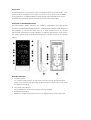
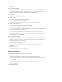
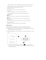
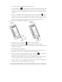
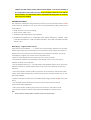
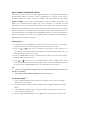
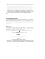
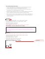
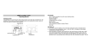
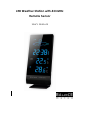
LED Weather Station with 433 MHz
Remote Sensor
User’s Manual
Introduction
Congratulations on your purchase of this new Weather Station with LED display. This
unique product is designed for everyday use for the home or office and is a definite
asset of great use. To fully benefit from all the features and understand the correct
operation of this product, please read this instruction manual thoroughly.
FUNCTIONS OF THE WEATHER STATION
This LED weather station measures the ambient temperature and atmospheric
pressure for weather forecasting. Moreover, equipped with a 433MHz radio frequency
(RF) interface, it can receive data from up to three remote sensors for outdoor
temperature measurement within a distance of 100 feet (30 meters) in open space.
The data is continuously updated and displayed on the LED panel of the weather
station.
FEATURES: MAIN UNIT
A. IR motion sensor
It is a motion sensing device to activate the snooze function, provided that an
object (e.g. human hand) gets within an 8cm distance in front of the sensor, when
the alarm is activating.
B. Air pressure trend arrows
It is to indicate the trend of atmospheric pressure changes
C. Weather forecast icon
Display the weather-forecast icons for sunny, slightly cloudy, cloudy, rainy and
stormy.
D. Low battery indicator
It is to indicate the backup battery in the main unit when the battery power level is
low. The user needs to change the batteries at once. Otherwise, the clock and
alarm setting will be reset if the plug-in adaptor is disconnected.
E. Clock time
Display current time or alarm time
F.
Alarm on icon
It is shown when the daily alarm is enabled.
G. Radio controlled clock time indicator
Appears to indicate the displayed clock time is a received RCC time
H. Indoor temperature icon
It is to indicate the indoor temperature is displayed
I.
Indoor maximum/minimum temperature icon
It is to indicate the maximum/minimum indoor temperature that is being displayed
J.
Remote sensor battery low indicator
It is shown when the batteries of the remote sensor are running low and the
temperature measured by this sensor is no longer reliable. The user must change
the batteries as soon as possible.
K. Remote sensor indicator
Indicates which channel of remote sensor is being displayed. It can display up to 3
different remote sensors which are in different locations and within 100 feet (30
meters) distance from the main unit.
L.
Outdoor maximum/minimum icon
It is to indicate the maximum/minimum outdoor temperature that is being
displayed
M. Wall mounting hole
For wall-mounting of the weather station
DESCRIPTION OF BUTTONS
The LED weather station has 8 buttons on the rear side
1. [ ] button
- Press once to switch from clock mode to alarm time display mode
- While in alarm display mode, press once to toggle between enable or disable
the daily alarm
- While in alarm display mode, press and hold for 2 seconds to enter
alarm setting mode
2. [MAX/MIN] button
- Toggle to display the Max/Min reading of the Indoor & Remote Temperature.
- Press & hold for 2 seconds to clear the memorized Max/Min readings of the
Indoor channel or the selected remote channel.
3. [MENU/SETUP] button
Press and hold 2 seconds to enter clock setting mode
4. [CH] button
- Select among channel 1, 2, 3 or to enter auto scroll mode.
- Press and hold for 2 seconds to activate or deactivate the sensor
searching mode
5. [ ] button
Press once to increase the setting in CLOCK or ALARM setting mode
6. [
] button
Press once to decrease the setting in CLOCK or ALARM setting mode
7. [RESET] button
Press once to trigger system reset and restore the factory default setting.
8. [BRIGHT/DIM] button
Toggle to select a bright LED display or a dim LED display
GETTING STARTED
This Weather Station was designed for easy set up. The following steps are
recommended for installation of the remote sensor and the weather station.
1.
Install batteries in the remote sensor(s) prior to backup batteries and AC/DC
adaptor installation in the weather station.
2.
The following diagrams and steps illustrate the battery installation for remote
sensor
Open the battery compartment at the bottom
of the outdoor sensor.
Install 2 pieces of AA size batteries according to the polarity mark inside the
battery compartment.
Close the battery compartment of outdoor sensor.
The transmission LED
on the front of the outdoor sensor will start to flash for
10 seconds. The default flashing frequency is once per around 2 seconds to
indicate this sensor will be registered on channel 1 if not set manually within 10
seconds.
While the transmission LED is flashing, press once the [CH] button
at the
bottom of a remote sensor and it will flash twice per around 2 seconds to
indicate this sensor will be registered on channel 2. Keep toggle on [CH]
button can change channel setting up to 3 and then back to channel 1.
3.
Backup battery and adaptor installation for main unit
Take away the removable stand
from the weather station.
Open the battery compartment
on the rear of the weather station.
Install 2 pieces of AAA sized batteries according to the polarity mark inside the
battery compartment.
Close the battery compartment
Put back the removable stand and place the weather station securely on a
flat surface; or mount it on a wall without the removable stand
Insert the plug of the AC/DC adapter into the DC 5V IN jack
of the weather
station and connect the adaptor to a wall outlet (100-240V AC).
When the weather station is powered on, it will initiate the RF search mode to
search if there is/are any remote sensor(s) within 100 feet (30 meters).
Once a remote sensor is registered, this LED weather station will display its
temperature in the corresponding remote channel.
Note: This LED weather station must work with the adaptor. If the user removes the
adaptor, the LED weather station will turn off the display, save the last reading of
the temperature and weather forecast; keep running the internal clock with the
backup battery. The LED weather station will start RF searching mode for 2 minute
after plug in the adaptor.
TRANSMISSION RANGE
The maximum transmission range between remote sensor and weather station is 30m
under optimum conditions in an open area. The actual distance will be reduced by
many factors:
Walls, reinforced concrete ceilings
Trees, bushes, earth, rocks
Metal & conducting objects (e.g. radiators)
Broadband interferences in residential areas (DECT telephones, mobiles, radio
controlled headphones, radio-controlled speakers, other radio-controlled weather
stations, etc.)
Manually (re-) register remote sensors
If the remote sensor displays ‘--,-‘, it means the communication between the weather
station and remote sensor is interrupted over 35 minutes. Firstly, please check the low
battery icon in the remote sensor and replace the batteries if necessary. Secondly,
manually (re-) register your remote sensor with below steps.
• Remove the batteries from the remote sensor for a few seconds.
• Re-install the batteries. The transmission LED will flash once every 2 seconds to
indicate channel one is selected.
• Set the desired channel
Note 1.
The transmission LED will flash twice every 2 seconds to
indicate channel 2 is selected; flash thrice every 2 seconds to indicate channel 3 is
selected.
• Press and hold the weather station [CH] button for 2 seconds to activate RF search
mode. There will be a brief beep and the remote sensor channel number (1-3) on the
LED panel will flash.
• Make sure that the remote sensor is installed within range (maximum 30m in an open
area).
• The weather station will detect the remote sensor and the remote sensor
temperature will be displayed.
• Press and hold the weather [CH] button for 2 seconds to exit search mode.
• If no button is pressed, search mode will automatically stop after 2 minutes.
Note:
1.
Please refer to the “Getting started” section for remote sensor channel setup.
DCF 77 RADIO CONTROLLED CLOCK
The remote sensor receives the time signal transmitted by Physikalisch-Technische
Bundesanstalt (PTB) of Germany, which is regulated by 4 atomic clocks and in
average deviates less than 1 second in 2 million years. PTB transmits the time signal
(DCF77, 77.5kHz) continuously from Mainflingen, 25 km southeast of Frankfurt (am
Main). It is expected that the signal can cover a distance of 1,500 km from the
transmitter. Then the remote sensor transmits the time signal to the weather station to
display the accurate time. However, there are many environment factors may affect
the RCC reception, i.e. nearby computer monitors or other electronic devices, put on
any metal surface, surrounded by any tall buildings and so on. The user had better to
place the remote sensor away from metallic structures and face the transmitter in
Mainflingen-near Frankfurt, Germany.
SET THE CLOCK Note 2
1. Press and hold the [MENU/SETUP] button for more than 2 seconds to enter clock
setting mode, the hour value begins flashing at the frequency of 1Hz.
2. Press the [ ] or [
] button once to increase or decrease the hour value by one
hour. Hold down either button will initiate fast increment/decrement (with 10
increments/decrements per second).
3. Press the [MENU/SETUP] button to confirm the hour value. The minute value begins
flashing at the frequency of 1Hz.
4. Press [ ] or [
] button to set your desired minute value. Holding down either
button will initiate fast increment/decrement (with 10 increments/decrements per
second). Press the [MENU/SETUP] button to confirm the minute value. Note 3
Note:
2.
If there is no key pressed in the setting mode for 10 seconds, it will automatically save the set value
and exit to normal display.
3.
Every change of minute digit will automatically reset the seconds to zero.
TO SET DAILY ALARM Note 4
1. In the clock time display mode, press the [ ] button once to switch to display
alarm time for 10 seconds.
2. Press the [ ] button again in alarm display mode to enable or disable the daily
alarm.
3. In the alarm time display mode, press and hold the [ ] button for 2 seconds to
enter the alarm setting mode.
4. The hour digits will be flashing, use the [ ] button to increase by one hour or the
] button to decrease by one hour to the desired hours. Holding down the button
will initiate the fast increments/decrements. Press the [ ] button to confirm.
5. The minute digits will be flashing. Use the [ ] button to increase by one minute or
the [ ] button to decrease by one minute to the desired minutes. Holding down
the button will initiate the fast increments/decrements. Press the [ ] button to
confirm and exit the alarm setting mode. The unit will show the alarm time for 10
seconds and exit to clock time display automatically. The alarm bell icon
will be
turned on in clock time display to indicate that the daily alarm is enabled.
Note:
4.
If there is no key pressed in the setting mode for 10 seconds, it will automatically save the set value
and exit to normal display.
TO ACITVATE THE SNOOZE FUNCTION
In the top middle of the weather station, there is an IR motion sensor which can
activate snooze function. When the alarm sounds, move your hand in front of the IR
motion sensor within a distance of 8cm to pause alarm and activate snooze function.
The alarm bell icon
will keep flashing during the 5 minutes snooze time. Press any
key to exit snooze.
Weather forecast
The weather station forecasts the weather condition for the next 12~24 hours based
on the ambient air pressure changes. There are 5 kinds of forecasted weather
conditions: Sunny, Slightly cloudy, Cloudy, Rainy and Stormy.
The air pressure arrow displayed on the LED shows the air pressure change trend:
The weather condition is expected to be better.
The weather condition is expected to be worse.
The weather condition remains unchanged.
The accuracy of a general pressure-based weather forecast is about 70 to 75%,
and therefore, we cannot be held responsible for any inconveniences so caused
by an inaccurate weather forecast.
The weather forecast is meant for the next 12 to 24 hours. It may not necessarily
reflect the current weather condition.
The “Sunny” forecast covering night hours indicates clear weather
How to display Max/Min temperature
Press the [MAX/MIN] button to display the memorized maximum indoor and
outdoor temperature on the channel displayed for 6 seconds.
Press this key again to display the memorized minimum indoor and outdoor
temperature on the channel displayed for 6 seconds.
While the maximum/minimum value on one channel is displayed, press the [CH]
button to display the maximum/minimum values on another channel.
When maximum/minimum value is displayed, press and hold the [MAX/MIN] for 2
seconds to clear the memorized max/min values in this channel and display the
current temperature.
Specifications
Main Unit (275523)
Displayed IN temperature range : -10°C to +60.0°C (14°F to 140.0°F)
Operating temperature range : 0°C to +50.0°C (32.0°F - 122.0°F)
Temperature resolution : 0.1°C (0.2°F)
Remote Temperature measurement
Displayed OUT temperature range : -20.0°C to +60.0°C (-4.0°F to 140.0°F)
Backup batteries : Use 2 pieces UM-4 AAA size 1.5V battery
Caution:
. Under severe radio frequency interference, the unit may not establish or maintain
communication link in this condition. It will return to normal state until the RF interference
does not exist.
Remote Unit
Displayed temperature range : -20.0°C to +60.0°C (-4.0°F to 140.0°F)
Operating temperature range : -10.0°C to +50.0°C (14.0°F to 122.0°F)
Temperature resolution : 0.1°C (0.2°F)
RF Transmission Frequency : 433 MHz
RF Transmission Range : 30 meters in open area
Temperature sensing cycle : 60 - 75 seconds
Batteries: 2 pieces of UM-4 AA size 1.5V battery
Verwijderd: A