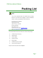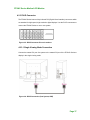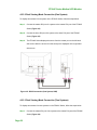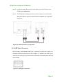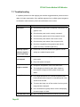
1
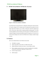
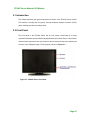
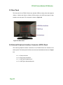
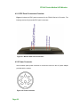
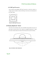
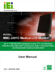
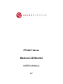
FP304C Series Medical LCD Monitor FP304C Series Medical LCD Monitor USER’S MANUAL 30” FP304C Series Medical LCD Monitor Revision Date Version Changes 2007-10 1.00 Initial Release Page 3 FP304C Series Medical LCD Monitor Copyright COPYRIGHT NOTICE The information in this document is subject to change without prior notice in order to improve reliability, design and function and does not represent a commitment on the part of the manufacturer. In no event will the manufacturer be liable for direct, indirect, special, incidental, or consequential damages arising out of the use or inability to use the product or documentation, even if advised of the possibility of such damages. This document contains proprietary information protected by copyright. All rights are reserved. No part of this manual may be reproduced by any mechanical, electronic, or other means in any form without prior written permission of the manufacturer. TRADEMARKS All registered trademarks and product names mentioned herein are used for identification purposes only and may be trademarks and/or registered trademarks of their respective owners. Page 4 FP304C Series Medical LCD Monitor Manual Conventions WARNING! Warnings appear where overlooked details may cause damage to the equipment or result in personal injury. Warnings should be taken seriously. Warnings are easy to recognize. The word “warning” is written as “WARNING,” both capitalized and bold and is followed by text. The text is the warning message. A warning message is shown below: WARNING: This is an example of a warning message. Failure to adhere to warning messages may result in permanent damage to the FP304C Series or personal injury to the user. Please take warning messages seriously. CAUTION! Cautionary messages should also be heeded to help reduce the chance of losing data or damaging the FP304C Series. Cautions are easy to recognize. The word “caution” is written as “CAUTION,” both capitalized and bold and is followed. The italicized text is the cautionary message. A caution message is shown below: Page 5 FP304C Series Medical LCD Monitor CAUTION: This is an example of a caution message. Failure to adhere to cautions messages may result in permanent damage to the FP304C Series. Please take caution messages seriously. NOTE: These messages inform the reader of essential but non-critical information. These messages should be read carefully as any directions or instructions contained therein can help avoid making mistakes. Notes are easy to recognize. The word “note” is written as “NOTE,” both capitalized and bold and is followed by text. The text is the cautionary message. A note message is shown below: NOTE: This is an example of a note message. Notes should always be read. Notes contain critical information about the FP304C Series. Please take note messages seriously. Page 6 FP304C Series Medical LCD Monitor Packing List NOTE: If any of the components listed in the checklist below are missing, please do not proceed with the installation. Contact the Richardson reseller or vendor you purchased the FP304C Series from. RICHARDSON ELECTRONICS Display Systems Group 12975 16th Ave. N., Suite 300 Plymouth, MN 55441 Sales: 888-735-7373 TEKLINK Technical Support: www.teklink.rell.com Web: www.imagesystemscorp.com The items listed below should all be included in the FP304C Series package. 1 x FP304C Series LCD monitor 1 x Monitor stand 1 x Power adapter 1 x Power cord (US) 2 x DVI-D cables 1 x USB cable (Type A to Type B) 1 x User manual and utility CD Images of the above items are shown in Chapter 3. Page 7 FP304C Series Medical LCD Monitor Safety Precautions Prior to installing, moving and modifying the monitor, make sure the power is turned off and the power cord is disconnected. Do not apply voltage levels that exceed the specified voltage range. Doing so will cause fire or an electric shock. Electric shocks can occur if the panel is opened. Do not drop or insert any object into the ventilation openings of the monitor. Only qualified engineers from certified system integrators are allowed to make necessary functional modifications to the monitor. If considerable amount of dust, water or fluids entered the monitor, turn off the power supply immediately, unplug the power cord and contact the monitor vendor. Explosions may occur with installations in environments where flammable gases are present. Grounding reliability can only be achieved when the equipment is connected to an equivalent receptacle marked “Hospital Only” or “Hospital Grade”. This device is intended to be used: (1) outside a “patient vicinity” area or (2) within a “patient vicinity” area such as consulting rooms. The signal input parts or signal output parts (SIP/SOP) need to be connected properly and any unused SIP/SOP shall not be accessible to unqualified personnel after the LCD is integrated into a medical system. The unit is for exclusive interconnection with IEC 60XXX certified equipment outside of patient environment and IEC 60601-1 certified equipment inside the patient environment. This device complies with EN60601-1-2. To minimize the interference from other equipment, a minimum 0.5 m distance shall be kept from other potential electromagnetic sources, such as cell phones, etc. Equipment connected to the analog or digital interfaces must comply with the respective IEC standards (e.g. IEC 60950 for data processing equipment and IEC 60601-1 for medical equipment). Page 8 FP304C Series Medical LCD Monitor To fully disengage power to the unit, disconnect the power cord from its AC outlet. Do not remove any of the display housings. There are no user serviceable parts inside the monitor. Refer servicing to qualified service personnel. All configurations shall comply with the current version of the IEC 60601-1-1 safety requirements for medical electrical systems. To maintain the highest level of performance, it is recommended that this product be replaced after five years of use. FURTHER PRECAUTIONS Do not drop the monitor against a hard surface. Doing so will damage the display. Do not strike or exert excessive force onto the panel. Touching the LCD panel using a sharp object will cause damage to the display. Avoid environments exposed to direct sunlight, dust or chemical vapors. The ambient temperature of the installation site should be observed and controlled to avoid overheating the monitor. Condensation might form inside of the monitor chassis if exposed to sudden changes in temperature. Carefully route the power cord, so that people cannot step on it. Do not place anything over the power cord or bend it. If the equipment should be left unused for an extended period of time, disconnect it from the power source to avoid damage by transient over-voltage. If any of the following situations arise, have the equipment checked by qualified service personnel: o o o o The power cord or plug is damaged. Liquid has penetrated into the equipment. The equipment has been exposed to moisture. The equipment does not work properly, or cannot be made to work according to the user manual. o o The equipment has been dropped and damaged. The equipment shows obvious signs of damage. Page 9 FP304C Series Medical LCD Monitor WARNING: Any changes or modifications made to the equipment that are not expressly approved by the relevant standards could void the authority to operate the equipment. ADDITIONAL INFORMATION AND ASSISTANCE MAINTENANCE AND CLEANING Prior to cleaning any part or component of the monitor, please read the details below. Except for the properly installed front LCD panel, never spray or squirt liquids directly onto any other component. To clean the front panel, please rub it with a piece of soft dry cloth or a slightly moistened cloth. The interior of the LCD monitor does not require cleaning. Keep fluids away from the LCD monitor interior. Be cautious of all small removable components when vacuuming the monitor. Turn the system off before cleaning the LCD monitor. Never drop any objects or liquids through the openings of the LCD monitor. Be cautious of any possible allergic reactions to solvents or chemicals used when cleaning the monitor. Page 10 Avoid eating, drinking and smoking within vicinity of the monitor. FP304C Series Medical LCD Monitor CLEANING TOOLS Some components in the monitor may only be cleaned using a product specifically designed for the purpose. In such case, the product will be explicitly mentioned in the cleaning tips. Below is a list of items to use when cleaning the computer or computer peripherals. Cloth – Although paper towels or tissues can be used, a soft, clean piece of dry cloth is recommended when cleaning the monitor. Using solvents – The use of solvents is not recommended when cleaning the monitor as they may damage the plastic parts. Vacuum cleaner – Using a vacuum specifically designed for computers is one of the best methods of cleaning the monitor. Over dust and dirt can restrict the airflow in a computer and cause circuitry to corrode. Cotton swabs - Cotton swaps moistened with rubbing alcohol are excellent tools for wiping hard to reach areas. Foam swabs - Whenever possible, it is best to use lint free swabs such as foam swabs for cleaning. ESD PRECAUTIONS Observe all conventional anti-ESD methods while handling the components contained within the LCD should the need arise for adding a functionality. The use of a grounded wrist strap and an anti-static work pad is recommended. Avoid dust and debris or other static-accumulating materials in the work area. Page 11 FP304C Series Medical LCD Monitor PRODUCT DISPOSAL Within the United States: The lamps in this product contain mercury. Please dispose according to state, local or Federal law. Within the European Union: EU-wide legislation, as implemented in each Member State, requires that waste electrical and electronic products carrying the mark (left) must be disposed of separately from normal household waste. This includes monitors and electrical accessories, such as signal cables or power cords. When you need to dispose of your display products, please follow the guidance of your local authority, or ask the shop where you purchased the product. The mark on electrical and electronic products only applies to the current European Union Member States. Page 12 Please follow the national guidelines for electrical and electronic product disposal. FP304C Series Medical LCD Monitor Table of Contents 1 INTRODUCTION................................................................................................... 18 1.1 FP304C SERIES MEDICAL LCD MONITOR OVERVIEW ............................................. 19 1.2 FEATURES ................................................................................................................. 19 1.3 COMPATIBLE GRAPHICS CARD ................................................................................. 20 1.4 MODEL VARIATIONS ................................................................................................. 20 1.5 GENERAL SPECIFICATIONS ....................................................................................... 20 1.5.1 FP304C Series Monitor ................................................................................... 20 1.5.2 Classification ................................................................................................... 22 1.6 INTERNATIONAL STANDARDS COMPLIANCE ............................................................. 22 2 MECHANICAL OVERVIEW ............................................................................... 24 2.1 INTRODUCTION......................................................................................................... 25 2.2 FRONT PANEL ........................................................................................................... 25 2.3 REAR PANEL ............................................................................................................. 26 2.4 EXTERNAL PERIPHERAL INTERFACE CONNECTOR (EPIC) PANEL ............................. 26 2.5 PHYSICAL DIMENSIONS ............................................................................................ 28 3 UNPACKING .......................................................................................................... 30 3.1 UNPACKING .............................................................................................................. 31 3.1.1 Unpacking Precautions.................................................................................... 31 3.1.2 Packing List ..................................................................................................... 31 4 INSTALLATION .................................................................................................... 34 4.1 INSTALLATION PRECAUTIONS ................................................................................... 35 4.2 EXTERNAL PERIPHERAL INTERFACE CONNECTORS ................................................... 35 4.2.1 EPIC Panel Connectors Overview................................................................... 36 4.2.2 Power Connector ............................................................................................. 36 4.2.3 DVI-D Connector............................................................................................. 37 4.2.3.1 Single Viewing Mode Connection ............................................................ 37 4.2.3.2 Dual Viewing Mode Connection (One System) ....................................... 38 4.2.3.3 Dual Viewing Mode Connection (Two Systems) ..................................... 38 Page 13 FP304C Series Medical LCD Monitor 4.2.4 USB Type A Connector..................................................................................... 39 4.2.5 USB Type B Connector .................................................................................... 40 4.3 DISPLAY ADJUSTMENT - SWIVEL .............................................................................. 40 4.4 MOUNTING THE FP304C SERIES LCD MONITOR ..................................................... 41 4.4.1 Monitor Arm or Stand Installation................................................................... 41 5 ON-SCREEN-DISPLAY (OSD) CONTROLS ..................................................... 44 5.1 USER MODE OSD STRUCTURE ................................................................................. 45 5.1.1 OSD Buttons..................................................................................................... 45 5.1.2 OSD Menu Structure ........................................................................................ 46 5.2 USING THE OSD....................................................................................................... 48 5.2.1 Entering, Exiting and Switching OSD Menus.................................................. 48 5.2.2 Selecting and Setting Adjustments ................................................................... 48 5.3 OSD MENU OPTIONS ............................................................................................... 48 5.3.1 Brightness Menu .............................................................................................. 48 5.3.2 Resolution Menu .............................................................................................. 49 5.3.3 Color/Gray Menu............................................................................................. 49 5.3.3.1 Single Viewing Mode (4MP) .................................................................... 49 5.3.3.2 Dual Viewing Mode (2MP)....................................................................... 50 5.3.4 Gamma Menu................................................................................................... 51 5.3.4.1 Mono Display............................................................................................ 51 5.3.4.2 Color Display ............................................................................................ 52 5.3.4.3 Dual Display (2MP).................................................................................. 53 5.3.5 Information Menu ............................................................................................ 53 5.3.6 System Initialization Menu............................................................................... 55 6 SOFTWARE DRIVER ........................................................................................... 57 6.1 AVAILABLE SOFTWARE DRIVERS .............................................................................. 58 6.2 USB DRIVER INSTALLATION .................................................................................... 58 6.3 CALIBRATION SOFTWARE ......................................................................................... 59 7 TROUBLESHOOTING ......................................................................................... 61 7.1 TROUBLESHOOTING.................................................................................................. 62 A INTERNATIONAL STANDARDS COMPLIANCE ........................................... 65 A.1 UL 60601-1 AND CAN/CSA C22.2 NO. 601.1...................................................... 66 Page 14 FP304C Series Medical LCD Monitor A.2 93/42/EEC, EN60601-1, EN60601-2 ..................................................................... 66 A.3 FCC ........................................................................................................................ 66 A.4 ROHS COMPLIANT .................................................................................................. 66 A.5 ATTENTION .............................................................................................................. 67 B GLOSSARY............................................................................................................. 68 INDEX.............................................................................................................................. 73 Page 15 FP304C Series Medical LCD Monitor List of Figures Figure 1-1: FP304C Series Medical LCD Monitor .........................................................19 Figure 2-1: FP304C Series Front View...........................................................................25 Figure 2-2: Rear Panel.....................................................................................................26 Figure 2-3: EPIC Panel ....................................................................................................27 Figure 2-4: EPIC Symbols...............................................................................................27 Figure 4-1: Monitor EPIC Panel Connectors.................................................................36 Figure 4-2: Power Connector .........................................................................................36 Figure 4-3: DVI-D Connector Pinout Locations ............................................................37 Figure 4-4: DVI-D Connection (One System, 4MP).......................................................37 Figure 4-5: DVI-D Connection (One System, 2MP).......................................................38 Figure 4-6: DVI-D Connection (Two Systems) ..............................................................39 Figure 4-7: USB Type A Connector................................................................................39 Figure 4-8: USB Type B Connector................................................................................40 Figure 4-9: Monitor Swivel Adjustment.........................................................................40 Figure 4-10: VESA Mounting Holes ...............................................................................41 Figure 5-1: OSD Control Buttons ...................................................................................45 Figure 5-2: Brightness Menu ..........................................................................................48 Figure 5-3: Resolution Menu ..........................................................................................49 Figure 5-4: Color/Gray Menu (4MP) ...............................................................................50 Figure 5-5: Color/Gray Menu (2MP) ...............................................................................50 Figure 5-6: Gamma Menu (Mono Display).....................................................................51 Figure 5-7: Gamma Menu (Color Display) .....................................................................52 Figure 5-8: Gamma Menu (Dual Display) ......................................................................53 Figure 5-9: Information Menu .........................................................................................54 Figure 5-10: System Initialization Menu ........................................................................55 Figure 6-1: Install Driver Screen ......................................... Error! Bookmark not defined. Figure 6-2: Installation Successful Screen ........................ Error! Bookmark not defined. Page 16 FP304C Series Medical LCD Monitor List of Tables Table 1-1: Model Variations ............................................................................................20 Table 1-2: FP304C Series Monitor Specifications ........................................................22 Table 2-1: Physical Dimensions.....................................................................................28 Table 3-1: Package List Contents ..................................................................................32 Table 5-1: OSD Menus.....................................................................................................47 Table 5-2: Information Menu – Item Description ..........................................................54 Table 7-1: Troubleshooting ............................................................................................63 Page 17 FP304C Series Medical LCD Monitor Chapter 1 1 Introduction Page 18 FP304C Series Medical LCD Monitor 1.1 FP304C Series Medical LCD Monitor Overview Figure 1-1: FP304C Series Medical LCD Monitor The FP304C Series is a high performance, 4 Megapixel medical grade monochrome/color LCD monitor designed for the exacting needs of professionals that provides clear and sharp images with resolutions of up to 2560 x 1600 pixels, 300 cd/m2 brightness and 1000:1 contrast ratio, making it ideal for diagnosing detailed medical graphics. The VESA mounting capabilities provide a wide array of mounting options. The FP304C Series can be configured to display in seamless dual 2MP through two DVI signal inputs. The built-in front sensor and the backlight sensor ensure the FP304C Series to display consistent images over time. 1.2 Features Some of the standard features of the FP304C Series include: VESA DDC/CI compliant Supports single 4MP viewing mode or dual 2MP viewing mode Supports Windows Vista deep color feature, 10-bit and higher for RGB. Built-in backlight controller with sensor to detect the brightness of the backlight module and to automatically compensate for aging over time. Dual DVI-D digital interfaces USB hub support Page 19 FP304C Series Medical LCD Monitor Wide viewing angle (right/left: 178°, up/down: 178°) Full screen availability Slim bezel Standard VESA mounting interface (100mm x 100mm or 100mm x 200mm) Various graphics card support: Matrox, RealVision, ATI, nVidia and other high-level commercial cards 1.3 Compatible Graphics Card FP304C Series supports the following graphics cards in either Single 4MP Viewing Mode or Dual 2MP Viewing Mode: nVidia QUADRO FX Series ATI FireGL Series 1.4 Model Variations The FP304C Series has the following base models. Model Size Mono/Color Pixels Front Panel Protection FP304C 30.0" Mono/Color 4M IPX0 FP304CA 30.0" Mono/Color 4M IPX2 Table 1-1: Model Variations 1.5 General Specifications The following sections describe the FP304C Series medical LCD monitor, LCD panel and power adapter specifications. 1.5.1 FP304C Series Monitor Table 1-2 lists the specifications for the FP304C Series medical LCD monitor. Model Page 20 FP304C/FP304CA FP304C Series Medical LCD Monitor Drive System a-Si TFT active matrix Display area (H x V) 641.3mm x 400.8mm Diagonal size of display 75.6cm (30.0 inches) Resolution (H x V) 2560 x 1600 Display color 16,777,216 colors Pixel pitch (H x V) 0.2505mm x 0.2505mm Sub-pixel pitch (H x V) 0.0835mm x 0.2505mm Pixel format RGB (Red dot, Green dot, Blue dot) vertical stripe Luminance-max. 300 (cd/m2) Max. Luminance 220 (cd/m2) for FP304C (calibrated) 200 (cd/m2) for FP304CA Contrast ratio 1000:1 (typ.) Viewing angle Right 178o, Left 178o, Up 178o, Down 178o Response time (Ton + Toff) 12ms (typ.) Polarizer surface/hardness Antiglare/3H Backlight 16 CCFL Default gamma Gamma 2.2 LUT 10-bit for each RGB Signal input Dual link DVI-D (digital) USB 2.0 hub 1 upstream/2 downstream OSD Keypad Yes (rear panel) Power Adapter Input voltage range Power Adapter Input frequency range Power Adapter Max. Input AC current Power Adapter Power output 100VAC-240VAC 47Hz-63Hz 2.0Arms @ 90V AC 24VDC, 6.25A, 150W (max.) Physical dimensions With stand: 522mm x 736mm x 266mm (landscape) (H x W x D) Without stand: 480mm x 736mm x 76mm (landscape) Weight (without/with stand) 12.79kg/16.55kg Operating temperature +10°C ~ +35°C Storage temperature 0°C ~ +45°C Page 21 FP304C Series Medical LCD Monitor Operation Relative Humidity Storage/Transportation Relative Humidity Approvals 30% ~ 75% Non-condensing 10% ~ 95% Non-condensing UL60601-1, EN60601-1-1, EN60601-1-2, FCC Parts 15 Table 1-2: FP304C Series Monitor Specifications 1.5.2 Classification Power by Class I power adapter: No Applied Part. Protection against the ingress of water: o o FP304C: IPX0 FP304CA: IPX2 Mode of operation: Continuous Operation The equipment not suitable for use in the presence of a flammable anesthetic mixture with air or with oxygen or nitrous oxide: Not AP or APG Category: 1.6 International Standards Compliance The FP304C series LCD monitor complies with the following international standards: UL 60601-1 AND CAN/CSA C22.2 NO. 601.1 93/42/EEC, EN60601-1, EN60601-2 FCC RoHS For a more detailed description of these standards, please refer to Appendix A. Page 22 FP304C Series Medical LCD Monitor THIS PAGE IS INTENTIONALLY LEFT BLANK Page 23 FP304C Series Medical LCD Monitor Chapter 2 2 Mechanical Overview Page 24 FP304C Series Medical LCD Monitor 2.1 Introduction This chapter describes the general mechanical overview of the FP304C Series medical LCD monitors, including the front panel, external peripheral interface connector (EPIC) panel, available interfaces and dimensions. 2.2 Front Panel The front panel of the FP304C Series has an LCD screen surrounded by a sturdy acrylonitrile butadiene styrene (ABS) and polycarbonate (PC) plastic frame. A front sensor and an ambient light sensor are also located on the front panel to ensure the stability and accuracy of the displayed image. The front panel is shown in Figure 2-1. Figure 2-1: FP304C Series Front View Page 25 FP304C Series Medical LCD Monitor 2.3 Rear Panel The rear panel of the FP304C Series has standard VESA mounting holes that supports 100mm x 100mm and 100mm x 200mm VESA mounting. An OSD control panel is also located on the rear panel. The rear panel is shown in Figure 2-2. Figure 2-2: Rear Panel 2.4 External Peripheral Interface Connector (EPIC) Panel The external peripheral interface connectors of the FP304C Series are located on the bottom panel. The bottom panel interface connectors are listed below and shown in Figure 2-3. Page 26 1 x Power connector 2 x DVI-D input connectors 1 x USB Type B upstream port 2 x USB Type A downstream ports FP304C Series Medical LCD Monitor Figure 2-3: EPIC Panel The EPIC connectors on the bottom panel can easily be distinguished by the connector symbols shown on the rear panel (Figure 2-4). Figure 2-4: EPIC Symbols Page 27 FP304C Series Medical LCD Monitor 2.5 Physical Dimensions The physical dimensions of the FP304C Series monitors are specified in Table 2-1 below. Landscape Orientation Landscape Orientation Without Stand With Stand Width (mm) 736 736 Height (mm) 480 522 Depth (mm) 76 266 Table 2-1: Physical Dimensions Page 28 FP304C Series Medical LCD Monitor THIS PAGE IS INTENTIONALLY LEFT BLANK Page 29 FP304C Series Medical LCD Monitor Chapter 3 3 Unpacking Page 30 FP304C Series Medical LCD Monitor 3.1 Unpacking 3.1.1 Unpacking Precautions When the FP304C Series is unpacked, please do the following: Make sure the packing box is facing upwards so the FP304C Series does not fall out of the box. Make sure all the components shown in Section 3.1.2 are present. 3.1.2 Packing List NOTE: If some of the components listed in the checklist below are missing, please do not proceed with the installation. Contact the Richardson reseller or vendor you purchased the FP304 series from or contact a Richardson sales representative directly. When the FP304C Series medical LCD monitor is received, make sure all the components listed below are present. Quantity 1 1 2 Item Image FP304C Series LCD monitor USB Series A to USB Series B cable DVI cable Page 31 FP304C Series Medical LCD Monitor 1 AC power adapter 1 AC power cable (US) 1 Utility CD Table 3-1: Package List Contents Page 32 FP304C Series Medical LCD Monitor THIS PAGE IS INTENTIONALLY LEFT BLANK Page 33 FP304C Series Medical LCD Monitor Chapter 4 4 Installation Page 34 FP304C Series Medical LCD Monitor 4.1 Installation Precautions When installing the FP304C Series medical LCD monitor, please follow the precautions listed below: Read the user manual: The user manual provides a complete description of the FP304C Series medical LCD monitor, installation instructions and configuration options. DANGER! Disconnect Power: Power to the monitor must be disconnected when installing the FP304C Series medical LCD monitor. Electric shock and personal injury might occur if the rear panel of the monitor is accessed while the power cord is still connected to an electrical outlet. Qualified Personnel: The FP304C Series medical LCD monitor must be installed and operated only by trained and qualified personnel. Maintenance, upgrades, or repairs may only be carried out by qualified personnel who are familiar with the associated dangers. Mounting: The monitor is a heavy piece of equipment. Please ensure at least two people assist with mounting the monitor. Air Circulation: Make sure there is sufficient air circulation when installing the monitor. The monitor’s cooling vents must not be obstructed by any objects. Blocking the vents can cause overheating of the monitor. 4.2 External Peripheral Interface Connectors The external peripheral interface panel connectors for the FP304C Series medical LCD monitors are listed below. 1 x Power connector 2 x DVI-D input connectors 1 x USB Type B upstream port 2 x USB Type A downstream ports Page 35 FP304C Series Medical LCD Monitor 4.2.1 EPIC Panel Connectors Overview Figure 4-1 shows the EPIC panel connectors for the FP304C Series LCD monitor. The following sections fully describe EPIC panel connectors. Figure 4-1: Monitor EPIC Panel Connectors 4.2.2 Power Connector Use the bottom panel power connector to connect the monitor to the AC power adapter provided with the monitor. Figure 4-2: Power Connector Page 36 FP304C Series Medical LCD Monitor 4.2.3 DVI-D Connector The FP304C Series has two 24-pin female DVI (Digital Visual Interface) connectors which are standard for high-speed, high-resolution digital displays. Use the DVI-D connectors to connect the FP304C Series to one or two system. Figure 4-3: DVI-D Connector Pin-out Locations 4.2.3.1 Single Viewing Mode Connection Connect the master DVI port of a system to the master DVI port of the FP304C Series to display in the single viewing mode. Figure 4-4: DVI-D Connection (One System, 4MP) Page 37 FP304C Series Medical LCD Monitor 4.2.3.2 Dual Viewing Mode Connection (One System) To display two screens from a system on the FP304C Series, follow the steps below. Step 1: Connect the master DVI port of a system to the master DVI port of the FP304C Series (Figure 4-5). Step 2: Connect the slave DVI port of a system to the slave DVI port of the FP304C Series (Figure 4-5). Step 3: The FP304C Series displays the source from the master port on the left hand side screen while the source from the slave port is displayed on the right hand side screen. Step 0: Figure 4-5: DVI-D Connection (One System, 2MP) 4.2.3.3 Dual Viewing Mode Connection (Two Systems) To display two screens from two systems on the FP304C Series, follow the steps below. Step 1: Connect the master DVI port of one system to the master DVI port of the FP304C Series (Figure 4-6). Page 38 FP304C Series Medical LCD Monitor Step 2: Connect the master DVI port of the other system to the slave DVI port of the FP304C Series (Figure 4-6). Step 3: The FP304C Series displays the source from the master port on the left hand side screen while the source from the slave port is displayed on the right hand side screen. Step 0: Figure 4-6: DVI-D Connection (Two Systems) 4.2.4 USB Type A Connector Use the bottom panel standard USB Type A connector to connect the monitor to a secondary USB device aside from the main computer. To enable the two USB Type A connectors, the USB Type B connector must be connected to a computer system with USB driver installed. Figure 4-7: USB Type A Connector Page 39 FP304C Series Medical LCD Monitor 4.2.5 USB Type B Connector Use the bottom panel standard USB Type B connector to connect the monitor to a computer system to enable the other two USB Type A connectors on the bottom panel of the FP304C Series. Figure 4-8: USB Type B Connector 4.3 Display Adjustment - Swivel The monitor can be swiveled to offer a more comfortable viewing position to the user. The total range of movement is 90° (45° left or right from a straightforward position). To adjust the monitor, hold both sides of the monitor bezel and swivel left or right as necessary. Figure 4-9: Monitor Swivel Adjustment Page 40 FP304C Series Medical LCD Monitor 4.4 Mounting the FP304C Series LCD Monitor The FP304C Series LCD monitor can be mounted on a monitor arm or stand. CAUTION: When mounting the monitor, take care to tighten the retention screws or bolts until fully secure, but do not over tighten. Over tightening the retention screws or bolts may cause them to become stripped, rendering them useless. 4.4.1 Monitor Arm or Stand Installation The FP304C Series medical LCD monitor has Video Electronics Standards Association (VESA) standard mounting holes tapped into the rear panel. The standard holes are M4 set at 100m x 100mm or 100mm x 200mm apart (Figure 4-10). Figure 4-10: VESA Mounting Holes To mount the FP304C Series medical LCD monitor onto a monitor arm or stand, please follow the steps below. Page 41 FP304C Series Medical LCD Monitor Step 1: Line up the threaded holes on the monitor rear panel with the screw holes on the monitor arm or stand mounting plate. Step 2: Secure the monitor to the arm or stand with the retention screws supplied with the monitor arm or stand.Step 0: Page 42 FP304C Series Medical LCD Monitor THIS PAGE IS INTENTIONALLY LEFT BLANK Page 43 FP304C Series Medical LCD Monitor Chapter 5 5 On-Screen-Display (OSD) Controls Page 44 FP304C Series Medical LCD Monitor 5.1 User Mode OSD Structure 5.1.1 OSD Buttons There are several on-screen-display (OSD) control buttons oriented vertically on the rear panel of the monitor as shown in Figure 5-1. Figure 5-1: OSD Control Buttons ON/OFF Button Press this button to turn the LCD monitor backlight on or off. Info Button Press this button to show the general information of the FP304C Series. Menu Button Press this button to show or exit the OSD main menu. Plus (+) Button Press this button to scroll through items in sub menus or increase a menu item’s value. Minus (-) Button Press this button to scroll through items in sub menus or decrease a menu item’s value. Select Button Press this button to enter a sub menu or select an item in a sub menu. The OSD control panel also includes two LEDs. Power LED When the LCD monitor backlight is on and a DVI signal is detected, the power LED is green. When the LCD monitor backlight is off or no DVI signal is detected, the power LED is orange. Failure/Warning LED The warning LED will also flash when the temperature inside the monitor Page 45 FP304C Series Medical LCD Monitor housing rises above 60°C. The warning LED discontinues flashing when the temperature inside the monitor housing falls below 45°C. 5.1.2 OSD Menu Structure Table 5-1 shows the OSD menu structure for all models of the FP304C Series LCD monitor. Menu Value 120~220 for FP304C Brightness 120~200 for FP304CA 4MP Resolution 2MP Single Display (4MP) Color to Gray Dual Display (2MP) COLOR C/C C/G GRAY G/C G/G Mono Display Color Display Gamma2.2 6500K Gamma2.0 9300K 4 Blue M Clear P SPECIAL Linear Gamma1.8 Special 1 Special Gamma Special 2 Special 3 Linear 6500K 2 L M P R Blue Clear SPECIAL Linear L 9300K Gamma2.2 Gamma2.0 Gamma1.8 Special 1 R Special Special 2 Special 3 Linear Information (Display general information of the FP304C Series) System Yes Initialization No Page 46 FP304C Series Medical LCD Monitor Menu Value Table 5-1: OSD Menus Page 47 FP304C Series Medical LCD Monitor 5.2 Using the OSD The following sections describe how to enter the OSD menus and adjust their functions. 5.2.1 Entering, Exiting and Switching OSD Menus To enter the OSD menus, press the <Menu> button once. Press the <+>, <-> buttons to select the desired menu. Press the <Menu> button again to exit the OSD menus. 5.2.2 Selecting and Setting Adjustments Enter the desired menu with the <Select> button. Make the required adjustments with the <+>, <-> buttons. Press the <Select> button again to confirm the setting and exit the menu. 5.3 OSD Menu Options OSD menu options are described below. 5.3.1 Brightness Menu Brightness menu are shown in Figure 5-2. Adjusts the brightness of screen with the <+>, <-> buttons. Setting this value too high or too low will affect the quality of image. Figure 5-2: Brightness Menu Page 48 FP304C Series Medical LCD Monitor 5.3.2 Resolution Menu Resolution menu options are shown in Figure 5-3. Figure 5-3: Resolution Menu 4MP Single viewing mode. The display resolution is 4 megapixels (2560 x 1600). 2MP Dual viewing mode. The display resolution is 2 megapixels (1600 x 1280) in each display window. NOTE: After switching the viewing mode, the system must be restarted for the new setting to take effect. 5.3.3 Color/Gray Menu 5.3.3.1 Single Viewing Mode (4MP) Color/Gray menu options for single viewing mode (4MP) are shown in Figure 5-2. Page 49 FP304C Series Medical LCD Monitor Figure 5-4: Color/Gray Menu (4MP) Color Display in color mode. Gray Display in grayscale mode. 5.3.3.2 Dual Viewing Mode (2MP) Color/Gray menu options for dual viewing mode (2MP) are shown in Figure 5-2. Figure 5-5: Color/Gray Menu (2MP) Page 50 FP304C Series Medical LCD Monitor C/C Display in color mode in both viewing window. G/C The left hand side window is displayed in grayscale mode; The right hand side window is displayed in color mode. C/G The left hand side window is displayed in color mode; The right hand side window is displayed in grayscale mode. G/G Display in grayscale mode in both viewing window. 5.3.4 Gamma Menu 5.3.4.1 Mono Display Gamma menu options for mono display are shown in Figure 5-2. Figure 5-6: Gamma Menu (Mono Display) Blue Display in blue and white backlight mode. Clear Display in normal grayscale mode. SPECIAL User-defined value Linear The display gamma is 1. The relationship between the pixel levels in the computer and the luminance of the monitor is linear. Page 51 FP304C Series Medical LCD Monitor 5.3.4.2 Color Display Gamma menu options for color display in single display mode are shown in Figure 5-2. Figure 5-7: Gamma Menu (Color Display) 6500K NTSC standard Kelvin. Color Temperature. The available display gamma options under 6500K include: Î Gamma2.2 Î Gamma2.0 Î Gamma1.8 9300K NTSC standard Kelvin. Color Temperature. The available display gamma options under 9300K include: Î Gamma2.2 Î Gamma2.0 Î Gamma1.8 Special The options include: Î Special 1: user defined Î Special 2: user defined Î Special 3: user defined Î Linear: the display gamma is 1 Page 52 FP304C Series Medical LCD Monitor 5.3.4.3 Dual Display (2MP) Gamma menu options in dual display mode are shown in Figure 5-2. Figure 5-8: Gamma Menu (Dual Display) L Select to control the gamma setting of the left hand side window. R Select to control the gamma setting of the right hand side window. After selecting the window, the user can modify the gamma setting of the selected window. If the selected window is in mono display mode, please refer to Section 5.3.4.1 for detail description; if the selected window is in color display mode, please refer to Section 5.3.4.2 for detail description. 5.3.5 Information Menu Information menu provides information on the LCD monitor, such as model number, version number, and resolution (Figure 5-2). The detail description of each item is described in Table 5-2. Page 53 FP304C Series Medical LCD Monitor Figure 5-9: Information Menu Item Description Model FP304C/FP304CA LUT Lookup table. Based on the setting in Gamma menu. G0: 6500K – Gamma2.2 G6: Special – Special1 G1: 6500K – Gamma2.0 G7: Special – Special2 G2: 6500K – Gamma1.8 G8: Special – Special3 G3: 9500K – Gamma2.2 LIN: Special – Linear G4: 9500K – Gamma2.0 G5: 9500K – Gamma1.8 S/N Serial number Ver Firmware version F: FPGA firmware C: CPLD firmware S: 8051 firmware UT Usage Time: Indicates the hours that the backlight has been turned on. (H: hours) Table 5-2: Information Menu – Item Description Page 54 FP304C Series Medical LCD Monitor 5.3.6 System Initialization Menu System Initialization menu options are shown in Figure 5-2. Figure 5-10: System Initialization Menu Yes Resets the menu items to factory defaults. The reset does not affect the user-defined value of the SPECIAL item in gamma menus. Factory Defaults: Brightness: 170 nits Resolution: 4MP LUT: linear No Do not reset the menu items to factory defaults. Page 55 FP304C Series Medical LCD Monitor THIS PAGE IS INTENTIONALLY LEFT BLANK Page 56 FP304C Series Medical LCD Monitor Chapter 6 6 Software Driver Page 57 FP304C Series Medical LCD Monitor 6.1 Available Software Drivers NOTE: The content of the CD may vary throughout the life cycle of the product and is subject to change without prior notice. Please contact technical support for the latest updates. The following driver can be installed on the system: USB driver Installation instructions are given below. 6.2 USB Driver Installation The USB driver enables the USB port. The USB driver can be found on the utility CD. Contact your Richardson Electronics Support Team for assistance with installation. Page 58 FP304C Series Medical LCD Monitor 6.3 Calibration Software Quality Control is critical to ensure the reliability during daily application, and thus regular quality checking through calibration software is an important way to maintain the performance of the FP304C series. It is recommended to use the CFS calibration software to ensure the display conforms to AAPM, DIN and IEC standards all the time. To get more information about the CFS calibration software, please contact Richardson Electronics. RICHARDSON ELECTRONICS Display Systems Group 12975 16th Ave. N., Suite 300 Plymouth, MN 55441 Sales: 888-735-7373 TEKLINK Technical Support: www.teklink.rell.com Web: www.imagesystemscorp.com Page 59 FP304C Series Medical LCD Monitor THIS PAGE IS INTENTIONALLY LEFT BLANK Page 60 FP304C Series Medical LCD Monitor Chapter 7 7 Troubleshooting Page 61 FP304C Series Medical LCD Monitor 7.1 Troubleshooting If a problem persists even after applying the remedies suggested below, please contact a dealer for further examination. Only qualified engineers from certified system integrators are allowed to make necessary functional modifications to the monitor. Problem Solution No picture Check that the signal cable is completely connected to the graphics card. Check that the power cord is correctly connected. Check that the graphics card is firmly seated in its slot. Check that the power switch of the monitor is ON. Check that the power switch of the computer is ON. Check the compatibility of the graphics card with the system and setup a suitable signal timing. Message appears Please refer to the user manual of the graphics card for setting up a suitable frequency level. when the signal is out of input range Power Button does Turn off the monitor and unplug the power cord from the power outlet. not respond Plug in the power cord again. The screen is too Change the <Brightness> value in the OSD menu. bright or too dark The backlight has a fixed life span. When it starts to become dark or begins to flicker, please contact your dealer. Image Persistence LCD image persistence isn’t a permanent phenomenon, but showing the same image for an extended period of time should still be avoided. To remove the image, turn off the monitor for as long as the image had been displayed. Use a screensaver regularly when a monitor is displaying the same image or is idled. The OSD main menu Page 62 Without wearing gloves and with dry hands, try touching the FP304C Series Medical LCD Monitor Problem Solution buttons again. does not appear Monitor turns off Press and hold the <Menu> button for 1.5 second or more. Make sure the temperature status and fan status indicated in the OSD menus are still within the allowable operating while in use range. Displayed image is has been set on the graphics card or system being used. not sized properly Displayed Image is Check to see that an appropriate mode is supported by and Check that the signal cable is properly attached to the system. unstable Check the compatibility of the graphics card and setup a suitable signal timing. The USB function Check that both the system and OS are USB compliant. does not operate Check that the USB cable is properly connected. Check the USB setting in the system BIOS. Table 7-1: Troubleshooting Page 63 FP304C Series Medical LCD Monitor THIS PAGE IS INTENTIONALLY LEFT BLANK Page 64 FP304C Series Medical LCD Monitor Appendix A A International Standards Compliance Page 65 FP304C Series Medical LCD Monitor A.1 UL 60601-1 AND CAN/CSA C22.2 NO. 601.1 Authentication sign of Standard Inspection Bureau for U.S.A. Complies with UL 60601-1 AND CAN/CSA C22.2 NO. 601.1. A.2 93/42/EEC, EN60601-1, EN60601-2 The LCD monitor complies with the 93/42/EEC, EN60601-1, EN60601-2 of related European standards. A.3 FCC We hereby declare that the equipment specified above conforms to the technical standards as specified in the FCC Rules. A.4 RoHS Compliant The FP304C series comply with the Restriction of Hazardous Materials (RoHS) Directive. This means that all components used to build the industrial workstations and the workstation itself are RoHS compliant. Page 66 FP304C Series Medical LCD Monitor The RoHS Directive bans the placing on the EU market of new electrical and electronic equipment containing more than agreed levels of lead, caISDMium, mercury, hexavalent chromium, polybrominated biphenyl (PBB) and polybrominated diphenyl ether (PBDE) flame retardants. A.5 Attention Consult the company in the doument. This symbol alerts the user that important information concerning the operation and maintenance of this unit has been included. Therefore, the information should be read carefully in order to avoid any problems. Page 67 FP304C Series Medical LCD Monitor Appendix B B Glossary Page 68 FP304C Series Medical LCD Monitor Active-Matrix Liquid Crystal Displays A type of flat panel display with advantages such as light weight, excellent image quality, wide color gamut and response time as compare with other types of displays. Whereas a passive matrix display uses a simple conductive grid to deliver current to the liquid crystals in the target area, an active matrix display uses a grid of transistors and capacitors with the ability to hold a charge for a limited period of time. Because of the switching action of transistors, only the desired pixel receives a charge, and the pixel acts as a capacitor to hold the charge until the next refresh cycle, improving image quality over a passive matrix. Color Gamut The complete range of hues and strengths of colors that can be achieved with a given set of colorants such as cyan, magenta, yellow, and black inks on a specific substrate. Color Space A three-dimensional space or model into which the three attributes of a color can be represented, plotted, or recorded. These attributes are usually called hue, value, and chroma. The most common color space based on the RGB model being used is sRGB. Flicker Flicker is visible fading between image frames displayed on CRT based monitor. Flicker occurs when the monitor’s CRT is driven at a low refresh rate, allowing the screen’s phosphors to lose their excitation between sweeps of the electron gun. For example, if a CRT monitor’s vertical refresh rate is set to 60 Hz; most monitors will produce a visible “flickering” effect. Most people find that refresh rate of 70-80 Hz and above enable flicker-free viewing. Since flat panel displays use Active-matrix liquid crystal displays that use a transistor for each pixel, they do not flicker based on the screen refresh rate. However, Active-matrix liquid crystal displays may display backlight flicker. Page 69 FP304C Series Medical LCD Monitor Gamma Correction In reference to displaying an image accurately on a computer screen, Gamma correction controls the overall brightness of an image. Images that are not properly corrected can look either bleached out, or too dark. Grayscale Displayed images of this sort are typically composed of shades of gray, varying from black at the weakest intensity to white at the strongest. Grayscale images are distinct from black-and-white images, which show with only two colors, black and white; grayscale images have many shades of gray in between. Grayscale images intended for visual display are typically stored with 8 bits per pixel, which allows 256 intensities to be recorded. Technical uses (e.g. in medical imaging) often require more levels (typically 10 or 12 bits per pixel), to make full use of the sensor accuracy. LUT In image processing, lookup tables are often called LUTs, and they link index numbers to output values. One common LUT, called the colormap or palette, is used to determine the colors and intensity values with which a particular image will be displayed. Refresh Rate vs. Frame Rate The refresh rate is the number of times in a second that a display is illuminated. This is distinct from the measure of frame rate in that the refresh rate includes the repeated illumination of identical frames, while frame rate measures how often a display can change from one image to another. Page 70 FP304C Series Medical LCD Monitor Response Time Response time is the amount of time a pixel in an LCD monitor takes to go from active (black) to inactive (white) and back to active (black) again. It is measured in milliseconds (ms). Lower numbers mean faster transitions and therefore fewer visible image artifacts. White Point (White Chromaticity) The intensity and color temperature of the brightest white reproducible by a device. For a monitor this is the color and intensity when red, green and blue guns are generating their highest output simultaneously. Page 71 FP304C Series Medical LCD Monitor THIS PAGE IS INTENTIONALLY LEFT BLANK Page 72 FP304C Series Medical LCD Monitor Index Page 73 FP304C Series Medical LCD Monitor Glossary.....................................................67 A GRAYSCALE .............................................69 ACTIVE-MATRIX LIQUID CRYSTAL I DISPLAYS .............................................68 Installation Precautions..............................35 C Cleaning Tools ........................................... 11 COLOR GAMUT ........................................68 COLOR SPACE .........................................68 International Standards Compliance..........22 93/42/EEC, EN60601-1, EN60601-2.....65 FCC .......................................................65 UL 60601-1 AND CAN/CSA C22.2 NO. 601.1 .................................................65 D Disposal .....................................................12 Drivers L LUT ............................................................69 USB Driver ............................................57 E M MAINTENANCE and Cleaning ..................10 Mechanical Overview EPIC DVI-D.....................................................37 Power ....................................................36 USB Series......................................39, 40 ESD Precautions ....................................... 11 External Peripheral Interface Connector (EPIC)....................................................26 External Peripheral Interface Connector (EPIC) Panel .....................................26 Front Panel ............................................25 Rear Panel.............................................26 Model Variations ........................................20 Mounting Options Monitor Arm or Stand.............................41 F Features.....................................................19 FLICKER....................................................68 FRAME RATE............................................69 G GAMMA CORRECTION ............................69 Page 74 O On-Screen-Display (OSD) Controls...........44 OSD Brightness Menu....................................47 Buttons ..................................................45 Color/Gray Menu ...................................48 Gamma Menu........................................50 FP304C Series Medical LCD Monitor Informaiton Menu ..................................52 Specifications Menu Structure ......................................46 Classification .........................................22 Resolution Menu ...................................48 General..................................................20 Structure ................................................45 Monitor...................................................20 System Initialization Menu.....................54 Using the OSD ......................................47 Overview....................................................19 P Packing List ...............................................31 Physical Dimensions..................................28 product DisposAL ......................................12 R REFRESH RATE .......................................69 RESPONSE TIME .....................................70 RoHS ...................................................65, 66 T Troubleshooting .........................................61 U unpacking...................................................31 unpacking precautions...........................31 V VESA .........................................................41 W WHITE CHROMATICITY ...........................70 S WHITE POINT ...........................................70 Safety Precautions.......................................8 Software Driver ..........................................56 Page 75