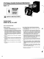
1
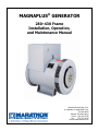
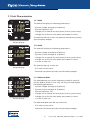
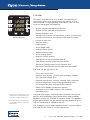
BELT COUPLED MOTOR – GENERATOR
SETS
GENERAL USER’S MANUAL
MOTOR – GENERATOR SETS
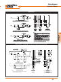
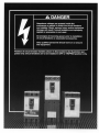
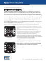
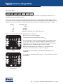
WARNING
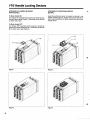
DO NOT LIFT THE UNIT WITH LIFTING EYE
BOLTS ON GENERATOR AND MOTOR. USE 2”
DIAMETER HOLES PROVIDED IN THE BASE
DANGER
HIGH VOLTAGE
CAUTION - CONNECT EQUIPMENT GROUND
TO GROUND STUD AND INSULATE LEAD
TERMINALS
BEFORE
STARTING
THE
GENERATOR. FAILURE TO COMPLY MAY
RESULT IN ELECTRICAL SHOCK AND
DAMAGE TO THE UNIT
TABLE OF CONTENTS
BELT COUPLED MOTOR-GENERATOR SETS GENERAL
INSTRUCTIONS
TENSIONING GUIDE FOR V-BELT DRIVES
BASIC TROUBLE SHOOTING FOR BELT COUPLED MOTOR
GENERATOR SETS
BASIC TROUBLE SHOOTING FOR V-BELTS AND DRIVES
MOTOR MANUAL
GENERATOR MANUAL
VOLTAGE REGULATOR MANUAL
OUTPUT CIRCUIT BREAKER MANUAL
OUTPUT METER PACKAGE MANUAL
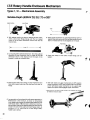
BELT COUPLED MOTOR-GENERATOR SETS
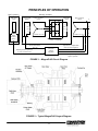
GENERAL INSTRUCTIONS
1.0
Georator Motor Generator (MG) Sets are inspected and fully tested at the factory
before shipping. Tests specifically conducted are:
1.1
Examination of both motor and generator for general operation, vibration
and noise.
1.2
Check of the output voltage of the generator, and the setting of voltage
regulator adjustments to the required output voltage.
1.3
Check of the output frequency of the generator at no load. If the frequency
is not within standard limits called for in the specifications, pulleys are
turned (machined) to provide the correct frequency output. The unit will
then be re-tested.
1.4
Motor starter operation is checked. Overload relay is tested.
1.5
Meters are checked for general operation, and calibrated if necessary.
1.6
Tripping function of the circuit breaker is checked using the test button.
2.0
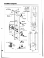
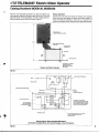
Users should follow national, local, and site codes for wiring, protection, and
installation. No holes are punched in either Motor Starter enclosure or Generator
connection box for electrical connections. The user should place these holes
where most convenient for the installation.
3.0
In selecting a location for the Motor-Generator Set, consideration should be given
to environment and ventilation. Do not obstruct air flow for air intake and
exhaust of the motor, generator, and pulleys & belts, or coupling. Allow a
distance of at least 3 feet around the perimeter of the unit. Restricted ventilation
will cause a motor-generator to operate at higher than desired temperature. Dirt,
dust, chemicals, snow, oil, grass, weeds, etc., all can clog passages of an open
frame motor. Georator uses open drip proof motors and generators, with drip
covers, as a standard. Open drip proof construction is intended for use indoors
where the atmosphere is relatively clean, dry and non-corrosive. According to the
NEMA MG-2 publication, a drip proof machine is “an open machine in which the
ventilating openings are so constructed that successful operation is not interfered
with when drops of liquid or solid particles strike or enter the enclosure at any
angle from 0 to 15 degrees, downward from the vertical”. Optional weather
protection enclosures may be provided for outdoor installation. See paragraph 12,
below, for a description of optional enclosures.
4.0
Ambient temperature of the air surrounding the MG Set should not exceed 40°C
(104°F), for standard rated motors and generators. De-rating may be necessary if
the ambient temperature exceeds 40°C. Consult Georator engineering for
recommendations. For estimated values of heat generated by the MG set under
full-load conditions (BTU/hr) please consult Georator engineering.
5.0
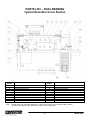
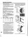
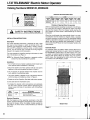
Eyebolts or lifting lugs on the motor or the generator are intended only for lifting
the motor or generator. These lifting provisions should never be used to handle
the entire MG Set. Please use the holes provided in the base for lifting the entire
assembly.
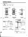
6.0
The MG Set base should be mounted on level, solid foundation. Georator
recommends using the 4 mounting holes in the base for mounting the base
directly on a rigid foundation. If these holes are used, 5/8” bolts will be required
for mounting. For mounting the unit on a concrete foundation , anchored bolts
can be used with a maximum nut torque of approx. 30 lb-ft. Anchored bolts can
pull loose if the concrete is overstressed by too much bolt tension. If grouting is
used, always check for cracks and gaps.
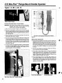
7.0
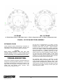
All rotating parts such as couplings, pulleys, and unused shaft extensions are
guarded in accordance with ANSIB15.1. Welded steel guards are provided on all
MG sets. Belt guard screens are welded in the front end of the belt guards for
ventilation and should not be obstructed.
8.0
Excessive Vibration may be the result of:
8.1
Un-even mounting surface.
8.2
Non rigid mounting surface, or loose mounting bolt(s).
8.3
For coupled-in-line units, coupling misalignment.
8.4
Belt tension and alignment (please refer to the belt tensioning and
maintenance section of the service manual).
8.5
Inherent vibration in either motor or generator, or both. This vibration
may occur as a result of worn bearings, or an unbalanced rotor.
8.6
For belted units, improper balance on the either, or both, sheaves.
9.0
Audible Noise: Belted motor-generator sets are typically louder than coupled-inline motor-generator sets. Indoor installation sites requires consideration for the
noise level that the set is likely to produce. As far as speech interference is
concerned, maximum levels recommended for offices are 60-65 dB. For belted
units, an estimate for Georator’s MG sets sound pressure level is dB 75-85 dB at 3
feet. This level may vary under given operating and environment conditions and
is expected to be maximum when the MG set is operating under full load
condition, and near a corner with poor sound absorbing reflective surfaces. It will
be even higher than the above levels with abnormal vibration conditions caused
by loose belts. A rigid sealed enclosure, with baffles, reduces noise levels
typically by 15-25 dB. Although typical sound attenuating enclosures offered by
Georator are not sealed at the bottom, careful design of the enclosure, baffles, and
inclusion of acoustical absorbing materials substantially reduce the audible noise
of the MG by typically 25-30 dB at 3 feet.
10.0
Electrical Considerations:
10.1 Apply the correct input voltage to the Motor Starter terminals. Motors
may operate within ±10% of their nameplate; however performance
characteristics will differ from nameplate data. Maximum frequency
variation may not exceed ±5% rated frequency. Good electrical systems
and operating practice limit the voltage at the motor under load to not
more than ±5% of nameplate. Also note that starting motors at lower
input voltages will reduce the starting torque, thereby prolonging the
acceleration time of the motor from stand still (locked rotor) to rated
speed. With MG Sets, the motor is already started under some load, which
is the generator’s inertia. For full voltage starting, the maximum
allowable time for small frame motors (up to 286T) is 10 seconds, for
medium frames (324T-326T) is 15 seconds, and for large frames (364T449T) is 15 seconds.
10.2 To prevent nuisance tripping when starting the unit, ensure that an
appropriately sized circuit breaker is used with the instantaneous trip set at
least at 800% of the Full Load Amp of the motor (per NEC Table 430152). Typical locked rotor current (for across the line start) can be as high
as 600% to 800% of full load motor amps (FLA). Georator offers reduced
voltage motor starters as a standard for units using 125 HP motors and
above. Part winding motor starters can reduce the starting current by 50%,
whereas Wye/Delta motor starters can reduce starting current down to
33% of the normal starting current. Solid-State Soft Starters can
significantly reduce the starting current of the motor to a controlled level
usually selected by the user in the range of 25% - 55% of the motor full
load current.
10.3 All motors used on Georator MG sets confirm with the EPACT mandate
requirements for high efficiency induction motors.
10.4 Check input voltage periodically. Voltage imbalances cause temperature
rise in the motor. A 3.5% voltage imbalance will typically cause 25%
temperature rise in the motor.
10.5 The Neutral wire on the Generator side is provided for most wiring
configurations for three phase Wye, and single phase Delta or Zig-Zag
connections. The Neutral wire – if provided – is not tied to the ground
potential in the factory. User to follow the installation requirements and
codes pertaining to grounding. Except in the case of MG Sets designed
for special testing requirements with complete isolation of Input and
Output, the structural steel base is electrically bonded to the motor and
generator frames through the mounting bolts of each, thus confirming to
NEC Article 250-104 (d). Other applicable standards for grounding are:
10.5.1 NEC, Article 430, Part L on grounding of motors.
10.5.2 NEC, Article 445-1 on grounding of generators.
10.5.3 NEC, Article 250 for general information on grounding.
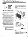
11.0
Optional Accessories: Several control and protection accessories are provided
with the MG sets. Below is a description of each. Other devices may also be
provided to facilitate special testing or operational requirements. Consult with
Georator Application Engineers.
11.1 Motor Starters: Starters used are generally Enclosed, Full Voltage,
Magnetic, Non-Reversing, with IEC Rated contacts. Non-combination
(without Input Circuit Breakers) starters are offered as a standard.
Enclosures are NEMA1 Type. Combination Motor Starters and different
type enclosures, e.g., dust tight, can also be provided. All starters are
supplied with motor overload Class 10 protection. This protection is a
solid state relay with wide selection of motor current and manual trip
reset. Door mounted Start/Stop push buttons are also provided.
Additional auxiliary contacts, and/or power control transformers can also
be made available for control purposes. Reduced voltage starters are the
general offering for large motors.
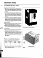
11.2 Circuit Breakers: Breakers are Thermal-Magnetic Trip, Molded Case, 2 or
3 pole Common Trip circuit breakers. A molded circuit breaker is one that
is assembled as an integral unit in a supportive and enclosing housing of
insulating material. The circuit breakers offered by Georator are provided
for the output (generator) and are wired to the generator terminals and
mounted on the generator connection box. They are supplied complete
with line and load terminals, and in the case of FD Frames (250 Amp
frames) and above the Breaker is UL listed for reverse feed applications.
For FD Frames and up, an adjustable magnetic trip unit is provided. In
addition to providing short circuit protection (through the magnetic trip
unit), and an overload protection (through the thermal trip unit), the circuit
breakers are often used, as convenient switches, to apply the “Load” to the
Generator terminals. Several accessories and modifications may
optionally be provided with the circuit breakers such as Shunt trip devices,
under-voltage release, and auxiliary switches. For “Safety and Installation
Instructions”, the user should consult the appropriate section of the service
manual. For general information on application and performance refer to
NEMA Standards Publications AB 1 and AB 3. For Guidelines for
Inspection and preventive maintenance consult NEMA AB 4.
11.3 Power Monitor: The power monitor is a solid-state digital triple display
multi-function power monitoring system. The power monitor
simultaneously displays every metered electrical power function
including:
11.3.1
11.3.2
11.3.3
11.3.4
Volts,
Amps,
Frequency,
KW or KVA
The Meter is featured with a large bright digital display and a smart
keypad for programming and calibration. The meter can also be supplied
with digital communications interface port such as RS232 or RS485 that
allows it to interface with other equipment and allow remote monitoring of
the MG operation. Full details on the power monitors features and
functions, calibration, and service can be found in the service manual.
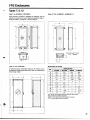
12.0
Optional Enclosures: These notes pertain to weather as well as sound attenuating
enclosures.
12.1 The enclosure is constructed in aluminum, and is provided with:
12.1.1 Access Door for belts (or couplings) service
12.1.2 Circulating fan
12.1.3 Thermostat switch
12.1.4 Access for circuit breaker, voltage adjustment, power monitoring,
and input and output wiring.
12.2 Access for input and output wiring is normally provided through input and
output connection boxes to which electrical connections are made by the
user. Connections from the motor (or motor starter) to the input box, and
from the generator (or output circuit breaker) to the output box are made
by Georator.
12.3 The enclosures are either mounted (bolted) on the MG steel base, or are
“drop over” type. The latter will be supplied as a separate item and final
electrical connection for the fan and thermostat switch is carried out by the
user.
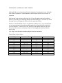
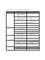
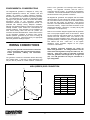
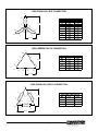
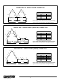
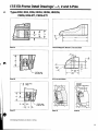
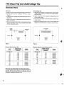
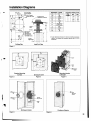
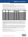
TENSIONING GUIDE FOR V-BELT DRIVES
Although belts are tensioned properly before shipment, loosening may occur during the
first weeks of operation. Tension should be checked after the first 24 to 40 hours of
operation.
Ideal tension is the tension at which the belt will not slip under peak load conditions.
However, note that over tensioning shortens belt and bearing life. Avoid the use of belt
dressing as this will damage the belts and lead to premature failure.
While an “educated thumb” may be acceptable for ordinary drives, we recommend the
use of a tension gauge which measures the pounds force required to deflect the belt a
specified distance. Vendors such as TB Woods provided detailed data on upper and
lower limits for tension as a function of belt size and length and should be used for
precise data.
(see: http://www.tbwoods.com/index.php for their free downloads).
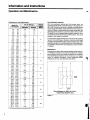
General data is shown below:
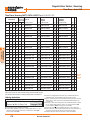
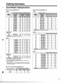
Belt Type
Smaller Sheave Dia.
Used Belt, lbs. force
New Belt, lbs force
BX
BX
CX
CX
D
3VX
5VX
5VX
5VX
8V
4.4 – 5.6
5.8 – 8.6
7.0 – 9.0
9.5 – 16.0
12.0 – 16.0
4.02 – 6.9
4.4 – 6.7
7.1 – 10.9
11.8 – 16.0
12.5 – 17.0
7.1
7.3
14.7
15.9
21.2
5.3
8.8
14.8
17.1
26.8
10.5
10.9
21.8
23.5
31.3
7.9
13.2
22.1
25.5
39.9
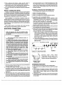
BASIC TROUBLE SHOOTING FOR BELT COUPLED MOTOR GENERATOR SETS
1. Check output voltage and output frequency.
A. Output voltage is adjustable using voltage adjusting pot and screw driver voltage
adjustment for voltage regulator. If there is no voltage adjustment, it is likely
that the voltage regulator has failed.
To check voltage regulator, remove leads F+ and F- from the voltage regulator
and noting polarity, put a 12 V DC battery, battery charger or DC power supply
across F+ and F- leads. Then turn the MG on and the output voltage at no load
should be high and stable. If so, the voltage regulator is the only thing that
doesn’t work. Replace the regulator.
If this is not the case, then a major generator problem exists that will need
factory repair.
2. The output frequency should be within plus or minus 1 percent.
A. If the no load output frequency is above 1%, check the input frequency—where
the output frequency will vary proportionally to the input frequency.
B. If the loaded output frequency is low (below 1%), check input frequency for
proportional relationship. If the input frequency is OK and the input voltage is OK,
check for belt tensioning.
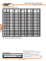
BASIC TROUBLE SHOOTING FOR V-BELTS AND DRIVES
Problem
Short Belt Life
Probable Cause
•
Belts Squeal
Belt Breakage
Excess Vibration
•
Tension belts
•
Eliminate obstruction or
realign drive to provide
clearance
•
•
•
•
•
Use high-temperature belts
Provide ventilation
Shield belts
Check for leaky bearings
Clean belts and sheaves
•
Spin burns from belt slipping
on drive sheave under a
stalled load condition or when
starting
Gouges or extreme cover
wear caused by belts rubbing
on drive guards or other
objects
High ambient temperature
•
Grease or oil on belts
•
Worn sheaves
•
Replace sheaves
•
•
•
Damaged cord section in belts
Frayed or gouged belts
Excessive vibration
•
Replace belts
•
Worn sheaves
•
•
•
Tension belts
Replace belts if damaged
Replace sheaves
•
Sheave misalignment
•
Realign sheaves
•
•
•
•
High starting load
Belts not tensioned properly
Excessive overload
Insufficient arc of contact
•
•
Tension drive
Redesign & replace drive
•
Revise centerline distance
•
Foreign material in drive
•
•
•
•
Belts
damaged
during
installation
Shock or extreme overload
•
•
Provide drive guard
(standard on Georator units)
Follow installation
instructions
Eliminate overload
Redesign drive
•
•
•
Damaged belt cord section
Loose belts
Belts improperly tensioned
•
•
•
Replace belts
Tension drive
Tension belts evenly
•
Belts turn over in
grooves
Trouble-Shoot
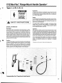
Sprecher + Schuh magnetic motor
starters are intended to eliminate the
purchase and assembly of a separate
contactor, overload relay and associated
wiring. When purchased with an
enclosure, the starters are mounted and
ready to install on receipt.
Open and
Enclosed
Magnetic
Motor Starters
Starting with the best
Built to your
specifications and
ready to install
At the heart of all magnetic starters is the
Sprecher + Schuh CAT7, CAT6 and
CAT5 line of motor starters. These
starters are compact and offer intermediate sizes to better match specific motor
requirements. This equates to generous
wiring space and less wasted horsepower
capacity.
Top line protection…
Larger starters are equipped with
Sprecher + Schuh’s sophisticated CEF1
Electronic Motor Protector, which also
utilizes solid state technology to provide
an extremely accurate thermal image of
the motor. The CEF1 includes many
standard features including digital slide
switches, LED diagnostics and single
phase / phase unbalance protection.
Type 1
Type 3R
The right enclosure…
whatever the application
Sprecher + Schuh’s broad line of IEC
style starters can be purchased preinstalled in a variety of standard
enclosures. Cataloged enclosures
include:
Type 4
Type 4X
General Purpose
Industrial Dusttight
Industrial Dusttight (outdoor)
Watertight
Watertight, Corrosion Resistant
Even though these are the most popular
enclosure types for most industrial applications, we can house any starter in a custom
enclosure of your choosing.
Quality enclosures ensure
the highest confidence
Sprecher + Schuh only sources enclosures from name brand manufacturers,
ensuring the highest quality. We
primarily use enclosures that meet UL
Standards, i.e., Type 1, Type 3R, etc.,
however, we can also source IEC-type
enclosures at your request. Enclosures
are sized first to accommodate the depth
of the contactor and offer sufficient
electrical clearances to satisfy UL.
Add a variety of modifications
If you need a larger enclosure than what
is specified in our catalog, your sales
representative and our Engineering
department will work with you to
customize any of our enclosed products
to suit your exact specifications. Any
combination of enclosure types, sizes,
pilot devices, meters and other modifications can be combined to provide
exactly the panel you need.
C19
C
Starters &
Enclosed Prod.
R
Magnetic starters (up to 180A) are
equipped with Sprecher + Schuh’s new
CEP7 solid state overload relay. Unlike
traditional overload relays that indirectly
sense motor current through heater
elements, CEP7 solid state overload
relays measure motor current directly
through integrated current transformers
and on board electronics. The electronics provide numerous advantages over
electromechanical relays.
M1
M12
M3
M4
F4
MAG
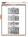
Magnetic Motor Starters / Non-Reversing
Three Phase - Series CAT
Three Phase, Non-Reversing CAT7, CAT6 & CAT5 (Open, M1 & M12 / M3)
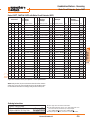
Maximum Horsepower Auxiliary Open
Three Phase
Contacts per Type ➏
Contactor ➌
200V 230V 460V 575V NO
Starters &
Enclosed Prod.
C
D M12 (M3 ➋)
I Industrial
M Dusttight
M1
General
Purpose
NC Catalog Number
Price Catalog Number
Price ➊ Catalog Number
D
I
M
Price ➊
2
2
5
7 1/2
1
0
CAT7-9-✱-◆
140
CAT7-9-✱-◆-G0
180
A
CAT7-9-✱-◆-D0
255
L
3
3
7 1/2
10
1
0
CAT7-12-✱-◆
160
CAT7-12-✱-◆-G0
200
A
CAT7-12-✱-◆-D0
275
L
5
5
10
15
1
0
CAT7-16-✱-◆
175
CAT7-16-✱-◆-G0
215
A
CAT7-16-✱-◆-D0
290
L
5
7 1/2
15
15
1
0
CAT7-23-✱-◆
185
CAT7-23-✱-◆-G0
225
A
CAT7-23-✱-◆-D0
300
L
7 1/2
10
20
25
1
0
CAT7-30-✱-◆
245
CAT7-30-✱-◆-G0
275
A
CAT7-30-✱-◆-D0
360
L
10
10
25
30
1
0
CAT7-37-✱-◆
275
CAT7-37-✱-◆-G0
300
A
CAT7-37-✱-◆-D0
385
L
10
15
30
30
1
0
CAT7-43-✱-◆
315
CAT7-43-✱-◆-G0
440
B
CAT7-43-✱-◆-D0
470
M
15
20
40
50
1
0
CAT7-60-✱-◆
375
CAT7-60-✱-◆-G0
470
B
CAT7-60-✱-◆-D0
575
O
20
25
50
60
1
0
CAT7-72-✱-◆
410
CAT7-72-✱-◆-G0
500
B
CAT7-72-✱-◆-D0
610
O
25
30
60
60
1
0
CAT7-85-✱-◆
445
CAT7-85-✱-◆-G0
540
B
CAT7-85-✱-◆-D0
645
O
25
30
60
75
1
1
CAT6-95-✱-◆ ➍
775
CAT6-95-✱-◆-G0 ➍
1150
E
CAT6-95-✱-◆-D0 ➍
1300
Q
40
40
75
100
1
1
CAT6-110-✱-◆ ➍
900
CAT6-110-✱-◆-G0 ➍
1250
E
CAT6-110-✱-◆-D0 ➍
1475
R
40
50
100
125
1
1
CAT6-140-✱-◆ ➍
1225 CAT6-140-✱-◆-G0 ➍
1700
F
CAT6-140-✱-◆-D0 ➍
1975
T
50
60
150
150
1
1
CAT6-180-✱-◆ ➍
1500 CAT6-180-✱-◆-G0 ➍
1975
F
CAT6-180-✱-◆-D0 ➍
2250
T
60
75
150
200
1
1
CAT6-210-EI-✱-◆
2200 CAT6-210-EI-✱-◆-G0
2650
F
CAT6-210-EI-✱-◆-D0
2915
T
75
100
200
250
1
1
CAT6-250-EI-✱-◆
2350 CAT6-250-EI-✱-◆-G0
3300
I
CAT6-250-EI-✱-◆-D0
3400
I
100
125
250
300
1
1
CAT6-300-EI-✱-◆
2500 CAT6-300-EI-✱-◆-G0
3600
I
CAT6-300-EI-✱-◆-D0
3700
I
150
150
350
400
1
1
CAT6-420-EI-✱-◆
4100 CAT6-420-EI-✱-◆-G0
5200
I
CAT6-420-EI-✱-◆-D0
5300
I
200
250
500 600➐
1
1
CAT6-630-EI-✱-◆
R/F
CAT6-630-EI-✱-◆-G0
R/F
~
CAT6-630-EI-✱-◆-D0
R/F
~
250
300
600 700➐
1
1
CAT6-860-EI-✱-◆
R/F
CAT6-860-EI-✱-◆-G0
R/F
~
CAT6-860-EI-✱-◆-D0
R/F
~
200
250
500
500
2
2
CAT5-700-✱-◆
R/F
CAT5-700-✱-◆-G0
R/F
~
CAT5-700-✱-◆-D0
R/F
~
250
300
600
600
2
2
CAT5-860-✱-◆
R/F
CAT5-860-✱-◆-G0
R/F
~
CAT5-860-✱-◆-D0
R/F
~
350
400
800
900
1
2
CAT5-1000-✱-◆ ➎
R/F
CAT5-1000-✱-◆-G0 ➎
R/F
~
CAT5-1000-✱-◆-D0 ➎
R/F
~
450
450
900
900
1
2
CAT5-1200-✱-◆
R/F
CAT5-1200-✱-◆-G0
R/F
~
CAT5-1200-✱-◆-D0
R/F
~
MAG
NOTE: Catalog numbers, list prices and enclosure dimensions reflect contactors
with AC coils. For DC coils, select Coil Code from the DC Coil Code table on page
C53 and follow the instructions for modifying catalog numbers and list prices.
Ordering Instructions
Specify Catalog Number
● Replace (✱) With Coil Code
● Replace (◆) With O/L Relay Code
●
C20
See page C53
See pages C54-56
➊ Refer to page C79-80 for dimensional information.
➋ For M3 outdoor applications, replace "D" in catalog number with an "R". Price
remains the same, dimensions may change. Example: CAT7-23-✱-◆-D0
becomes CAT7-23-✱-◆-R0.
➌ Contactors are equipped with number and type of auxiliaries indicated. See
Modification Section to order additional or different auxiliary contacts.
➍ CAT6-95…CAT6-180 starters are available with electronic interface coil “EI.”
Change catalog number to include “-EI”. Example: CAT6-95-✱-◆ becomes
CAT6-95-EI-✱-◆. See page C53 for price adder.
➎ CAT5-1000 HP ratings per IEC utilization category AC-3, not UL Approved.
➏ CAT5 “Open Type” starters include terminal screws only. If lugs are required, see
“Accessories” for CA6 and CA5 contactors in Section A of this catalog.
➐ Pending UL Approval. Contact your Sprecher + Schuh representative.
Discount Schedule A-1
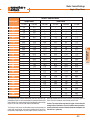
Magnetic Motor Starters / Non-Reversing
Three Phase - Series CAT
Three Phase, Non-Reversing CAT7, CAT6 & CAT5 (M4 & F4)
Maximum Horsepower Auxiliary M4
Three Phase
Contacts per Watertight
Contactor ➋
200V 230V 460V 575V NO
D F4
I Watertight
M Corrosion Resistant
NC
Catalog Number
Price ➊ Catalog Number
D
I
M
Price ➊
2
5
7 1/2
1
0
CAT7-9-✱-◆-W0
340
N
CAT7-9-✱-◆-C0
270
S1
3
3
7 1/2
10
1
0
CAT7-12-✱-◆-W0
360
N
CAT7-12-✱-◆-C0
290
S1
5
5
10
15
1
0
CAT7-16-✱-◆-W0
375
N
CAT7-16-✱-◆-C0
305
S1
5
7 1/2
15
15
1
0
CAT7-23-✱-◆-W0
385
N
CAT7-23-✱-◆-C0
315
S1
7 1/2
10
20
25
1
0
CAT7-30-✱-◆-W0
445
N
CAT7-30-✱-◆-C0
435
U1
10
10
25
30
1
0
CAT7-37-✱-◆-W0
475
N
CAT7-37-✱-◆-C0
465
U1
10
15
30
30
1
0
CAT7-43-✱-◆-W0
515
N
CAT7-43-✱-◆-C0
500
U1
15
20
40
50
1
0
CAT7-60-✱-◆-W0
625
O
CAT7-60-✱-◆-C0
565
U1
20
25
50
60
1
0
CAT7-72-✱-◆-W0
660
O
CAT7-72-✱-◆-C0
600
U1
25
30
60
60
1
0
CAT7-85-✱-◆-W0
700
O
CAT7-85-✱-◆-C0
640
U1
25
30
60
75
1
1
CAT6-95-✱-◆-W0 ➌
1500
Q
CAT6-95-✱-◆-C0 ➌
1400 W2
40
40
75
100
1
1
CAT6-110-✱-◆-W0 ➌
1700
R
CAT6-110-✱-◆-C0 ➌
1600 W2
40
50
100
125
1
1
CAT6-140-✱-◆-W0 ➌
2150
T
CAT6-140-✱-◆-C0 ➌
2600 X1
50
60
150
150
1
1
CAT6-180-✱-◆-W0 ➌
2425
T
CAT6-180-✱-◆-C0 ➌
2900 X1
60
75
150
200
1
1
CAT6-210-EI-✱-◆-W0
3100
T
CAT6-210-EI-✱-◆-C0
3600 X1
75
100
200
250
1
1
CAT6-250-EI-✱-◆-W0
3925
J
CAT6-250-EI-✱-◆-C0
3800 X1
100
125
250
300
1
1
CAT6-300-EI-✱-◆-W0
4100
J
CAT6-300-EI-✱-◆-C0
4250 Y1
150
150
350
400
1
1
CAT6-420-EI-✱-◆-W0
5700
J
CAT6-420-EI-✱-◆-C0
5850 Y1
200
250
500 600➎
1
1
CAT6-630-EI-✱-W0
R/F
~
CAT6-630-EI-✱-C0
8525
~
250
300
600 700➎
1
1
CAT6-860-EI-✱-W0
R/F
~
CAT6-860-EI-✱-C0
R/F
~
200
250
500
500
2
2
CAT5-700-✱-◆-W0
R/F
~
CAT5-700-✱-◆-C0
R/F
~
250
300
600
600
2
2
CAT5-860-✱-◆-W0
R/F
~
CAT5-860-✱-◆-C0
R/F
~
350
400
800
900
1
2
CAT5-1000-✱-◆-W0 ➍
R/F
~
CAT5-1000-✱-◆-C0 ➍
R/F
~
450
450
900
900
1
2
CAT5-1200-✱-◆-W0
R/F
~
CAT5-1200-✱-◆-C0
R/F
~
C
Starters &
Enclosed Prod.
2
MAG
NOTE: Catalog numbers, list prices and enclosure dimensions reflect contactors
with AC coils. For DC coils, select Coil Code from the DC Coil Code table on page
C53 and follow the instructions for modifying catalog numbers and list prices.
Ordering Instructions
Specify Catalog Number
● Replace (✱) With Coil Code
● Replace (◆) With O/L Relay Code
●
See page C53
See pages C54-56
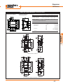
➊ Refer to page C79-80 for dimensional information.
➋ Contactors are equipped with number and type of auxiliaries indicated. See
Modification Section to order additional or different auxiliary contacts.
➌ CAT6-95…CAT6-180 starters are available with electronic interface coil “EI.”
Change catalog number to include “-EI”. Example: CAT6-95-✱-◆-W0 becomes
CAT6-95-EI-✱-◆-W0. See page C53 for price adder.
➍ CAT5-1000 HP ratings per IEC utilization category AC-3, not UL Approved.
➎ Pending UL Approval. Contact your Sprecher + Schuh representative.
Discount Schedule A-1
C21
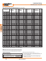
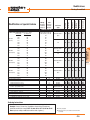
Magnetic Motor Starters / Reversing
Three Phase - Series CAUT
Three Phase, Reversing CAUT7, CAUT6 & CAUT5 (Open, M1 & M12 / M3)
Maximum Horsepower Auxiliary Open
Three Phase
Contacts per Type ➐
Contactor ➌
200V 230V 460V 575V NO NC ➍ Catalog Number
Starters &
Enclosed Prod.
C
D M12 (M3 ➋)
I Industrial
M Dusttight
M1
General
Purpose
Price Catalog Number
Price ➊ Catalog Number
D
I
M
Price ➊
2
2
5
7 1/2
1
1
CAUT7-9-✱-◆
255
CAUT7-9-✱-◆-G0
400
B
CAUT7-9-✱-◆-D0
430
M
3
3
7 1/2
10
1
1
CAUT7-12-✱-◆
295
CAUT7-12-✱-◆-G0
440
B
CAUT7-12-✱-◆-D0
470
M
5
5
10
15
1
1
CAUT7-16-✱-◆
320
CAUT7-16-✱-◆-G0
465
B
CAUT7-16-✱-◆-D0
495
M
5
7 1/2
15
15
1
1
CAUT7-23-✱-◆
345
CAUT7-23-✱-◆-G0
490
B
CAUT7-23-✱-◆-D0
520
M
7 1/2
10
20
25
1
1
CAUT7-30-✱-◆
425
CAUT7-30-✱-◆-G0
570
B
CAUT7-30-✱-◆-D0
600
M
10
10
25
30
1
1
CAUT7-37-✱-◆
480
CAUT7-37-✱-◆-G0
620
B
CAUT7-37-✱-◆-D0
650
M
10
15
30
30
1
1
CAUT7-43-✱-◆
570
CAUT7-43-✱-◆-G0
725
B
CAUT7-43-✱-◆-D0
750
M
15
20
40
50
1
1
CAUT7-60-✱-◆
690
CAUT7-60-✱-◆-G0
925
C
CAUT7-60-✱-◆-D0
950
O
20
25
50
60
1
1
CAUT7-72-✱-◆
760
CAUT7-72-✱-◆-G0
995
C
CAUT7-72-✱-◆-D0
1020
O
25
30
60
60
1
1
CAUT7-85-✱-◆
825
CAUT7-85-✱-◆-G0
1060
C
CAUT7-85-✱-◆-D0
1085
O
25
30
60
75
1
1
CAUT6-95-✱-◆ ➎
1525 CAUT6-95-✱-◆-G0 ➎
1900
E
CAUT6-95-✱-◆-D0 ➎
2050
R
40
40
75
100
1
1
CAUT6-110-✱-◆ ➎
1625 CAUT6-110-✱-◆-G0 ➎
2000
E
CAUT6-110-✱-◆-D0 ➎
2150
R
40
50
100
125
1
1
CAUT6-140-✱-◆ ➎
2275 CAUT6-140-✱-◆-G0 ➎
2750
F
CAUT6-140-✱-◆-D0 ➎
3000
T
50
60
150
150
1
1
CAUT6-180-✱-◆ ➎
2850 CAUT6-180-✱-◆-G0 ➎
3350
F
CAUT6-180-✱-◆-D0 ➎
3600
T
60
75
150
200
1
1
CAUT6-210-EI-✱-◆
3975 CAUT6-210-EI-✱-◆-G0
4400
F
CAUT6-210-EI-✱-◆-D0
4650
T
75
100
200
250
1
1
CAUT6-250-EI-✱-◆
4300 CAUT6-250-EI-✱-◆-G0
5300
I
CAUT6-250-EI-✱-◆-D0
5400
I
100
125
250
300
1
1
CAUT6-300-EI-✱-◆
4525 CAUT6-300-EI-✱-◆-G0
5500
I
CAUT6-300-EI-✱-◆-D0
5600
I
115
135
275
350
1
1
CAUT6-420-EI-✱-◆
8000 CAUT6-420-EI-✱-◆-G0
9000
I
CAUT6-420-EI-✱-◆-D0
9100
I
200
250
500 600➑
1
1
CAUT6-630-EI-✱-◆
R/F
CAUT6-630-EI-✱-◆-G0
R/F
~
CAUT6-630-EI-✱-◆-D0
R/F
~
250
300
600 700➑
1
1
CAUT6-860-EI-✱-◆
R/F
CAUT6-860-EI-✱-◆-G0
R/F
~
CAUT6-860-EI-✱-◆-D0
R/F
~
200
250
500
500
2
1
CAUT5-700-✱-◆
R/F
CAUT5-700-✱-◆-G0
R/F
~
CAUT5-700-✱-◆-D0
R/F
~
250
300
600
600
2
1
CAUT5-860-✱-◆
R/F
CAUT5-860-✱-◆-G0
R/F
~
CAUT5-860-✱-◆-D0
R/F
~
350
400
800
900
1
1
CAUT5-1000-✱-◆ ➏
R/F
CAUT5-1000-✱-◆-G0 ➏
R/F
~
CAUT5-1000-✱-◆-D0 ➏
R/F
~
450
450
900
900
1
1
CAUT5-1200-✱-◆
R/F
CAUT5-1200-✱-◆-G0
R/F
~
CAUT5-1200-✱-◆-D0
R/F
~
MAG
NOTE: Catalog numbers, list prices and enclosure dimensions reflect contactors
with AC coils. For DC coils, select Coil Code from the DC Coil Code table on page
C53 and follow the instructions for modifying catalog numbers and list prices.
Ordering Instructions
Specify Catalog Number
● Replace (✱) With Coil Code
● Replace (◆) With O/L Relay Code
●
See page C53
See pages C54-56
➊ Refer to page C79-80 for dimensional information.
➋ For M3 outdoor applications, replace "D" in catalog number with an "R". Price
remains the same, dimensions may change. Example: CAUT7-23-✱-◆-D0
becomes CAUT7-23-✱-◆-R0.
C22
➌ Contactors are equipped with number and type of auxiliaries indicated. See
Modification Section to order additional or different auxiliary contacts.
➍ One N.C. auxiliary contact is used for electrical interlocking. On CAUT7 reversing
starters, the N.C. contact comes from the Mechanical/Electrical Interlock unit
(Cat # CM7-02).
➎ CAUT6-95…CAUT6-180 reversing starters are available with electronic interface
coil “EI.” Change catalog number to include “-EI”. Example: CAUT6-95-✱-◆
becomes CAUT6-95-EI-✱-◆. See page C53 for price adder.
➏ CAUT5-1000 HP ratings per IEC utilization category AC-3, not UL Approved.
➐ CAUT5 “Open Type” starters include terminal screws only. If lugs are required, see
“Accessories” for CA6 and CA5 contactors in Section A of this catalog.
➑ Pending UL Approval. Contact your Sprecher + Schuh representative.
Discount Schedule A-1
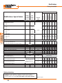
Magnetic Motor Starters / Reversing
Three Phase - Series CAUT
Three Phase, Reversing CAUT7, CAUT6 & CAUT5 (M4 & F4)
Maximum Horsepower Auxiliary M4
Three Phase
Contacts per Watertight
Contactor ➋
D F4
I Watertight
M Corrosion Resistant
200V 230V 460V 575V NO NC ➌ Catalog Number
Price ➊ Catalog Number
D
I
M
Price ➊
2
5
7.5
1
1
CAUT7-9-✱-◆-W0
460
N
CAUT7-9-✱-◆-C0
450
U1
3
3
7.5
10
1
1
CAUT7-12-✱-◆-W0
500
N
CAUT7-12-✱-◆-C0
490
U1
5
5
10
15
1
1
CAUT7-16-✱-◆-W0
530
N
CAUT7-16-✱-◆-C0
520
U1
5
7.5
15
15
1
1
CAUT7-23-✱-◆-W0
555
N
CAUT7-23-✱-◆-C0
545
U1
7.5
10
20
25
1
1
CAUT7-30-✱-◆-W0
630
N
CAUT7-30-✱-◆-C0
620
U1
10
10
25
30
1
1
CAUT7-37-✱-◆-W0
680
N
CAUT7-37-✱-◆-C0
675
U1
10
15
30
30
1
1
CAUT7-43-✱-◆-W0
755
N
CAUT7-43-✱-◆-C0
750
U1
15
20
40
50
1
1
CAUT7-60-✱-◆-W0
930
O
CAUT7-60-✱-◆-C0
1030 V1
20
25
50
60
1
1
CAUT7-72-✱-◆-W0
1000
O
CAUT7-72-✱-◆-C0
1100 V1
25
30
60
60
1
1
CAUT7-85-✱-◆-W0
1075
O
CAUT7-85-✱-◆-C0
1175 V1
25
30
60
75
1
1
CAUT6-95-✱-◆-W0 ➍
2250
R
CAUT6-95-✱-◆-C0 ➍
2150 W2
40
40
75
100
1
1
CAUT6-110-✱-◆-W0 ➍ 2360
R
CAUT6-110-✱-◆-C0 ➍ 2300 W2
40
50
100
125
1
1
CAUT6-140-✱-◆-W0 ➍ 3250
T
CAUT6-140-✱-◆-C0 ➍ 3825 X1
50
60
150
150
1
1
CAUT6-180-✱-◆-W0 ➍ 3800
T
CAUT6-180-✱-◆-C0 ➍ 4400 X1
60
75
150
200
1
1
CAUT6-210-EI-✱-◆-W0
4900
T
CAUT6-210-EI-✱-◆-C0
5500 X1
75
100
200
250
1
1
CAUT6-250-EI-✱-◆-W0
6000
J
CAUT6-250-EI-✱-◆-C0
6250 Y1
100
125
250
300
1
1
CAUT6-300-EI-✱-◆-W0
6200
J
CAUT6-300-EI-✱-◆-C0
6500 Y1
115
135
275
350
1
1
CAUT6-420-EI-✱-◆-W0
9600
J
CAUT6-420-EI-✱-◆-C0
10000 Y1
200
250
500 600➏
1
1
CAUT6-630-EI-✱-W0
R/F
~
CAUT6-630-EI-✱-C0
R/F
~
250
300
600 700➏
1
1
CAUT6-860-EI-✱-W0
R/F
~
CAUT6-860-EI-✱-C0
R/F
~
200
250
500
500
2
1
CAUT5-700-✱-◆-W0
R/F
~
CAUT5-700-✱-◆-C0
R/F
~
250
300
600
600
2
1
CAUT5-860-✱-◆-W0
R/F
~
CAUT5-860-✱-◆-C0
R/F
~
350
400
800
900
1
1
CAUT5-1000-✱-◆-W0 ➎
R/F
~
CAUT5-1000-✱-◆-C0 ➎
R/F
~
450
450
900
900
1
1
CAUT5-1200-✱-◆-W0
R/F
~
CAUT5-1200-✱-◆-C0
R/F
~
C
Starters &
Enclosed Prod.
2
MAG
NOTE: Catalog numbers, list prices and enclosure dimensions reflect contactors
with AC coils. For DC coils, select Coil Code from the DC Coil Code table on page
C53 and follow the instructions for modifying catalog numbers and list prices.
Ordering Instructions
Specify Catalog Number
● Replace (✱) With Coil Code
● Replace (◆) With O/L Relay Code
●
See page C53
See pages C54-56
➊ Refer to page C79-80 for dimensional information.
➋ Contactors are equipped with number and type of auxiliaries indicated. See
Modification Section to order additional or different auxiliary contacts.
➌ One N.C. auxiliary contact is used for electrical interlocking. On CAUT7 reversing
starters, the N.C. contact comes from the Mechanical/Electrical Interlock unit
(Cat # CM7-02).
➍ CAUT6-95…CAUT6-180 reversing starters available with electronic interface coil
“EI.” Change catalog number to include “-EI”. Example: CAUT6-95-✱-◆-W0
becomes CAUT6-95-EI-✱-◆-W0. See page C53 for price adder.
➎ CAUT5-1000 HP ratings per IEC utilization category AC-3, not UL Approved.
➏ Pending UL Approval. Contact your Sprecher + Schuh representative.
Discount Schedule A-1
C23
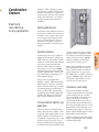
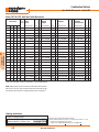
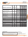
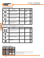
Magnetic Motor Starters / Non-Reversing
Single Phase - Series CBT
Single Phase, Non-Reversing CBT7 & CBT6
Maximum Auxiliary Open
Horsepower Contacts per Type
Single Ø Contactor ➌
115V 230V NO
Starters &
Enclosed Prod.
C
MAG
D M12 (M3 ➋)
I Industrial
M Dusttight
M1
General
Purpose
D M4
I Watertight
M
D F4
I Watertight
M Corr. Resis.
D
I
M
NC Catalog No. Price Catalog No. Price ➊ Catalog No. Price ➊ Catalog No. Price ➊ Catalog No. Price ➊
1/3
1
1
0
1/2
2
1
0
1
3
1
0
2
3
1
0
2
5
1
0
3
5
1
0
3
7 1/2
1
0
5
10
1
0
5
15
1
0
7 1/2
15
1
0
7 1/2
15
1
1
10
25
1
1
15
30
1
1
~
40
1
1
~
50
1
1
CBT7-9
140 CBT7-9
-✱-◆
-✱-◆-G0
CBT7-12
160 CBT7-12
-✱-◆
-✱-◆-G0
CBT7-16
175 CBT7-16
-✱-◆
-✱-◆-G0
CBT7-23
185 CBT7-23
-✱-◆
-✱-◆-G0
CBT7-30
245 CBT7-30
-✱-◆
-✱-◆-G0
CBT7-37
275 CBT7-37
-✱-◆
-✱-◆-G0
CBT7-43
315 CBT7-43
-✱-◆
-✱-◆-G0
CBT7-60
375 CBT7-60
-✱-◆
-✱-◆-G0
CBT7-72
410 CBT7-72
-✱-◆
-✱-◆-G0
CBT7-85
445 CBT7-85
-✱-◆
-✱-◆-G0
CBT6-95
775 CBT6-95
-✱-◆ ➍
-✱-◆-G0 ➍
CBT6-110
900 CBT6-110
-✱-◆ ➍
-✱-◆-G0 ➍
CBT6-140
1225 CBT6-140
-✱-◆ ➍
-✱-◆-G0 ➍
CBT6-180
1500 CBT6-180
-✱-◆ ➍
-✱-◆-G0 ➍
CBT6-210-EI 2200 CBT6-210-EI
-✱-◆
-✱-◆-G0
180
A
200
A
215
A
225
A
275
A
300
A
440
B
470
B
500
B
540
B
1150
E
1250
E
1700
F
1975
F
2650
F
CBT7-9
-✱-◆-D0
CBT7-12
-✱-◆-D0
CBT7-16
-✱-◆-D0
CBT7-23
-✱-◆-D0
CBT7-30
-✱-◆-D0
CBT7-37
-✱-◆-D0
CBT7-43
-✱-◆-D0
CBT7-60
-✱-◆-D0
CBT7-72
-✱-◆-D0
CBT7-85
-✱-◆-D0
CBT6-95
-✱-◆-D0 ➍
CBT6-110
-✱-◆-D0 ➍
CBT6-140
-✱-◆-D0 ➍
CBT6-180
-✱-◆-D0 ➍
CBT6-210-EI
-✱-◆-D0
255
L
275
L
290
L
300
L
360
L
385
L
470
M
575
O
610
O
645
O
1300
Q
1475
R
1975
T
2250
T
2915
T
CBT7-9
-✱-◆-W0
CBT7-12
-✱-◆-W0
CBT7-16
-✱-◆-W0
CBT7-23
-✱-◆-W0
CBT7-30
-✱-◆-W0
CBT7-37
-✱-◆-W0
CBT7-43
-✱-◆-W0
CBT7-60
-✱-◆-W0
CBT7-72
-✱-◆-W0
CBT7-85
-✱-◆-W0
CBT6-95
-✱-◆-W0 ➍
CBT6-110
-✱-◆-W0 ➍
CBT6-140
-✱-◆-W0 ➍
CBT6-180
-✱-◆-W0 ➍
CBT6-210-EI
-✱-◆-W0
340
360
375
385
445
475
515
625
660
700
1500
1700
2150
2425
3100
N CBT7-9
-✱-◆-C0
N CBT7-12
-✱-◆-C0
N CBT7-16
-✱-◆-C0
N CBT7-23
-✱-◆-C0
N CBT7-30
-✱-◆-C0
N CBT7-37
-✱-◆-C0
N CBT7-43
-✱-◆-C0
O CBT7-60
-✱-◆-C0
O CBT7-72
-✱-◆-C0
O CBT7-85
-✱-◆-C0
Q CBT6-95
-✱-◆-C0 ➍
R CBT6-110
-✱-◆-C0 ➍
T CBT6-140
-✱-◆-C0 ➍
T CBT6-180
-✱-◆-C0 ➍
T CBT6-210-EI
-✱-◆-C0
270
S1
290
S1
305
S1
315
S1
435
U1
465
U1
500
U1
565
U1
600
U1
640
U1
1400 W2
1600 W2
2600 X1
2900 X1
3600 X1
NOTE: Catalog numbers, list prices and enclosure dimensions reflect contactors
with AC coils. For DC coils, select Coil Code from the DC Coil Code table on page
C53 and follow the instructions for modifying catalog numbers and list prices.
Ordering Instructions
Specify Catalog Number
● Replace (✱) With Coil Code
● Replace (◆) With O/L Relay Code
●
C24
See page C53
See pages C54-56
➊ Refer to page C79-80 for dimensional information.
➋ For M3 outdoor applications, replace "D" in catalog number with an "R". Price
remains the same, dimensions may change. Example: CBT7-23-✱-◆-D0
becomes CBT7-23-✱-◆-R0.
➌ Contactors are equipped with number and type of auxiliaries indicated. See
Modification Section to order additional or different auxiliary contacts.
➍ CBT6-95…CBT6-180 starters available with electronic interface coil “EI.” Change
catalog number to include “-EI”. Example: CBT6-95-✱-◆ becomes CBT6-95-EI✱-◆. See page C53 for price adder.
Discount Schedule A-1
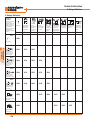
Magnetic Motor Starters / Reversing
Single Phase - Series CBUT
Single Phase, Reversing CBUTR7 (Reconnectable Winding – Three Lead Motor)
Maximum Auxiliary Open
Horsepower Contacts per Type
Single Ø Contactor ➌
115V 230V NO
D M12 (M3 ➋)
I Industrial
M Dusttight
M1
General
Purpose
D M4
I Watertight
M
D F4
I Watertight
M Corr. Resis.
D
I
M
NC Catalog No. Price Catalog No. Price ➊ Catalog No. Price ➊ Catalog No. Price ➊ Catalog No. Price ➊
1/3
1
1
1
1/2
2
1
1
1
3
1
1
2
3
1
1
2
5
1
1
CBUTR7-9
-✱-◆
CBUTR7-12
-✱-◆
CBUTR7-16
-✱-◆
CBUTR7-23
-✱-◆
CBUTR7-30
-✱-◆
255
295
320
345
425
CBUTR7-9
-✱-◆-G0
CBUTR7-12
-✱-◆-G0
CBUTR7-16
-✱-◆-G0
CBUTR7-23
-✱-◆-G0
CBUTR7-30
-✱-◆-G0
400
440
465
490
570
B CBUTR7-9
-✱-◆-D0
B CBUTR7-12
-✱-◆-D0
B CBUTR7-16
-✱-◆-D0
B CBUTR7-23
-✱-◆-D0
B CBUTR7-30
-✱-◆-D0
430
470
495
520
600
M CBUTR7-9
-✱-◆-W0
M CBUTR7-12
-✱-◆-W0
M CBUTR7-16
-✱-◆-W0
M CBUTR7-23
-✱-◆-W0
M CBUTR7-30
-✱-◆-W0
460
500
530
555
630
N CBUTR7-9
-✱-◆-C0
N CBUTR7-12
-✱-◆-C0
N CBUTR7-16
-✱-◆-C0
N CBUTR7-23
-✱-◆-C0
N CBUTR7-30
-✱-◆-C0
450
U1
490
U1
520
U1
545
U1
620
U1
Single Phase, Reversing CBUTS7 (Series Winding – Four Lead Repulsion Induction Motor)
Maximum Auxiliary Open
Horsepower Contacts per Type
Single Ø Contactor ➌
D M4
I Watertight
M
D F4
I Watertight
M Corr. Resis.
D
I
M
NC Catalog No. Price Catalog No. Price ➊ Catalog No. Price ➊ Catalog No. Price ➊ Catalog No. Price ➊
1/3
1
1
1
1/2
2
1
1
1
3
1
1
2
3
1
1
2
5
1
1
CBUTS7-9
-✱-◆
CBUTS7-12
-✱-◆
CBUTS7-16
-✱-◆
CBUTS7-23
-✱-◆
CBUTS7-30
-✱-◆
255
295
320
345
425
CBUTS7-9
-✱-◆-G0
CBUTS7-12
-✱-◆-G0
CBUTS7-16
-✱-◆-G0
CBUTS7-23
-✱-◆-G0
CBUTS7-30
-✱-◆-G0
400
440
465
490
570
B CBUTS7-9
-✱-◆-D0
B CBUTS7-12
-✱-◆-D0
B CBUTS7-16
-✱-◆-D0
B CBUTS7-23
-✱-◆-D0
B CBUTS7-30
-✱-◆-D0
430
470
495
520
600
M CBUTS7-9
-✱-◆-W0
M CBUTS7-12
-✱-◆-W0
M CBUTS7-16
-✱-◆-W0
M CBUTS7-23
-✱-◆-W0
M CBUTS7-30
-✱-◆-W0
460
500
530
555
630
N CBUTS7-9
-✱-◆-C0
N CBUTS7-12
-✱-◆-C0
N CBUTS7-16
-✱-◆-C0
N CBUTS7-23
-✱-◆-C0
N CBUTS7-30
-✱-◆-C0
450
U1
490
U1
520
U1
545
U1
MAG
620
U1
Single Phase, Reversing CBUTP7 (Parallel Winding – Four Lead Capacitor or Split Phase Motor)
Maximum Auxiliary Open
Horsepower Contacts per Type
Single Ø Contactor ➌
115V 230V NO
D M12 (M3 ➋)
I Industrial
M Dusttight
M1
General
Purpose
D M4
I Watertight
M
D F4
I Watertight
M Corr. Resis.
D
I
M
NC Catalog No. Price Catalog No. Price ➊ Catalog No. Price ➊ Catalog No. Price ➊ Catalog No. Price ➊
1/3
1
1
1
1/2
2
1
1
1
3
1
1
2
3
1
1
2
5
1
1
CBUTP7-9
-✱-◆
CBUTP7-12
-✱-◆
CBUTP7-16
-✱-◆
CBUTP7-23
-✱-◆
CBUTP7-30
-✱-◆
255
295
320
345
425
CBUTP7-9
-✱-◆-G0
CBUTP7-12
-✱-◆-G0
CBUTP7-16
-✱-◆-G0
CBUTP7-23
-✱-◆-G0
CBUTP7-30
-✱-◆-G0
400
440
465
490
570
B CBUTP7-9
-✱-◆-D0
B CBUTP7-12
-✱-◆-D0
B CBUTP7-16
-✱-◆-D0
B CBUTP7-23
-✱-◆-D0
B CBUTP7-30
-✱-◆-D0
430
470
495
520
600
M CBUTP7-9
-✱-◆-W0
M CBUTP7-12
-✱-◆-W0
M CBUTP7-16
-✱-◆-W0
M CBUTP7-23
-✱-◆-W0
M CBUTP7-30
-✱-◆-W0
460
500
530
555
630
N CBUTP7-9
-✱-◆-C0
N CBUTP7-12
-✱-◆-C0
N CBUTP7-16
-✱-◆-C0
N CBUTP7-23
-✱-◆-C0
N CBUTP7-30
-✱-◆-C0
450
U1
490
U1
520
U1
545
U1
620
U1
NOTE: Catalog numbers, list prices and enclosure dimensions reflect contactors
with AC coils. For DC coils, select Coil Code from the DC Coil Code table on page
C53 and follow the instructions for modifying catalog numbers and list prices.
Ordering Instructions
Specify Catalog Number
● Replace (✱) With Coil Code
● Replace (◆) With O/L Relay Code
●
See page C53
See pages C54-56
➊ Refer to page C79-80 for dimensional information.
➋ For M3 outdoor applications, replace "D" in catalog number with an "R". Price
remains the same, dimensions may change. Example: CBUTx7-23-✱-◆-D0
becomes CBUTx7-23-✱-◆-R0.
➌ Contactors are equipped with number and type of auxiliaries indicated. See
Modification Section to order additional or different auxiliary contacts.
Discount Schedule A-1
C
Starters &
Enclosed Prod.
115V 230V NO
D M12 (M3 ➋)
I Industrial
M Dusttight
M1
General
Purpose
C25
Magnetic Motor Starters
Series CAT
Notes
Starters &
Enclosed Prod.
C
MAG
C26
Discount Schedule A-1
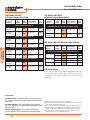
Reduced Voltage
Starters
Controlled starting for
low inrush and smooth
operation
Sprecher + Schuh reduced voltage
starters are designed for starting
squirrel cage induction motors where
the starting current of a motor is likely
to exceed local power company
restrictions, interfere with plant
operations or where the load may be
damaged by high starting torques.
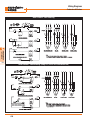
Starting with the best
Reduced Voltage Comparison Table
Type Of Starter
Starting Characteristics
Voltage
Line
Starting
@ Motor Current Torque
Across-The-Line
100%
100%
100%
Autotransformer
80%
65%
50%
64%
42%
25%
64%
42%
25%
Part Winding
100%
65%
42%
Wye-Delta
100%
33%
33%
Advantages
Disadvantages
•Least expensive.
•Simple to maintain.
•Highest starting torque.
•Readily available.
•Lowest installation cost.
•Provides highest torque per ampere
of line current.
•Three different taps on transformer
permit adjustment of starting voltage.
•Suitable for long starting periods.
•Closed transition starting.
•Uses standard motor.
•Least expensive of all reduced
voltage starters.
•Closed transition starting.
•Small physical size.
•Most dual voltage motors can be used.
•Simple design.
•Low installation cost.
•Suitable for high inertia, long
acceleration loads.
•High torque efficiency.
•Ideal for especially stringent
inrush restrictions.
•Ideal for frequent starts.
•High starting inrush may exceed
limits of local utility or elec. system.
•Starting torque may be too high for
the application.
•Limited to smaller horsepower motors.
•In lower horsepowers, is the most
expensive design.
•Low power factor.
•Large physical size.
•High installation cost.
Autotransformer Starter – At starting,
three autotransformers (one for each
phase) are automatically connected in
series with the motor. The voltage at
the motor is reduced to either 50%,
65% or 80% depending on which
voltage tap was selected. After a timed
interval, a contactor connects the
motor across-the-line and shorts out
the autotransformers. Factory standard
autotransformers are rated for
“medium duty” as defined by NEMA.
Part Winding Starter – This type of
starting requires that the motor
winding be in two equal parts, and
that at least six terminal leads be
provided on the motor. At starting, the
controller is arranged to connect one
section of the winding to the supply
lines. After a timed interval, a second
contactor connects the other section of
the motor winding to the supply lines,
in parallel with the first.
Wye-Delta Starter – This type of
starting requires a special wye-delta
motor. Both ends of the motor’s three
windings are brought out so they are
accessible for reconnecting from wye
to delta. At starting, the controller
connects the motor in the wye
configuration. After a timed interval, a
second contactor connects the motor
in a delta configuration.
The reference chart at the right
compares all three reduced voltage
starting methods and contrasts them
with across-the-line starting.
•Poor torque efficiency.
•Unsuited for high inertia, long
starting loads.
•Motor may not accelerate during
start period.
•Requires special motor design for
voltages higher than 230 volts.
•Requires special motor design.
•Low starting torque.
•Open transition (closed available).
•Complex design.
C41
C
Starters &
Enclosed Prod.
All Sprecher + Schuh reduced voltage
starters feature our CAT7, CAT6 and
CAT5 line of motor starters. These
compact starters offer intermediate
sizes to better match specific motor
requirements. This equates to generous
wiring space and less wasted
horsepower capacity. Our advanced
CEP7 solid state overload relays are
used with starters up to 180A. Larger
starters are equipped with Sprecher +
Schuh’s sophisticated CEF1 Electronic
Motor Protector, which also utilizes solid
state technology to provide an extremely
accurate thermal image of the motor.
The CEF1 includes many standard
features including digital slide switches,
LED diagnostics and single phase /
phase unbalance protection.
Combination starters are also available
with MCP or fusible Motor Circuit
Switch.
Choosing the right reduced
voltage method
R.VLT
Reduced Voltage Starters
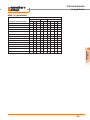
Autotransformer - Series CAAT
Autotransformer 10 HP to 125 HP (Closed Transition - M1 General Purpose Enclosure) ➍
Maximum
H.P.
10
15
20
25
30
Starters &
Enclosed Prod.
C
40
50
R.VLT
60
75
100
125
3Ø
Volts
Without
Short Circuit
Protection
D
With
I MCP Motor Circuit
M Amps Protector (MCP)
Catalog Number
Price ➊
D Fuse With
I Clip Fusible
M Amps Disconnect ➋
D
I
M
Catalog Number
Price ➊
➌
Catalog Number
Price ➊
200
CAATBA7-37-✱-◆-G0
2253
F
50
CAATBA7-37-✱-◆-B50G0
2897
S
60
CAATBA7-37-✱-◆-F22G0
2665
S
230
CAATBB7-37-✱-◆-G0
2253
F
50
CAATBB7-37-✱-◆-B50G0
2897
S
60
CAATBB7-37-✱-◆-F22G0
2665
S
200
CAATCA7-60-✱-◆-G0
2806
F
100 CAATCA7-60-✱-◆-B100G0
3449
S
60
CAATCA7-60-✱-◆-F22G0
2877
S
230
CAATCB7-43-✱-◆-G0
2348
F
50
2992
S
60
CAATCB7-43-✱-◆-F22G0
2771
S
200
CAATDA7-72-✱-◆-G0
2885
F
100 CAATDA7-72-✱-◆-B100G0
3528
S
100 CAATDA7-72-✱-◆-F23G0
2956
S
230
CAATDB7-60-✱-◆-G0
2806
F
100 CAATDB7-60-✱-◆-B100G0
3449
S
100 CAATDB7-60-✱-◆-F23G0
2877
S
200
CAATEA7-85-✱-◆-G0
2987
F
100 CAATEA7-85-✱-◆-B100G0
3630
S
100 CAATEA7-85-✱-◆-F23G0
3058
S
CAATCB7-43-✱-◆-B50G0
230
CAATEB7-72-✱-◆-G0
2885
F
100 CAATEB7-72-✱-◆-B100G0
3528
S
100 CAATEB7-72-✱-◆-F23G0
2956
S
460
CAATEC7-37-✱-◆-G0
2253
F
50
2897
S
60
2665
S
200
CAATFA6-110-✱-◆-G0
3986
H
150 CAATFA6-110-✱-◆-B150G0
5297
J
200 CAATFA6-110-✱-◆-F24G0
6163
J
230
CAATFB7-85-✱-◆-G0
2987
F
100 CAATFB7-85-✱-◆-B100G0
3630
S
100 CAATFB7-85-✱-◆-F23G0
3058
S
460
CAATFC7-43-✱-◆-G0
2348
F
50
CAATFC7-43-✱-◆-B50G0
2992
S
60
CAATFC7-43-✱-◆-F62G0
2771
S
575
CAATFD7-37-✱-◆-G0
2253
F
50
CAATFD7-37-✱-◆-B50G0
2897
S
60
CAATFD7-37-✱-◆-F62G0
2665
S
200
CAATGA6-110-✱-◆-G0
3986
H
150 CAATGA6-110-✱-◆-B150G0
5297
J
200 CAATGA6-110-✱-◆-F24G0
6163
J
230
CAATGB6-110-✱-◆-G0
3986
H
150 CAATGB6-110-✱-◆-B150G0
5297
J
200 CAATGB6-110-✱-◆-F24G0
6163
J
460
CAATGC7-60-✱-◆-G0
2806
F
100 CAATGC7-60-✱-◆-B100G0
3449
S
100 CAATGC7-60-✱-◆-F63G0
2877
S
575
CAATGD7-60-✱-◆-G0
2806
F
50
3449
S
60
CAATGD7-60-✱-◆-F62G0
2877
S
200
CAATHA6-180-✱-◆-G0
6949
I
225 CAATHA6-180-✱-◆-B225G0
8567
J
200 CAATHA6-180-✱-◆-F24G0
8871
J
230
CAATHB6-140-✱-◆-G0
5873
I
150 CAATHB6-140-✱-◆-B150G0
6827
J
200 CAATHB6-140-✱-◆-F24G0
7693
J
460
CAATHC7-72-✱-◆-G0
2885
F
100 CAATHC7-72-✱-◆-B100G0
3528
S
100 CAATHC7-72-✱-◆-F63G0
2956
S
575
CAATHD7-60-✱-◆-G0
2806
F
100 CAATHD7-60-✱-◆-B100G0
3449
S
60
2877
S
200
CAATJA6-210-EI-✱-◆-G0
10185 J
225 CAATJA6-210-EI-✱-◆-B225G0 13303 J
400 CAATJA6-210-EI-✱-◆-F25G0 12340 K3
230
CAATJB6-180-✱-◆-G0
6949
I
225 CAATJB6-180-✱-◆-B225G0
460
CAATJC7-85-✱-◆-G0
2987
F
575
CAATJD7-72-✱-◆-G0
2885
F
200
CAATKA6-250-EI-✱-◆-G0
10872 J
400 CAATKA6-250-EI-✱-◆-B400G0 13990 K2
400 CAATKA6-250-EI-✱-◆-F25G0 12798 K2
230
CAATKB6-210-EI-✱-◆-G0
10185 J
225 CAATKB6-210-EI-✱-◆-B225G0 13303 J
400 CAATKB6-210-EI-✱-◆-F25G0 12340 K3
460
CAATKC6-110-✱-◆-G0
3986
H
150 CAATKC6-110-✱-◆-B150G0
5297
J
200 CAATKC6-110-✱-◆-F64G0
6163
J
575
CAATKD6-95-✱-◆-G0
3859
H
100 CAATKD6-95-✱-◆-B100G0
5169
J
100 CAATKD6-95-✱-◆-F63G0
6036
J
200
CAATLA6-300-EI-✱-◆-G0
11871 J2
400 CAATLA6-300-EI-✱-◆-B400G0 15081 K2
400 CAATLA6-300-EI-✱-◆-F25G0 16618 K2
230
CAATLB6-250-EI-✱-◆-G0
10872 J
400 CAATLB6-250-EI-✱-◆-B400G0 13990 K2
400 CAATLB6-250-EI-✱-◆-F25G0 12798 K2
460
CAATLC6-140-✱-◆-G0
5873
I
150 CAATLC6-140-✱-◆-B150G0
6827
J
200 CAATLC6-140-✱-◆-F64G0
7693
J
575
CAATLD6-110-✱-◆-G0
3986
H
150 CAATLD6-110-✱-◆-B150G0
5297
J
200 CAATLD6-110-✱-◆-F64G0
6163
J
200
CAATMA6-420-EI-✱-◆-G0
13913 J2
600 CAATMA6-420-EI-✱-◆-B600G0 18540 K2
600 CAATMA6-420-EI-✱-◆-F26G0 18659 K2
230
CAATMB6-300-EI-✱-◆-G0
11871 J2
400 CAATMB6-300-EI-✱-◆-B400G0 15081 K2
400 CAATMB6-300-EI-✱-◆-F25G0 16618 K2
CAATEC7-37-✱-◆-B50G0
CAATGD7-60-✱-◆-B50G0
CAATEC7-37-✱-◆-F62G0
CAATHD7-60-✱-◆-F62G0
8567
J
200 CAATJB6-180-✱-◆-F24G0
8871
J
100 CAATJC7-85-✱-◆-B100G0
3630
S
100 CAATJD7-72-✱-◆-B100G0
3528
S
100 CAATJC7-85-✱-◆-F63G0
3058
S
100 CAATJD7-72-✱-◆-F63G0
2956
S
460
CAATMC6-180-✱-◆-G0
6949
I
225 CAATMC6-180-✱-◆-B225G0
8567
J
200 CAATMC6-180-✱-◆-F64G0
8871
J
575
CAATMD6-140-✱-◆-G0
5873
I
150 CAATMD6-140-✱-◆-B150G0
6827
J
200 CAATMD6-140-✱-◆-F64G0
7693
J
Larger Horsepowers Continued On Next Page ➟
NOTE: Catalog numbers, list prices and enclosure dimensions reflect contactors
with AC coils. For DC coils, select Coil Code from the DC Coil Code table on page
C53 and follow the instructions for modifying catalog numbers and list prices.
Ordering Instructions
Specify Catalog Number
● Replace (✱) With Coil Code
● Replace (◆) With O/L Relay Code
●
C42
See page C53
See pages C54-56
➊ Refer to page C79-80 for dimensional information.
➋ For Non-fusible Disconnect applications, replace the "F6" or "F2" characters with
"U6". Example: CAATHC7-72-✱-◆-F63G0 becomes CAATHC7-72-✱-◆-U63G0.
➌ Fuse clips sized for use with “J”-type fuses.
➍ Other enclosures available. See Factory Modifications in this section.
Discount Schedule A-5
Reduced Voltage Starters
Autotransformer - Series CAAT
Autotransformer 150 HP to 1000 HP (Closed Transition - M1 General Purpose Enclosure) ➍
Maximum
H.P.
150
200
250
300
400
450
500
600
Without
Short Circuit
Protection
D
With
I MCP Motor Circuit
M Amps Protector (MCP)
D Fuse With
I Clip Fusible
M Amps Disconnect ➋
Catalog Number
Price ➊
200
CAATNA6-420-EI-✱-◆-G0
13913 J2
600 CAATNA6-420-EI-✱-◆-B600G0 18540 K2
600 CAATNA6-420-EI-✱-◆-F26G0 18659 K2
230
CAATNB6-420-EI-✱-◆-G0
13913 J2
600 CAATNB6-420-EI-✱-◆-B600G0 18540 K2
600 CAATNB6-420-EI-✱-◆-F26G0 18659 K2
460
CAATNC6-180-✱-◆-G0
6949
225 CAATNC6-180-✱-◆-B225G0
8567
400 CAATNC6-180-✱-◆-F65G0
8871 K3
575
CAATND6-180-✱-◆-G0
6949
I
225 CAATND6-180-✱-◆-B225G0
8567
J
200 CAATND6-18-✱-◆-F64G0
8871
J
230
CAATOB6-630-✱-◆-G0
R/F
~
600 CAATOB5-700-✱-◆-B600G0
R/F
~
600 CAATOB5-700-✱-◆-F26G0
R/F
~
460
CAATOC6-250-EI-✱-◆-G0
10872 J
400 CAATOC6-250-EI-✱-◆-B400G0 13990 K2
400 CAATOC6-250-EI-✱-◆-F65G0 12798 K2
575
CAATOD6-210-EI-✱-◆-G0
10185 J
225 CAATOD6-210-EI-✱-◆-B225G0 13303 J
400 CAATOD6-210-EI-✱-◆-F65G0 12340 K3
230
CAATPB6-630-✱-◆-G0
460
CAATPC6-300-EI-✱-◆-G0
11871 J2
400 CAATPC6-300-EI-✱-◆-B400G0 15081 K2
400 CAATPC6-300-EI-✱-◆-F65G0 16618 K2
575
CAATPD6-250-EI-✱-◆-G0
10872 J
400 CAATPD6-250-EI-✱-◆-B400G0 13990 K2
400 CAATPD6-250-EI-✱-◆-F65G0 12798 K2
230
CAATQB6-860-✱-◆-G0
460
CAATQC6-420-EI-✱-◆-G0
13913 J2
600 CAATQC6-420-EI-✱-◆-B600G0 18540 K2
600 CAATQC6-420-EI-✱-◆-F66G0 18659 K2
575
CAATQD6-300-EI-✱-◆-G0
11871 J2
400 CAATQD6-300-EI-✱-◆-B400G0 15081 K2
400 CAATQD6-300-EI-✱-◆-F65G0 16618 K2
230
Refer To Factory
460
CAATRC6-420-EI-✱-◆-G0
13913 J2
600 CAATRC6-420-EI-✱-◆-B600G0 18540 K2
600 CAATRC6-420-EI-✱-◆-F66G0 18659 K2
575
CAATRD6-420-EI-✱-◆-G0
13913 J2
600 CAATRD6-420-EI-✱-◆-B600G0 18540 K2
600 CAATRD6-420-EI-✱-◆-F66G0 18659 K2
230
Refer To Factory
460
CAATSC6-630-✱-◆-G0
575
CAATSD6-420-EI-✱-◆-G0
230
Refer To Factory
R/F
R/F
I
~
~
Catalog Number
J
Refer To Factory
Refer To Factory
Refer To Factory
~
13913 J2
600 CAATSC6-630-✱-◆-B600G0
Price ➊
Catalog Number
Refer To Factory
Refer To Factory
R/F
➌
Refer To Factory
Refer To Factory
Refer To Factory
R/F
~
600 CAATSD6-420-EI-✱-◆-B600G0 18540 K2
600 CAATSC6-630-✱-◆-F66G0
R/F
~
460
CAATTC6-630-✱-◆-G0
R/F
~
CAATTD6-630-✱-◆-G0
R/F
~
R.VLT
Refer To Factory
460
CAATUC6-630-✱-◆-G0
R/F
~
575 ➎
CAATUD6-630-✱-◆-G0
R/F
~
460
CAATVC6-860-✱-◆-G0
R/F
~
Refer To Factory
575 ➎
CAATVD6-860-✱-◆-G0
R/F
~
Refer To Factory
600 CAATTD6-630-✱-◆-B600G0
R/F
~
Refer To Factory
Refer To Factory
600 CAATUD6-630-✱-◆-B600G0
Larger sizes available. Contact your Sprecher + Schuh representative.
Ordering Instructions
●
See page C53
See pages C56
R/F
~
NOTE: Catalog numbers, list prices and enclosure dimensions reflect contactors
with AC coils. For DC coils, select Coil Code from the DC Coil Code table on page
C53 and follow the instructions for modifying catalog numbers and list prices.
➊ Refer to page C79-80 for dimensional information.
➋ For Non-fusible Disconnect applications, replace the "F6" or "F2" characters with
"U6". Example: CAATNC6-170-EI-✱-◆-F65G0 becomes
CAATNC6-170-EI-✱-◆-U65G0.
➌ Fuse clips sized for use with “J”-type fuses.
➍ Other enclosures available. See Factory Modifications in this section.
➎ Pending UL Approval. Contact your Sprecher + Schuh representative.
Discount Schedule A-5
C
600 CAATSD6-420-EI-✱-◆-F66G0 18659 ~
Refer To Factory
575 ➎
Specify Catalog Number
● Replace (✱) With Coil Code
● Replace (◆) With O/L Relay Code
Price ➊
D
I
M
Starters &
Enclosed Prod.
350
3Ø
Volts
C43
Reduced Voltage Starters
Part Winding - Series CAPWT
Part Winding (Two Step)
D M12 (M3 ➋)
I Industrial
M Dusttight
Maximum Horsepower M1
Three Phase
General
Purpose
Price ➊ Catalog Number
200V 230V 460V 575V Catalog Number
Starters &
Enclosed Prod.
C
10
15
20
25
30
40
60
~
75
~
100
150
200
300
15
~
20
30
40
50
60
75
~
100
150
200
250
400
30
40
50
60
75
100
100
150
200
~
300
350
500
750
D M4
I Watertight
M
CAPWT
30 7-30-✱-◆-G0
40 7-37-✱-◆-G0
50 7-43-✱-◆-G0
75 7-60-✱-◆-G0
100 7-72-✱-◆-G0
125 7-85-✱-◆-G0
150 6-110-✱-◆-G0
200 6-140-✱-◆-G0
~ 6-180-EI-✱-◆-G0
300 6-210-EI-✱-◆-G0
350 6-250-EI-✱-◆-G0
450 6-300-EI-✱-◆-G0
600 6-420-EI-✱-◆-G0
750➍ 6-630-✱-◆-G0
950
1100
1275
1450
1550
2000
3250
4750
5500
8400
9500
11500
15350
R/F
M
M
M
C
C
C
E
F
H
H
J
J
J
~
CAPWT
7-30-✱-◆-D0
7-37-✱-◆-D0
7-43-✱-◆-D0
7-60-✱-◆-D0
7-72-✱-◆-D0
7-85-✱-◆-D0
6-110-✱-◆-D0
6-140-✱-◆-D0
6-180-EI-✱-◆-D0
6-210-EI-✱-◆-D0
6-250-EI-✱-◆-D0
6-300-EI-✱-◆-D0
6-420-EI-✱-◆-D0
6-630-✱-◆-D0
Larger sizes available. Contact your Sprecher + Schuh representative.
Price ➊ Catalog Number
1000
1150
1325
1500
1600
2050
4250
5500
6000
8900
10000
12000
15850
R/F
M
M
M
O
O
O
R
T
H
H
J
J
J
~
CAPWT
7-30-✱-◆-W0
7-37-✱-◆-W0
7-43-✱-◆-W0
7-60-✱-◆-W0
7-72-✱-◆-W0
7-85-✱-◆-W0
6-110-✱-◆-W0
6-140-✱-◆-W0
6-180-EI-✱-◆-W0
6-210-EI-✱-◆-W0
6-250-EI-✱-◆-W0
6-300-EI-✱-◆-W0
6-420-EI-✱-◆-W0
6-630-✱-◆-W0
D F4
I Watertight
M Corrosion Resist
Price ➊ Catalog Number
1225
1575
1800
1995
2150
2595
4990
7500
7995
10500
11250
12200
16750
R/F
M
M
M
O
O
O
R
T
H
H
J
J
J
~
CAPWT
7-30-✱-◆-C0
7-37-✱-◆-C0
7-43-✱-◆-C0
7-60-✱-◆-C0
7-72-✱-◆-C0
7-85-✱-◆-C0
6-110-✱-◆-C0
6-140-✱-◆-C0
6-180-EI-✱-◆-C0
6-210-EI-✱-◆-C0
6-250-EI-✱-◆-C0
6-300-EI-✱-◆-C0
6-420-EI-✱-◆-C0
6-630-✱-◆-C0
D
I
M
Price ➊
1225
1575
1800
1995
2150
2595
4990
7500
7995
10500
11250
12200
16750
R/F
U1
U1
U1
V1
V1
V1
W2
A2
Y1
Y1
Z1
Z1
Z1
~
NOTE: Catalog numbers, list prices and enclosure dimensions reflect contactors
with AC coils. For DC coils, select Coil Code from the DC Coil Code table on page
C53 and follow the instructions for modifying catalog numbers and list prices.
Combination Part Winding Starter Adder Chart ➌
Price (Add to base Part Winding starter list price)
R.VLT
Circuit Breaker or
Disconnect Switch
Enclosure
Type
7-30
7-37
7-43
Motor Circuit Protector
M1
M4/F4,M12/3
M1
M4/F4,M12/3
M1
M4/F4,M12/3
M1
M4/F4,M12/3
M1
M4/F4,M12/3
M1
M4/F4,M12/3
M1
M4/F4,M12/3
M1
M4/F4,M12/3
688
720
480
512
512
544
596
628
~
~
~
~
~
~
~
~
748
804
608
664
~
~
656
712
836
1104
~
~
~
~
~
~
Non Fusible Disconnect
Fusible Disconnect - 30 Amp
Fusible Disconnect - 60 Amp
Fusible Disconnect - 100 Amp
Fusible Disconnect - 200 Amp
Fusible Disconnect - 400 Amp
Fusible Disconnect - 600 Amp
Ordering Instructions
Specify Catalog Number
● Replace (✱) With Coil Code
●
●
Multiply Motor FLA By 50%,
Replace (◆) With O/L Relay Code
C44
See page C53
See pages C54-56
7-60
7-72
7-85
6-95(-EI)
6-110(-EI)
6-140(-EI)
6-180(-EI)
6-210-EI
6-250-EI
1368
1848
840
1352
~
~
~
~
1016
1496
1448
1560
~
~
~
~
2660
3044
1504
1664
~
~
~
~
~
~
1648
1808
2212
2372
~
~
3916
4216
3452
3752
~
~
~
~
~
~
~
~
3876
4176
4332
4932
6-300-EI
6-420-EI
5-700
5-860
5-1000
5-1200
Contact factory for pricing.
➊ Refer to page C79-80 for dimensional information.
➋ For M3 outdoor applications, replace "D" in catalog number with an "R". Price
remains the same, dimensions may change. Example: CAPWT7-30-✱-◆-D0
becomes CAPWT7-30-✱-◆-R0.
➌ Refer to page C3 for information on modifying standard Part Winding catalog
number to combination type.
➍ Pending UL Approval. Contact your Sprecher + Schuh representative.
Discount Schedule A-5
Reduced Voltage Starters
Wye Delta - Series CAYT
Wye Delta (Open Transition ➍)
D M12 (M3 ➋)
I Industrial
M Dusttight
Maximum Horsepower M1
Three Phase
General
Purpose
Price ➊ Catalog Number
200V 230V 460V 575V Catalog Number
10
15
20
30
40
50
60
~
75
100
125
175
250
350
15
20
25
40
50
60
~
75
100
125
175
200
250
450
30
40
50
75
100
125
~
175
200
250
350
450
600
800
D M4
I Watertight
M
CAYT
30 7-30-✱-◆-G0
40 7-37-✱-◆-G0
50 7-43-✱-◆-G0
75 7-60-✱-◆-G0
100 7-72-✱-◆-G0
125 7-85-✱-◆-G0
150 6-110-✱-◆-G0
200 6-140-✱-◆-G0
250 6-180-✱-◆-G0
300 6-210-EI-✱-◆-G0
450 6-250-EI-✱-◆-G0
500 6-300-EI-✱-◆-G0
650 6-420-EI-✱-◆-G0
800➎ 6-630-✱-◆-G0
900
1325
1450
1695
2000
2200
2750
4400
5500
8150
9250
9950
13500
R/F
C
C
C
D
F
F
F
F
H
I
J
J
J
~
CAYT
7-30-✱-◆-D0
7-37-✱-◆-D0
7-43-✱-◆-D0
7-60-✱-◆-D0
7-72-✱-◆-D0
7-85-✱-◆-D0
6-110-✱-◆-D0
6-140-✱-◆-D0
6-180-✱-◆-D0
6-210-EI-✱-◆-D0
6-250-EI-✱-◆-D0
6-300-EI-✱-◆-D0
6-420-EI-✱-◆-D0
6-630-✱-◆-D0
925
1350
1475
1900
2450
2650
3100
4750
5800
8250
9350
10050
13600
R/F
O
O
O
Q
T
T
T
T
H
I
J
J
J
~
Price ➊ Catalog Number
CAYT
7-30-✱-◆-W0
1200 O
7-37-✱-◆-W0
1625 O
7-43-✱-◆-W0
1750 O
7-60-✱-◆-W0
2175 Q
7-72-✱-◆-W0
2750 T
7-85-✱-◆-W0
3000 T
6-110-✱-◆-W0
3800 T
6-140-✱-◆-W0
5450 T
6-180-✱-◆-W0
6800 H
6-210-EI-✱-◆-W0 8790 J
6-250-EI-✱-◆-W0 9500 J
6-300-EI-✱-◆-W0 10932 J
6-420-EI-✱-◆-W0 16070 J
6-630-✱-◆-W0
R/F ~
CAYT
7-30-✱-◆-C0
7-37-✱-◆-C0
7-43-✱-◆-C0
7-60-✱-◆-C0
7-72-✱-◆-C0
7-85-✱-◆-C0
6-110-✱-◆-C0
6-140-✱-◆-C0
6-180-✱-◆-C0
6-210-EI-✱-◆-C0
6-250-EI-✱-◆-C0
6-300-EI-✱-◆-C0
6-420-EI-✱-◆-C0
6-630-✱-◆-C0
D
I
M
Price ➊
1200
1600
1750
1900
3500
3700
5610
6975
8075
10110
10590
11250
14930
R/F
V1
V1
V1
W1
X1
X1
A2
A2
Y1
Z1
Z1
Z1
Z1
~
NOTE: Catalog numbers, list prices and enclosure dimensions reflect contactors
with AC coils. For DC coils, select Coil Code from the DC Coil Code table on page
C53 and follow the instructions for modifying catalog numbers and list prices.
Combination Wye Delta Starter Adder Chart ➌
Price (Add to base Wye Delta starter list price)
Circuit Breaker or
Disconnect Switch
Enclosure
Type
7-30
7-37
7-43
Motor Circuit Protector
M1
M4/F4,M12/3
M1
M4/F4,M12/3
M1
M4/F4,M12/3
M1
M4/F4,M12/3
M1
M4/F4,M12/3
M1
M4/F4,M12/3
M1
M4/F4,M12/3
M1
M4/F4,M12/3
688
720
480
512
512
544
656
712
~
~
~
~
~
~
~
~
748
804
608
664
~
~
656
712
1016
1496
~
~
~
~
~
~
Non Fusible Disconnect
Fusible Disconnect - 30 Amp
Fusible Disconnect - 60 Amp
Fusible Disconnect - 100 Amp
Fusible Disconnect - 200 Amp
Fusible Disconnect - 400 Amp
Fusible Disconnect - 600 Amp
Ordering Instructions
Specify Catalog Number
● Replace (✱) With Coil Code
●
●
Multiply Motor FLA By 58%,
Replace (◆) With O/L Relay Code
See page C53
See pages C54-56
7-60
7-72
7-85
6-95(-EI)
6-110(-EI)
6-140(-EI)
6-180(-EI)
6-210-EI
6-250-EI
6-300-EI
6-420-EI
1368
1848
840
1352
~
~
~
~
1016
1496
1648
1808
~
~
~
~
2660
3044
1504
1664
~
~
~
~
~
~
1648
1808
3876
4176
~
~
3916
4216
3452
3752
~
~
~
~
~
~
~
~
3876
4176
4076
4276
5428
5728
3652
3952
~
~
~
~
~
~
~
~
~
~
4076
4276
R.VLT
5-700
5-860
5-1000
5-1200
Contact factory for
pricing.
➊ Refer to page C79-80 for dimensional information.
➋ For M3 outdoor applications, replace "D" in catalog number with an "R". Price
remains the same, dimensions may change. Example: CAYT7-30-✱-◆-D0
becomes CAYT7-30-✱-◆-R0.
➌ Refer to page C3 for information on modifying standard Wye Delta catalog number
to combination type.
➍ For closed transition Wye Delta applications, please contact factory.
➎ Pending UL Approval. Contact your Sprecher + Schuh representative.
Discount Schedule A-5
C
Starters &
Enclosed Prod.
Larger sizes available. Contact your Sprecher + Schuh representative.
Price ➊ Catalog Number
D F4
I Watertight
M Corrosion Resist
C45
Reduced Voltage Starters
Series CA…
Notes
Starters &
Enclosed Prod.
C
R.VLT
C46
Discount Schedule A-5
Combination
Starters
Smart and
cost effective…
for any application
Sprecher + Schuh combination starters
are, by design, intended to eliminate the
purchase and assembly of a separate disconnect, starter, enclosure and associated
wiring. The end result is a cost effective
assembly, cleanly wired and ready for
installation.
Starting with the best
At the heart of all combination starters is
the Sprecher + Schuh CAT7, CAT6 and
CAT5 line of motor starters. These starters are compact and offer intermediate
sizes to better match specific motor requirements. This equates to generous
wiring space and less wasted horsepower
capacity.
Top line protection…
Larger starters are equipped with
Sprecher + Schuh’s sophisticated CEF1
Electronic Motor Protector, which also
utilizes solid state technology to provide
an extremely accurate thermal image of
the motor. The CEF1 includes many
standard features including digital slide
switches, LED diagnostics and single
phase / phase unbalance protection.
Circuit protection right for your
application
Choices for disconnect include either a
Motor Circuit Protector (MCP), or Motor Circuit Switch (MCS), fusible or nonfusible. The Motor Circuit Protector is
an adjustable “magnetic trip only” circuit
breaker for precise protection of motor
circuits. An MCP prevents single phasing
by simultaneously opening all three phas-
C
Starters &
Enclosed Prod.
Combination starters (up to 180A) are
equipped with Sprecher + Schuh’s new
CEP7 solid state overload relay. Unlike
traditional overload relays that indirectly
sense motor current through heater
elements, CEP7 solid state overload
relays measure motor current directly
through integrated current transformers
and on board electronics. The electronics provide numerous advantages over
electromechanical relays.
es when a fault occurs in any one phase.
An MCP can also be quickly reset after
the fault has been cleared. Interrupting
capacity can be increased to 100,000
amperes by adding a current limiter
(contact factory for this option).
Motor Circuit Switch disconnects have a
quick make/quick break, non-teasing
COMB
action. The three blades are visible for
positive indication of an open circuit.
The fusible MCS is suitable for interrupting up to 100,000 amperes when class
“R” type fuse clips and fuses are used
(contact factory for this option).
Convenience and safety
Disconnect mechanisms are flangemounted or through-the-door for simple
operation during start-up or maintenance. A mechanical door interlock system prevents the door from being
opened when the disconnect is closed,
and conversely, prevents the disconnect
from being closed when the door is open.
Both functions can be defeated for test
and maintenance purposes. Other safety
features include padlock provisions and a
high visibility operating handle.
Available enclosures include M1 General
Purpose, M3R Raintight, M12 Dusttight
and M4/F4 Watertight.
C27
Combination Starters
Motor Circuit Protector - Series CAT
Series CAT7, CAT6 & CAT5 with Motor Circuit Protector (MCP)
D M12 (M3 ➋)
I Industrial
M Dusttight
Maximum Horsepower
M1
Three Phase
MCP General
Amps Purpose
200V 230V 460V 575V
Catalog Number
D M4
I Watertight
M
D F4
I Watertight
M Corrosion Resist
Price ➊ Catalog Number
Price ➊ Catalog Number
Price ➊ Catalog Number
CAT
CAT
CAT
Price ➊
1/2
1/2
1
1 1/2
3
7-30-✱-◆-B3G0
915
X
7-30-✱-◆-B3D0
1135
Y
7-30-✱-◆-B3W0
1420
Q 7-30-✱-◆-B3C0
1145 V1
1
1
3
3
7
7-30-✱-◆-B7G0
915
X
7-30-✱-◆-B7D0
1135
Y
7-30-✱-◆-B7W0
1420
Q 7-30-✱-◆-B7C0
1145 V1
3
3
7 1/2
10
15
7-30-✱-◆-B15G0
915
X
7-30-✱-◆-B15D0
1135
Y
7-30-✱-◆-B15W0
1420
Q 7-30-✱-◆-B15C0
1145 V1
5
7 1/2
15
20
30
7-30-✱-◆-B30G0
915
X
7-30-✱-◆-B30D0
1135
Y
7-30-✱-◆-B30W0
1420
Q 7-30-✱-◆-B30C0
1145 V1
7 1/2
10
20
25
50
7-30-✱-◆-B50G0
945
X
7-30-✱-◆-B50D0
1165
Y
7-30-✱-◆-B50W0
1420
Q 7-30-✱-◆-B50C0
1145 V1
10
~
25
30
50
7-37-✱-◆-B50G0
975
X
7-37-✱-◆-B50D0
1195
Y
7-37-✱-◆-B50W0
1450
Q 7-37-✱-◆-B50C0
1200 V1
~
15
30
~
50
7-43-✱-◆-B50G0
1015
X
7-43-✱-◆-B50D0
1235
Y
7-43-✱-◆-B50W0
1490
Q 7-43-✱-◆-B50C0
1415 V1
~
~
~
40
50
7-60-✱-◆-B50G0
1075
X
7-60-✱-◆-B50D0
1295
Y
7-60-✱-◆-B50W0
1550
Q 7-60-✱-◆-B50C0
1475 W1
C
15
20
40
50
100
7-60-✱-◆-B100G0 1120
X
7-60-✱-◆-B100D0 1340
Y
7-60-✱-◆-B100W0 1615
Q 7-60-✱-◆-B100C0 1540 W1
20
25
50
60
100
7-72-✱-◆-B100G0 1155
X
7-72-✱-◆-B100D0 1375
Y
7-72-✱-◆-B100W0 1650
Q 7-72-✱-◆-B100C0 1575 W1
Starters &
Enclosed Prod.
CAT
D
I
M
25
30
60
~
100
7-85-✱-◆-B100G0 1190
X
7-85-✱-◆-B100D0 1410
Y
7-85-✱-◆-B100W0 1685
Q 7-85-✱-◆-B100C0 1610 W1
~
~
~
75
100
6-95-✱-◆-B100G0 1682
E
6-95-✱-◆-B100D0 1907
R 6-95-✱-◆-B100W0 2162
R 6-95-✱-◆-B100C0 2952 X1
40
40
75
100
150
6-110-✱-◆-B150G0 1882
E
6-110-✱-◆-B150D0 2107
R 6-110-✱-◆-B150W0 2392
R
6-110-✱-◆-B150C0 3182 X1
~
50
100
125
150
6-140-✱-◆-B150G0 2322
F
6-140-✱-◆-B150D0 2597
T
6-140-✱-◆-B150W0 2932
T
6-140-✱-◆-B150C0 3507 X1
COMB
50
60
150
150
225
6-180-✱-◆-B225G0
F
6-180-✱-◆-B225D0
T
6-180-✱-◆-B225W0
T
6-180-✱-◆-B225C0
60
75
~
200
225
6-210-EI-✱-◆-B225G0 4438
H 6-210-EI-✱-◆-B225D0 4763
75
100
200
250
400
6-250-EI-✱-◆-B400G0 6928
I
6-250-EI-✱-◆-B400D0 7088 W 6-250-EI-✱-◆-B400W0 7888
J
6-250-EI-✱-◆-B400C0 8238 Y1
100
125
250
300
400
6-300-EI-✱-◆-B400G0 7078
I
6-300-EI-✱-◆-B400D0 7238 W 6-300-EI-✱-◆-B400W0 8038
J
6-300-EI-✱-◆-B400C0 8388 Y1
150
175
350
400
600
6-420-EI-✱-◆-B600G0 10078 I
6-420-EI-✱-◆-B600D0 10238 W 6-420-EI-✱-◆-B600W0 11038 J
6-420-EI-✱-◆-B600C0 11388 Y1
~
200
400 500➌ 600
6-630-✱-◆-B600G0
R/F
J
6-630-✱-◆-B600D0
R/F
J
6-630-✱-◆-B600W0
R/F
J
6-630-✱-◆-B600C0
R/F
~
200
250
500
6-630-✱-◆-B800G0
R/F
~ 6-630-✱-◆-B800D0
R/F
~ 6-630-✱-◆-B800W0
R/F
~ 6-630-✱-◆-B800C0
R/F
~
~
800
3572
3572
4072
H 6-210-EI-✱-◆-B225W0 4738
4972 A2
H 6-210-EI-✱-◆-B225C0 5788 Y1
Larger sizes available. Contact your Sprecher + Schuh representative.
NOTE: Catalog numbers, list prices and enclosure dimensions reflect contactors
with AC coils. For DC coils, select Coil Code from the DC Coil Code table on page
C53 and follow the instructions for modifying catalog numbers and list prices.
Ordering Instructions
Specify Catalog Number
● Replace (✱) With Coil Code
● Replace (◆) With O/L Relay Code
●
C28
See page C53
See pages C54-56
➊ Refer to page C79-80 for dimensional information.
➋ For M3 outdoor applications, replace "D" in catalog number with an "R".
Price remains the same, dimensions may change. Example: CAT7-30-✱-◆-B30D0
becomes CAT7-30-✱-◆-B30R0.
➌ Pending UL Approval. Contact your Sprecher + Schuh representative.
Discount Schedule A-2
Combination Starters - Reversing
Motor Circuit Protector - Series CAUT
Series CAUT7, CAUT6 & CAUT5 with Motor Circuit Protector (MCP)
D M12 (M3 ➋)
I Industrial
M Dusttight
Maximum Horsepower
M1
Three Phase
MCP General
Amps Purpose
200V 230V 460V 575V
Catalog Number
D M4
I Watertight
M
D F4
I Watertight
M Corrosion Resist
Price ➊ Catalog Number
Price ➊ Catalog Number
Price ➊ Catalog Number
CAUT
CAUT
CAUT
CAUT
D
I
M
Price ➊
1/2
1/2
1
1 1/2
3
7-30-✱-◆-B3G0
1095
X
7-30-✱-◆-B3D0
1315
Y
7-30-✱-◆-B3W0
1625
Q 7-30-✱-◆-B3C0
1350 V1
1
1
3
3
7
7-30-✱-◆-B7G0
1095
X
7-30-✱-◆-B7D0
1315
Y
7-30-✱-◆-B7W0
1625
Q 7-30-✱-◆-B7C0
1350 V1
3
3
7 1/2
10
15
7-30-✱-◆-B15G0
1095
X
7-30-✱-◆-B15D0
1315
Y
7-30-✱-◆-B15W0
1625
Q 7-30-✱-◆-B15C0
1350 V1
5
7 1/2
15
20
30
7-30-✱-◆-B30G0
1095
X
7-30-✱-◆-B30D0
1315
Y
7-30-✱-◆-B30W0
1625
Q 7-30-✱-◆-B30C0
1350 V1
7 1/2
10
20
25
50
7-30-✱-◆-B50G0
1125
X
7-30-✱-◆-B50D0
1345
Y
7-30-✱-◆-B50W0
1625
Q 7-30-✱-◆-B50C0
1350 V1
10
~
25
30
50
7-37-✱-◆-B50G0
1180
X
7-37-✱-◆-B50D0
1400
Y
7-37-✱-◆-B50W0
1680
Q 7-37-✱-◆-B50C0
1405 V1
~
15
30
~
50
7-43-✱-◆-B50G0
1270
X
7-43-✱-◆-B50D0
1490
Y
7-43-✱-◆-B50W0
1770
Q 7-43-✱-◆-B50C0
1695 V1
~
~
~
40
50
7-60-✱-◆-B50G0
1390
X
7-60-✱-◆-B50D0
1610
Y
7-60-✱-◆-B50W0
1890
Q 7-60-✱-◆-B50C0
1815 W1
15
20
40
50
100
7-60-✱-◆-B100G0 1435
X
7-60-✱-◆-B100D0 1655
Y
7-60-✱-◆-B100W0 1955
Q 7-60-✱-◆-B100C0 1880 W1
20
25
50
60
100
7-72-✱-◆-B100G0 1505
X
7-72-✱-◆-B100D0 1725
Y
7-72-✱-◆-B100W0 2025
Q 7-72-✱-◆-B100C0 1950 W1
25
30
60
~
100
7-85-✱-◆-B100G0 1570
X
7-85-✱-◆-B100D0 1790
Y
7-85-✱-◆-B100W0 2090
Q 7-85-✱-◆-B100C0 2015 W1
~
~
~
75
100
6-95-✱-◆-B100G0 2528
F
6-95-✱-◆-B100D0 2803
T
6-95-✱-◆-B100W0 3133
T
6-95-✱-◆-B100C0 4033 A2
40
40
75
100
150
6-110-✱-◆-B150G0 2703
F
6-110-✱-◆-B150D0 2978
T
6-110-✱-◆-B150W0 3338
T
6-110-✱-◆-B150C0 4238 A2
~
50
100
125
150
6-140-✱-◆-B150G0 3553
H 6-140-✱-◆-B150D0 3878
H 6-140-✱-◆-B150W0 4298
H 6-140-✱-◆-B150C0 5038 Y1
Starters &
Enclosed Prod.
50
60
150
150
225
6-180-✱-◆-B225G0 5103
H 6-180-✱-◆-B225D0 5428
H 6-180-✱-◆-B225W0 5743
H 6-180-✱-◆-B225C0 6483 Y1
COMB
60
75
~
200
225
6-210-EI-✱-◆-B225G0 6180
H 6-210-EI-✱-◆-B225D0 6505
H 6-210-EI-✱-◆-B225W0 6820
H 6-210-EI-✱-◆-B225C0 7560 Y1
75
100
200
250
400
6-250-EI-✱-◆-B400G0 9055
J
6-250-EI-✱-◆-B400D0 9155
J
6-250-EI-✱-◆-B400W0 9830
J
6-250-EI-✱-◆-B400C0 10305 Z1
100
125
250
300
400
6-300-EI-✱-◆-B400G0 9280
J
6-300-EI-✱-◆-B400D0 9380
J
6-300-EI-✱-◆-B400W0 10055 J
6-300-EI-✱-◆-B400C0 10530 Z1
115
135
275
350
600
6-420-EI-✱-◆-B600G0 14155 J
6-420-EI-✱-◆-B600D0 14255 J
6-420-EI-✱-◆-B600W0 11455 J
6-420-EI-✱-◆-B600C0 11930 Z1
~
200
400 500➌ 600
6-630-✱-◆-B600G0
R/F
~ 6-630-✱-◆-B600D0
R/F
~ 6-630-✱-◆-B600W0
R/F
~ 6-630-✱-◆-B600C0
R/F
~
200
250
500
6-630-✱-◆-B800G0
R/F
~ 6-630-✱-◆-B800D0
R/F
~ 6-630-✱-◆-B800W0
R/F
~ 6-630-✱-◆-B800C0
R/F
~
~
800
Larger sizes available. Contact your Sprecher + Schuh representative.
NOTE: Catalog numbers, list prices and enclosure dimensions reflect contactors
with AC coils. For DC coils, select Coil Code from the DC Coil Code table on page
C53 and follow the instructions for modifying catalog numbers and list prices.
Ordering Instructions
Specify Catalog Number
● Replace (✱) With Coil Code
● Replace (◆) With O/L Relay Code
●
See page C53
See pages C54-56
➊ Refer to page C79-80 for dimensional information.
➋ For M3 outdoor applications, replace "D" in catalog number with an "R".
Price remains the same, dimensions may change. Example:
CAUT7-30-✱-◆-B30D0 becomes CAUT7-30-✱-◆-B30R0.
➌ Pending UL Approval. Contact your Sprecher + Schuh representative.
Discount Schedule A-2
C29
C
Combination Starters
Fusible Disconnect - Series CAT
Series CAT7 & CAT6 with Fusible Disconnect (See Footnote ➌)
D M12 (M3 ➋)
I Industrial
M Dusttight ➌
Maximum Horsepower Fuse M1
Three Phase
Clip General
Amps Purpose ➌
200V 230V 460V 575V
Starters &
Enclosed Prod.
C
COMB
➌
Catalog Number
D M4
I Watertight ➌
M
Price ➊ Catalog Number
Price ➊ Catalog Number
D F4
I Watertight ➌
M Corrosion Resist
Price ➊ Catalog Number
D
I
M
Price ➊
5
~
7.5
~
5
~
7.5
~
10
~
~
7.5
~
10
~
15
~
30
30
30
30
30
30
30
CAT
7-9-✱-◆-F21G0
7-9-✱-◆-F61G0
7-12-✱-◆-F21G0
7-12-✱-◆-F61G0
7-16-✱-◆-F21G0
7-16-✱-◆-F61G0
7-23-✱-◆-F21G0
685
695
705
715
720
730
730
X
X
X
X
X
X
X
CAT
7-9-✱-◆-F21D0
7-9-✱-◆-F61D0
7-12-✱-◆-F21D0
7-12-✱-◆-F61D0
7-16-✱-◆-F21D0
7-16-✱-◆-F61D0
7-23-✱-◆-F21D0
905
915
925
935
940
950
950
Y
Y
Y
Y
Y
Y
Y
CAT
7-9-✱-◆-F21W0
7-9-✱-◆-F61W0
7-12-✱-◆-F21W0
7-12-✱-◆-F61W0
7-16-✱-◆-F21W0
7-16-✱-◆-F61W0
7-23-✱-◆-F21W0
1020
1020
1040
1040
1055
1055
1065
Q
Q
Q
Q
Q
Q
Q
CAT
7-9-✱-◆-F21C0
7-9-✱-◆-F61C0
7-12-✱-◆-F21C0
7-12-✱-◆-F61C0
7-16-✱-◆-F21C0
7-16-✱-◆-F61C0
7-23-✱-◆-F21C0
745
745
765
765
780
780
790
V1
V1
V1
V1
V1
V1
V1
~
~
~
10
~
~
~
15
~
~
~
20
~
25
~
30
~
~
40
~
50
~
60
~
~
75
~
100
~
15
~
~
~
20
~
25
~
30
~
~
~
40
~
50
~
60
~
~
75
~
100
~
125
150
~
~
~
200
~
~
20
~
25
~
30
~
~
~
50
~
~
~
60
~
~
75
~
100
~
125
~
150
~
~
200
~
250
30
30
30
60
60
60
60
60
60
60
60
100
100
100
100
100
100
100
200
200
200
200
200
200
400
400
400
400
400
7-23-✱-◆-F61G0
7-30-✱-◆-F21G0
7-30-✱-◆-F61G0
7-30-✱-◆-F22G0
7-30-✱-◆-F62G0
7-37-✱-◆-F22G0
7-37-✱-◆-F62G0
7-43-✱-◆-F22G0
7-43-✱-◆-F62G0
7-60-✱-◆-F22G0
7-60-✱-◆-F62G0
7-60-✱-◆-F23G0
7-60-✱-◆-F63G0
7-72-✱-◆-F23G0
7-72-✱-◆-F63G0
7-85-✱-◆-F23G0
7-85-✱-◆-F63G0
6-95-✱-◆-F63G0
6-110-✱-◆-F24G0
6-110-✱-◆-F64G0
6-140-✱-◆-F24G0
6-140-✱-◆-F64G0
6-180-✱-◆-F24G0
6-180-✱-◆-F64G0
6-180-✱-◆-F65G0
6-210-EI-✱-◆-F25G0
6-210-EI-✱-◆-F65G0
6-250-EI-✱-◆-F25G0
6-250-EI-✱-◆-F65G0
740
790
800
800
830
825
855
870
900
930
960
1235
1235
1270
1270
1300
1300
1800
2500
2500
2825
2825
3100
3100
4300
5000
5000
5750
5750
X
X
X
X
X
X
X
X
X
X
X
X
X
X
X
X
X
F
F
F
F
F
F
F
H
H
H
J
J
7-23-✱-◆-F61D0
7-30-✱-◆-F21D0
7-30-✱-◆-F61D0
7-30-✱-◆-F22D0
7-30-✱-◆-F62D0
7-37-✱-◆-F22D0
7-37-✱-◆-F62D0
7-43-✱-◆-F22D0
7-43-✱-◆-F62D0
7-60-✱-◆-F22D0
7-60-✱-◆-F62D0
7-60-✱-◆-F23D0
7-60-✱-◆-F63D0
7-72-✱-◆-F23D0
7-72-✱-◆-F63D0
7-85-✱-◆-F23D0
7-85-✱-◆-F63D0
6-95-✱-◆-F63D0
6-110-✱-◆-F24D0
6-110-✱-◆-F64D0
6-140-✱-◆-F24D0
6-140-✱-◆-F64D0
6-180-✱-◆-F24D0
6-180-✱-◆-F64D0
6-180-✱-◆-F65D0
6-210-EI-✱-◆-F25D0
6-210-EI-✱-◆-F65D0
6-250-EI-✱-◆-F25D0
6-250-EI-✱-◆-F65D0
960
1010
1020
1020
1050
1045
1075
1090
1120
1150
1180
1455
1455
1490
1490
1520
1520
2061
2795
2795
3120
3120
3395
3395
4644
5310
5310
5635
5635
Y
Y
Y
Y
Y
Y
Y
Y
Y
Y
Y
Y
Y
Y
Y
Y
Y
T
T
T
T
T
T
T
H
H
H
J
J
7-23-✱-◆-F61W0
7-30-✱-◆-F21W0
7-30-✱-◆-F61W0
7-30-✱-◆-F22W0
7-30-✱-◆-F62W0
7-37-✱-◆-F22W0
7-37-✱-◆-F62W0
7-43-✱-◆-F22W0
7-43-✱-◆-F62W0
7-60-✱-◆-F22W0
7-60-✱-◆-F62W0
7-60-✱-◆-F23W0
7-60-✱-◆-F63W0
7-72-✱-◆-F23W0
7-72-✱-◆-F63W0
7-85-✱-◆-F23W0
7-85-✱-◆-F63W0
6-95-✱-◆-F63W0
6-110-✱-◆-F24W0
6-110-✱-◆-F64W0
6-140-✱-◆-F24W0
6-140-✱-◆-F64W0
6-180-✱-◆-F24W0
6-180-✱-◆-F64W0
6-180-✱-◆-F65W0
6-210-EI-✱-◆-F25W0
6-210-EI-✱-◆-F65W0
6-250-EI-✱-◆-F25W0
6-250-EI-✱-◆-F65W0
1065
1125
1125
1192
1192
1217
1217
1262
1262
1322
1322
1524
1524
1559
1559
1589
1589
2286
3020
3020
3345
3345
3620
3620
4929
5595
5595
5960
5960
Q
Q
Q
Q
Q
Q
Q
Q
Q
Q
Q
Q
Q
Q
Q
Q
Q
T
T
T
T
T
T
T
H
H
H
J
J
7-23-✱-◆-F61C0
7-30-✱-◆-F21C0
7-30-✱-◆-F61C0
7-30-✱-◆-F22C0
7-30-✱-◆-F62C0
7-37-✱-◆-F22C0
7-37-✱-◆-F62C0
7-43-✱-◆-F22C0
7-43-✱-◆-F62C0
7-60-✱-◆-F22C0
7-60-✱-◆-F62C0
7-60-✱-◆-F23C0
7-60-✱-◆-F63C0
7-72-✱-◆-F23C0
7-72-✱-◆-F63C0
7-85-✱-◆-F23C0
7-85-✱-◆-F63C0
6-95-✱-◆-F63C0
6-110-✱-◆-F24C0
6-110-✱-◆-F64C0
6-140-✱-◆-F24C0
6-140-✱-◆-F64C0
6-180-✱-◆-F24C0
6-180-✱-◆-F64C0
6-180-✱-◆-F65C0
6-210-EI-✱-◆-F25C0
6-210-EI-✱-◆-F65C0
6-250-EI-✱-◆-F25C0
6-250-EI-✱-◆-F65C0
790
850
850
917
917
942
942
987
987
1222
1222
1424
1424
1459
1459
1489
1489
3136
3870
3870
4195
4195
4470
4470
5644
6310
6310
6435
6435
V1
V1
V1
V1
V1
V1
V1
V1
V1
W1
W1
W1
W1
W1
W1
W1
W1
A2
A2
A2
A2
A2
A2
A2
Y1
Y1
Y1
Z1
Z1
2
2
3
3
5
~
~
~
7.5
~
~
~
10
~
~
~
15
~
~
~
20
~
25
~
~
40
~
~
~
50
~
~
60
~
75
~
Larger sizes available. Contact your Sprecher + Schuh representative.
NOTE: Catalog numbers, list prices and enclosure dimensions reflect contactors
with AC coils. For DC coils, select Coil Code from the DC Coil Code table on page
C53 and follow the instructions for modifying catalog numbers and list prices.
Ordering Instructions
Specify Catalog Number
● Replace (✱) With Coil Code
● Replace (◆) With O/L Relay Code
●
C30
See page C53
See pages C54-56
➊ Refer to page C79-80 for dimensional information.
➋ For M3 outdoor applications, replace "D" in catalog number with an "R".
Price remains the same, dimensions may change. Example: CAT7-23-✱-◆-F21D0
becomes CAT7-23-✱-◆-F21R0.
➌ CAT7-9 to CAT7-85 Combination Starters in M1 and M12 (M3) enclosures are
provided with “RK1” or “RK5”-type fuse clips. All other Combination Starters
provided with “J”-type fuse clips.
Discount Schedule A-2
Combination Starters - Reversing
Fusible Disconnect - Series CAUT
Series CAUT7 & CAUT6 with Fusible Disconnect (See Footnote ➌)
D M12 (M3 ➋)
I Industrial
M Dusttight ➌
Maximum Horsepower Fuse M1
Three Phase
Clip General
Amps Purpose ➌
200V 230V 460V 575V
➌
Catalog Number
D M4
I Watertight ➌
M
Price ➊ Catalog Number
Price ➊ Catalog Number
D F4
I Watertight ➌
M Corrosion Resist
Price ➊ Catalog Number
D
I
M
Price ➊
~
7.5
~
10
~
15
~
30
30
30
30
30
30
30
CAUT
7-9-✱-◆-F21G0
7-9-✱-◆-F61G0
7-12-✱-◆-F21G0
7-12-✱-◆-F61G0
7-16-✱-◆-F21G0
7-16-✱-◆-F61G0
7-23-✱-◆-F21G0
827
827
865
875
894
904
917
X
X
X
X
X
X
X
CAUT
7-9-✱-◆-F21D0
7-9-✱-◆-F61D0
7-12-✱-◆-F21D0
7-12-✱-◆-F61D0
7-16-✱-◆-F21D0
7-16-✱-◆-F61D0
7-23-✱-◆-F21D0
1047
1057
1085
1095
1114
1124
1137
Y
Y
Y
Y
Y
Y
Y
CAUT
7-9-✱-◆-F21W0
7-9-✱-◆-F61W0
7-12-✱-◆-F21W0
7-12-✱-◆-F61W0
7-16-✱-◆-F21W0
7-16-✱-◆-F61W0
7-23-✱-◆-F21W0
1162
1162
1200
1200
1229
1229
1252
Q
Q
Q
Q
Q
Q
Q
CAUT
7-9-✱-◆-F21C0
7-9-✱-◆-F61C0
7-12-✱-◆-F21C0
7-12-✱-◆-F61C0
7-16-✱-◆-F21C0
7-16-✱-◆-F61C0
7-23-✱-◆-F21C0
887
887
925
925
954
954
977
W1
W1
W1
W1
W1
W1
W1
~
~
~
10
~
~
~
15
~
~
~
20
~
25
~
30
~
~
40
~
50
~
60
~
~
75
~
100
~
15
~
~
~
20
~
25
~
30
~
~
~
40
~
50
~
60
~
~
75
~
100
~
125
150
~
~
~
200
~
~
20
~
25
~
30
~
~
~
50
~
~
~
60
~
~
75
~
100
~
125
~
150
~
~
200
~
250
30
30
30
60
60
60
60
60
60
60
60
100
100
100
100
100
100
100
200
200
200
200
200
200
400
400
400
400
400
7-23-✱-◆-F61G0
7-30-✱-◆-F21G0
7-30-✱-◆-F61G0
7-30-✱-◆-F22G0
7-30-✱-◆-F62G0
7-37-✱-◆-F22G0
7-37-✱-◆-F62G0
7-43-✱-◆-F22G0
7-43-✱-◆-F62G0
7-60-✱-◆-F22G0
7-60-✱-◆-F62G0
7-60-✱-◆-F23G0
7-60-✱-◆-F63G0
7-72-✱-◆-F23G0
7-72-✱-◆-F63G0
7-85-✱-◆-F23G0
7-85-✱-◆-F63G0
6-95-✱-◆-F63G0
6-110-✱-◆-F24G0
6-110-✱-◆-F64G0
6-140-✱-◆-F24G0
6-140-✱-◆-F64G0
6-180-✱-◆-F24G0
6-180-✱-◆-F64G0
6-180-✱-◆-F65G0
6-210-EI-✱-◆-F25G0
6-210-EI-✱-◆-F65G0
6-250-EI-✱-◆-F25G0
6-250-EI-✱-◆-F65G0
927
996
1006
1006
1036
1055
1085
1128
1158
1248
1278
1553
1553
1624
1624
1687
1687
2745
3454
3454
4104
4104
4682
4682
6207
7377
7377
7744
7744
X
X
X
X
X
X
X
X
X
X
X
X
X
X
X
X
X
H
H
H
H
H
H
H
J
J
J
J
J
7-23-✱-◆-F61D0
7-30-✱-◆-F21D0
7-30-✱-◆-F61D0
7-30-✱-◆-F22D0
7-30-✱-◆-F62D0
7-37-✱-◆-F22D0
7-37-✱-◆-F62D0
7-43-✱-◆-F22D0
7-43-✱-◆-F62D0
7-60-✱-◆-F22D0
7-60-✱-◆-F62D0
7-60-✱-◆-F23D0
7-60-✱-◆-F63D0
7-72-✱-◆-F23D0
7-72-✱-◆-F63D0
7-85-✱-◆-F23D0
7-85-✱-◆-F63D0
6-95-✱-◆-F63D0
6-110-✱-◆-F24D0
6-110-✱-◆-F64D0
6-140-✱-◆-F24D0
6-140-✱-◆-F64D0
6-180-✱-◆-F24D0
6-180-✱-◆-F64D0
6-180-✱-◆-F65D0
6-210-EI-✱-◆-F25D0
6-210-EI-✱-◆-F65D0
6-250-EI-✱-◆-F25D0
6-250-EI-✱-◆-F65D0
1147
1216
1226
1226
1256
1275
1305
1348
1378
1468
1498
1773
1773
1844
1844
1907
1907
3073
3813
3813
4450
4450
5002
5002
6351
7487
7487
7637
7637
Y
Y
Y
Y
Y
Y
Y
Y
Y
Y
Y
Y
Y
Y
Y
Y
Y
H
H
H
H
H
H
H
J
J
J
J
J
7-23-✱-◆-F61W0
7-30-✱-◆-F21W0
7-30-✱-◆-F61W0
7-30-✱-◆-F22W0
7-30-✱-◆-F62W0
7-37-✱-◆-F22W0
7-37-✱-◆-F62W0
7-43-✱-◆-F22W0
7-43-✱-◆-F62W0
7-60-✱-◆-F22W0
7-60-✱-◆-F62W0
7-60-✱-◆-F23W0
7-60-✱-◆-F63W0
7-72-✱-◆-F23W0
7-72-✱-◆-F63W0
7-85-✱-◆-F23W0
7-85-✱-◆-F63W0
6-95-✱-◆-F63W0
6-110-✱-◆-F24W0
6-110-✱-◆-F64W0
6-140-✱-◆-F24W0
6-140-✱-◆-F64W0
6-180-✱-◆-F24W0
6-180-✱-◆-F64W0
6-180-✱-◆-F65W0
6-210-EI-✱-◆-F25W0
6-210-EI-✱-◆-F65W0
6-250-EI-✱-◆-F25W0
6-250-EI-✱-◆-F65W0
1252
1331
1331
1398
1398
1447
1447
1520
1520
1790
1790
1992
1992
2063
2063
2126
2126
3358
4098
4098
4735
4735
5287
5287
6651
7787
7787
7929
7929
Q
Q
Q
Q
Q
Q
Q
Q
Q
R
R
R
R
R
R
R
R
H
H
H
H
H
H
H
J
J
J
J
J
7-23-✱-◆-F61C0
7-30-✱-◆-F21C0
7-30-✱-◆-F61C0
7-30-✱-◆-F22C0
7-30-✱-◆-F62C0
7-37-✱-◆-F22C0
7-37-✱-◆-F62C0
7-43-✱-◆-F22C0
7-43-✱-◆-F62C0
7-60-✱-◆-F22C0
7-60-✱-◆-F62C0
7-60-✱-◆-F23C0
7-60-✱-◆-F63C0
7-72-✱-◆-F23C0
7-72-✱-◆-F63C0
7-85-✱-◆-F23C0
7-85-✱-◆-F63C0
6-95-✱-◆-F63C0
6-110-✱-◆-F24C0
6-110-✱-◆-F64C0
6-140-✱-◆-F24C0
6-140-✱-◆-F64C0
6-180-✱-◆-F24C0
6-180-✱-◆-F64C0
6-180-✱-◆-F65C0
6-210-EI-✱-◆-F25C0
6-210-EI-✱-◆-F65C0
6-250-EI-✱-◆-F25C0
6-250-EI-✱-◆-F65C0
977
1056
1056
1123
1123
1172
1172
1245
1245
1690
1690
1892
1892
1963
1963
2026
2026
3923
4663
4663
5300
5300
5852
5852
7001
8137
8137
8404
8404
W1
W1
W1
W1
W1
W1
W1
W1
W1
W1
W1
W1
W1
W1
W1
W1
W1
Y1
Y1
Y1
Y1
Y1
Y1
Y1
Z1
Z1
Z1
Z1
Z1
2
3
~
5
~
~
~
7.5
~
~
~
10
~
~
~
15
~
~
~
20
~
25
~
~
40
~
~
~
50
~
~
60
~
75
~
Larger sizes available. Contact your Sprecher + Schuh representative.
NOTE: Catalog numbers, list prices and enclosure dimensions reflect contactors
with AC coils. For DC coils, select Coil Code from the DC Coil Code table on page
C53 and follow the instructions for modifying catalog numbers and list prices.
Ordering Instructions
Specify Catalog Number
● Replace (✱) With Coil Code
● Replace (◆) With O/L Relay Code
●
See page C53
See pages C54-56
➊ Refer to page C79-80 for dimensional information.
➋ For M3 outdoor applications, replace "D" in catalog number with an "R". Price
remains the same, dimensions may change. Example: CAUT7-23-✱-◆-F21D0
becomes CAUT7-23-✱-◆-F21R0.
➌ CAUT7-9 to CAUT7-85 Combination Starters in M1 and M12 (M3) enclosures are
provided with “RK1” or “RK5”-type fuse clips. All other Combination Starters
provided with “J”-type fuse clips.
Discount Schedule A-2
C31
C
Starters &
Enclosed Prod.
3
~
5
~
7.5
~
5
~
7.5
~
10
~
2
COMB
Combination Starters
Non Fusible Disconnect - Series CAT
Series CAT7 & CAT6 with Non Fusible Disconnect
D M12 (M3 ➁)
I Industrial
M Dusttight
Maximum Horsepower Disc M1
Three Phase
Size/ General
Amps Purpose
200V 230V 460V 575V
Catalog Number
Price ➀ Catalog Number
Price ➀ Catalog Number
CAT
CAT
CAT
Starters &
Enclosed Prod.
C
COMB
D M4
I Watertight
M
D F4
I Watertight
M Corrosion Resist
Price ➀ Catalog Number
D
I
M
Price ➀
CA
2
2
5
7 1/2
30
7-9-✱-◆-U61G0
660
X
7-9-✱-◆-U61D0
880
Y
7-9-✱-◆-U61W0
1013
Q 7-9-✱-◆-U61C0
738
V1
3
3
7 1/2
10
30
7-12-✱-◆-U61G0
680
X
7-12-✱-◆-U61D0
900
Y
7-12-✱-◆-U61W0
1033
Q 7-12-✱-◆-U61C0
758
V1
5
5
10
15
30
7-16-✱-◆-U61G0
695
X
7-16-✱-◆-U61D0
915
Y
7-16-✱-◆-U61W0
1048
Q 7-16-✱-◆-U61C0
773
V1
~
7 1/2
15
~
30
7-23-✱-◆-U61G0
705
X
7-23-✱-◆-U61D0
925
Y
7-23-✱-◆-U61W0
1058
Q 7-23-✱-◆-U61C0
783
V1
7 1/2
~
~
20
30
7-30-✱-◆-U61G0
765
X
7-30-✱-◆-U61D0
985
Y
7-30-✱-◆-U61W0
1118
Q 7-30-✱-◆-U61C0
843
V1
~
10
20
25
60
7-30-✱-◆-U62G0
775
X
7-30-✱-◆-U62D0
995
Y
7-30-✱-◆-U62W0
1173
Q 7-30-✱-◆-U62C0
898
V1
10
~
25
30
60
7-37-✱-◆-U62G0
800
X
7-37-✱-◆-U62D0
1020
Y
7-37-✱-◆-U62W0
1198
Q 7-37-✱-◆-U62C0
923
V1
~
15
30
~
60
7-43-✱-◆-U62G0
845
X
7-43-✱-◆-U62D0
1065
Y
7-43-✱-◆-U62W0
1243
Q 7-43-✱-◆-U62C0
968
V1
15
~
~
50
60
7-60-✱-◆-U62G0
905
X
7-60-✱-◆-U62D0
1125
Y
7-60-✱-◆-U62W0
1303
Q 7-60-✱-◆-U62C0
1203 W1
~
20
40
~
100
7-60-✱-◆-U63G0
1105
X
7-60-✱-◆-U63D0
1448
Y
7-60-✱-◆-U63W0
1524
Q 7-60-✱-◆-U63C0
1403 W1
20
25
50
60
100
7-72-✱-◆-U63G0
1140
X
7-72-✱-◆-U63D0
1483
Y
7-72-✱-◆-U63W0
1559
Q 7-72-✱-◆-U63C0
1438 W1
25
30
60
~
100
7-85-✱-◆-U63G0
1170
X
7-85-✱-◆-U63D0
1513
Y
7-85-✱-◆-U63W0
1589
Q 7-85-✱-◆-U63C0
1468 W1
~
~
~
75
100
6-95-✱-◆-U63G0
1800
F
6-95-✱-◆-U63D0
2061
T
6-95-✱-◆-U63W0
2286
T
6-95-✱-◆-U63C0
3136 A2
40
40
75
100
200
6-110-✱-◆-U64G0 2500
F
6-110-✱-◆-U64D0 2795
T
6-110-✱-◆-U64W0 3020
T
6-110-✱-◆-U64C0 3870 A2
~
50
100
125
200
6-140-✱-◆-U64G0 2825
F
6-140-✱-◆-U64D0 3120
T
6-140-✱-◆-U64W0 3345
T
6-140-✱-◆-U64C0 4195 A2
50
60
125
150
200
6-180-✱-◆-U64G0 3100
F
6-180-✱-◆-U64D0 3395
T
6-180-✱-◆-U64W0 3620
T
6-180-✱-◆-U64C0 4470 A2
~
~
150
~
400
6-180-✱-◆-U65G0 4300
H 6-180-✱-◆-U65D0 4644
H 6-180-✱-◆-U65W0 4929
H 6-180-✱-◆-U65C0 5644 Y1
60
75
~
200
400
6-210-EI-✱-◆-U65G0 5000
H 6-210-EI-✱-◆-U65D0 5310
H 6-210-EI-✱-◆-U65W0 5595
H 6-210-EI-✱-◆-U65C0 6310 Y1
75
100
200
250
400
6-250-EI-✱-◆-U65G0 5750
J
J
J
6-250-EI-✱-◆-U65D0 5635
6-250-EI-✱-◆-U65W0 5960
6-250-EI-✱-◆-U65C0 6435 Z1
Larger sizes available. Contact your Sprecher + Schuh representative.
NOTE: Catalog numbers, list prices and enclosure dimensions reflect contactors
with AC coils. For DC coils, select Coil Code from the DC Coil Code table on page
C53 and follow the instructions for modifying catalog numbers and list prices.
Ordering Instructions
Specify Catalog Number
● Replace (✱) With Coil Code
● Replace (◆) With O/L Relay Code
●
C32
See page C53
See pages C54-56
➊ Refer to page C79-80 for dimensional information.
➋ For M3 outdoor applications, replace "D" in catalog number with an "R". Price
remains the same, dimensions may change.
Example: CAT7-23-✱-◆-U61D0 becomes CAT7-23-✱-◆-U61R0.
Discount Schedule A-2
Combination Starters - Reversing
Non Fusible Disconnect - Series CAUT
Series CAUT7 & CAUT6 w/Non Fusible Disconnect
D M12 (M3 ➁)
I Industrial
M Dusttight
Maximum Horsepower Disc M1
Three Phase
Size/ General
Amps Purpose
200V 230V 460V 575V
Catalog Number
D M4
I Watertight
M
D F4
I Watertight
M Corrosion Resist
Price ➀ Catalog Number
Price ➀ Catalog Number
Price ➀ Catalog Number
CAUT
CAUT
CAUT
CAUT
D
I
M
Price ➀
2
2
5
7 1/2
30
7-9-✱-◆-U61G0
802
X
7-9-✱-◆-U61D0
1022
Y
7-9-✱-◆-U61W0
1155
Q 7-9-✱-◆-U61C0
880 W1
3
3
7 1/2
10
30
7-12-✱-◆-U61G0
840
X
7-12-✱-◆-U61D0
1060
Y
7-12-✱-◆-U61W0
1193
Q 7-12-✱-◆-U61C0
918 W1
5
5
10
15
30
7-16-✱-◆-U61G0
869
X
7-16-✱-◆-U61D0
1089
Y
7-16-✱-◆-U61W0
1222
Q 7-16-✱-◆-U61C0
947 W1
~
7 1/2
15
~
30
7-23-✱-◆-U61G0
892
X
7-23-✱-◆-U61D0
1112
Y
7-23-✱-◆-U61W0
1245
Q 7-23-✱-◆-U61C0
970 W1
7 1/2
~
~
20
30
7-30-✱-◆-U61G0
971
X
7-30-✱-◆-U61D0
1191
Y
7-30-✱-◆-U61W0
1324
Q 7-30-✱-◆-U61C0
1049 W1
~
10
20
25
60
7-30-✱-◆-U62G0
981
X
7-30-✱-◆-U62D0
1201
Y
7-30-✱-◆-U62W0
1379
Q 7-30-✱-◆-U62C0
1104 W1
10
~
25
30
60
7-37-✱-◆-U62G0
1030
X
7-37-✱-◆-U62D0
1250
Y
7-37-✱-◆-U62W0
1428
Q 7-37-✱-◆-U62C0
1153 W1
~
15
30
~
60
7-43-✱-◆-U62G0
1103
X
7-43-✱-◆-U62D0
1323
Y
7-43-✱-◆-U62W0
1501
Q 7-43-✱-◆-U62C0
1226 W1
15
~
~
50
60
7-60-✱-◆-U62G0
1223
X
7-60-✱-◆-U62D0
1443
Y
7-60-✱-◆-U62W0
1771
R 7-60-✱-◆-U62C0
1671 W1
~
20
40
~
100
7-60-✱-◆-U63G0
1423
X
7-60-✱-◆-U63D0
1643
Y
7-60-✱-◆-U63W0
1971
R 7-60-✱-◆-U63C0
1892 W1
20
25
50
60
100
7-72-✱-◆-U63G0
1494
X
7-72-✱-◆-U63D0
1714
Y
7-72-✱-◆-U63W0
2042
R 7-72-✱-◆-U63C0
1963 W1
25
30
60
~
100
7-85-✱-◆-U63G0
1557
X
7-85-✱-◆-U63D0
1777
Y
7-85-✱-◆-U63W0
2105
R 7-85-✱-◆-U63C0
2026 W1
~
~
~
75
100
6-95-✱-◆-U63G0
2745
H 6-95-✱-◆-U63D0
3073
H 6-95-✱-◆-U63W0
3358
H 6-95-✱-◆-U63C0
3923 Y1
40
40
75
100
200
6-110-✱-◆-U64G0 3454
H 6-110-✱-◆-U64D0 3813
H 6-110-✱-◆-U64W0 4098
H 6-110-✱-◆-U64C0 4663 Y1
Starters &
Enclosed Prod.
~
50
100
125
200
6-140-✱-◆-U64G0 4104
H 6-140-✱-◆-U64D0 4450
H 6-140-✱-◆-U64W0 4735
H 6-140-✱-◆-U64C0 5300 Y1
COMB
50
60
125
150
200
6-180-✱-◆-U64G0 4682
H 6-180-✱-◆-U64D0 5002
H 6-180-✱-◆-U64W0 5287
H 6-180-✱-◆-U64C0 5852 Y1
~
~
150
~
400
6-180-✱-◆-U65G0 6207
J
6-180-✱-◆-U65D0 6351
J
6-180-✱-◆-U65W0 6651
J
6-180-✱-◆-U65C0 7001 Z1
60
75
~
200
400
6-210-EI-✱-◆-U65G0 7377
J
6-210-EI-✱-◆-U65D0 7637
J
6-210-EI-✱-◆-U65W0 7787
J
6-210-EI-✱-◆-U65C0 8137 Z1
75
100
200
250
400
6-250-EI-✱-◆-U65G0 7744
J
6-250-EI-✱-◆-U65D0 7637
J
6-250-EI-✱-◆-U65W0 7929
J
6-250-EI-✱-◆-U65C0 8404 Z1
Larger sizes available. Contact your Sprecher + Schuh representative.
NOTE: Catalog numbers, list prices and enclosure dimensions reflect contactors
with AC coils. For DC coils, select Coil Code from the DC Coil Code table on page
C53 and follow the instructions for modifying catalog numbers and list prices.
Ordering Instructions
Specify Catalog Number
● Replace (✱) With Coil Code
● Replace (◆) With O/L Relay Code
●
See page C53
See pages C54-56
➊ Refer to page C79-80 for dimensional information.
➋ For M3 outdoor applications, replace "D" in catalog number with an "R". Price
remains the same, dimensions may change. Example: CAUT7-23-✱-◆-U61D0
becomes CAUT7-23-✱-◆-U61R0.
Discount Schedule A-2
C33
C
Combination Starters
Series CAT & CAUT
Notes
Starters &
Enclosed Prod.
C
COMB
C34
Discount Schedule A-2
AC / DC Coil Codes & “-EI” Coil Upgrade Adders
All Contactor and Starter Configurations
Note on Coil Codes: All catalog numbers, list prices and enclosure dimensions in this section reflect contactors with AC coils. If necessary, add the
appropriate price adder to the list price for each coil required. Remember that reversing applications require two coils (Price Adder x 2). For DC coils, select
Coil Code from the second table. – CA7 contactor catalog numbers must be modified when using DC coils. Example: For CA7-9…CA7-43 contactors, add a
“C” to catalog number. Ex: CA7-9… becomes CA7-9C… For CA7-60…85 contactors, add a “D” to catalog number. Ex: CA7-60… becomes CA7-60D…
A.C. Coil Codes & Voltage Ranges ➊➎
A.C. Coil
⇓ Codes ⇓
(Replace “✱” in cat.#
with coil code)
50 Hz
60 Hz
50 Hz
21V
➌
➌
➌
➌
CA6-210-EI
CA6-250-EI
CA6-95-EI ➌ CA6-140-EI ➌ CA6-300-EI
CA6-110-EI ➌ CA6-180-EI ➌ CA6-420-EI
60 Hz
24V
50 / 60 Hz
24-28V
50 / 60 Hz
24-28V
➏
CA5-700
CA5-860
➏
CA5-1000
CA5-1200
50 / 60 Hz
~
50 / 60 Hz
~
50 / 60 Hz
~
~
24V
24V
~
~
~
~
~
100V
100-110V
95V
110V
~
~
~
~
110V
110V
120V
105V
120V
110-130V
110-130V
110-130V
110-120V
~
208V
180V
208V
~
~
~
~
~
~
~
~
190V
220V
~
~
~
~
220V
~
208-240V
~
~
208-277V
208-277V
~
~
C
220V
240V
210V
240V
~
~
~
220-240V
~
240V
277V
240V
277V
~
~
~
~
~
380-400V
440V
380-400V
380-400V
380-400V
380-415V
380V
~
~
~
~
~
~
440V
440V
480V
415V
480V
~
~
~
440-480V
~
~
~
500V
575V
~
~
~
~
~
550V
600V
~
~
~
~
~
~
~
~
~
~
~
~
~
~
Without coil
Without coil
75
150
~
~
~
Price Adder ➎
380-400V 440-460V
~
~
~
~
D.C. Coil Codes & Voltage Ranges ➊➎
D.C. Coil
⇓ Codes ⇓
(Replace “✱” in cat.#
with coil code)
12D
12DD ➍
24D
24DD ➍
48D
48DD ➍
110D
110DD ➍
220D
220DD ➍
Price Adder ➎
CA7-9C ➐
thru
CA7-30C ➐
Voltage
CA7-37C ➐
CA7-43C ➐
Voltage
CA7-60D ➐
CA7-72D ➐
CA7-85D ➐
Voltage
CA6-95
CA6-110
Voltage
CA6-140
Voltage
12VDC
12VDC
~
~
~
CA6-140-EI
CA6-95-EI ➌
thru
CA6-110-EI ➌ CA6-300-EI ➌ CA6-420-EI ➌
Voltage
Voltage
Voltage
~
~
~
~
~
12VDC
~
~
~
~
~
24VDC
24VDC
~
24VDC
24VDC
24-28VDC
24-28VDC
~
24VDC
24VDC
24VDC
~
~
~
~
48VDC
48VDC
~
48VDC
48VDC
48-72VDC
48-72VDC
48-72VDC
~
~
48VDC
~
~
~
~
~
110VDC
110VDC
~
110VDC
90-135VDC
90-135VDC
90-135VDC
110-135VDC
~
~
110VDC
~
~
~
~
~
220VDC
220VDC
~
220VDC
170-255VDC
170-255VDC
170-255VDC
190-255VDC
~
~
220VDC
~
~
~
~
~
35
60
75
100
200
175
350
775
➊ Other coil voltages available. Refer to Contactor Renewal Parts in Section A of this
catalog, or contact nearest Sprecher+Schuh sales office.
➋ Wide range coil.
➌ Coils are field convertable to operate with PLC interface.
➍ “DD” coils include built-in diode surge suppressor.
➎ Add appropriate price adder(s) to list price of enclosed contactors and starters.
CA5-700
thru
CA5-1200 ➏
CA5-700 and 860 contactors
are equipped with coils that
operate with both AC and DC
control voltages. For DC coil
operation, select A.C. Coil
Code from table above:
AC Coil Code 120
100-110VDC
AC Coil Code 240
200-220VDC
AC Coil Code 380
345-380VDC
AC Coil Code 480
400-440VDC
Contact factory for information on DC coils for CA5-1000
and CA5-1200 contactors.
~
Remember to add price for each coil required. Reversing applications require two
coils (Price Adder x 2).
➏ CA5 coils utilize a special coil pair arrangement with a feeder group. For detailed
coil information, please refer to CA5 contactors in Section A.
➐ Modify CA7 catalog numbers to include either a “C” or a “D” as shown at top of
page.
C53
Starters &
Enclosed Prod.
24
24Z
110
120
208
220
220W ➋
240
277
380
440
480
575
600
XXX
CA6-95
CA6-110
CA6-140
CA6-180
CA7-9
thru
CA7-85
CODES
Overload Relay Codes
Series CA7 Starters
CA7 Starters with CEP7 Solid State Overload Relay ➊
For use with
contactor…
Amp
Range
Overload
Relay Catalog Number
Code (▲) (of Overload Relay used)
Price
Adder
For use with
contactor…
3-Phase / Manual Reset / Class 10
0.1…0.32
0.32…1.0
CA7-9…CA7-23
1.0…2.9
1.6…5.0
3.7…12
12…32
CA7-30…CA7-37
3.7…12
12…37
CA7-43
14…45
CA7-60…CA7-85
26…85
MA
MB
MC
MD
ME
MF
MZ
MG
MH
MJ
Amp
Range
Starters &
Enclosed Prod.
C
CODES
0.32…1.0
CA7-9…CA7-23
1.0…2.9
1.6…5.0
3.7…12
12…32
CA7-30…CA7-37
3.7…12
12…37
CA7-43
14…45
CA7-60…CA7-85
26…85
M2A
M2B
M2C
M2D
M2E
M2F
M2Z
M2G
M2H
M2J
Standard
CEP7-M32-1.0-10
Standard
CEP7-M32-2.9-10
Standard
12…32
CEP7-M32-5-10
Standard
3.7…12
CEP7-M32-12-10
Standard
CEP7-M32-32-10
Standard
CA7-43
CEP7-M37-12-10
Standard
CA7-60…CA7-85
CEP7-M37-37-10
Standard
CEP7-M45-45-10
Standard
CEP7-M85-85-10
Standard
2…7
CA7-9…CA7-23
5…15
CA7-30…CA7-37
12…37
14…45
26…85
0.32…1.0
CA7-9…CA7-23
1.0…2.9
1.6…5.0
3.7…12
12…32
CA7-30…CA7-37
3.7…12
12…37
CA7-43
14…45
CA7-60…CA7-85
26…85
AA
AB
AC
AD
AE
AF
AZ
AG
AH
AJ
2…7
CA4-9…CA7-23
0.32…1.0
CA7-9…CA7-23
1.0…2.9
1.6…5.0
3.7…12
12…32
CA7-30…CA7-37
3.7…12
12…37
CA7-43
14…45
CA7-60…CA7-85
26…85
A2A
A2B
A2C
A2D
A2E
A2F
A2Z
A2G
A2H
A2J
5…15
12…32
N/C
CEP7-M32-1.0-20
N/C
CEP7-M32-2.9-20
N/C
CA7-43
CEP7-M32-5-20
N/C
CA7-60…CA7-85
CEP7-M32-12-20
N/C
CEP7-M32-32-20
N/C
CEP7-M37-12-20
N/C
CEP7-M37-37-20
N/C
12…32
CEP7-M45-45-20
N/C
3.7…12
CEP7-M85-85-20
N/C
CA7-30…CA7-37
3.7…12
12…37
14…45
CEP7S-M32-7-10
Standard
CEP7S-M32-15-10
Standard
CEP7S-M32-32-10
Standard
CEP7S-M37-12-10
Standard
CEP7S-M37-37-10
Standard
CEP7S-M45-45-10
Standard
CEP7S-M85-85-10
Standard
26…85
MS2D
MS2E
MS2F
MS2Z
MS2G
MS2H
MS2J
CEP7S-M32-7-20
N/C
CEP7S-M32-15-20
N/C
CEP7S-M32-32-20
N/C
CEP7S-M37-12-20
N/C
CEP7S-M37-37-20
N/C
CEP7S-M45-45-20
N/C
CEP7S-M85-85-20
N/C
1-Phase / Automatic or Manual Reset / Class 10
2…7
CA4-9…CA7-23
CA7-30…CA7-37
5…15
12…37
CA7-43
14…45
CA7-60…CA7-85
26…85
CEP7-A32-0.32-10
3
CEP7-A32-1.0-10
3
CEP7-A32-2.9-10
3
CEP7-A32-5-10
3
CEP7-A32-12-10
3
12…32
CEP7-A32-32-10
3
3.7…12
CEP7-A37-12-10
5
CEP7-A37-37-10
5
CA7-43
14…45
CEP7-A45-45-10
5
CA7-60…CA7-85
26…85
CEP7-A85-85-10
5
ASD
ASE
ASF
ASZ
ASG
ASH
ASJ
CEP7S-A32-7-10
3
CEP7S-A32-15-10
3
CEP7S-A32-32-10
3
CEP7S-A37-12-10
5
CEP7S-A37-37-10
5
CEP7S-A45-45-10
5
CEP7S-A85-85-10
5
1-Phase / Automatic or Manual Reset / Class 20
2…7
CA4-9…CA7-23
CA7-30…CA7-37
5…15
12…37
AS2D
AS2E
AS2F
AS2Z
AS2G
AS2H
AS2J
CEP7S-A32-7-20
3
CEP7S-A32-15-20
3
CEP7S-A32-32-20
3
CEP7S-A37-12-20
5
CEP7S-A37-37-20
5
CEP7S-A45-45-20
5
CEP7S-A85-85-20
5
Special Notes:
3-Phase / Automatic or Manual Reset / Class 20
0.1…0.32
MSD
MSE
MSF
MSZ
MSG
MSH
MSJ
1-Phase / Manual Reset / Class 20
CEP7-M32-0.32-20
3-Phase / Automatic or Manual Reset / Class 10
0.1…0.32
Price
Adder
1-Phase / Manual Reset / Class 10
CEP7-M32-0.32-10
3-Phase / Manual Reset / Class 20
0.1…0.32
Overload
Relay Catalog Number
Code (▲) (of Overload Relay used)
CEP7-A32-0.32-20
3
CEP7-A32-1.0-20
3
CEP7-A32-2.9-20
3
CEP7-A32-5-20
3
CEP7-A32-12-20
3
CEP7-A32-32-20
3
CEP7-A37-12-20
5
CEP7-A37-37-20
5
CEP7-A45-45-20
5
CEP7-A85-85-20
5
Wye-Delta Starters - First multiply motor full load current by
58%. Then, using this figure, select appropriate Overload
Relay Code from tables above.
Part Winding Starters - First multiply motor full load current
by 50%. Then, using this figure, select appropriate Overload
Relay Code from tables above.
Variable Frequency Drives - CEP7 solid state overload relays
cannot be utilized on VFDs or PN Softstarters with Braking
option.
➊ 3-phase CEP7 units are only designed for 3∅ applications. Single phase CEP7
units are only designed for 1∅ applications.
C54
Overload Relay Codes
Series CA7 Starters
CA7 Starters with CEP7B Thermal Overload Relay ➊
For use with
contactor…
Amp
Range
Overload
Relay Catalog Number
Code (▲) (of Overload Relay used)
Price
Adder
3-Phase / Automatic or Manual Reset /
Selectable Class 10, 15 & 20 / Jam & Stall Protection
0.1…0.32
0.32…1.0
CA7-9…CA7-23
1.0…2.9
1.6…5.0
3.7…12
CA7-30…CA7-37
CA7-43
14…45
5.0…15
14…45
CA7-60…CA7-85
23…75
60…85
CEP7B-B32-0.32
80
CEP7B-B32-1
80
CEP7B-B32-2.9
80
CEP7B-B32-5
80
CEP7B-B32-12
80
CEP7B-B32-32
80
0.1…0.16
57
0.16…0.24
CEP7B-B45-15
57
0.24…0.4
CEP7B-B45-45
57
CEP7B-B37-45
CEP7B-B85-75
50
CEP7B-B85-85
50
CA7 Starters with CT7 Thermal Overload Relay
For use with
contactor…
Amp
Range
Overload
Relay Catalog Number
Code (▲) (of Overload Relay used)
Price
Adder
1 or 3-Phase / Automatic or Manual Reset / Class 10
0.4…0.6
CA7-9…CA7-37
0.6…1.0
1.0…1.6
1.6…2.4
2.4…4
4…6
6…10
CA7-12…CA7-37
10…16
CA7-23…CA7-37
16…24
CA7-30…CA7-43
18…30
30…45
18…30
CA7-60…CA7-85
30…45
45…60
CA7-72…CA7-85
60…75
70…90
TA
TB
TC
TD
TE
TF
TG
TH
TJ
TK
TL
TM
TN
TP
TQ
TR
TS
TT
TU ➋
CT7-24-0.16
3
CT7-24-0.24
3
CT7-24-0.4
3
CT7-24-0.6
3
CT7-24-1.0
3
CT7-24-1.6
3
CT7-24-2.4
3
CT7-24-4
3
CT7-24-6
3
CT7-24-10
3
CT7-24-16
3
CT7-24-24
3
Starters &
Enclosed Prod.
12…32
BA
BB
BC
BD
BE
BF
BG
BH
BJ
BK
BL
Note: The CT7 and CT7K Thermal Overload Relays below do not
fit into standard “A” and “B” enclosures with standard reset
assemblies. They can only be used on “Open Style” starters or
custom quoted enclosures. Contact your Sprecher+Schuh
representative for more information.
CT7-45-30
5
CODES
CT7-45-45
5
CT7-75-30
5
CT7-75-45
5
CT7-75-60
5
CT7-75-75
5
CT7-100-90
5
CA7 Starters with CT7K Thermal Overload Relay ➊
For use with
contactor…
Amp
Range
Overload
Relay Catalog Number
Code (▲) (of Overload Relay used)
Price
Deduct
1 or 3-Phase, Manual Reset, Class 10
Special Notes:
0.1…0.15
Wye-Delta Starters - First multiply motor full load current by
58%. Then, using this figure, select appropriate Overload
Relay Code from tables above.
0.15…0.23
Part Winding Starters - First multiply motor full load current
by 50%. Then, using this figure, select appropriate Overload
Relay Code from tables above.
0.23…0.35
0.35…0.55
CA7-9…CA7-23
0.8…1.2
1.2…1.8
1.8…2.7
Variable Frequency Drives - CEP7 solid state overload relays
cannot be utilized on VFDs or PN Softstarters with Braking
option.
➊ Separately mounted overload not available.
➋ Only available as separately mounted overload. No direct mounting on contactor.
0.55…0.8
2.7…4
4…6
6…9
CA7-12…CA7-23
9…12.5
CA7-16…CA7-23
12.5…17.5
TKA
TKB
TKC
TKD
TKE
TKF
TKG
TKH
TKJ
TKK
TKL
TKM
TKN
CT7K-17-0.15
-9
CT7K-17-0.23
-9
CT7K-17-0.35
-9
CT7K-17-0.55
-9
CT7K-17-0.80
-9
CT7K-17-1.2
-9
CT7K-17-1.8
-9
CT7K-17-2.7
-9
CT7K-17-4.0
-9
CT7K-17-6.0
-9
CT7K-17-9.0
-9
CT7K-17-12.5
-9
CT7K-17-17.5
-9
C55
C
Overload Relay Codes
Series CA6 & CA5 Starters
CA6 Starters with CEP7
Solid State Overload Relay ➊➋➌
For use with
contactor…
Amp
Range
Overload
Relay Catalog Number
Code (▲) (of Overload Relay used)
CA6 Starters with CEP7B
Solid State Overload Relay ➊➋➌➍
Price
Adder
66…110
CA6-140(-EI)…
CA6-180(-EI)
57…180
MK
ML
CEP7-M110-10
CEP7-M110-10
Standard
Standard
3-Phase / Manual Reset / Class 20
Starters &
Enclosed Prod.
C
CODES
Amp
Range
Overload
Relay Catalog Number
Code (▲) (of Overload Relay used)
Price
Adder
3-Phase / Automatic or Manual Reset /
Selectable Class 10, 15, 20 & 30 / Jam & Stall Protection
3-Phase / Manual Reset / Class 10
CA6-95(-EI)…
CA6-180(-EI)
For use with
contactor…
CA6-95(-EI)…
CA6-180(-EI)
66…110
M2K
CEP7-M180-20
N/C
CA6-140(-EI)…
CA6-180(-EI)
57…180
M2L
CEP7-M180-20
N/C
CA6-95(-EI)…
CA6-110(-EI)
66…110
BM
CEP7-B110
75
CA6-140(-EI)…
CA6-180(-EI)
57…180
BN
CEP7-B180
75
CA6 Starters with CEF1 Electronic Motor Protector
3-Phase / Automatic or Manual Reset / Class 10 ➌
CA6-95(-EI)…
CA6-180(-EI)
66…110
AK
CEP7-A110-10
7
CA6-140(-EI)…
CA6-180(-EI)
57…180
AL
CEP7-A110-10
17
3-Phase / Automatic or Manual Reset / Class 20 ➌
Overload
For use with
Amp
Relay Catalog Number
Price
contactor…
Range
Code (▲) (of Overload Relay used) Adder
3-Phase / Manual, Automatic or Remote Reset /
Single Phase & Phase Unbalance Protection / Class 30 ➎
CA6-85…170-EI
0.5…180
0.5…180
CA6-210-EI…300-EI
160…400
160…400
CA6-95(-EI)…
CA6-180(-EI)
66…110
A2K
CEP7-A180-20
7
CA6-140(-EI)…
CA6-180(-EI)
57…180
A2L
CEP7-A180-20
17
CA6-420-EI
160…630
FA1
FA2
FB1
FB2
FC2
CEF1-11
R/F
CEF1-12
R/F
CEF1-41
Standard
CEF1-42
R/F
CEF1-52
Standard
CA5 Series Starters
Due to the special motor protection requirements necessary
for contactors in this size class, please contact the factory for
consultation on the best motor protection solution for your
application.
Special Notes:
Wye-Delta Starters - First multiply motor full load current by 58%.
Then, using this figure, select appropriate Overload Relay Code from
tables above.
Part Winding Starters - First multiply motor full load current by
50%. Then, using this figure, select appropriate Overload Relay Code
from tables above.
Variable Frequency Drives - CEP7 solid state overload relays
cannot be utilized on VFDs or PN Softstarters with Braking option.
C56
➊ 3-phase CEP7 units are only designed for 3∅ applications.
➋ This reference is not intended to be a guide for selecting contactors. Size overload
relays using the full load current of the motor.
➌ The reset time of a CEP7 set in the automatic mode is approximately 180 seconds.
➍ Ground fault tripping and jam/stall protection is inhibited for approximately 30
seconds to eliminate the possiblility of nuisance tripping during motor starting.
➎ Selectable “Degree of Inertia” setting between 2 seconds and 30 seconds. For
model specific features, see Section B in this catalog.
Motor Current Ratings
Single & Three Phase
60Hz AC Induction Motor
Horsepower
Three Phase
115 Volt
230 Volt
200 Volt
230 Volt
460 Volt
575 Volt
4.4
5.8
7.2
9.8
13.8
16.0
20.0
24.0
34.0
56.0
80.0
100
135
~
~
~
~
~
~
~
~
~
~
~
~
~
~
~
~
2.2
2.9
3.6
4.9
6.9
8.0
10.0
12.0
17.0
28.0
40.0
50.0
68.0
88.0
110
136
176
216
~
~
~
~
~
~
~
~
~
~
~
~
~
~
2.5
3.7
4.8
6.9
7.8
11.0
17.5
25.0
32.0
48.0
62.0
78.0
92.0
120
150
177
221
285
359
414
552
692
~
~
~
~
~
~
~
2.2
3.2
4.2
6.0
6.8
9.6
15.2
22.0
28.0
42.0
54.0
68.0
80.0
104
130
154
192
248
312
360
480
602
~
~
~
~
~
~
~
1.1
1.6
2.1
3.0
3.4
4.8
7.6
11.0
14.0
21.0
27.0
34.0
40.0
52.0
65.0
77.0
96.0
124
156
180
240
302
361
414
477
590
~
~
~
0.9
1.3
1.7
2.4
2.7
3.9
6.1
9.0
11.0
17.0
22.0
27.0
32.0
41.0
52.0
62.0
77.0
99.0
125
144
192
242
289
336
382
472
The information in this chart was derived from Table 430–148 & 430–150
of the NEC and Table 52.2 of UL standard 508. The voltages listed are rated
motor voltages. The currents listed shall be permitted for system voltage
ranges of 110–120, 220–240, 440–480 and 550–600 volts.
The full-load current values are for motors running at usual speeds and
motors with normal torque characteristics. Motors built for especially
low speeds or high torques may have higher full-load currents, and
multi-speed motors will have full-load currents varying with speed. In
these cases, the nameplate current ratings shall be used.
Caution: The actual motor amps may be higher or lower than the
average values listed above. For more reliable motor protection,
use the actual motor current as listed on the motor nameplate. Use
this table as a guide only
C57
C
Starters &
Enclosed Prod.
1/6
1/4
1/3
1/2
3/4
1
1 1/2
2
3
5
7 1/2
10
15
20
25
30
40
50
60
75
100
125
150
200
250
300
350
400
500
Single Phase
CODES
Modifications
Factory Assembled
CA6-180(-EI) to
CA6-250-EI
CA6-300-EI to 420-EI
CA5-700 to 1200
Add
Suffix To
Catalog
Number
CA6-95(-EI) to
CA6-140(-EI)
Change
Last Digit
In Catalog
Number To:
CA7-60 to 85
Modification or Special Feature
CA7-9 to 43
Controller Series and Price Addition
M1
M3,M4,F4,M12,M7
50
115
50
115
50
115
50
115
50
115
115
115
M1
130
130
130
130
130
210
M3,M4,F4,M12,M7
210
210
210
210
210
210
M1
50
50
50
50
50
115
M3,M4,F4,M12,M7
115
115
115
115
115
115
All
115
115
115
115
115
115
All
All
M1
M3,M4,F4,M12,M7
80
155
130
195
80
155
130
195
80
155
130
195
80
155
130
195
80
155
130
195
80
155
195
195
M1
285
285
285
285
285
365
M3,M4,F4,M12,M7
365
365
365
365
365
365
M1
130
130
130
130
130
210
M3,M4,F4,M12,M7
210
210
210
210
210
210
All
270
270
270
270
270
270
Enclosure
Type
Pilot Devices In Cover or Flange
Starters &
Enclosed Prod.
C
MODS
“Start-Stop” Pushbutton
“On-Off” Pushbutton
“For-Stop-Rev” Pushbutton
“Up-Stop-Down” Pushbutton
“Open-Stop-Close” Pushbutton
“High-Stop-Low” Pushbutton
“Fast-Stop-Slow” Pushbutton
“Hand-Auto” Selector Switch
“Off-On” Selector Switch
“Hand-Off-Auto” Selector Switch
“For-Off-Rev” Selector Switch
“Up-Off-Down” Selector Switch
“Open-Off-Close” Selector Switch
“High-Off-Low” Selector Switch
“Fast-Off-Slow” Selector Switch
Pilot Light Only
Pilot Lights Only (2)
Pilot Light w/ “Start-Stop” Pushbutton
Pilot Light w/ “On-Off” Pushbutton
Pilot Lights (2) w/ “For-Stop-Rev” Pushbutton
Pilot Lights (2) w/ “Up-Stop-Down” Pushbutton
Pilot Lights (2) w/ “Open-Stop-Close” Pushbutton
Pilot Lights (2) w/ “High-Stop-Low” Pushbutton
Pilot Lights (2) w/ “Fast-Stop-Slow” Pushbutton
Pilot Light w/ “Hand-Auto” Selector Switch
Pilot Light w/ “Off-On” Selector Switch
Pilot Light w/ “Hand-Off-Auto” Selector Switch
Pilot Lights (2) w/ “For-Off-Rev” Selector Switch
Pilot Lights (2) w/ “Up-Off-Down” Selector Switch
Pilot Lights (2) w/ “Open-Off-Close” Selector Switch
Pilot Lights (2) w/ “High-Off-Low” Selector Switch
Pilot Lights (2) w/ “Fast-Off-Slow” Selector Switch
3
4
3
4
5
3
4
5
6
7
6
7
8
5
6
1
2
13
14
23
24
25
23
24
15
16
17
26
27
28
25
26
Ordering Instructions
●
Change base catalog number according to instructions at top of column 2 or 3.
Example: To Add a "Start–Stop" Pushbutton, Control Circuit Transformer
(480/120) and RC Link: change CAT7-30-✱-◆-GO to CAT7-30-XC-◆-G3-RC.
Note: Separate multiple modification suffixes with a hyphen (-).
C58
Modifications
Factory Assembled
CA6-180(-EI) to
CA6-250-EI
CA6-300-EI to 420-EI
CA5-700 to 1200
Add
Suffix To
Catalog
Number
CA6-95(-EI) to
CA6-140(-EI)
Change
Last Digit
In Catalog
Number To:
CA7-60 to 85
Modification or Special Feature
CA7-9 to 43
Controller Series and Price Addition
M1,M3,M4,F4,M12
Open
140
200
290
140
140
Std.
M7
160
270
380
160
160
-
M1,M3,M4,F4,M12
Open
250
325
400
250
250
50
M7
270
395
495
270
270
-
M1,M3,M4,F4,M12
Open
338
420
505
338
338
200
M1,M3,M4,F4,M12
Open
425
520
115
115
115
115
105
115
115
105
115
115
105
115
115
105
115
115
105
115
115
105
281
450
25
25
25
13
281
450
25
25
25
13
281
450
50
50
50
13
281
450
N/A
N/A
N/A
13
281
450
N/A
N/A
N/A
13
281
450
N/A
N/A
N/A
13
Enclosure
Type
Control Circuit
Replace (✱) in catalog #
with following codes: ➋
XA
XB
XC
XD
XG
XE
XF
XA1
XB1
XC1
XD1
XE1
XF1
XA2
XB2
XC2
XD2
XE2
XF2
XA3
XB3
XC3
XD3
XE3
XF3
F/A ➊
FP
F1
F2
F/A ➊
F/A ➊
F/A ➊
RC
RV
RD
F/A ➊
All, Open
All, Open
All, Open
All, Open
Combo Type M1,
M3,M4,F4,M12,M7
All
All
All, Open
All, Open
All, Open
All, Open
MODS
600
425
425
Refer to Factory
115
115
115
Ordering Instructions
●
Change base catalog number according to instructions at top of column 2 or 3.
Example: To Add a "Start–Stop" Pushbutton, Control Circuit Transformer
(480/120) and RC Link: change CAT7-30-✱-◆-GO to CAT7-30-XC-◆-G3-RC.
Note: Separate multiple modification suffixes with a hyphen (-).
C
Starters &
Enclosed Prod.
Control Circuit Transformer (with fused secondary)
Primary Volts
Secondary Volts
208
120
240
120
Standard
480
120
Capacity
575
120
380
110
240
24
480
24
208
120
240
120
100 Watt
480
120
Extra Capacity
575
120
240
24
480
24
208
120
240
120
200 Watt
480
120
Extra Capacity
575
120
240
24
480
24
208
120
240
120
300 Watt
480
120
Extra Capacity
575
120
240
24
480
24
Special Voltage Transformer
Fused Transformer Primary
Control Circuit (Other)
Fused Control Circuit - 1 Fuse
Fused Control Circuit - 2 Fuses
Control Circuit Interlock (installed on disconnect or circuit
breaker. Specify N.O. or N.C.)
Control Circuit Fused Disconnect (inside operated)
Control Circuit Circuit Breaker (inside operated)
Surge Suppressor – RC Link
Surge Suppressor – Varistor
Surge Suppressor – Diode
Terminal Blocks (unwired) - price per point.
➊ Factory assigned.
➋ Coil will be factory selected based on transformer
secondary.
C59
-
115
Modifications
Factory Assembled
CA6-300-EI to 420-EI
CA5-700 to 1200
Enclosure
Type
15
15
-
-
-
-
20
20
35
35
35
300
35
35
-
-
-
-
40
40
70
70
70
475
CA6-180(-EI) to
CA6-250-EI
Add
Suffix To
Catalog
Number
CA6-95(-EI) to
CA6-140(-EI)
Change
Last Digit
In Catalog
Number To:
CA7-60 to 85
Modification or Special Feature
CA7-9 to 43
Controller Series and Price Addition
Control Circuit (continued)
Starters &
Enclosed Prod.
C
MODS
Additional Auxiliary Contacts
1 N.O.
1 N.C.
1 N.O. & 1 N.C.
2 N.O.
2 N.C.
1 N.O. & 2 N.C.
2 N.O. & 1 N.C.
3 N.O.
3 N.C.
1 N.O. & 3 N.C.
3 N.O. & 1 N.C.
2 N.O. & 2 N.C.
4 N.O.
4 N.C.
5 or more auxiliary contacts
L10
L01
L11
L20
L02
L12
L21
L30
L03
L13
L31
L22
L40
L04
All, Open
Refer to factory
Alternate Auxiliary Contact Arrangements (CA7 only)
1 N.C. in lieu of standard 1 N.O.
2 N.C. in lieu of standard 2 N.O. (on CA[U]7 & CA[U]T7)
LX1
LX2
0
4
0
4
-
-
-
-
365
1025
1500
1550
2111
300
365
1025
1500
1550
2111
300
730
1025
1500
1550
2111
300
1025
1025
1500
1550
2111
300
1025
1025
1500
1550
2111
300
1025
1025
1500
1550
2111
300
Meters
Ammeter - Single Phase
Voltmeter - Single Phase
Ammeter - Three Phase (includes switch)
Voltmeter - Three Phase (includes switch)
Wattmeter
Elapsed Time Meter
AM1
VM1
AM3
VM3
WM
ETM
M1,M12
M1,M12
M1,M12
M1,M12
M1,M12
M1,M12
Enclosures
Omit M1 Standard Enclosure
•All Reduced Voltage Starters
M12 or M3 Autotransformer Starters
M4 or F4 Autotransformer Starters
Space Heater (with N.C. interlock)
Breather and Drain
Service Identification Nameplate
F/A ➊
M1
Replace the second character
from the end of the catalog
number with: “D” for M12,
“R” for M3, “W” for M4 &
“C” for F4
HTR
BD
F/A ➊
Refer to Factory
M1
780
936
988
1250
1400
1950
M1
1600
1600
1800
2975
2975
3900
M1,M3,M4,F4,M12
M7
All
364
65
20
364
65
20
364
65
20
364
65
20
364
65
20
364
65
20
Ordering Instructions
●
Change base catalog number according to instructions at top of column 2 or 3.
Example: To Add a "Start–Stop" Pushbutton, Control Circuit Transformer
(480/120) and RC Link: change CAT7-30-✱-◆-GO to CAT7-30-XC-◆-G3-RC.
C60
➊ Factory assigned.
Modifications
Factory Assembled
Enclosure
Type
CA6-180(-EI) to
CA6-250-EI
CA6-300-EI to 420-EI
CA5-700 to 1200
Add
Suffix To
Catalog
Number
CA6-95(-EI) to
CA6-140(-EI)
Change
Last Digit
In Catalog
Number To:
CA7-60 to 85
Modification or Special Feature
CA7-9 to 43
Controller Series and Price Addition
M1,M3,M12,Open
330
330
330
330
330
330
M4,F4,M7
400
400
400
550
615
615
M1,M3,M12,Open
440
440
440
440
440
440
M4,F4,M7
575
575
575
575
575
575
345
800
345
800
345
800
345
800
345
800
345
800
Relays and Timers
F/A ➊
Timing Relay
Limited to one per controller-specify “On” or “Off” delay.
Voltage will be same as coil voltage
F/A ➊
➌ Compelling Relay ➏
➌ Progressive or Decelerating Relay ➏
F/A ➊
F/A ➊
All, Open
All, Open
➍ Omit Automatic Alternator
➍ Modify for operation with single pole
pilot devices (addition of 2 relays) ➏
F/A ➊
F/A ➊
M1,M3,F4
M1,M3,F4
➎ Back Spin Timer
➎ Timer (delayed start)
➎ Program Timer (24 hour)
➎ Undervoltage Relay
➎ Lockout Relay (For inherently protected motors)
➎ Percentage Timer
F/A ➊
F/A ➊
F/A ➊
F/A ➊
F/A ➊
F/A ➊
M3,F4
M3,F4
M3,F4
M3,F4
M3,F4
M3,F4
CET3-01 Electronic Motor Protection (replaces std. O.L.)
CET3-02 Electronic Motor Protection (replaces std. O.L.)
F/A ➊
F/A ➊
All
All
(300) (300) (300) (300) (300) (300)
530
530
530
530
530
530
400
400
425
265
160
400
400
400
425
265
160
400
400
400
425
265
160
400
400
400
425
265
160
400
400
400
425
265
160
400
400
400
425
265
160
400
205
250
915
R/F
NC
N/A
205
250
915
R/F
NC
R/F
Refer to Factory
Refer to Factory
Miscellaneous
➎ Lightning Arrestor
➎ Surge Capacitor
Phase Monitor Relay
Omit overload protection from combination starters
Omit external reset button
Mechanical Latch (voltage will be matched to contactor coil)
LA
SC
F/A ➊
F/A ➊
F/A ➊
ML
Ordering Instructions
●
Change base catalog number according to instructions at top of column 2 or 3.
Example: To Add a "Start–Stop" Pushbutton, Control Circuit Transformer
(480/120) and RC Link: change CAT7-30-✱-◆-GO to CAT7-30-XC-◆-G3-RC.
Note: Separate multiple modification suffixes with a hyphen (-).
M3,F4
M3,F4
All
All
All
All
205
250
915
(48)
NC
110
205 205 205
250 250 250
915 915 915
(77) (240) (325)
NC
NC
NC
110 N/A N/A
➊ Factory assigned.
➌ For Multi-speed controllers.
➍ For Duplex Pump controllers.
➎ For Pump Panel controllers.
➏ If controller has a Control Circuit Transformer, select and
price transformer with additional capacity for relay
required.
C61
C
Starters &
Enclosed Prod.
Control Relay
Limited to one per controller-8 pole maximum
Specify pole arrangement and voltage ➏
MODS
Accessories – Field Installable
Enclosure Pilot Device Kits
M1 Enclosure Pilot Device Kits
For Use With
M1 Enclosure…
Catalog Number
START-STOP pushbutton assembly includes mounting bracket and wiring
M1 enclosure w/ “A” dim.
M1 enclosure w/ “B” dim.
SS3-NA ➊
SS3-NB ➋
40
HAND-OFF-AUTO selector switch assembly includes mounting bracket and wiring
M1 enclosure w/ “A” dim.
M1 enclosure w/ “B” dim.
SS2-NA ➊
SS2-NB ➋
40
ON-OFF selector switch assembly with mounting bracket and wiring
M1 enclosure w/ “A” dim.
M1 enclosure w/ “B” dim.
SS4-NA ➊
SS4-NB ➋
40
Pilot light (neon type) assembly includes mounting bracket, wiring
and resistors for all standard voltages
between 115V and 575V
M1 enclosure w/ “A” dim.
M1 enclosure w/ “B” dim.
PL-NA ➊
PL-NB ➋
75
Enclosure
Starters &
Enclosed Prod.
C
Description
Price
Pilot Device Kits – All other applications (except Explosion Proof)
For Use With
Enclosure Type…
Catalog Number
STOP-START pushbutton assembly -
M1, M3, M4, M12
SS1
40
HAND-OFF-AUTO selector switch assembly -
M1, M3, M4, M12
SS2
40
OFF-ON selector switch assembly -
M1, M3, M4, M12
SS4
40
Pilot light assembly complete catalog number from chart below
M1, M3, M4, M12
PL-▲-■
75
Enclosure
MODS
Description
Price
Pilot Light Assembly Codes
▲
Code
6V
12V
24V
36V
48V
60V
120V
Voltage
6 volts
12 volts
24 volts
36 volts
48 volts
60 volts
120 volts
C62
■
Code
W
Y
R
B
G
Lens Color
White
Yellow
Red
Blue
Green
➊ Pilot device kit also for use with all enclosed contactors or starters listed in this
catalog with enclosure dimension “A”.
➋ Pilot device kit also for use with all enclosed contactors or starters listed in this
catalog with enclosure dimension “B”.
M1 Enclosures / Universal Mounting Plates
For Series CA7, CAT7 & CAUT7 Contactors & Starters
M1 Enclosures ➊
Enclosure
Description
For Use With…
Sheet metal enclosure (“A” box) - ➊
- Includes installed Reset Kit
Sheet metal enclosure (“B” box) - ➊
- Includes Reset Kit
- Includes special offset attachment for
resetting CEP7 solid state overload
relays (only necessary with CAT760…85 starters) ➋
CA(T)7-9…37
Catalog Number
Price
M1-100645/3
➊
30
M1-130706-7
➊➋
62
CA(T)7-60…85
Backpan not used
CA(T)7-43
CAU(T)7-9…43
CA(T)7-9…43 w/ CPT
Backpan required
C
Required when mounting all contactor/starter
configurations noted here.
CA(T)7-43
CAU(T)7-9…43
CA(T)7-9…43 w/ CPT
TI-2.11.1
Starters &
Enclosed Prod.
“B box” enclosure backpan
10
Universal Mounting Plate
Description
MODS
Catalog Number
Price
Universal Mounting Plate
CA3-UMP-01
13
Extension Plate
CA3-UMP-01E
5
The Universal Mounting Plate permits direct replacement of most competitive
NEMA-type size 0, 1 & 2 starters with the CAT7 Starter Line. This ability allows
the entire CAT7 Starter Line (open type) to be mounted inside competitive
enclosures, thus eliminating the need to change out a mounted enclosure.
In most cases an additional extension plate will be needed for NEMA size 2 (and
some size 0 & 1) applications. The following chart lists the competitive starters
that can be replaced and the respective mounting plates required.
Competitor
Size
CA3-UMP-01
Cutler Hammer
General Electric
0&1
✓
2
✓
2
✓
Siemens Allis
0&1
✓
Square D
Westinghouse
0, 1 & 2
✓
Furnas
CA3-UMP-01E
✓
✓
➊ Not designed for use with CT7 thermal overload relays or CA7-9C…CA7-43C
contactors (with DC coils).
➋ Special offset attachment (Cat.# TI-12-18) may be purchased separately.
List price $2.
C63
Technical Information
IP Ratings Definitions
IP Ratings Definitions
IP Ratings
Definitions
The first IP number (left
side of chart) is
protection against solid
objects. The second IP
number (across top) is
protection against
liquids. The chart itself
shows degrees of
protection according to
IEC 529.
1 meter
No protection
IP…0
Protected against
vertically falling
drops of water
(condensation)
Protected
against dripping
water with enclosure up to 15°
from vertical
Protected
against sprayed
water up to 60°
from vertical
Protected against
sprayed water
from all directions
(limited ingress
permitted)
Protected against
low pressure water jets from all
directions (limited
ingress permitted)
Protected against
strong jets of water from all directions
Protected against
immersion up to
one meter
Protected against
long periods of
immersion under
pressure
IP…3
IP…4
IP…5
IP…6
IP…7
IP…8
IP55
IP56
IP65
IP66
IP…1
IP…2
IP10
IP11
IP12
IP20
IP21
IP22
IP23
IP30
IP31
IP32
IP33
IP34
IP40
IP41
IP42
IP43
IP44
IP53
IP54
IP0…
IP00
No protection
IP1…
Starters &
Enclosed Prod.
C
TECH
Protected against
solid objects up to
50mm (accidental
touch by hands)
IP2…
Protected against
solid objects up to
12mm (fingers,
knuckles)
IP3…
Protected against
solid objects up to
2.5mm (tools, wires)
IP4…
Protected against
solid objects up to
1mm (wires)
IP5…
IP50
Protected against
dust (limited engress
permitted)
IP6…
IP60
Totally protected
against dust
C64
IP67
Technical Information
Ratings Definitions
NEMA / UL Type Definitions
NEMA / UL Type
Outdoor Use
Indoor or Outdoor Use
3R
3
4
4X
6P
6
For a degree of protection against:
Indoor Use
1
12
13
Incidental contact with enclosed equipment
•
•
•
•
•
•
•
•
•
Falling dirt
•
•
•
•
•
•
•
•
•
Rust
•
•
•
•
•
•
•
•
•
•
•
•
•
•
•
•
•
•
•
•
•
•
•
•
•
•
•
•
•
•
•
•
•
•
•
•
•
•
Circulating dust, lint, fibers and flyings
Windblown dust
Falling liquids and light splashing
Rain (limited water allowed inside)
•
Rain (no water allowed inside)
Snow and sleet
•
Hosedown and splashing water
•
•
•
•
•
•
•
•
•
•
•
Occassional prolonged submersion
Oil or coolant spraying or splashing
Corrosive agents
•
C
•
•
•
Starters &
Enclosed Prod.
Occasional temporary submersion
•
TECH
C65
Wiring Diagrams
Contactors & Starters
Motor Starters - Non Reversing
Starters &
Enclosed Prod.
C
TECH
Motor Starters - Non Reversing (Using SS1, SS2 & SS4 Pilot Device Kits)
C66
Wiring Diagrams
Contactors & Starters
KWIKstarters
C
Starters &
Enclosed Prod.
TECH
Motor Starters - Reversing (three phase & single phase reconnectable)
H3 H2
H1
LINE
JUMPER
HI H4 H1&H3 H2&H4
HI H4
H2&H3
230V
480V
H4
230/480V
24/120/208V
FU
(OPTIONAL)
XF
L2
L1
CCT
L2
L1
L3
L3
L1
L2
L1
L2
L3
X2
X1
LI(XF)
L2(X2)
STOP
21
22
REV
21
22
FWD
FWD
X1
13
14
MR
MF
13
14
22
21
22
22
13
A1
A2
MF
21
A1
COMB. FUSIBLE DISC.
OL
96
95
FIG. 1
SEE FIG. 1
H1
COMB. MCP
SEE FIG. 1
FIG. 1
H4
H1
H4
A2
MR
14
14
X1
R
MR
MF
REV
MR
13
(OPTIONAL)
MI
MF
21
R
X2
MR
MF
X2
FORWARD-OFF-REVERSE PUSHBUTTONS
LI(XF)
L2(X2)
FWD
OFF
REV
MR
22
13
21
22
A2
MF
14
OL
95
96
OL
OL
T1
T2
T3
T1
T5
T8
MI
MF
23
A1
21
24
A1
A2
MR
MTR
MTR
FORWARD-OFF-REVERSE SEL. SW.
NOTES:
1) X2 TERMINAL GROUNDED AS STANDARD, REMOVE IF NOT REQUIRED.
2) MI STANDS FOR MECHANICAL INTERLOCK.
NON COMBINATION
NON COMBINATION
THREE PHASE
SINGLE PHASE-RECONNECTABLE WINDING
THREE LEAD MOTOR
C67
Wiring Diagrams
Contactors & Starters
Motor Starters - Reversing (single phase series & parallel winding)
H3 H2
H1
LINE
JUMPER
HI H4 H1&H3 H2&H4
H2&H3
HI H4
230V
480V
H4
L1
CCT
230/480V
24/120/208V
FU
(OPTIONAL)
XF
L2
L2
L1
L3
L2
L1
L1
L2
L3
X2
X1
LI(XF)
L2(X2)
STOP
21
22
FWD
REV
21
22
FWD
X1
13
14
MR
MF
13
22
14
21
A1
21
A1
(OPTIONAL)
X2
R
OL
A2
COMB. FUSIBLE DISC.
FIG. 1
96
95
MF
H1
22
22
13
COMB. MCP
SEE FIG. 1
H4
H4
A2
MR
14
MR
MF
REV
MR
13
H1
MI
MF
21
FIG. 1
SEE FIG. 1
MR
MF
14
X1
R
X2
FORWARD-OFF-REVERSE PUSHBUTTONS
LI(XF)
L2(X2)
C
FWD
OFF
REV
MR
22
Starters &
Enclosed Prod.
13
A1
21
OL
A1
21
T8
T5
T4
T1
OL
T5
T8
A2
MR
24
T4
T1
MI
MF
23
96
95
MF
14
22
OL
A2
MTR
MTR
NON COMBINATION
NON COMBINATION
SINGLE PHASE - SERIES WINDING
SINGLE PHASE - PARALLEL WINDING
FOUR LEAD REPULSION INDUCTION MOTOR
FOUR LEAD CAPACITOR OR
FORWARD-OFF-REVERSE SEL. SW.
NOTES:
1) X2 TERMINAL GROUNDED AS STANDARD, REMOVE IF NOT REQUIRED.
2) MI STANDS FOR MECHANICAL INTERLOCK.
SPLIT PHASE MOTOR
TECH
Reduced Voltage Starters - Autotransformer
230V
480V
H3 H2
H1
LINE
JUMPER
HI H4 H1&H3 H2&H4
HI H4
H2&H3
L1
H4
L2
L3
L1
L2
L3
FU
L2
L3
(OPTIONAL)
XF
X2
X1
LI(XF)
L2(X2)
STOP
21
22
START
TR
A2
95
(OPTIONAL)
ATP
OL
A1
96
1
2
14
13
FIG. 1
TR
14
TR
44
H1
2S
43
13
14
RN
22
21
A1
A2
2S
RN
14
H4
2S
X1
R
X2
OL
TR
67
COMB. MCP
SEE FIG. 1
RUN PL
1S
1S
68
22
21
A1
A2
RN
T1
T2
T3
MI
TR
55
COMB. FUS./NON FUS. DISC.
SEE FIG. 1
13
13
56
A1
A2
100
80
65
50
100
80
65
50
100
80
65
50
0%
0%
0%
MTR
1S
1S
NON COMBINATION
NOTES:
1) ATP STANDS FOR AUTOTRANSFORMER THERMAL PROTECTION. (OPTIONAL ADDITION)
2) X2 TERMINAL GROUNDED AS STANDARD, REMOVE IF NOT REQUIRED.
3) MI STANDS FOR MECHANICAL INTERLOCK.
4) RELAY/ON-DELAY PNEUMATIC TIMER TR: CS7-22E+CZE7-30S (0.3...30 SEC)
C68
L1
230/480V
24/120/208V
CCT
ATTENTION:
ALL STARTERS ARE NORMALLY
CONNECTED TO 65% TAP AT
THE FACTORY
AUTO
TRANSFORMER
Wiring Diagrams
Contactors & Starters
Reduced Voltage Starters - Part Winding
H3 H2
H1
LINE
JUMPER
HI H4 H1&H3 H2&H4
HI H4
H2&H3
230V
480V
L1
H4
L2
L3
L1
L2
L1
L3
L2
L3
230/480V
24/120/208V
(OPTIONAL)
CCT
FU
XF
X2
X1
LI(XF)
L2(X2)
START
STOP
21
22
1OL
A1
A2
95
(OPTIONAL)
2OL
96
95
96
1M
13
14
1M
14
FIG. 1
COMB. FUS./NON FUS. DISC.
SEE FIG. 1
TR
13
15
A1
18
A2
H1
2M
COMB. MCP
SEE FIG. 1
H4
RUN PL
2M
14
13
X1
START-STOP PUSHBUTTONS
X2
R
1M
2M
2M
22
21
A1
A2
TR
LI(XF)
HAND
L2(X2)
OFF
1OL
AUTO
A1
13
A2
95
1OL
2OL
2OL
96
95
T1
96
T2
T7
T3
T8
T9
1M
14
C
MTR
TR
RCD
A1
18
A2
2M
24
NON COMBINATION
NOTES:
1) OVERLOAD RELAY SETTING: MOTOR FLC X 0.5.
2) X2 TERMINAL GROUNDED AS STANDARD, REMOVE IF NOT REQUIRED.
3) TIME DELAY RELAY TR TO BE SET TO SHORTEST TIME POSSIBLE: MAX. 3 SECONDS.
ON-DELAY TIMING RELAY TR: RZ7-FSA3B*** (0.15...3 SEC)
4) RCD: STANDS FOR REMOTE CONTROL DEVICE BY CUSTOMER.
RUN PL
2M
14
13
X1
HAND-OFF-AUTO SELECTOR SWITCH
R
X2
2M
22
21
A1
Starters &
Enclosed Prod.
23
15
A2
TR
TECH
Reduced Voltage Starters - Wye Delta (Open Transition)
H3 H2
H1
LINE
JUMPER
HI H4 H1&H3 H2&H4
HI H4
H2&H3
230V
480V
H4
230/480V
24/120/208V
CCT
FU
XF
L1
L3
L1
L2
L3
L1
L2
L3
X2
X1
LI(XF)
STOP
21
22
L2
(OPTIONAL)
L2(X2)
START
OL
A1
14
13
1M
14
17
18
22
21
A1
ICTO
13
95
22
S
A2
96
COMB. FUS./NON FUS. DISC.
SEE FIG. 1
FIG. 1
H1
MI
S
28
TC
2M
A2
2M
TR
13
TR
21
A1
2M
COMB. MCP
SEE FIG. 1
H4
A2
1M
S
2M
RUN PL
14
X1
R
X2
TIMER (TR)
ICTO - INST. CLOSE TIME OPEN
TC - TIME CLOSE
A1
1M
A2
NOTES:
1) OVERLOAD RELAY SETTING: MOTOR FLC X 0.58.
2) X2 TERMINAL GROUNDED AS STANDARD, REMOVE IF NOT REQUIRED.
3) MI STANDS FOR MECHANICAL INTERLOCK.
4) WYE DELTA TIMING RELAY TR: RZ7-FSY2D*** (1.5...30 SEC)
OL
T1
T2
T3
T6
T4
T5
MTR
NON COMBINATION
C69
Wiring Diagrams
Contactors & Starters
Reduced Voltage Starters - Wye Delta (Closed Transition)
230V
480V
H3 H2
H1
LINE
JUMPER
HI H4 H1&H3 H2&H4
H2&H3
HI H4
L2
L1
L3
L2(X2)
A2
TR
21
L3
(OPTIONAL)
OL
2M
L2
(OPTIONAL)
A1
START
L1
L3
X2
X1
LI(XF)
STOP
22
21
L2
230/480V
24/120/208V
FU
XF
L1
H4
CCT
21
22
T
A1
22
95
FIG. 1
96
COMB. FUS./NON FUS. DISC.
SEE FIG. 1
COMB. MCP
SEE FIG. 1
A2
S
14
13
MI
13
1M
14
44
1M
13
43
2M
14
21
S
A1
22
1M
A2
2M
13
T
RUN PL
R
X1
C
13
S
14
15
TR
R1
A1
18
X2
H1
A2
R3
A1
H4
2M
T
Starters &
Enclosed Prod.
R2
14
A2
S
T
OL
1M
T1
NOTES:
1) OVERLOAD RELAY SETTING: MOTOR FLC X 0.58.
2) X2 TERMINAL GROUNDED AS STANDARD, REMOVE IF NOT REQUIRED.
3) MI STANDS FOR MECHANICAL INTERLOCK.
4) ON-DELAY TIMING RELAY TR: RZ7-FSA3D*** (1.5...30 SEC)
T2
T3
T6
T4
T5
MTR
NON COMBINATION
TECH
Multi Speed - One Reconnectable Winding (Selective Control)
L1
230V
480V
H3 H2
H1
LINE
JUMPER
HI H4 H1&H3 H2&H4
HI H4
H2&H3
XF
L2
L3
CCT
230/480V
24/120/208V
FU
(OPTIONAL)
X2
X1
L1
L2
L3
L1
L2
L3
H4
LI(XF)
(OPTIONAL)
L2(X2)
LOW PL
X1
X2
A
COMB. FUS./NON FUS. DISC.
SEE FIG. 1
FIG. 1
STOP
21
22
HIGH
21
22
LOW
22
H
21
A1
A2
L
13
LOW OL
95
96
HIGH OL
95
96
H1
H4
14
MI
L
13
14
A1
HIGH
LOW
A2
S
13
14
H
14
S
L
13
21
22
14
13
A1
A2
H
HIGH
OL
T6
LOW
OL
T4
T1
T5
HIGH PL
X1
R
X2
NOTES:
1) X2 TERMINAL GROUNDED AS STANDARD, REMOVE IF NOT REQUIRED.
2) MI STANDS FOR MECHANICAL INTERLOCK.
MTR
NON COMBINATION
C70
COMB. MCP
SEE FIG. 1
T2
T3
S
Wiring Diagrams
Contactors & Starters
Multi Speed - Two Separate Windings (Selective Control)
230V
480V
H3 H2
H1
LINE
JUMPER
HI H4 H1&H3 H2&H4
HI H4
H2&H3
L1
H4
L2
L3
L1
L2
L3
L1
L2
L3
230/480V
24/120/208V
CCT
FU
(OPTIONAL)
XF
X2
X1
LI(XF)
L2(X2)
HIGH
STOP
21
22
HIGH PL
X1
13
(OPTIONAL)
X2
R
14
H
13
L
14
22
21
A1
A2
LOW OL
95
96
FIG. 1
HIGH OL
95
96
COMB. FUS./NON FUS. DISC.
SEE FIG. 1
COMB. MCP
SEE FIG. 1
H
H1
LOW
21
22
22
H4
MI
H
21
A1
A2
L
13
14
13
HIGH
LOW
LOW PL
L
14
X1
A
X2
LOW OL
HIGH OL
STOP-LOW-HIGH PUSHBUTTON
T1
LI(XF)
T2
T3
T11
T12
T13
C
L2(X2)
LOW
OFF
H
HIGH
13
21
A1
14
MTR
HIGH OL
95
96
NON COMBINATION
MI
L
24
LOW OL
95
96
L
22
23
A2
Starters &
Enclosed Prod.
22
21
A1
A2
H
LOW-OFF-HIGH SELECTOR SWITCH
NOTES:
1) X2 TERMINAL GROUNDED AS STANDARD, REMOVE IF NOT REQUIRED.
2) MI STANDS FOR MECHANICAL INTERLOCK.
TECH
Pump Control Panels
C71
Wiring Diagrams
Contactors & Starters
Duplex Pump Control Panels
Starters &
Enclosed Prod.
C
TECH
CAT6-95…860-EI Electronic Coil Configuration
AC (L1)
DC+
AC (L2)
DC-
CONTROL SOURCE
(NOT USED)
B1+
-B2
A2
A1
M
(+)
(-)
INITIATING
CONTACT
OL
95
96
"E" MODE OR NORMAL OPERATION
TYPICAL 2-WIRE CONTROL CIRCUIT CA6-105-EI THRU CA6-420-EI
JUMPER IN
POSITION "E"
AC (L1)
DC+
AC (L2)
DC-
CONTROL SOURCE
13-30.2 VDC
15mA MAX.
(+)
(-)
PLC
INITIATING
CONTACT
B1+
A1
(+)
M
-B2
A2
OL
95
96
(-)
"EI" MODE OR INTERFACE OPERATION
TYPICAL PLC CONNECTION OR OTHER LOGIC DEVICES CA6-105-EI THRU CA6-420-EI
JUMPER IN
POSITION "EI"
NOTES:
1) CONTACTOR COIL [M] IS AN ELECTRONIC COIL.
2) VOLTAGE LIMITING ELEMENT BUILT-IN DC COIL
C72
Wiring Diagrams
Contactors & Starters
DC Control Configuration for CAT7
C
DC Control Configuration for CAT6-85…140 (old style)
Starters &
Enclosed Prod.
TECH
DC Control Configuration for CAT6-95…140 (new style)
C73
Wiring Diagrams
Contactors & Starters
CA7 Contactor with CAV Mechanical Latch A
Starters &
Enclosed Prod.
C
TECH
CA7 Contactor with CAV Mechanical Latch B
C74
Wiring Diagrams
Contactors & Starters
CAL7 Lighting Contactor - 4 Pole
C
Starters &
Enclosed Prod.
TECH
CAL7 Lighting Contactor - 8 Pole
C75
Dimensions
CA[U]T7 Starters
CA[U]T7 Starters
• Dimensions are in millimeters (inches)
• Dimensions not intended for
manufacturing purposes
a
d2
h
j
ød
d1
b
C
Starters &
Enclosed Prod.
e2 b1
c
e1
MODS
Catalog Number
CA7-9, -12, -16, -23
with CEP7-A/M/S
CA7-30, -37
with CEP7-A/M/S
CA7-43
with CEP7-A/M/S
CA7-60, -72, -85
with CEP7-A/M/S
a Width
b Height
b1
c Depth
e1
e2
d1
d2
h
j
∅d
45
131
86
88.5
16.5
69
60
35
86.5
2
Two Ø 4.2
(1-25/32)
(5-11/64)
(3-25/64)
(3-1/2)
(21/32)
(3-25/32)
(2-23/64)
(1-3/8)
(3-13/32)
(5/64)
(Two 11/64 Ø)
45
136.5
91.5
92
16.5
69
60
35
104
2
Two Ø 4.2
(1-25/32)
(5-3/8)
(3-39/64)
(3-39/64)
(21/32)
(2-23/32)
(2-23/64)
(1-3/8)
(4-1/8)
(5/64)
(Two 11/64 Ø)
54
136.5
91.5
93
22
69
60
45
107
2
Two Ø 4.2
(2-1/8)
(5-3/8)
(3-39/64)
(3-21/32)
(7/8)
(2-23/32)
(2-23/64)
(1-49/64)
(4-7/32)
(5/64)
(Two 11/64 Ø)
72
188.5
120
120
18
84.5
100
55
125.5
2
Four Ø 5.5
(2-53/64)
(7-27/64)
(4-23/32)
(4-23/32)
(23/32)
(3-21/64)
(3-15/16)
(2-11/64)
(4-15/16)
(5/64)
(Four 7/32 Ø)
Reversing Contactors & Accessories (+…)
Contactors with…
reversing contactor w/mech. interlock
auxiliary contact block for front mounting
auxiliary contact block for side mounting
C76
on side of contactor
2-, or 4-pole
1-, or 2-pole
Dim. [mm]
a+9+a
h + 39
a+9
Dim. [inches]
a+ 23/64+a
h + 1-37/64
a + 23/64
Dimensions
CAT6 Starters
Series CA6-85 thru CA6-860-EI (Contactors/Starters)
• Dimensions not intended for
manufacturing purposes
Type
a
b
b1
c
c1
ød
d1
d2
øe
e1
e2
CA 6-95 / CA 6-110
120 165 170 156 110.4 5.2 145 100 M6 16 38.5
CA 6-110-EI, -140-EI, -180-EI
120 182 170 156 110.4 5.2 145 100 M8 20
39
CA 6-210-EI…CA 6-420-EI
155 222 205 180 110.4 6.5 180 130 M10 25
48
CA6-630-EI…CA6-860-EI
255 ~ 310 265 110.5 10 230 225 M12 40
70
1) No change of base dimensions with 1 or 2 auxiliary contact blocks (P1, P2). Each dimension increased by
13.5 mm with 3 or 4 auxiliary contact blocks (P3, P4).
Contactor with…
CA6…
- Auxiliary contact block
+ P1 and/or P2
+ P3 or P4
- Mechanical interlock
- Main Terminal Set
HB1
HB2
HB3
HA1
HA2
HA3
- Terminal cover
- Label holder
dimension[mm]
a
a + 13.5mm each
a+a
b + 7mm each
b + 7mm each
b + 8.5mm each
b + 20…40mm each
b + 15…40mm each
b + 11…50mm each
c + 5mm
C
50
38,5
162
38,5
Starters &
Enclosed Prod.
116,5
16
2,5
7,5
M6 8)
4
ø6,5
M6
MODS
25 25
210
215
340
25 25
75
252,5
135
7,5
M6
4
6
12,5
16
78,5
150 9)
146
CA6-95; CA6-110 + CEF1-11
13.52)
1201)
13.52)
50
156
110.4
10
39
15
20
4
M8
35
286
70
55
115
266
145
81
ø5.2
2.5
10
• Dimensions are in millimeters
100
120
10
M8
4
72.5
140
CA6-110(-EI); CA6-140(-EI); CA6-180(-EI) + CEF1-41
C77
Dimensions
CA[U]T6 Starters
Series CA6-210 to 420 Contactor w/CWE/CEF and CAU(T)6-95 & 110 (Rev. Contactors/Starters)
• Dimensions are in millimeters
• Dimensions not intended for manufacturing purposes
Starters &
Enclosed Prod.
C
CA6-210-EI…CA6-420-EI + CWE4-630
CA6-210-EI…CA6-420-EI + CEF1-42
TECH
187.5
1111) 38.5 38.5
16
162
116.5
1911)
67.5
2.5
311)
5811)
7.5
Ø 6.5
4
25 25
M6 8)
16
255
270 6)
7.5
12.5
25 25
215
210
340
75
M6
6
CAU6-95 & 110 Reversing Contactor
NOTES:
1) Dimension includes up to two (2) CA6-P auxiliary contact blocks per contactor.
2) Add 13.5mm for each additional CA6-P auxiliary contact block.
5) Reset travel = 3.5mm: Test travel = 6mm.
6) See note 1).
8) Ground terminal.
C78
9) See note 1).
11) Dimension includes connection kits
CA6-105-VL and CA6-105-VT.
Dimensions
Enclosures
Enclosure Dimensions
Dimensions on following page.
ON
ON
ON
50°
50°
50°
OFF
OFF
OFF
D
F
A
F
A
A
D
E
C
E
B
H
F
C
E
C
B
B
FIGURE NO. 2
FIGURE NO. 1
D
H
FIGURE NO. 3
C
Starters &
Enclosed Prod.
D
A
F
A
D
F
D
H
F
A
H
TECH
E
B
C
E
C
E
B
C
B
FIGURE NO. 5
FIGURE NO. 4
FIGURE NO. 6
D
A
F
A
D
F
H
E
E
B
F
A
D
E
C
FIGURE NO. 8
FIGURE NO. 7
C
B
B
C
H
FIGURE NO. 9
sprecher+
schuh
START
A
F
F
A
H
D
A,F
STOP
C
B
FIGURE NO. 10
C
E
B
C
FIGURE NO. 11
B
FIGURE NO. 12
C79
Dimensions
Enclosures
Enclosure Dimensions
• Dimensions are in decimal inches
• Dimensions not intended for manufacturing purposes
• For other dimensions, please refer to factory
Starters &
Enclosed Prod.
C
TECH
C80
Dimensions
Enclosures
Explosion Proof Enclosures
• Dimensions are in decimal inches
• Dimensions not intended for
manufacturing purposes
C
Starters &
Enclosed Prod.
TECH
C81
Technical Information
Coil Data
Contactor (Relay) Coil Data ➌
Coil Consumption
DC Watts
Device ➌
Starters &
Enclosed Prod.
C
TECH
CA4-9 (CS4)
CA7-9 (CS7)
CA7-12
CA7-16
CA7-23
CA7-30
CA7-37
CA7-43
CA7-60
CA7-72
CA7-85
CA6-95
CA6-95-EI
CA6-110
CA6-110-EI
CA6-140
CA6-140-EI
CA6-180
CA6-180-EI
CA6-210-EI
CA6-250-EI
CA6-300-EI
CA6-420-EI
CA6-630-EI
CA6-860-EI
CA5-550
CA5-700
CA5-860
CA5-1000
CA5-1200
Inrush
Sealed
2.5
6
6
6
9.2
9.2
9.2
10.1
200
200
200
540
316
540
316
540
316
~
316
316
316
316
375
1980
1980
700-850
1300-1550
1300-1550
2100
2100
2.5
6
6
6
9.2
9.2
9.2
10.1
4.5
4.5
4.5
8
5.96
8
5.96
8
5.96
~
5.96
5.96
5.96
5.96
7
30
30
8-10
18-22
18-22
60
60
Coil Consumption
AC ➊
Inrush (pick-up)
Sealed (holding)
VA
Watts
VA
Watts
22
70
70
70
70
70
80
130
200
200
200
650
457
650
457
650
457
650
457
457
457
457
590
1915
1915
800-950
1350-1600
1350-1600
2400
2400
➊ 50Hz, 60Hz or 50/60Hz except CA3 which is 60Hz.
➋ For AC coils.
➌ “EI” coils are particularly sensitive to the type of control power source
provided. Please reference page A88 for details.
C82
20
50
50
50
50
50
60
90
110
110
110
310
307
310
307
310
307
310
307
307
307
307
355
1720
1720
700-850
1300-1550
1300-1500
2100
2100
4
8
8
8
9
9
9
10
16
16
16
50
13.7
50
13.7
50
13.7
50
13.7
13.7
13.7
13.7
15
33
33
9-11
21-25
21-25
70
70
1.4
2.6
2.7
2.8
3
3
3
3.2
4.5
4.5
4.5
10
6.09
10
6.09
10
6.09
10
6.09
6.09
6.09
6.09
7
30
30
8-10
18-22
18-22
60
60
Minimum
Recommended
Transformer
VA ➋
50
50
50
50
50
50
50
50
100
100
100
150
100
150
100
150
100
150
100
100
100
100
150
300
300
200
250
250
300
300
MAGNAPLUS® GENERATOR
280–430 Frame
Installation, Operation,
and Maintenance Manual
Marathon Electric Mfg. Corp.
A Subsidiary of Regal-Beloit Corp.
P.O. Box 8003
Wausau, WI 54402-8003
Phone: (715) 675 3359
Fax:
(715) 675 8026
www.marathonelectric.com
CONTENTS
Safety
Receiving and Storage
Principles of Operation
Installation
Wiring Connections
Operation
Maintenance
Testing
Service
Troubleshooting
Specifications
Parts List & Recommended Spare Parts
When in doubt, ask. Questions are much easier to handle
than mistakes caused by a misunderstanding of the
information presented in this manual.
2
2
3-4
4-6
6-9
9 - 10
10 - 11
11 - 12
12 - 14
14 - 17
18
19 - 20
RECEIVING AND STORAGE
RECEIVING AND STORAGE
Upon receipt of the generator, it is recommended that it be
carefully examined for possible shipping damage. The
generator was given to the freight carrier in good condition;
thus, the carrier is responsible for the product from the
factory dock to the destination. Any damage should be
noted on the freight bill before accepting the shipment. Any
claims for damage must be promptly filed with the delivering
carrier.
SAFETY
PLEASE REMEMBER SAFETY FIRST. If you are not sure
of the instructions or procedures contained herein, seek
qualified help before continuing.
UNPACKING AND HANDLING
Carefully read all instruction tags shipped with the unit.
When lifting, attach an overhead crane to the lifting lug(s)
on the generator frame. Apply lifting forces in a vertical
direction. When transporting single bearing generators, the
generator’s rotor must be adequately supported to prevent
damage.
This service manual emphasizes the safety precautions
necessary during the installation, operation, and
maintenance of your MagnaPLUS generator. Each section
of this manual has caution and warning messages. These
messages are for your safety, and the safety of the
equipment involved. If any of these cautions or warnings
are not readily understood, seek clarification from qualified
personnel before proceeding.
WARNING
THE LIFTING LUG(S) ON THE GENERATOR ARE
DESIGNED TO SUPPORT THE GENERATOR ONLY.
DO NOT LIFT A COMPLETE GENERATOR AND
DRIVER ASSEMBLY BY MEANS OF LIFTING
LUG(S) ON THE GENERATOR. PERSONAL INJURY
OR EQUIPMENT DAMAGE MAY RESULT.
Before any service work is done, disconnect all power
sources and lock out all controls to prevent an unexpected
start-up of the generator set driver. Proper grounding
(earthing) of the generator frame and distribution system in
compliance with local and national electrical codes and
specific site requirements must be provided. These safety
precautions are necessary to prevent potential serious
personal injury, or even death.
The hazards associated with lifting or moving your
MagnaPLUS generator are pointed out in the installation and
maintenance sections. Incorrect lifting or moving can result
in personal injury or damage to the unit.
STORAGE
In the event that the generator is not immediately installed
on its prime mover, it is recommended that the unit be
stored indoors in a clean, dry area which is not subject to
rapid changes in temperature and humidity. If the generator
is stored for a long period of time, the generator should be
tested, cleaned and dried as required before being put into
service. See the maintenance section of this manual for
further information. If the unit has been stored in an area
where it has been subject to vibration, it is recommended
that the bearing(s) be inspected and replaced as necessary.
Prior to start-up of the unit ensure that all generator leads
are properly connected to the generator link board located
inside the connection box. Always assume that there will
be voltage present at the generator terminals whenever the
generator's shaft is rotating, and proceed accordingly.
Residual voltage is present at the generator terminals and at
the automatic voltage regulator panel connections even with
the regulator fuse removed. Caution must be exercised, or
serious injury or death can result.
This manual is not intended to be a substitute for properly
trained personnel. Installation and repairs should only be
attempted by qualified, trained people. The cautions and
warnings point out known conditions and situations that are
potentially hazardous. Each installation may well create its
own set of hazards
2
PRINCIPLES OF OPERATION
PMG (optional)
PMG Field
(rotor)
Rotating Assembly
Exciter Field
(stator)
Exciter Armature
(rotor)
Main Field
(rotor)
Main Armature
(stator)
L1
N
S
(+)
(+)
DC
(in)
DC
(in)
(-)
L2
(-)
3 Phase AC (out)
PMG
Armature
(stator)
3 Phase AC (out)
Rotating Rectifier Assembly
3 Phase -- Full Bridge
Exciter Field Power
(DC out)
PMG Input Power (optional)
(1 phase, 300/250 hertz)
Input Power -- Single Phase
(shunt powered regulator)
Automatic
Voltage
Regulator
Sensing Input -- Single Phase
3 phase (optional)
FIGURE 1 -- MagnaPLUS Circuit Diagram
FIGURE 2 -- Typical MagnaPLUS Layout Diagram
3
L3
horsepower per generator KW in motor starting capability.
For specific data contact Marathon Electric.
PRINCIPLE OF OPERATION
MagnaPLUS generators are a brushless, self excited,
externally voltage regulated, synchronous AC generator.
The generator is made up of six major components: main
stator (armature), main rotor (field), exciter stator (field),
exciter rotor (armature), rectifier assembly, and voltage
regulator. In understanding the above terminology, note the
following: stators are stationary, rotors rotate, a field is an
electrical input, and an armature is an electrical output.
These system components are electrically interconnected as
shown in figure 1 and physically located as shown in
figure 2.
PARALLEL OPERATION
All MagnaPlus generators are built with 2/3 pitch main stator
windings and full amortisseur (damper) windings. These
features make the MagnaPlus generators suitable for
parallel operation when equipped with the proper voltage
regulators and voltage regulator accessories. Consult with
the factory for further information relative to parallel
operations.
NONLINEAR LOADING
The generator’s exciter consists of a stationary field and a
rotating armature. The stationary field (exciter stator) is
designed to be the primary source of the generator’s
residual magnetism. This residual magnetism allows the
exciter rotor (armature) to produce AC voltage even when
the exciter stator (field) is not powered. This AC voltage is
rectified to DC by the rotating rectifier assembly and fed
directly to the main rotor (field). As the generator shaft
continues to rotate, the main rotor (field) induces a voltage
into the generator's main stator (armature). At rated speed,
the main stator’s voltage produced by the residual
magnetism of the exciter allows the automatic voltage
regulator to function. The regulator provides voltage to the
exciter resulting in a build-up of generator terminal voltage.
This system of using residual magnetism eliminates the
need for a special field flashing circuit in the regulator. After
the generator has established the initial residual voltage, the
regulator provides a controlled DC field voltage to the exciter
stator resulting in a controlled generator terminal voltage.
Solid state electronic control devices (variable frequency
drives, precision motor controls, battery chargers, etc.)
utilize electronic switching circuits (thyristors, SCRs, Diodes,
etc.). These switching circuits introduce high frequency
harmonics which distort the normal wave form of the
generator. This creates additional heat in the generator
windings and may cause the generator to over-heat.
Problems which can occur are not limited to the generator.
Poor wave shape may adversely effect various loads
connected to the generator. Consult Marathon Electric for
further information relative to nonlinear loads.
INSTALLATION
PREPARATION FOR USE
Although the generator has been carefully inspected and
tested in operation prior to shipment from the factory, it is
recommended that the generator be thoroughly inspected.
Check all bolts for tightness and examine the insulation on
lead wires for chafing prior to proceeding with installation.
Remove all shipping tapes, bags, skids and rotor support
blocking. For two bearing units, rotate the shaft by hand to
ensure that it rotates smoothly without binding.
Voltage Regulation
In the standard configuration (shunt excited), the automatic
voltage regulator receives both its input power and voltage
sensing from the generator's output terminals (See
Figure 1).
With the optional PMG configuration, the
regulator receives input power from the PMG. The regulator
automatically monitors the generator's output voltage
against an internal reference set point and provides the
necessary DC output voltage to the exciter field required to
maintain constant generator terminal voltage.
The
generator's terminal voltage is changed by adjusting the
regulator's reference set point.
Consult the regulator
manual for specific adjustment and operating instructions.
MOTOR STARTING
When a motor is started, a large surge of current is drawn
by the motor. This starting current is equivalent to the
motors locked rotor or stall current and is 5 to 10 times
normal full load current. When the generator supplies this
in-rush of starting current, the generator voltage dips
temporarily. If the motor is too large for the generator, the
generator’s voltage dips greater than 30 percent. This may
result in the motor starter de-energizing or the motor
stalling. MagnaPlus generators generally supply .3 to .4
4
driver and the generator's shaft. Aligning the generator and
its driver as accurately as possible will reduce vibration,
increase bearing life, and ensure minimum coupling wear. It
may be necessary to shim the generator feet for proper
support and alignment. Secure the feet of the generator
with grade 5 or greater bolts through the holes provided in
the mounting feet. Consult the coupling manufacturer's
instructions for alignment specifications and procedures.
WARNING
DISABLE AND LOCKOUT ANY ENGINE CRANKING
DEVICES BEFORE ATTEMPTING TO INSTALL OR
SERVICE THE GENERATOR.
FOR ELECTRIC
START SETS, DISCONNECT THE CRANKING
BATTERY. FOR AIR START, DISCONNECT THE AIR
SUPPLY. FOR MOTOR GENERATOR SETS, OPEN
THE POWER SUPPLY TO THE DRIVE MOTOR.
FAILURE TO COMPLY WITH THESE SAFETY
PROCEDURES COULD RESULT IN SEVERE
PERSONAL INJURY OR EQUIPMENT DAMAGE.
GENERATOR MOUNTING
Two Bearing Units -- Belt Driven
Two bearing MagnaPLUS generators can be belt driven
provided belts are sized and applied correctly. Please refer
to your supplier of belts and sheaves for correct sizing and
tensioning specifications. A bearing life calculation should
be performed. Marathon Electric recommends a minimum
B-10 life of 40,000 hours. If cog type belts are used, a
vibration may be introduced which could lead to premature
failure of the bearings.
NEVER "BAR OVER" THE ENGINE GENERATOR
SET USING THE GENERATOR'S FAN. THE FAN IS
NOT DESIGNED FOR THIS PURPOSE. BARRING
OVER THE SET WITH THE FAN COULD DAMAGE
THE FAN AND RESULT IN PERSONAL INJURY OR
EQUIPMENT DAMAGE.
GENERATOR MOUNTING
END PLAY TESTING
Single Bearing Units.
Refer to the engine manual for recommended end play
specifications and measurement procedures. If end play is
not to specification, it is an indication that the generator
shaft is not moving freely in the assembly, and normal life of
the thrust bearing could be impaired. Probable causes of
this problem are:
Single bearing units are provided with an SAE flywheel
housing adapter flange and flexible drive discs. Coupling
the generator's shaft to the engine flywheel is accomplished
with special steel drive discs bolted to the shaft. In addition
to the drive discs, there may be a hub spacer, spacer discs,
or a combination of hub spacer and spacer discs inserted
between the drive discs and the shaft to achieve the proper
shaft extension ("G" dimension per SAE J620c). Holes are
provided in the periphery of the coupling discs which
correspond to tapped holes in the prime mover's flywheel.
The outside diameter of the drive discs fit in a rabbet in the
flywheel so that concentricity is assured.
1. Improper seating of drive discs in the flywheel resulting
in misalignment.
2. Improper mating of generator frame to engine flywheel
housing resulting in misalignment.
Grade 8 place bolts and hardened washers are
recommended to mount the drive discs to the flywheel. DO
NOT USE SPLIT TYPE LOCK WASHERS. Split lock
washers when biting into the drive disc cause stress risers
which may result in the disc fracturing.
3. Improper "G" dimension per SAE J620c on either the
engine or generator.
The SAE flywheel housing adapter ring and the engine
flywheel housing are designed to match each other with no
further alignment necessary. Use grade 5 or greater
mounting bolts.
MagnaPLUS generator frames are
constructed with two or three bolt holes per foot. The feet
should be shimmed where necessary to obtain solid contact
with the sub-base. With the frame securely bolted to the
engine flywheel housing, there is no side thrust or pull on
the generator frame, thus no real need to secure the feet
with more than one bolt per foot.
Torsional vibrations are generated in all rotating shaft
systems. In some cases, the amplitude of these vibrations
at critical speeds may cause damage to either the
generator, its driver, or both. It is therefore necessary to
examine the torsional vibration effect on the entire rotating
system.
IT IS THE RESPONSIBILITY OF THE
GENERATOR SET ASSEMBLER TO ASSURE THE
TORSIONAL COMPATIBILITY OF THE GENERATOR AND
ITS DRIVER. Drawings showing pertinent dimensions and
weights of the rotating assembly will be supplied by
Marathon Electric upon request.
TORSIONAL VIBRATION
GENERATOR MOUNTING
Two Bearing Generators -- Direct Drive
Two bearing generators are provided with a keyed shaft
extension. For direct drive generators, the assembler
furnishes a flexible coupling which is installed between the
5
interior of the generator from shavings when drilling or
sawing.
An approved connector must be used in
conjunction with the conduit. To minimize the transmission
of vibration, it is essential that flexible conduit be used for all
electrical entrance to the generator conduit box.
ENVIRONMENTAL CONSIDERATIONS
The MagnaPLUS generator is designed for heavy duty
industrial applications; however, dirt, moisture, heat and
vibration are enemies of rotating electrical machinery.
Excessive exposure to the elements may shorten generator
life. The temperature of the cooling air entering the intake
openings of the generator should not exceed the ambient
temperature shown on the generator’s nameplate.
Generators intended for outdoor application should be
protected with housings having adequate ventilation.
Although the standard insulation systems are moisture and
humidity resistant, space heaters are recommended for
extreme conditions. If the generator is to be installed in an
area where blowing sand and dust are present, the
enclosure should be fitted with filters. Filters reduce erosion
on the generator's insulation by blocking high velocity
abrasive particles generated by the flow of cooling air
through the generator. Consult the factory for appropriate
filters and generator deratings required.
All MagnaPLUS generators are equipped with link boards
(terminal strips) for both internal and external connections.
All connections made to the studs of the link board should
be made with high quality ring terminals. Ring terminal
sizes are: 6 mm (280 Series Frames) and 10 mm (360 and
430 Series Frames). Torque link board connections to the
following specifications: 280 frame -- 5.4 NM (4 Ft Lb); 360
& 430 frame -- 27 NM (20 Ft Lb).
Refer to the connection diagram supplied with the generator
and / or the proper diagrams shown in this manual. Install
all inter-component and external wiring in accordance with
national and local electrical codes. The neutral in the
following connection diagrams shown below may be either
grounded (earthed) or left above ground potential (floating).
See national and local
codes and / or the system
distribution wiring schematic diagram for the proper
connection of the neutral.
WIRING CONNECTIONS
The following connection diagrams are shown for
twelve lead generators. Ten lead generators have the
same terminal designations except for leads T10, T11,
and T12. These three leads are internally connected
inside the generator and brought out as a single lead
(T0). Ten lead generators can only be connected in a
wye configuration
Wiring of the generator and accessories should be
done in accordance with good electrical practices.
Follow government, industry and association
standards.
The generator conduit box construction allows cable entry
from multiple sides. A hole saw or other appropriate tool
may be used to provide for conduit entrance. Protect the
HIGH (SERIES) WYE CONNECTION
L1
T1
VOLTAGE (HIGH WYE)
Hz
L-L
L-N
60
480
277
460
266
440
254
416
240
380
219
50
416
240
400
231
380
219
T4
T7
T12
T6
T3
L3
T9
L-L
T10
T11
T8
T5
L-N
T2
L2
6
LOW (PARALLEL) WYE CONNECTION
L1
T7
T1
T10
T4
T12
VOLTAGE (LOW WYE)
Hz
L-L
L-N
60
240
139
230
133
220
127
208
120
190
110
50
208
120
200
115
190
110
L-L
T5
T9
T2
T6 T11
L3
T3
L2
T8
L-N
HIGH (SERIES) DELTA CONNECTION
T12
L1
T1
`
T6
L-L
T7
T3
L3
VOLTAGE (HIGH DELTA)
Hz
L-L
L-N
60
277
139
240
120
50
240
120
220
110
200
100
T4
T9
T10
T11
T8
T5
L2
T2
L-N
LOW (PARALLEL) DELTA CONNECTION
L1
T12
T1
T9
T3
L3
T4
T10
T11
VOLTAGE (LOW DELTA)
Hz
L-L
L-N
60
120
NA
110
NA
50
110
NA
100
NA
L-L
T6 T7
T8
T5
T2
L2
L-L
7
DOUBLE DELTA -- SINGLE PHASE CONNECTION
T3
T5
T6
L2
T11
T9
T2
T1
T8
T12
T4
VOLTAGE (DOUBLE DELTA)
Hz
L-L
L-N
60
240
120
220
110
50
220
110
T7
T10
L1
L-N
L-N
Note: Single phase KW/KVA ratings are approximately
equal to 50% of the generator’s three phase ratings.
L-L
LOW ZIG ZAG -- SINGLE PHASE (PARALLEL) CONNECTION
T6
T2
VOLTAGE (LOW ZIGZAG)
Hz
L-L
L-N
60
240
120
220
110
50
220
110
200
100
T12 T8
T3
T9
T5
T11
L2
L-N
T4
T1
T10
T7
L1
Note: Single phase KW/KVA ratings are approximately
equal to 50% of the generator’s three phase ratings.
L-N
L-L
HIGH ZIG ZAG -- SINGLE PHASE (SERIES) CONNECTION
T12
T1
T4
T9
T6
VOLTAGE (HIGH ZIGZAG)
Hz
L-L
L-N
60
480
240
460
220
50
415
208
380
190
T7
T3
T10
T11
T8
T5
L2
T2
L1
L-N
L-N
Note: Single phase KW/KVA ratings are approximately
equal to 50% of the generator’s three phase ratings.
L-L
8
DEDICATED SINGLE PHASE CONNECTION
HIGH VOLTAGE - SERIES CONNECTED
L1
T1
T2
T3
T4
VOLTAGE (DEDICATED)
Hz
L-L
L-N
60
240
120
220
110
50
220
110
200
100
L2
L-N
L-N
L-L
OPERATION
PRE-START INSPECTION
8.
Review all prime mover prestart-up instructions, and
ensure that all recommended steps and procedures
have been followed.
9.
Remove any masking materials affixed during painting.
Inspect the generator, prime mover, and any accessory
equipment to ensure that nameplates, and all safety
warning / caution signs and decals provided with the
equipment are in place and clearly visible.
Before starting the generator for the first time, the following
inspection checks are recommended:
1.
A visual inspection should be made for any loose parts,
bad connections, or foreign materials.
2.
Bar the set over by hand for at least 2 revolutions to be
sure that there is no interference and that the set turns
freely. If the set does not turn freely, check for
clearance in the generator and exciter air gap.
3.
Check all wiring against the proper connection
diagrams, and ensure that all connections and
terminations are tight and properly insulated.
Note: It is strongly recommended that the authority
having jurisdiction over the installation site be
consulted to determine if any additional warning or
caution notices, or additional safety devices are
required by local codes / standards. Any such
required notices or devices should be installed
prior to initial startup.
START-UP
The following procedure should be followed when starting
the generator set for the first time.
WARNING
MAGNAPLUS GENERATORS MAY HAVE VOLTAGE
PRESENT AT THE LEAD TERMINALS WHEN THE
SHAFT IS ROTATING.
DO NOT PERMIT
OPERATION OF THE GENERATOR UNTIL ALL
LEADS HAVE BEEN CONNECTED AND INSULATED.
FAILURE TO DO THIS MAY RESULT IN PERSONAL
INJURY OR EQUIPMENT DAMAGE
1.
The generator output must be disconnected from the
load. Be sure that the main circuit breaker or fused
disconnect is in the open position.
2.
Open the input power to the automatic voltage
regulator. Remove the fuse or disconnect and insulate
one of the regulator input power leads. (See separate
regulator manual)
4.
Verify that all equipment is properly grounded (earthed).
3.
Verify that all prime mover start-up procedures have
been followed.
5.
Clear the surrounding area of any materials that could
be drawn into the generator.
4.
If the unit is provided with space heaters, ensure that
they are de-energized. In some installations, a set of
auxiliary contacts on the main circuit breaker or transfer
switch will automatically open the space heater circuit
when the generator is connected to the load.
5.
Start the prime mover, and adjust it for proper speed.
See generator nameplate.
6.
Check all fasteners for tightness.
7.
Check all access plates, covers, screens and guards. If
they have been removed for assembly or inspection,
reinstall and check for security.
9
6.
The purpose of this initial test with the regulator out of
the circuit is to detect any wiring mistakes without
exposing the unit to undue risk. Check all line to line
and line to neutral voltages for balanced voltage. If
voltages are balanced, shut down the set and reconnect
the regulator. If voltages are unbalanced, shut down
the equipment and check for improper wiring. If the
problem persists, consult the factory.
With the regulator de-energized, the residual voltage
should be 10 - 25% of rated value. It is recommended
that this residual voltage and driver RPM be recorded
for use as a future troubleshooting benchmark.
Start the set and adjust the terminal voltage to the
desired value by means of the regulator voltage
adjustment. If the regulator is equipped with a stability
adjustment, follow the instructions in the regulator
manual to adjust the stability. Again, check all line to
line and line to neutral voltages for balance. It is
recommended practice to record the no load excitation
(DC voltage to the exciter stator), generator terminal
voltage, and driver speed as a benchmark for future
troubleshooting.
Close the main circuit breaker to the load.
9.
Monitor the generator output current to verify that it is at
or below nameplate value.
3.
If the unit is equipped with space heaters, verify that the
heater circuit is energized.
The following maintenance procedures should be followed to
ensure long equipment life and satisfactory performance.
Maintenance intervals will depend upon operating
conditions.
THE FOLLOWING TEST MUST BE CONDUCTED BY
QUALIFIED ELECTRICAL PERSONNEL. LETHAL
VOLTAGE MAY BE PRESENT AT BOTH THE
GENERATOR
AND
VOLTAGE
REGULATOR
TERMINALS DURING THIS PROCEDURE. CAUTION
MUST BE EXERCISED NOT TO COME INTO
PERSONAL CONTACT WITH LIVE TERMINALS,
LINKS, OR STUDS. SERIOUS INJURY OR DEATH
COULD RESULT.
8.
Isolate all conditions that could apply voltage to the
generator terminals while the generator is at rest.
Failure to comply could result in personnel injury or
equipment damage.
MAINTENANCE
WARNING
7.
2.
1.
Routinely check intake and exhaust air screens to
ensure that they are clean and free of debris. Clogged
intake air screens will reduce cooling air flow and result
in higher operating temperatures. This will reduce
generator life and may result in generator damage.
2.
All MagnaPLUS generators are equipped with double
shielded ball bearings lubricated for the life of the
bearing. Every 1,000 hours check the bearing(s) for
smooth, quiet operation.
For continuous duty
generators, recommended practice is to replace the
bearing during major overhauls of the engine.
3.
Periodically inspect the unit for any buildup of
contamination (dirt, oil, etc.) on the windings. If the
wound components have become coated with heavy
concentrations of oil and grime, the unit should be
disassembled and thoroughly cleaned. This operation
is not one that can be accomplished effectively on site,
but rather one that should be conducted by an
authorized service center equipped with the appropriate
apparatus and solvents necessary to properly clean and
dry the generator.
WARNING
THE FOLLOWING TEST MUST BE CONDUCTED BY
QUALIFIED ELECTRICAL PERSONNEL. LETHAL
VOLTAGE MAY BE PRESENT AT BOTH THE
GENERATOR
AND
VOLTAGE
REGULATOR
TERMINALS DURING THIS PROCEDURE. CAUTION
MUST BE EXERCISED NOT TO COME INTO
PERSONAL CONTACT WITH LIVE TERMINALS,
LINKS, OR STUDS. SERIOUS INJURY OR DEATH
COULD RESULT.
10. Check generator speed (frequency) under load. Adjust
as necessary. (Refer to prime mover or governor
manuals)
SHUTDOWN PROCEDURE
There are no specific instructions for shutting down the
generator; however, several good practices should be
observed to prolong equipment life.
1.
4.
It is advisable to disconnect all loads (open main circuit
breaker or disconnect) prior to shutdown. This is
especially important if loads can be damaged by low
voltage or low frequency conditions during generator
"coast down".
10
Every 2,000 operating hours or in conjunction with
scheduled engine maintenance, check the DC no load
excitation voltage per item #7 in the startup procedure.
Compare this voltage with the value recorded during
initial startup. If this value of no load excitation voltage
is markedly higher than the bench mark reading, it is an
indication of problems in either the exciter, main field,
or the rotating rectifier assembly. Ensure that RPM is
the same as initial test.
WARNING
5.
Monitor and record insulation resistance with a 500 volt
mega-ohm meter. The minimum acceptable reading is
2 mega-ohms.
If the reading drops below the
minimum, the generator should be cleaned and dried at
an authorized service shop. Consult Marathon Electric
for more information.
THE FOLLOWING TEST MUST BE CONDUCTED BY
QUALIFIED ELECTRICAL PERSONNEL. LETHAL
VOLTAGE MAY BE PRESENT AT BOTH THE
GENERATOR
AND
VOLTAGE
REGULATOR
TERMINALS DURING THIS PROCEDURE. CAUTION
MUST BE EXERCISED NOT TO COME INTO
PERSONAL CONTACT WITH LIVE TERMINALS,
LINKS, OR STUDS. SERIOUS INJURY OR DEATH
COULD RESULT.
DRYING WINDINGS
Generators in service may inadvertently have their windings
exposed to splashing or sprayed water. Units that have
been in transit or storage for long periods of time may be
subjected to extreme temperature and moisture changes
causing excessive condensation. Regardless of the source
of moisture, wet windings should be thoroughly dried out
before operating the unit. If this precaution is not taken,
serious damage to the generator can result. The following
procedures may be utilized in drying the generator’s
windings. The method selected will be influenced by
winding wetness and situation limitations.
CONSTANT EXCITATION TEST
(12V BATTERY TEST)
The generator “no load” voltage is dependent on exciter
input voltage and generator speed. With the generator
operating at rated speed and 12 volts dc applied to the
exciter field, the generators terminal voltage will be near
rated value.
Space Heaters
An electric heater may have been supplied with the
generator. When energized from a power source other than
the generator, the heater will gradually dry the generator.
This process can be accelerated by enclosing the unit with a
covering and inserting additional heating units. A hole
should be left at the top of the covering to permit the escape
of moisture. Care should be taken not to overheat various
accessory equipment mounted with the generator.
Forced Air
Another method to dry the generator is to run the set with no
excitation (see startup procedure item #2). The natural flow
of ambient air through the generator will tend to dry the
windings. This method can be accelerated by adding a
source of heat at the air intake to the generator. Heat at
point of entry should not exceed 80 C (180° F).
1.
Shutdown the generator set and connect a voltmeter on
the generator terminals.
2.
Disconnect the regulator’s F+ (F1) and F- (F2) leads
and connect them to a 12V battery. Caution should be
taken to ensure that the battery is not exposed to any
potential arcing.
3.
With no load on the generator (main breaker open) run
the generator at rated speed. Measure the generator’s
terminal voltage and compare this value with values
recorded during installation.
If voltage readings are normal, the main generator and
excitation are operating properly. Troubleshooting should
continue with the regulator. If readings are not normal the
problem is in the generator. Continue testing diodes, surge
suppressor, and windings.
TESTING
Continuity / Resistance Test
The generator has four components which can be checked
using an ohm meter: exciter stator, exciter rotor, main
stator and main rotor. Each of these components are
comprised of various windings which form a complete
electrical path of relatively low resistance. Using an ohm
meter measure the loop resistance of each component.
Compare these measured values with the values listed in
the specification section of this manual. Note that very
small resistance values require precision equipment to make
accurate measurements; however, a standard ohm meter
will provide a good indication of winding continuity.
Visual Inspection
Remove covers and look for any obvious problems: burnt
windings, loose connections, broken wires, frayed insulation,
cracked brackets, missing hardware, etc. Check for foreign
objects which may have been drawn into the generator.
Verify that the generator’s air gaps (main rotor and exciter)
are free from obstructions. If possible, rotate the generator
manually to ensure free rotation. Never “bar over” the
engine generator set using the generator fan.
11
When the positive test probe is connected to the diode's
anode and the negative test probe is connected to the
diode's cathode (forward biased), the diode will switch on
and conduct electricity (figure 3). This is observed by a low
resistance reading when using an ohm meter or the lighting
of the bulb when using a battery light continuity tester.
Reversing the test leads (reverse biased) will result in the
diode switching off and no electricity will be conducted. The
results of these tests should indicate one of three conditions:
Insulation Test
Insulation resistance is a measure of the integrity of the
insulating materials that separate the electrical windings
from the generator’s steel core.
This resistance can
degrade over time or be degraded by contaminants: dust,
dirt, oil, grease, and especially moisture. Most winding
failures are due to a breakdown in the insulation system. In
many cases, low insulation resistance is caused by moisture
collected when the generator is shutdown
Insulation resistance is measured with a megger (megaohm meter). A megger measures insulation resistance by
placing 500 volts between the winding and the frame of the
generator. Caution must be taken to remove all electronic
devices (regulators, diodes, surge protectors, capacitors,
protective relays, etc.) from the winding circuit before
checking the insulation. Winding insulation can be checked
on the main stator, main rotor, exciter stator, and exciter
rotor. Minimum resistance is 2 mega-ohms. If the winding
resistance is low it must be dried (see maintenance section)
or repaired.
DIODE TESTING
2.
Shorted condition: Ohmmeter reading will be zero, or
very low in both directions. The continuity tester will
have the light "on" in both directions.
3.
Open condition: Ohmmeter will have a maximum
(infinity) reading in both directions. Continuity tester
light will be off in both directions.
SERVICE
Remove the two main rotor leads and the three exciter rotor
leads from the rectifier assembly (figure 4). The rectifier
assembly is now electrically isolated from the generator.
The diodes remain mounted and the diode leads remain
connected to the terminal posts. Using an ohmmeter or a
battery light continuity tester, place one test probe on the
diode lead terminal post. In succession, touch the other test
probe to the lead screw hole in each heat sink. Reverse the
probes and repeat the procedure. You have now tested the
three diodes connected to this terminal post in both the
forward and reverse direction. Repeat the procedure using
the other diode terminal post.
Terminal End
Anode Cathode
(+)
(-)
Good diode: Will have a much greater resistance in
one direction than the other. Typical reverse biased
resistance will be 30,000 ohms or greater, while forward
biased resistance will be less than 10 ohms. The
battery-light tester will have the light "on" in one
direction and "off" in the other.
Diode failure after a 25 hour "run-in" period is generally
traceable to external causes such as a lightning strike,
reverse current, line voltage spikes, etc. All 6 diodes are
essentially in the same circuit. When a diode is stressed to
failure, there is no easy method to determine remaining life
in the other diodes. To avoid possible continued failures, it
is recommended that the entire rectifier assembly be
replaced rather than replacing individual diodes.
If the generator is close coupled to an engine, it may be
necessary to "bar over" the engine in order to gain access to
a given area of the rectifier assembly. NEVER use the
generator's fan as a fulcrum to accomplish this. Use the
engine manufacturer's recommended practice to manually
turn over the engine.
To prevent possible injury to
personnel, and damage to the equipment, ensure that the
engine cannot start during this procedure.
Forward
1.
GENERAL
The service procedures given in this section are those which
can reasonably be conducted on-site with a minimum
number of special tools and equipment.
All service
procedures should be conducted by qualified maintenance
personnel. Replacement parts may be ordered through an
authorized service center or directly from the factory.
FIELD FLASHING
Reverse
Restoring Residual Magnetism
(not applicable on PMG equipped generators)
To restore residual magnetism to the generator, connect a
12 volt battery to the exciter field while the generator using
the following procedure:
Stud End
Cathode
Anode
(-)
(+)
1. Shutdown the generator set. Remove the exciter field
leads F+ and F- from the regulator.
FIGURE 3: DIODE POLARITY
12
clear the locating register on the frame. Lower the shaft
extension until the rotor is resting on the main stator core.
Continue to pull the bracket free from the bearing. Visually
inspect the bearing bore for damage or wear. If worn or
damaged, sleeve or replace prior to reassembly.
CAUTION:
Failure to remove the exciter field leads from the
automatic voltage regulator during flashing
procedures may destroy the regulator.
2. Connect the F+ and F- leads to the battery’s
corresponding positive and negative terminals. This
should be done using an appropriate length of lead wire
to separate the battery from the point of connection
(batteries may explode when exposed to an electric arc).
After 3 to 5 seconds, remove the F- lead. An inductive
arc should result. If no arc is drawn, repeat the
procedure.
Reassembly note: Before the bearing bracket is seated
against the frame, a threaded rod may be used to help align
the inner bearing cap with the bearing bracket.
BEARING REPLACEMENT
Using a bearing puller, remove the existing bearing. It is
strongly recommended that the bearing be replaced any
time the it is removed from the shaft. ALWAYS install the
same type and size bearing that was supplied as original
equipment. Order by part number from the parts list, and
include the unit serial number and part number when
ordering. Heat the bearing to a maximum of 100oC (212oF)
in an oven. Apply a thin coat of clean lubricating oil to the
press-fit area of the rotor shaft. Using suitable heat
resistant gloves, install the bearing over the end of the shaft
until it seats against the shaft shoulder. The bearing should
slide on the shaft and be seated without excessive force.
Should the bearing bind on the shaft prior to being seated
against the shoulder, a piece of tubing slightly larger than
the press fit area can be used to drive the bearing to its final
position. Using light taps with a soft mallet, apply pressure
to the inner race only.
3. Reconnect the F+ and F- leads to the regulator. Restart
the generator and verify that terminal voltage is
developed. If terminal voltage does not develop, repeat
the field flashing procedure and / or consult the trouble
shooting section.
BEARING REMOVAL
Prior to performing this operation, it is suggested that the
alternator's shaft be rotated until two of the main rotor poles
are in a vertical position. Once the bearing bracket is
backed out, the rotor will drop on the main stator core.
Having the rotor in this position will limit the amount of rotor
drop to that of the air gap. Visually inspect the bearing bore
for damage or wear. If worn or damaged, replace prior to
reassemble.
RECTIFIER ASSEMBLY REMOVAL
Opposite Drive End Bearing Bracket Removal.
Prior to proceeding with bracket removal, disconnect exciter
field leads F+ and F- from the automatic voltage regulator
and ensure that they are free to move when the bearing
bracket is removed. Remove the bearing bracket retaining
bolts. Using a pair of screw drivers, wedge the bracket off
the frame. After approximately 1/8 inch, the bracket will
clear the locating register on the frame and will drop until
the rotor is resting on the main stator core. Continue to pull
the bracket free from the bearing. Visually inspect the
bearing bore and o-ring (if equipped) for damage or wear. If
worn or damaged, repair or replace prior to reassembly.
The rectifier assembly cannot be removed until the opposite
drive end bearing bracket and bearing have been removed
(see bearing removal procedure). Remove the three exciter
rotor leads from the heat sinks and the two main rotor leads
from the main rotor posts (see Figures 4). Remove the
screws securing the rectifier assembly and pull the
assembly free from the shaft.
DIODE REPLACEMENT
Drive End Bearing Bracket Removal,
Two Bearing Units.
Remove any drive arrangement from the generator shaft
extension. Remove the bearing lock ring retaining screws.
There is no o-ring in the drive end bearing bracket. The
shaft extension must be supported before proceeding
further. A hoist and sling, jack, or some other means of
support with a capacity of 2 tons should be used.
Prior to installing a replacement diode on the heat sink,
apply a thin film of conductive heat sink compound around
the base of the diode (do not coat the threads). When
installing a diode on the heat sink, care should be taken not
to over torque the retaining nut which could cause damage
to the device. Torque to 28 pound-inches. If not damaged,
the existing diode lead wire may be unsoldered from the
failed diode, and resoldered on the replacement.
Remove the bearing bracket retaining cap screws. Using a
flat bladed screw driver or chisel, pry the bracket back from
the frame. After approximately 1/8 inch, the bracket will
13
430 FRAME
280 / 360 FRAME
A - Exciter Rotor Lead, B - Main Rotor Lead, C - Red (+) Suppressor Lead, D - Black (-) Suppressor Lead
FIGURE 4: ROTATING RECTIFIER ASSEMBLY
RETURNED GOODS
The first step of troubleshooting is to gather as much
information as is possible from operating personnel and
individuals present during the failure. Typical information
includes: how long the unit had been operating; what loads
were on line; weather conditions; protective equipment that
did or did not function. In addition, information as to the
operating condition of the generator's prime mover is vital.
Has the prime mover been maintaining constant speed? If
not, have there been extended periods of under speed
operation? Has the prime mover experienced an over-speed
condition? If yes, what was the maximum speed, and how
long did the unit operate at that elevated speed?
Contact Marathon Electric Manufacturing Corporation for
authorization before returning any product. We can not be
responsible for any items returned without authorization.
CAUTION
Single bearing generators must have their rotor
assembly properly secured to prevent damage during
transit to the factory, or to an authorized service center.
TROUBLESHOOTING
The generator speed should be maintained at rated
nameplate value during all operating tests. The frequency
of the generator depends upon rotational speed. Most
regulators used with MagnaPLUS generators have built in
under frequency protection such that if the speed is reduced
more than 5%, the voltage will drop off rather rapidly with
further reductions in speed.
This section is intended to suggest a systematic approach to
locating and correcting generator malfunctions. The section
is arranged according to the symptoms of the problem. The
steps have been arranged in an attempt to do the easy
checks first and prevent further damage when
troubleshooting a disabled machine.
14
WARNING
HIGH VOLTAGES MAY BE PRESENT AT THE GENERATOR’S TERMINALS WHEN THE UNIT IS RUNNING.
SOME ACCESSORY EQUIPMENT SUCH AS SPACE HEATERS MAY BE ENERGIZED FROM AN OUTSIDE
POWER SOURCE WHEN THE UNIT IS AT REST. TOOLS, EQUIPMENT, CLOTHING AND YOUR BODY MUST
BE KEPT CLEAR OF ROTATING PARTS AND ELECTRICAL CONNECTIONS. SPECIAL PRECAUTIONS MUST
BE TAKEN DURING TROUBLESHOOTING SINCE PROTECTIVE COVERS AND SAFETY DEVICES MAY BE
REMOVED OR DISABLED TO GAIN ACCESS AND PERFORM TESTS. BE CAREFUL. SERIOUS PERSONAL
INJURY OR DEATH CAN RESULT FROM THESE HAZARDS. CONSULT QUALIFIED PERSONNEL WITH ANY
QUESTIONS.
GENERATOR PRODUCES NO VOLTAGE
CAUSE
CHECK AND REMEDY
Voltmeter off or defective
Check voltage with a separate meter at the generator terminals.
Incorrect or defective connections
Verify generator connections. See drawings supplied with the generator or lead
connection diagrams in this manual. Inspect all wiring for loose connections, open
circuits, grounds, and short circuits.
Loss of residual
Flash the field. Refer to field flashing in the service section. If the generator is equipped
with a PMG, field flashing is not necessary -- check regulator fuse and input power from
the PMG.
Defective diodes, suppressor, or
windings
Test the generator using the 12 volt battery test as specified in the testing section. If the
results indicate generator problems, perform insulation, continuity, and diode tests as
specified in the testing section.
Regulator protection operating
Adjust regulator. Consult regulator manual.
Regulator inoperative
Adjust or replace regulator. Consult regulator manual.
GENERATOR PRODUCES LOW VOLTAGE, NO LOAD
CAUSE
CHECK AND REMEDY
Underspeed operation
Check speed using a tachometer or frequency meter.
Voltmeter off or defective
Check voltage with a separate meter at the generator terminals.
Incorrect or defective connections
Verify generator connections. See drawings supplied with the generator or lead
connection diagrams in this manual. Inspect all wiring for grounds, open circuits and
short circuits.
Loss of regulator power
Check regulator fuse and input power. Input power is produced by the generator’s
residual voltage or from an optional PMG.
Regulator adjustment
Adjust regulator settings. Consult regulator manual.
Regulator incorrectly connected
Review the generator connection diagram or reference the regulator manual.
Defective diodes, suppressor, or
windings
Test the generator using the 12 volt battery test as specified in the testing section. If the
results indicate generator problems, perform insulation, continuity, and diode tests as
specified in the testing section.
Regulator inoperative
Adjust or replace regulator. Consult regulator manual.
15
GENERATOR PRODUCES LOW VOLTAGE WHEN LOAD APPLIED
CAUSE
CHECK AND REMEDY
Excessive load
Reduce load. The load on each leg should be evenly balanced, and rated current should
not be exceeded on any leg.
Large motor starting or low load
power factor
Motor starting currents are too large for the generator. When starting multiple motors,
sequence the motors and start the largest motors first. Reduce lagging power factor load.
Driver speed droop or belt slip
Check driver. If belt driven, check belt tension. Check under frequency setting on
regulator. Under frequency voltage roll-off may be activated.
Reactive droop
If the generator is equipped for parallel operation, some droop is normal as reactive load
increases. When operating as a single unit, the parallel CT can be shorted to eliminate
this effect. Refer to Regulator manual.
Line drop
If voltage is proper at generator terminals but low at load terminals, increase external wire
size.
Defective diodes, suppressor, or
windings
Test the generator using the 12 volt battery test as specified in the testing section. If the
results indicate generator problems, perform insulation, continuity, and diode tests as
specified in the testing section.
GENERATOR PRODUCES FLUCTUATING VOLTAGE
CAUSE
CHECK AND REMEDY
Fluctuating engine speed
Check engine and governor systems for malfunctions. Check load for fluctuation.
Regulator stability
Adjust Regulator stability. Refer to Regulator manual.
Regulator external rheostat
Replace defective or worn rheostat. Use shielded cable to minimize electrical noise.
Defective rectifier assembly
Check assembly for loose connections. Test the diodes as specified in the test section.
Loose terminal or load connections
Improve connections both mechanically and electrically.
Defective regulator
Replace regulator.
GENERATOR PRODUCES HIGH VOLTAGE
CAUSE
CHECK AND REMEDY
Faulty metering
Check voltage with separate meter at generator terminals.
Incorrect connections
Verify generator connections. Refer to drawings supplied with the generator or connection
diagrams in this manual.
Regulator adjustments
Adjust regulator. Consult regulator manual.
Leading power factor
Check the power factor of the load. If power factor is leading, change load configuration.
Excessive leading power factor (capacitors) can cause voltage to climb out of control.
Incorrect regulator connection
Verify regulator voltage sensing is connected correctly. Consult regulator manual.
Defective regulator
Replace regulator.
16
GENERATOR BUILDS VOLTAGE FROM STARTUP,
THEN GOES TO LOW (RESIDUAL) VOLTAGE
CAUSE
CHECK AND REMEDY
Regulator protective circuit
operating
Check indicators on regulator. Correct problems and adjust regulator as is required.
Refer to regulator manual.
GENERATOR IS OVERHEATING
CAUSE
CHECK AND REMEDY
Generator is overloaded
Reduce load. Check with ammeter and compare with nameplate rating.
Clogged ventilating screens
Clean air passages.
High room temperature or altitude
Improve ventilation or reduce load.
Insufficient circulation of cooling air
Generator location and enclosure design must provide adequate air flow and minimize
recirculation of hot air.
Unbalanced load
The load on each leg should be as evenly balanced as possible and should not exceed
rated current on any one leg.
GENERATOR PRODUCES MECHANICAL NOISE
CAUSE
CHECK AND REMEDY
Defective bearing
Replace bearing.
Loose or misaligned coupling
Tighten, realign, or replace coupling.
Belt slap or loose guards
Check belt tensioning. Check belt guard fasteners.
EQUIPMENT RUNS NORMALLY ON UTILITY POWER,
BUT WILL NOT RUN ON GENERATOR SET
CAUSE
CHECK AND REMEDY
Distorted voltage waveform
Analyze load. Excessive SCR (thyristor) loading will cause distortion. Some equipment
may be sensitive to distorted waveforms. Refer to Marathon Electric..
Improper generator voltage or
frequency
Check name plates of devices comprising the load. Compare required voltage and
frequency with that of the generator. Adjust driver speed and/or generator voltage as
necessary to match generator output to load requirements.
CAUTION: Compare required voltage, frequency, and KVA with generator nameplate to ensure adequate generator
capacity. If in doubt, consult Marathon Electric for information regarding generator capacity.
17
SPECIFICATIONS
MODEL / FRAME SIZE
281, 282, 283, 284
361, 362, 363 -- three phase
361, 362, 363 -- dedicated single phase
431, 432, 433 -- three phase
431, 432 -- dedicated single phase
EXCITER RESISTANCE
STATOR
ROTOR
23.0
.120
23.5
.120
23.0
.135
20.33
.076
18.0
.105
EXCITER FIELD
GENERATOR RESISTANCE
NO LOAD VOLTS
STATOR*
ROTOR
480 V / 60 HZ
281PSL1500
4.20
.400
11.0
281PSL1501
4.15
.400
11.0
281PSL1502
3.20
.439
9.0
282PSL1503
2.00
.470
10.4
282PSL1504
1.51
.512
11.3
282PSL1505
1.00
.575
10.1
283PSL1506
.681
.654
11.0
283PSL1507
.480
.758
12.0
284PSL1508
.346
.875
12.0
361PSL1600
.381
.750
11.8
361PSL1601
.264
.810
12.5
361PSL1602
.181
.990
14.1
362PSL1604
.138
1.05
12.2
362PSL1606
.0980
1.20
10.8
363PSL1607
.0692
1.37
12.2
431PSL6202
.0214
.8114
15.1
431PSL6204
.0477
.6373
13.6
431PSL6206
.0371
.6793
13.82
431PSL6208
.0133
.715
12.20
432PSL6210
.0214
.8114
15.1
432PSL6212
.0226
.8656
14.1
433PSL6216
.01215
1.0672
16.2
433PSL6220
.01214
.9743
15.6
* Stator resistance measured line to line in a high wye connection.
MODEL
DEDICATED
SINGLE PHASE
281PSL1511
281PSL1512
281PSL1513
282PSL1514
282PSL1515
283PSL1516
284PSL1517
284PSL1518
361PSL1611
361PSL1612
361PSL1613
362PSL1615
363PSL1617
431PSL1811
431PSL1813
432PSL1814
432PSL1815
GENERATOR RESISTANCE
STATOR
ROTOR
1.420
.381
1.106
.395
.632
.430
.436
.450
.240
.520
.160
.620
.0918
.760
.0610
.857
.0695
.750
.0434
.857
.0369
.926
.0191
1.20
.0119
1.35
.0248
.516
.0129
.615
.00931
.643
.00723
.852
18
NO LOAD TERMINAL VOLTAGE
WITH 12 VDC FIXED EXCITATION
HIGH WYE / 60 HZ HIGH WYE / 50 HZ
485
400
490
404
528
435
500
415
490
400
515
415
495
400
480
390
480
375
485
400
475
385
460
370
480
380
500
405
475
380
440
360
455
385
455
370
475
390
440
360
445
385
425
345
430
350
EXCITER FIELD
NO LOAD VOLTS / 60 HZ
8.3
8.1
8.7
9.2
9.7
13.3
12.2
16.6
17.5
16.1
13.6
17.0
23.0
9.9
13.8
15.1
11.2
PARTS LIST – SINGLE BEARING
Typical Generator Cross Section
Reference
Number
1
2
3
4
5
6
7
8
9
10
Note:
Part Name
Reference
Number
11
12
13
14
15
16
17
18
19
20
End Bracket (under end cover 360 & 430 frames)
Bearing
O-ring (280 frame only)
Rectifier Assembly
Air Intake Screen (280 frame only)
Exciter Rotor
Exciter Stator
Link Board (terminal block)
Conduit Box
Generator Frame
Part Name
Main Stator
Main Rotor
Rotor Integral Keyway
Fan
Mounting Adapter (SAE)
Shaft
Drive Hub
Drive Disk (SAE)
Exhaust Screen (drip cover not shown)
Mounting Base
Illustration above is a 280 frame MagnaPlus. Other Frame sizes are typical. Optional PMG not shown.
The generator model and serial numbers are required when ordering parts.
19
PARTS LIST – DUAL BEARING
Typical Generator Cross Section
Reference
Number
1
2
3
4
5
6
7
8
9
10
Note:
Part Name
Reference
Number
11
12
13
14
15
16
17
18
19
20
End Bracket (under end cover 360 & 430 frames)
Bearing (nondrive end)
O-ring (280 frame only)
Rectifier Assembly
Air Intake Screen (280 frame only)
Exciter Rotor
Exciter Stator
Link Board (terminal block)
Conduit Box
Generator Frame
Part Name
Main Stator
Main Rotor
Rotor Integral Keyway
Fan
End Bracket (drive end)
Bearing (drive end)
Shaft
Key
Exhaust Screen (drip cover not shown)
Mounting Base
Illustration above is a 280 frame MagnaPlus. Other Frame sizes are typical. Optional PMG not shown.
The generator model and serial numbers are required when ordering parts.
20
SB 504 9/03
SE350
VOLTAGE REGULATOR
INSTRUCTION MANUAL
INTRODUCTION
The SE350 voltage regulator is an encapsulated electronic voltage regulator that controls the
output of a brushless AC generator by regulating the current into the exciter field.
SPECIFICATION
Sensing & Power Input
Burden
Output Power- Continuous
Output Power - Forcing(240 Vac Input Power)
Regulation
Remote Voltage Adjustment Range
Frequency Compensation
Roll off frequency
Operation
Operating Temperature
Storage Temperature
Power Dissipation
Size
Voltage Buildup
EMI Suppression
SE350 REGULATOR
190-240 Vac
500 VA
73 Vdc at 3.5 Adc (255w)
105 Vdc at 5 Adc (525w)
1 .0%
± 10% with 2000 ohm rheostat
± 5% with l000 ohm rheostat
Adjustable
54-61 Hz for 60 Hz
45-51 Hz for 50 Hz
Weight6.5 oz.
- 40°C to + 60°C
- 65°C to + 85°C
8 watts maximum
3.94" L X 2.66” W X 2.20: H
Internal provisions forautomatic voltage
build up from generator residual voltage as
low as 10 Vac.
Internal Electromagnetic Interference
Filter (EMI Filter )
WARNING
TO PREVENT PERSONAL INJURY OR EQUIPMENTDAMAGE
ONLY QUALIFIED PERSONNEL SHOULD
INSTALL, OPERATE, OR SERVICE THIS DEVICE.
CAUTION: DO NOT megger or high-pot the generator with the regulator connected.
DO NOT high-pot the regulator.
The SE350 voltage regulator can be mounted in any plane, following are mounting dimensions.
FIGURE 1
FUSE
A 4 Amp, 250 V, 5 X 20 mm fuse is supplied with the regulator (Part A-527066).
It can be located on the rear face of the voltage regulator.
EXCITER POWER CIRCUIT
Connect the regulator wire F+ to the generator F+ or Fl field terminal.
Connect the regulator wire F- to the generator F- or F2 field terminal.
See Figure 2 for typical connection diagram
SENSING/POWER INPUT CIRCUIT
Input power and sensing is achieved through terminals 3 and 4.
The voltage input requirement of the SE350 is 190 to 240 Vac. See Figure 2
FIGURE 2
VOLTAGE ADJUST
The screwdriver adjustable potentiometer adjusts the generator output voltage. Adjustment
clockwise increases the generator output voltage.
When using a remote voltage adjust rheostat, remove the jumper wire across terminals 6 and 7
and install a 2000 ohm 1/2 watt (minimum) rheostat. This will give ±10% voltage variation from
the nominal. (For ±5% voltage variation use a 1000 ohm 1/2 watt rheostat). See Figure 2.
STABILITY ADJUST
System stability is the ability of the generator to respond to load transients. Decreasing the
stability makes the generator less sluggish and faster to respond to toad transients. If the stability
of the regulator is decreased too much, the generator will tend to hunt under steady state
conditions.
The screwdriver adjustable potentiometer adjusts the system stability. Adjustment clockwise
increases the stability. Increasing the stability increases the response time of the generator.
Conversely, decreasing the stability decreases the response time of the generator.
V/HZ ROLL-OFF FREQUENCY SELECTION
The roll off point is the frequency where the generator voltage starts to decrease. This reduces
the Kilowatt load to the engine, which allows the engine to recover in speed under any load
transient condition. Use jumper to select 50 HZ or 60 Hz. The screwdriver adjustable
potentiometer sets the roll-off frequency from 54-61 Hz in the 60 Hz setting or from 45-51 Hz in
the 50 Hz setting.
The SE350 has the roll-off point preset to 58 Hz in the 60 Hz mode and 48 Hz in the 50 Hz
mode. To change the roll-off point, adjust engine speed to the desired rated speed. (50 or 60 Hz).
Set the voltage to the desired setting at rated speed. Adjust engine speed to the desired roll-off
point. Turn the potentiometer counterclockwise until the voltage starts to drop off. Then adjust
the potentiometer clockwise until the voltage returns to rated voltage. Re-adjust engine speed to
rated speed.
PRELIMINARY SET-UP
Ensure the voltage regulator is correctly connected to the generator. Refer to the specific
connection diagram supplied with the generator.
Set the regulator voltage adjust to full counter-clockwise (minimum voltage level).
Set the remote voltage adjust (if used) to the center position.
Set the stability control full clockwise (maximum stability level).
Connect the positive lead of a 100 V D.C. voltmeter to Fl and the negative lead of the voltmeter
to F2 or use an appropriate AC voltmeter on the generator output leads.
SYSTEM START-UP
Start and run the generator at no load and rated speed. The generator voltage should build up to a
minimum level. (Actual level is dependent upon connection). If it does not build up, refer to field
flashing section in generator manual.
Slowly adjust the voltage control until the generator voltage reaches the nominal value. If used,
adjust the remote voltage rheostat to set the generator voltage to the exact value desired.
Turn the stability adjust counter-clockwise until instability is shown on either of the voltmeters
mentioned in the “PRELIMINARY SET-UP” section. With the system operating in an unstable
condition, slowly adjust the stability control clockwise until generator stability is reached.
Interrupt regulator power for a short time (approximately 1-2 seconds).
If the generator remains stable, no further adjustment is necessary. If the generator does not
remain stable, increase the stability slightly and interrupt regulator power again.
This procedure should be repeated until system stability is reached and maintained.
TROUBLESHOOTING
Symptom
Residual Voltage -No
Output
Output Voltage Low
Output Voltage High
Cause
Residual voltage at regulator power
input wires 3 & 4 below 10 V ac.
Action
Check wiring diagram for
proper connections.
Flash generator field. Refer to
field flashing section in
generator manual.
Acceleration time to rated speed too
long.
Reduce acceleration time.
Interrupt power input to
regulator after achieving rated
speed.
Field leads Fl, F2 not connected.
Connect field leads Fl, F2.
Power input leads not connected.
Connect power-input leads 3,4.
Blown or missing fuse.
Replace fuse.
Defective regulator.
Replace regulator.
Defective generator.
Incorrect connections.
Consult generator manual.
Check wiring diagram for
proper connections.
Voltages adjust turned down.
Rotate voltages adjust CW until
desired voltage is reached.
Remote voltage adjust is turned
down.
Rotate remote voltages adjust
CW until desired voltage is
reached.
Defective regulator.
Voltages adjust turned too high.
Replace regulator.
Rotate voltages adjust CCW
until desired voltage is reached.
Remote voltage adjust is turned too
high.
Rotate remote voltages adjust
CCW until desired voltage is
reached.
Replace regulator.
Output Voltage High - Defective regulator.
No Adjustment
Remote Voltage Adjust Voltages adjust wire backwards.
Operates Backwards
Generator Output
Voltage Hunting
Stability adjusts not set properly.
Poor Regulation
Defective regulator.
Reverse the wiring of the
remote voltage adjust.
Rotate the stability adjusts in a
CW direction until hunting
stops.
Replace regulator.
Siemens Energy & Automation, Inc.
Power Distribution & Controls Division
3333 Old Milton Parkway
Alpharetta, GA 30005
For Nearest Sales Office
1-800-964-4114 or 800-241-4453
www.sea.siemens.com/
For Product Information
sales/salesoffices.html
www.sea.siemens.com/power/
Energy Division
http://energy.tycoelectronics.com
Installation and Operating Manual
Switchboard Integra 1540, 1000, 0640, 0440
0340 & 0240 Digital Metering Systems
Tyco Electronics UK Limited
Crompton Instruments
Freebournes Road, Witham, Essex, CM8 3AH, UK
Tel: +44 1376 509 509
Fax: +44 1376 509 511
Crompton
Switchboard Integra
Multifunctional metering for
Three-phase Electrical Systems
Models 1540, 1000, 0640, 0440, 0340, 0240
Operating Instructions
Important safety information is contained in the seperate installation leaflet.
Installers must familarise themselves with this information before installation
Crompton Instruments
Freebournes Road
Witham
Essex
CM8 3AH
England
Tel: +44 (0) 1376 509 509
Fax: +44 (0) 1376 509 511
E-Mail: [email protected]
Integra 1540, 1000, 0640, 0440, 0340, 0240 Issue 1 04/03
Contents
Page
1 Introduction
5
1.1
Unit Characteristics
6
1.1.1
0240
6
1.1.2
0340
6
1.1.3
0440 and 0640
6
1.1.4
1000
7
1.1.5
1540
8
1.2
Maximum Power
9
1.3
Secondary Voltage
9
1.4
Demand Calculation
9
1.5
RS485 Serial Option
10
1.6
Pulse Output Option
10
1.7
Analogue Output Option
10
2 Display Screens
11
2.1
Layout
11
2.2
Start Up Screens
11
2.3
System Screen
12
2.4
System %THD Screen
13
2.5
Line to Neutral Voltages
13
2.6
Line to Neutral Voltage %THD
13
2.7
Line to Line Voltages
14
2.8
Line to Line Voltages %THD
14
2.9
Line Currents
14
2.10
Line Currents %THD
15
2.11
Neutral Current, Frequency and Power Factor
15
2.12
Power
15
2.13
Active Energy (kWh)
16
2.14
Reactive Energy (kVArh)
16
Integra 1540, 1000, 0640, 0440, 0340, 0240 Issue 1 04/03
1
Contents
Page
2.15
Demand
17
2.16
Maximum Demand
17
2.17
Over Range
17
2.18
kWh and kVArh Display Range
18
2.19
Error Messages
18
3.1
Introduction
18
3.2
Number Entry Procedure
19
3.3
Access
21
3.3.1
Access with No Password Protection
21
3.3.2
Access with Password Protection
21
3.4
Changing the Password
23
3.5
Full Scale Current
24
3.6
Potential Transformer Primary Voltage
24
3 Setting up
18
3.7
Potential Transformer Secondary Value
26
3.8
Demand Integration Time
27
3.9
Resets
28
3.10
Pulsed Output, Pulse Duration
29
3.11
Pulse Rate
30
3.12
RS485 Baud Rate
31
3.13
RS485 Parity Selection
32
3.14
RS485 Modbus Address
33
3.15
Analogue Output Set Up
34
3.15.1 Introduction
34
3.15.2 Analogue Output Scaling Example
35
3.15.3 Power Factor
36
3.15.4 Phase Angle
39
3.15.5 Parameters available for analogue outputs
40
3.15.6 Reading (Parameter Selection) - A1r or A2r
41
3.15.7 Reading Top – A1rt or A2rt
42
2
Integra 1540, 1000, 0640, 0440, 0340, 0240 Issue 1 04/03
Contents
Page
3.15.8 Reading Bottom - A1rb or A2rb
43
3.15.9 Output Top – A1ot or A2ot
43
3.15.10 Output Bottom – A1ob or A2ob
43
4 Specification
44
4.1
Display Only Versions
44
4.1.1
Input
44
4.1.2
Auxiliary Power Supply
44
4.1.3
EMC Standards
44
4.1.4
Safety
45
4.1.5
Insulation
45
4.1.6
Environmental
45
4.1.7
Enclosure
45
4.2
Display/Transducer Combined Versions
45
4.2.1
Inputs
45
4.2.2
Auxiliary Power Supply
46
4.2.3
Measuring Ranges
47
4.2.4
Accuracy
47
4.2.5
Reference conditions of influence quantities
47
4.2.6
EMC Standards
47
4.2.7
Safety
48
4.2.8
Insulation
48
4.2.9
Environmental
48
4.2.10 Enclosure
48
4.3
Display/Tranducer Combined 1000 and 1540
48
4.3.1
Inputs
48
4.3.2
Auxiliary Power Supply
49
4.3.3
Accuracy
49
4.3.4
Reference conditions
50
4.3.5
Reference conditions of influence quantities
50
Integra 1540, 1000, 0640, 0440, 0340, 0240 Issue 1 04/03
3
Contents
Page
4.3.6
Nominal range of use of influence
quantities for measurands
51
4.3.7
Functional ranges
51
4.3.8
Screen
51
4.3.9
Standards
51
4.3.10 Safety
52
4.3.11 Insulation
52
4.3.12 Environmental
52
4.3.13 Enclosure
52
4.3.14 Serial Communications Option
52
4.3.15 Active Energy Pulsed Output Option
53
4.3.16 Integra 1540 Only
53
5 Basis of measurement and calculations
54
6 Serial Communications
56
6.1
RS485 Port - Modbus or JC N2
56
6.2
Modbus® Implementation
56
6.3
RS485 Implementation of Johnson Controls Metasys
60
7. Maintenance
63
8 Appendix A CE Declaration of Conformity
64
4
Integra 1540, 1000, 0640, 0440, 0340, 0240 Issue 1 04/03
1 Introduction
This manual provides operating instructions for the Crompton Switchboard Integra series of
Digital Metering Systems. Some versions of the Integra incorporate the metering transducer
that provides the interface for the measurement of power supply parameters such as voltage,
current, power, frequency etc. In other versions, the display and transducer are separate,
interconnected units. The display allows the user to set up metering transducer parameters
and to monitor the measurements. Some Integra models can be supplied as either an integral
or display-only version, while others are only available in one format. This manual provides
user instructions.
A separate leaflet provides installation instructions.
Table1 lists the various models of Integra and shows their distinctive characteristics.
Table 1 Summary of Integra models
Model
0240
0340
0440
0640
1000
V
V
V
V
V
V
A
A
A
A
A
1540
V
A
F
F
PF
kW kWh THD Analogue
Serial
Pulse
F
F
F
PF
kW kWh
F
PF
kW kWh THD Analogue
option*
RS485
option
RS485
option
Pulse
option
Pulse
option
Freq
45-65 Hz
45-65 Hz
360-400 Hz
45-65 Hz
45-65 Hz
45-65 Hz
* When used with an 1560/80 transducer that includes analogue options.
Voltage and current readings are true RMS, up to the 15th harmonic (31st for 1560/80
transducer).
The unit can be powered from an auxiliary a.c. or d.c. supply that is separate from the metered
supply. Versions of each model are available to suit 100-250V 45-65 Hz a.c./d.c. and 12-48V d.c
nominal supplies.
In this manual, the graphic
0240
0340
0440
0640
1000
1540
is used to show the models to which a screen applies. Boxes are greyed out to show models
that do not have that type of screen.
0240
0340
0440
0640
1000
1540
This example indicates that the screen only applies to Models 1000 and 1540.
0240
0340
0440
0640
1000
1540 Option
This indicates that the screen is an option on models 1000 and 1540.
Important safety information is contained in the accompanying installation instructions.
Installers must familarise themselves with this information before installation.
Integra 1540, 1000, 0640, 0440, 0340, 0240 Issue 1 04/03
5
1.1 Unit Characteristics
1.1.1 0240
The 0240 will display the following parameters:
• System voltage (average of all phases)
• System frequency (Hz)
• Voltage line to neutral for each phase (4-wire systems only)
• Voltage line to line for each phase (calculated in 4-wire)
The 0240 has Set-up screens for potential transformer primary
and secondary voltages.
Default display
1.1.2 0340
The 0340 will display the following parameters:
• System voltage (average of all phases)
• System current (average of all phases)
• Voltage line to neutral for each phase (4-wire systems only)
• Voltage line to line for each phase (calculated in 4-wire)
• Current in each line.
The 0340 has Set-up screens for:
Default display
• Full-scale current value
• Potential transformer primary and secondary voltages.
1.1.3 0440 and 0640
The 0440 operates on a mains frequency of 400 Hz nominal
and the 0640 at 45-65 Hz. The units can measure and display
the following parameters:
• System voltage (average of all phases)
• System current (average of all phases)
• System frequency (Hz)
• Voltage line to neutral for each phase (4-wire systems only)
• Voltage line to line for each phase (calculated in 4-wire)
Default display
• Current in each line
The 0440 and 0640 have Set-up screens for:
• Full-scale current value
• Potential transformer primary and secondary voltages.
6
Integra 1540, 1000, 0640, 0440, 0340, 0240 Issue 1 04/03
1.1.4 1000
The 1000 will display the following parameters:
Default display
•
System voltage (average of all phases)
•
System current (average of all phases)
•
System frequency (Hz)
•
Voltage line to neutral for each phase (4-wire systems only)
•
Voltage line to line for each phase (calculated in 4-wire)
•
Current in each line
•
Neutral current1
•
Power Factor
•
Active Power (kW)
•
Reactive Power (kVAr)
•
Apparent Power (kVA)
•
Active Energy (kWh)2
•
Reactive Energy (kVArh)2
•
Total System Current Demand (AD)2
•
Total System Active Power Demand (kWD)2
•
Maximum Total System Current Demand (AD)2
•
Maximum Total System Active Power Demand (kWD)2
The 1000 has Set-up screens for:
•
Full-scale current value
•
Potential transformer - primary voltages.
•
Demand integration time and energy/demand resets
•
Pulse output duration and rate divisor (option)
•
RS485 serial Modbus parameters (option)
A pulsed relay output, indicating kWh, and an RS485 ModbusTM
output are available as optional extras. The Modbus output
option allows remote monitoring from a Modbus master.
1
Neutral referenced parameters are only available when used with 4-wire and single phase
configured transducers.
2
All energy and demand measurements are importing only unless connected as exporting unit.
Integra 1540, 1000, 0640, 0440, 0340, 0240 Issue 1 04/03
7
1.1.5 1540
The1540 is available either as a display unit operating in
conjunction with a 15xx measurement transducer or as a
self-contained unit incorporating a transducer. The unit can
measure and display the following:
Default display
•
System voltage (average of all phases)
•
System current (average of all phases)
•
System frequency (Hz)
•
Voltage line to neutral for each phase (4-wire systems only)
•
Voltage line to line for each phase (calculated in 4-wire)
•
Current in each line.
•
Neutral current1
•
Power Factor
•
Active Power (kW)2
•
Reactive Power (kVAr)2
•
Apparent Power (kVA)
•
Active Energy (kWh)2
•
Reactive Energy (kVArh)2
•
Total System Current Demand (Admd)2
•
Total System Active Power Demand (kWD)2
•
Maximum Total System Current Demand (AD)2
•
Maximum Total System Active Power Demand (kWD)2
The 1540 has Set-up screens for:
1
Neutral referenced parameters are only
available when used with 4-wire and
single phase configured transducers.
2
All energy and demand measurements
are importing only unless connected as
•
Full-scale current value
•
Potential transformer - primary and secondary voltages
(Dis 1540 and Integra 15xx)
•
Potential transformer - primary voltages (self contained)
•
Demand integration time and energy/demand resets
•
Pulse output duration and rate divisor (option)
•
RS485 serial Modbus parameters (option)
•
Analogue current output (option, with separate
transducer only)
A pulsed relay output, indicating kWhr (and Kvarh on the two
part Dis 1540 and Integra 15xx combination), and an RS485
ModbusTM output are available as optional extras. The Modbus
output option allows remote monitoring from another display
(not self contained) or a Modbus master.
exporting unit.
The Analogue current output option provides a current output
that indicates the value of a chosen parameter.
8
Integra 1540, 1000, 0640, 0440, 0340, 0240 Issue 1 04/03
1.2 Maximum Power
Products covered in this manual are limited to a maximum power of 360 MW. During set-up,
primary voltage and current setting are checked and the unit will not accept entries that breach
the 360 MW limit. This is covered in more detail in the sections that show primary voltage and
current set-up. The Maximum Power restriction of 360 MW refer to 120% of nominal current and
120% of nominal voltage, i.e. 250 MW nominal system power.
1.3 Secondary Voltage
0240
0340
0440
0640
1000
1540
Most of the products described in this manual allow the user to specify, within a range, the
secondary voltage of the potential transformer (PT) with which it is to be used. The exception is
the Integra 1000 and self contained Integra 1540, which has the PT secondary factory set. On the
Integra 1000/1540, the user cannot change this value.
1.4 Demand Calculation
0240
0340
0440
0640
1000
1540
The maximum power consumption of an installation is an important measurement, as most
power utilities base their charges on it. Many utilities use a thermal maximum demand indicator
(MDI) to measure this peak power consumption. An MDI averages the power consumed over a
number of minutes, reflecting the thermal load that the demand places on the supply system.
The Integra uses a sliding window algorithm to simulate the characteristics of a thermal MDI
instrument, with the demand being calculated once per minute.
The demand period can be reset, which allows synchronisation to other equipment. When it is
reset, the values in the Demand and Maximum Demand registers are set to zero.
Demand Integration Times can be set to 8, 15, 20 or 30 minutes.
The number of sub-intervals, i.e. the demand time in minutes, can be altered either by using the
Demand Integration Time set-up screen (see Section 3.8) or via the RS485 port, where available,
using the ModbusTM protocol.
During the initial period, when the elapsed time since the demands were last reset or since the
Integra was switched on is less than one minute, the maximum demands (current MaxAD and
power MaxkWD) will remain at zero and not follow the instantaneous demands.
Maximum Demand is the maximum power or current demand that has occurred since the unit
was last reset as detailed in Section 3.9 Resets.
Integra 1540, 1000, 0640, 0440, 0340, 0240 Issue 1 04/03
9
1.5 RS485 Serial Option
0240
0340
0440
0640
1000
1540 Option
This option is available on two-part (separate transducer and display) units
and on 1000 and self-contained 1540 units.
This option uses an RS485 serial port with Modbus or JC NII protocol to provide a means of
remotely monitoring and controlling the Integra unit. Both protocols are supplied in the same
unit. Communications automatically configure according to the protocol that is recognized when
the master sends a message.
Where the installation comprises separate display and transducer units, the display
communicates with the transducer using a modified Modbus protocol via the RS485 port. Such
a transducer may have two such ports, either or both of which can be used for connection to a
display. Where a port is available, it can be connected to a PC for control and monitoring
purposes.
Set-up screens are provided for setting up the Modbus port. See Sections 3.12 to 3.14. These
screens are not applicable for setting up a port connected to a display unit, as the characteristics
of such a port are preset. On a two-port unit, communications settings made from an Integra
display affect the other communications port, unless the second port is also connected to a
display, in which case the changes have no effect.
1.6 Pulse Output Option
0240
0340
0440
0640
1000
1540 Option
This option provides a relay pulse output indication of measured active energy (kWh). The unit
can produce one pulse for every 1, 10 or 100kW of energy consumed. Two-part 1540 display
units operating with 1560 or 1580 transducers can also produce a pulse for every 1000 kW of
energy consumed. The pulse divisor can be set from the Set-up screen as detailed in Section
3.11 Pulse Rate. The pulse width (duration) can be set as detailed in Section 3.10 Pulsed Output,
Pulse Duration. On two part units, two pulsed outputs are available with common pulse rate
divisions and pulse widths.
1.7 Analogue Output Option
0240
0340
0440
0640
1000
1540 Option
This option is available on two-part (separate transducer and display) units and provides an
analogue current output that indicates the value of a chosen parameter. The parameter can be
chosen and set up via the set-up screen as described in Section 3.15 Analogue Output Set Up.
10
Integra 1540, 1000, 0640, 0440, 0340, 0240 Issue 1 04/03
2 Display Screens
2.1 Layout
The screen is used in two main modes: display of measured
values and parameter setup.
In display mode, three measured values can be shown, one on
each row. For each row, the LED indicators show the parameter
being measured and the units.
The >> button moves between display screens.
Voltage display
In Set up mode, the top row shows an abbreviation of the
parameter name, the middle row shows the parameter value
being set and the bottom row is used for confirmation of the
entered value. In general, the
key changes a parameter value
and the >> key confirms a value and moves on to the next
screen.
This example is the potential transformer primary voltage
confirmation screen.
Setup confirmation screen
The example screens shown in this manual are those relating to the 1540 models – the most
complex. The screens for simpler models are similar except that some of the parameters and
values are omitted. Section 1.1 shows the default display screens for the various models.
2.2 Start Up Screens
Initially, when power is applied to the Integra Display, two
screens will appear. The first screen lights the LED’s and can be
used as a display LED check.
Integra 1540, 1000, 0640, 0440, 0340, 0240 Issue 1 04/03
11
The second screen indicates the firmware installed in the
display unit. This example states that the version is 0.008. The
version on a particular unit will differ in line with ongoing
development and improvements.
After a short delay, the default Display screen will appear.
Use the >> (Next) key to move from one screen to the next in the sequence. The sequence
depends on the supply configuration (single phase 2 or 3 wire, 3 phase 3 or 4 wire).
2.3 System Screen
0240
0340
0440
0640
1000
1540
The following sections show 3 and 4 wire systems.
Single phase 2 and 3 wire systems have similar display screens.
The system screen is the default display. It appears when the unit is energised after the start up
screens. Section 1.1 shows the default system screens for the various models.
System Average Voltage (Volts)*
System Average Line Current (Amps).
System Total Active Power (kW).
Pressing key >> moves to the next screen
* Line to Line for 3 wire systems, Line to Neutral for 4 wire and
single phase 3 wire systems.
12
Integra 1540, 1000, 0640, 0440, 0340, 0240 Issue 1 04/03
2.4 System %THD Screen
0240
0340
0440
0640
1000
1540
Average % Total Harmonic Distortion for System Voltages.
Average % Total Harmonic Distortion for System Currents.
Key >> moves to next screen.
2.5 Line to Neutral Voltages
0240
0340
0440
0640
1000
1540
Three phase, four wire systems only.
Voltage Line 1 to Neutral (Volts).
Voltage Line 2 to Neutral (Volts).
Voltage Line 3 to Neutral (Volts).
Key >> moves to next screen.
2.6 Line to Neutral Voltage %THD
0240
0340
0440
0640
1000
1540
Three-phase, four wire systems only.
%THD of Line 1 Voltage to Neutral.
%THD of Line 2 Voltage to Neutral.
%THD of Line 3 Voltage to Neutral.
Key >> moves to next screen.
Integra 1540, 1000, 0640, 0440, 0340, 0240 Issue 1 04/03
13
2.7 Line to Line Voltages
0240
0340
0440
0640
1000
1540
Voltage Line 1 to Line 2 (Volts).
Voltage Line 2 to Line 3 (Volts).
Voltage Line 3 to Line 1 (Volts).
Key >> moves to next screen.
2.8 Line to Line Voltages %THD
0240
0340
0440
0640
1000
1540
Three-phase, three wire systems only.
Line 1 to Line 2 Voltage %THD.
Line 2 to Line 3 Voltage %THD.
Line 3 to Line 1 Voltage %THD.
Key >> moves to next screen.
2.9 Line Currents
0240
0340
0440
0640
1000
1540
Line 1 Current (Amps).
Line 2 Current (Amps).
Line 3 Current (Amps).
Key >> moves to next screen.
14
Integra 1540, 1000, 0640, 0440, 0340, 0240 Issue 1 04/03
2.10 Line Currents %THD
0240
0340
0440
0640
1000
1540
Line 1 Current %THD.
Line 2 Current %THD.
Line 3 Current %THD.
Key >> moves to next screen.
2.11 Neutral Current, Frequency and Power Factor
0240
0340
0440
0640
1000
1540
Neutral Current (Amps).
(4-wire and single phase 3 wire system only).
Frequency (Hz).
Power Factor (0 to 1, on 1000 and combined 1540; sign (-)
prefix, on 1540 two part: prefix C indicates Capacitive load and
L = Inductive).
Key >> moves to next screen.
2.12 Power
0240
0340
0440
0640
1000
1540
Reactive Power (kVAr).
Apparent Power (kVA).
Active Power (kW).
Key >> moves to next screen.
Integra 1540, 1000, 0640, 0440, 0340, 0240 Issue 1 04/03
15
2.13 Active Energy (kWh)
0240
0340
0440
0640
1000
1540
This is the energy that has been consumed since the unit was last reset (see Section 3.9 Resets).
Active Energy (kWh)
7 digit reading i.e. 0001243.
Key >> moves to next screen.
2.14 Reactive Energy (kVArh)
0240
0340
0440
0640
1000
1540
This is the reactive energy that has been consumed since the unit was last reset (see Section 3.9
Resets). The reading shows the energy (kVArh) in the reactive component of the supply.
Reactive Energy (kVArh)
7 digit reading i.e. 0000102
Key >> moves to next screen.
16
Integra 1540, 1000, 0640, 0440, 0340, 0240 Issue 1 04/03
2.15 Demand
0240
0340
0440
0640
1000
1540
This screen displays the present demand, i.e. the maximum power and the maximum current
demanded during the defined integration window period. See Section 3.8 Demand Integration
Time.
System Total Active Power Demand (kWD)
System Total Current Demand (AD)
Key >> moves to the next screen.
2.16 Maximum Demand
0240
0340
0440
0640
1000
1540
This screen displays the maximum power and the maximum current that has been demanded
since the unit was last reset (see Section 3.9 Resets).
Maximum System Total Active Power Demand (kWD)
Maximum System Total current Demand (AD)
Key >> returns to the start of the sequence with the System
Screen
2.17 Over Range
The displayed values must be in the range –999 x 1000 to 9999 x 1000. Any parameter value
outside this range will cause the display to show overrange.
This situation will be indicated by displaying four bars in the
appropriate line:
The value on the middle line is over range.
Integra 1540, 1000, 0640, 0440, 0340, 0240 Issue 1 04/03
17
2.18 kWh and kVArh Display Range
0240
0340
0440
0640
1000
1540
The kWh and kVArh display range is limited to 9999999. If the unit is allowed to increment
beyond this value the count will either wrap back to zero (if the 1560/1580 transducer is set to 7
digit mode) or continue to be updated in the 1560/1580 transducer but the display will change to
seven bars. The value will continue to be available via the Modbus output.
2.19 Error Messages
The display repeatedly requests new values from the measurement processor. If there is a
problem obtaining these values, the display will continue to retry but will alert the user by
displaying the message Err1. This message may be seen briefly during conditions of extreme
electromagnetic interference with the normal display returning once the interference has ceased.
If the Err1 message persists, try interrupting, for ten seconds, the auxiliary supply (or supplies)
to the Integra (display and transducer). This may restore normal operation. Also check that
auxiliary power is reaching the transducer and is within specification. Check that there are no
problems with the communications cable between the display and transducer, where applicable.
3 Setting up
3.1 Introduction
The following sections give step by step procedures for configuring the Integra transducer for a
particular installation using an attached display.
To access the Set-up screens, press and hold the
(Adjust) key and the >> (Next) keys
simultaneously for five seconds. This brings up the password entry stage. (See Section 3.3
Access).
On completion of the last Set-up screen, the program exits Set-up mode and returns to the last
selected Display screen. To return to the Display screens at any time during the set up
procedures, press the
and the >> keys simultaneously for five seconds.
18
Integra 1540, 1000, 0640, 0440, 0340, 0240 Issue 1 04/03
3.2 Number Entry Procedure
When setting up the unit, many screens require the setting up of a number, usually on the
middle row of digits. In particular, on entry to the setting up section, a password must be
entered. The procedure is as follows:
In general, press the
(adjust) key to change something on the current screen. Pressing the >>
(next) key normally leaves the current screen unchanged and brings up the next screen.
The example below shows how the number 0000 can be changed to 1234.
The digits are set one at a time, from left to right. The decimal
point to the right of the digit (* in the picture) flashes to
indicate which digit can currently be changed. It thus acts as a
cursor. Where the cursor coincides with a genuine decimal
point on the display, the decimal point will flash.
Press the
key to scroll the value of the first digit from 0
through to 9, the value will wrap from 9 round to 0. For this
example, set it to ‘1’.
First digit
Press the >> key to confirm your setting and advance to the
next digit.
Use the
key to set the second digit to the required value.
Press the >> key to confirm your selection and advance to the
next digit.
Second digit
Use the
key to set the third digit to the required value.
Press the >> key to confirm your selection and advance to the
next digit.
Third digit
Integra 1540, 1000, 0640, 0440, 0340, 0240 Issue 1 04/03
19
Use the
key to set the fourth digit to the required value.
Press the >> key to confirm your selection. If the unit accepts
your entry, the Confirmation screen will appear.
If the unit does not accept your entry, e.g. an incorrect
password, a rejection screen will appear, with dashes on the
bottom line.
Fourth digit
The Confirmation screen shows the entered number on the
bottom row with all decimal points showing.
If the displayed number is correct, press the >> key to move to
the next Set-up screen.
If not, press the
key to return to restart the number entry.
The first digit entry screen will appear.
Confirmation
If a rejection screen appears, press the
entry procedure.
key to restart the
Rejection
20
Integra 1540, 1000, 0640, 0440, 0340, 0240 Issue 1 04/03
3.3 Access
To access the Set-up screens, press the
Password Introduction screen appears.
and >> keys simultaneously for five seconds, until the
Password protection can be enabled to prevent unauthorised access to Set-up screens.
Password protection is not normally enabled when a product is shipped. The unit is protected if
the password is set to any four digit number other than 0000. Setting a password of 0000
disables the password protection.
3.3.1 Access with No Password Protection
Press >> from the Password Introduction screen. The 0000
password confirmation screen will appear.
Password introduction
Press >> again to proceed to the first Set-up screen.
0000 Password confirmation
3.3.2 Access with Password Protection
If the unit is protected by a password, proceed as follows:
Password introduction
Integra 1540, 1000, 0640, 0440, 0340, 0240 Issue 1 04/03
21
Enter the four-digit password using the method described in
Section 3.2 Number Entry Procedure.
First digit
On pressing >> to confirm the last digit, the Confirmation
screen will appear, provided the password is correct.
From the Password Confirmation screen, there is the option of
changing the password, as described in Section 3.4 Changing
the Password.
To proceed to the first Set-up screen, press >>.
Password Confirmation
If the password is incorrect, the Password Request screen will
reappear to permit a retry. Press
to start a retry or >> to exit
to the Display screens.
Password Incorrect
22
Integra 1540, 1000, 0640, 0440, 0340, 0240 Issue 1 04/03
3.4 Changing the Password
The option to change the password is only available from the Password Confirmation screen
immediately after the user has entered the existing password, if applicable.
Press
to start changing the password.
The password screen for the first digit will appear, with the old
password on the bottom line.
Password Confirmation
Set up the new password on the bottom line, as described in
Section 3.2 Number Entry Procedure.
On pressing >> to confirm the last digit, the Password
Confirmation screen will appear.
First new password digit
Press >> to confirm the new password. The first Set-up screen
will appear.
Press
to try again. The first digit screen will appear again.
New password
confirmation
Integra 1540, 1000, 0640, 0440, 0340, 0240 Issue 1 04/03
23
3.5 Full Scale Current
0240
0340
0440
0640
1000
1540
This parameter is the value of nominal Full Scale Currents that will be displayed as the Line
Currents. This screen enables the user to display the Line Currents inclusive of any transformer
ratios. The values displayed represent the current in amps. For example setting 800 on this
screen will cause the display to indicate 800 amps when the nominal maximum (typically 5A or
factory build option of 1A) current flows through the transducer current inputs.The maximum
value is as specification.
Press >> to accept the present value and move on to the next
Set-up screen (Section 3.6 Potential Transformer Primary
Voltage).
To change the Full Scale Current, press
and change the
current value as detailed in Section 3.2 Number Entry
Procedure. If the presently displayed current, together with the
full scale voltage value, results in an absolute maximum power
(120% of nominal current and voltage) of greater than 360
Megawatts, the range of the most significant digit will be
restricted.
The Maximum Power restriction of 360 Megawatts refers to
120% of nominal current and 120% of nominal voltage, i.e. 250
Megawatts nominal system power.
Edit
When the least significant digit has been set, pressing the >> key will advance to the Full Scale
Current Confirmation stage.
The minimum value allowed is 1. The value will be forced to 1 if the display contains zero when
the >> key is pressed.
3.6 Potential Transformer Primary Voltage
0240
0340
0440
0640
1000
1540
This value is the nominal full scale voltage which will be displayed as L1-N, L2-N and L3-N for a
four wire system, L1-2, L2-3 and L3-1 in a three wire system or system volts for single phase.
This screen enables the user to display the line to neutral and line to line voltages inclusive of
any transformer ratios. The values displayed represent the voltage in kilovolts (note the x1000
indicator). For example, on a 2.2kV system with 110V potential transformer secondary, set 2.200
at this screen.
If there is no potential transformer (PT) in the system, i.e. the voltage terminals are connected
directly to the metered voltage, leave this value unchanged and skip this set up step.
If the PT primary and secondary values are changed and it is desired to revert to a set-up with
no PT, then set both PT primary and secondary values to the nominal maximum voltage for the
Integra transducer.
24
Integra 1540, 1000, 0640, 0440, 0340, 0240 Issue 1 04/03
To set up the PT primary, proceed as follows:
To accept the currently displayed value, press >>. The screen
will move on to the next Set-up screen (Section 3.7 Potential
Transformer Secondary Value).
Press
to change the PT Primary voltage.
Initially all the digits of the present value will be flashing and
the decimal point position will be illuminated. This is to indicate
that initially the ‘multiplier’ must be selected. Press
to set the
decimal point position.
Note that the x1000 indicator is on.
Decimal Point
Press >> to accept the displayed (decimal point position). The
digits stop flashing and the PT Primary Value screen appears
Set the display to read the value of the PT Primary voltage,
using the method described in Section 3.2 Number Entry
Procedure. The primary voltage that can be set will be
restricted to a value such that, together with the full scale
current value (previously set), the absolute maximum power
(120% of nominal current and voltage) cannot exceed 360
Megawatts.
After the last digit has been accepted, the Confirmation screen
will appear.
Digit Edit
This example confirmation screen shows a primary voltage
setting of 2.2 kV.
Press >> to accept the displayed PT Primary Voltage. The next
Set-up screen will appear (Section 3.7 Potential Transformer
Secondary Value).
To change the displayed value, press
screen will reappear.
Confirmation
Integra 1540, 1000, 0640, 0440, 0340, 0240 Issue 1 04/03
25
. The Decimal Point
3.7 Potential Transformer Secondary Value
0240
0340
0440
0640
1000
1540
In Model 1000 and 1540 combined, the PT Secondary Value is factory set, as marked on the
barrel. The PT Secondary Value is user programmable on the 1540 and Integra 1560 two part.
This value must be set to the nominal full scale secondary voltage which will be obtained from
the transformer when the potential transformer (PT) primary is supplied with the voltage defined
in Section 3.6 Potential Transformer Primary Voltage. This defines the actual full scale voltage
that will be obtained from the PT secondary and measured by the unit. The ratio of the full scale
primary to full scale secondary voltage is the transformer ratio. Given full scale primary and
secondary voltages, the unit knows what primary voltage to display for any given measured
secondary voltage.
The secondary voltage displayed is in volts. Following the previous example, on a 2.2 kV system
with 110V PT secondary, set this screen to 110.0.
If there is no PT associated with this unit, leave this value unchanged and skip this step.
To accept the displayed PT Secondary Voltage, press >>. The
next Set-up screen will appear (Section 3.8 Demand Integration
Time).
To change the PT Secondary Voltage display, press
.
Note that the decimal point edit screen will only appear when
the display unit is connected to a transducer designed for
connection to voltages in the range 57.7 to 139V.
Decimal Point
Initially all the digits of the present value will be flashing and
the decimal point position will be illuminated. This is to indicate
that initially the ‘multiplier’ must be selected.
Press
to change the decimal point position.
Press >> to accept the decimal point position. The Digit Edit
screen appears.
Set the display to read the value of the PT Secondary voltage,
as described in Section 3.2 Number Entry Procedure.
After the last digit has been set and accepted, the Confirmation
screen will appear.
Digit Edit
26
Integra 1540, 1000, 0640, 0440, 0340, 0240 Issue 1 04/03
Press >> to accept the displayed value. Depending on the
model, this may take you out of the Set-up screens and back to
the last selected Display screen.
Press
to return to the Decimal Point screen.
The secondary value may only be set to values within the range
defined by the factory voltage build option. These nominal rms
input voltages are as shown in the relevant measurement
transducer specification (see separate document for two-part
products or Section 4.2.1 Inputs for combined products).
Confirmation
3.8 Demand Integration Time
0240
0340
0440
0640
1000
1540
This screen is used to set the period over which current and power readings are integrated (see
Section 1.4 Demand). The value displayed represents time in minutes.
To accept the displayed Demand Integration Time, press >>.
The next Set-up screen will appear (Section 3.9 Resets)
To change the Demand Integration Time, press
key to scroll through the available values.
and use this
Select the required value and press >> to accept it. The
Confirmation screen will appear.
Value
Press >> to accept the displayed value . The next Set-up screen
will appear (Section 3.9 Resets).
Press
to return to the Value screen and change the value.
Confirmation
Integra 1540, 1000, 0640, 0440, 0340, 0240 Issue 1 04/03
27
3.9 Resets
0240
0340
0440
0640
1000
1540
The following screens allow resetting of the Energy and Demand readings individually or
altogether.
Resetting the cumulative Energy (h) resets both Active and Reactive Energy.
Resetting Demand (d) resets:
• Active Power Demand
• Current Demand
• Maximum Active Power Demand
• Maximum Current Demand
Press >> to move on to the next Set-up screen without resetting
any readings.
To reset one or more readings press
(All) will appear.
. The first reset screen
Reset (None)
Use
to scroll through the parameters that can be reset:
h Active and reactive energy
d Demands and maximum demands
None – no reset
All – h and d combined.
Select the option required and press >> to confirm your
selection. The appropriate confirmation screen will appear.
Reset All
(The confirmation screen will not appear if None has been
selected.)
28
Integra 1540, 1000, 0640, 0440, 0340, 0240 Issue 1 04/03
Press
to return to the Reset screen.
Press >> to reset the selected reading(s). The next screen will
appear.
Confirmation
3.10 Pulsed Output, Pulse Duration
0240
0340
0440
0640
1000
1540 Option
This applies to the Relay Pulsed Output option only. Units with this option provide pulses to
indicate power consumption (kWh). See Section 1.6 pulse output option.
This screen allows the user to set the duration of the relay output pulse. The value displayed
represents the pulse duration in milliseconds (ms). On a two part DIS 1540/Integra 1560, this
screen will set the pulse duration for the Kvarh pulse relay (where fitted) also.
To retain the current setting, press >>. The next Set-up screen
will appear.
To change the pulse duration, press
Use the
and 200.
.
key to scroll through the available values of 60, 100
Select the value required and press >> to confirm your
selection. The confirmation screen will appear.
Edit
To change the value again, press
reappear.
. The Edit screen will
To accept the displayed pulse duration, press >>. The next
screen will appear. Depending on the model, this may take you
out of the Set-up screens and back to the last selected Display
screen.
Confirmation
Integra 1540, 1000, 0640, 0440, 0340, 0240 Issue 1 04/03
29
3.11 Pulse Rate
0240
0340
0440
0640
1000
1540 Option
This applies to the Relay Pulsed Output option only. Units with this option provide pulses to
indicate power consumption (kWh).
This screen allows setting of the kWh pulse rate divisor. On a two part DIS 1540/Integra 1560,
this screen will set the pulse rate for the kvarh pulse relay (where fitted) also. By default, the unit
produces one pulse per kWh. Changing this divisor changes the output pulse rate, as follows:
Divisor
One pulse per:
1
1 kWh
10
10 kWh
100
1000
100 kWh
1000 kWh (DIS1540 with 1560/1580 only)
Press >> to accept the currently displayed value. The next
Set-up screen will then appear.
To change the pulse rate divisor, press
.
Use the
key to scroll the value through the available values
1, 10, 100, 1,000. If the maximum power is greater than 3.6
megawatts, the range of divisors will be restricted to force an
upper limit to the number of pulses/hour of 3600.
Select the required divisor and press >> to confirm your
selection. The Confirmation screen will appear.
Edit
To change the value again, press
reappear.
. The Edit screen will
To accept the displayed value, press >>. The next Set-up screen
will appear.
Confirmation
30
Integra 1540, 1000, 0640, 0440, 0340, 0240 Issue 1 04/03
3.12 RS485 Baud Rate
0240
0340
0440
0640
1000
1540 Option
Use this screen to set the Baud Rate of the RS485 Modbus/JC NII port. The values displayed are
in kbaud.
Where the transducer unit may be separate from the display unit, the transducer has two
Modbus ports, at least one of which may be used for communicating with a display. The RS485
Baud Rate option only sets the Baud Rate for a port that is not communicating with a display
unit. The port characteristics for communication with a display are preset. If the JC NII protocol
is to be used, the baud rate must be set to 9.6.
If a display is detected on an RS485 port at start-up, any user settings for that port will be
ignored.
Press >> to accept the currently displayed value. The next
Set-up screen will then appear.
To change the baud rate, press
.
Use the
key to scroll through the available values 2.4, 4.8, 9.6
and 19.2.
Select the required baud rate and press >> to confirm your
selection. The Confirmation screen will appear.
Edit
Press >> to accept the new setting. The next Set-up screen will
appear.
To change the value again, press
reappear.
Confirmation
Integra 1540, 1000, 0640, 0440, 0340, 0240 Issue 1 04/03
31
. The Edit screen will
3.13 RS485 Parity Selection
0240
0340
0440
0640
1000
1540 Option
This screen allows setting of the parity and number of stop bits of the RS485 Modbus/JC II port.
Where the transducer unit is separate from the display unit, the transducer has two Modbus
ports, one of which may be used for communicating with a display. The RS485 Parity Selection
option only sets the parity for a port that is not communicating with a display unit. The port
characteristics for communication with a display are preset.
If the JC NII protocol is to be used, this parameter must be set to No parity and One stop bit.
Press >> to accept the currently displayed value. The next Setup screen will then appear.
To change the parity press
Use the
.
key to scroll through the available values:
odd – odd parity with one stop bit
E – even parity with one stop bit
no 1 – no parity one stop bit,
no 2 – no parity two stop bits.
Edit
Select the required setting and press >> to confirm your
selection. The Confirmation screen will appear.
Press >> to accept the new setting. The next Set-up screen will
appear.
Press
to return to the Edit screen.
Confirmation
32
Integra 1540, 1000, 0640, 0440, 0340, 0240 Issue 1 04/03
3.14 RS485 Modbus Address
0240
0340
0440
0640
1000
1540 Option
This screen allows setting of the Modbus/JC NII device address for the instrument.
Where the transducer unit is separate from the display unit, the transducer has two RS485 ports,
one of which may be used for communicating with a display. The Address option only sets the
address for a port that is not communicating with a display unit. The port characteristics for
communication with a display are preset.
Press >> to accept the currently displayed value. The next
Set-up screen will then appear.
To change the address, press
.
Set the three-digit address using the method described in
Section 3.2 Number Entry Procedure. The range of the
allowable addresses is 1 to 247. The range of selectable digits
is restricted so that no higher number can be set.
Press >> to confirm your selection. The Confirmation screen
will appear.
Edit
If the new address is correct, press >>. Depending on the
model, this may take you out of the Set-up screens and back to
the last selected Display screen.
If the new address is not correct, press
screen.
Confirmation
Integra 1540, 1000, 0640, 0440, 0340, 0240 Issue 1 04/03
33
to return to the Edit
3.15 Analogue Output Set Up
0240
0340
0440
0640
1000
1540 Option
This is an option on Models 1540 that have separate (1560 or 1580) transducers.
3.15.1 Introduction
This applies to the analogue output option only, allowing the parameter to be selected, and the
upper and lower limits adjusted, for either one or two channels.
For each analogue output fitted, provision is made for five values to be user selected. These are:
• A1r – Parameter, from Table 2. This is the measured input that is to be represented by the
analogue output, for example, Watts or Frequency.
• A1rt – Reading Top. This is the value of the electrical parameter that will cause the analogue
output to produce ‘Output Top’.
• A1rb – Reading Bottom. This is the value of the electrical parameter that will cause the
analogue output to produce ‘Output Bottom’.
• A1ot – Output Top. This is the value of output that will be reached when the measured
electrical parameter is at the reading top value.
• A1ob – Output Bottom. This is the value of output that will be reached when the measured
electrical parameter is at the reading bottom value.
To aid understanding, a simple example is shown in Section 3.15.2.
3.15.1.1 Second Channel
The screens following show the set-up for the first analogue channel. Set-up of the second
analogue output is identical except that screens show ‘A2’ instead of ‘A1’, i.e. A2r, A2rt, A2rb,
A2ot, A2ob.
At the end of the set up for the second analogue output pressing >> will exit the set up system
and enter the display mode.
3.15.1.2 Reverse Operation
It is possible to set reading top below reading bottom. In the example of Section 3.15.2, setting
reading top to 95 volts and reading bottom to 135 volts would cause the output current to
decrease from 20mA to 4mA as the measured voltage increased from 95 to 135 volts.
3.15.1.3 Reduced output range
Note that if the output values are adjusted to reduce output range, accuracy may be degraded.
For example, if a 0-20mA capable output is set to operate over 0-1mA, then the specified
accuracy will be degraded by a factor of 20.
34
Integra 1540, 1000, 0640, 0440, 0340, 0240 Issue 1 04/03
3.15.2 Analogue Output Scaling Example
In this example, the Integra has an output current range of 0 to 10mA and it is required that this
output range represents a reading range of 95 to 135V.
Example
Output top 10mA
135V Reading top
Analogue Output
current from unit
Reading Value
represented by Output
Output bottom 0mA
95V Reading bottom
3.15.2.1 Reading (A1r or A2r)
The measured electrical parameter that the analogue output will represent.
Example: Volts Ave (Average Voltage)
As shown in Table 2, any continuously variable parameter (volts, amps, watts etc) can be
selected for output as an analogue value. The table also shows those values that may be signed
(where the value may go negative).
3.15.2.2 Reading Top (A1rt or A2rt)
This is the value of the electrical parameter that will cause the analogue output to produce
‘Output Top’.
Example: 135 volts.
3.15.2.3 Reading Bottom (A1rb or A2rb)
This is the value of the electrical parameter that will cause the analogue output to produce
‘Output Bottom’.
Example: 95 volts.
This value may be set to any value between zero and 120% of nominal. (Or between –120% and
+120% of values that may be signed for example VAr)
3.15.2.4 Output
The two Output values specify the analogue current outputs that will represent the top and
bottom Reading values. They are included to allow additional versatility where particular
requirements prevail or to convert a 0-20mA output to 4-20mA. However it is suggested that, in
most other cases, these values should be set to the limits that the hardware can cover. The
range of the analogue output(s) for the unit is marked on the product label.
3.15.2.5 Output Top (A1ot or A2ot)
This is the value of output that will be reached when the measured electrical parameter is at the
reading top value.
Example: 10mA.
Integra 1540, 1000, 0640, 0440, 0340, 0240 Issue 1 04/03
35
3.15.2.6 Output Bottom (A1ob or A2ob)
This is the value of output that will be reached when the measured electrical parameter is at the
reading bottom value.
Example: 0mA
3.15.2.7 Summary
In the above example, the analogue output will be 0 mA when the average voltage is 95 volts,
5 mA at 115 volts and 10 mA at 135 volts.
3.15.3 Power Factor
When analogue output current is used to represent power factor, it can indicate the power factor
for an inductive or capacitive load on imported or exported power. This can be shown in two
dimensions as follows:
The polarity of the power factor reading indicates the direction of power flow:
Positive
PF relates to imported power
Negative
PF relates exported power.
This assumes that the unit is connected for a predominantly ‘import’ application. See Installation
sheet for further details.
36
Integra 1540, 1000, 0640, 0440, 0340, 0240 Issue 1 04/03
When setting up the analogue output for a power factor reading, the Reading Top value must be
in one of the left-hand quadrants and the Reading Bottom value must be in one of the righthand quadrants.
Hence, if the Reading Top value is set to –0.5, this will be a power factor of 0.5 for power
exported to an inductive load (bottom left-hand quadrant). Conversely, the Reading Bottom
value must be in one of the two right-hand quadrants. If the Reading Bottom value is set to –0.5,
this will be a power factor of 0.5 for power exported to a capacitive load (bottom right-hand
quadrant). Thus a power factor of +1 (for true power imported to a resistive load) is always
included in the analogue output range.
In specifying the Output Top and Output Bottom values, there are two conventions – one for
European areas of influence and one for North American areas. The two conventions are:
Europe
Output Top greater or more positive than Output Bottom.
USA
Output Top less or more negative than Output Bottom.
The examples below show cases where power is only imported and the load may be either
capacitive or inductive. The Reading Top and Reading Bottom values of zero ensure that the
whole range of possible (import) power factor readings is covered. The unit in the left-hand
example has an analogue output range of +1 to –1 mA and, since the Output Top value (+1 mA)
is more positive than the Output Bottom value (-1 mA), this arrangement complies with the
European convention. The right-hand example shows the North American convention.
In the above symmetrical arrangement, 0 mA corresponds to unity power factor. This is not the
case with the following asymmetrical arrangement.
Integra 1540, 1000, 0640, 0440, 0340, 0240 Issue 1 04/03
37
In the example above, the unit has an analogue output range of 0 to 1 mA, all power is imported
and the load is inductive. The 1 mA Output range covers a reading power factor range of 0.6,
from 0.9 capacitive to 0.5 inductive. The capacitive overlap is provided in case of overcompensation of power factor. The Output to Reading correlation is as follows:
Reading
European Convention
Output
North American Convention
Output
0.9 PF cap.
0 mA
1 mA
1 PF
0.167 mA
0.833 mA
0.9 PF ind.
0.333 mA
0.667 mA
0.8 PF ind.
0.500 mA
0.500 mA
0.7 PF ind.
0.667 mA
0.333 mA
0.6 PF ind.
0.833 mA
0.167 mA
0.5 PF ind.
1 mA
0 mA
38
Integra 1540, 1000, 0640, 0440, 0340, 0240 Issue 1 04/03
In this example, the unit is set to represent the full range of inductive and capacitive loads on
imported and exported power. The unit has an analogue output range of –1 to +1 mA. Both
Reading Top and Reading Bottom are set to –1 power factor.
3.15.4 Phase Angle
The Phase Angle analogue outputs are treated in a similar manner to Power Factor, with values
specified in degrees. The following figure shows the relationship between phase angle in
degrees and power factor.
Integra 1540, 1000, 0640, 0440, 0340, 0240 Issue 1 04/03
39
3.15.5 Parameters available for analogue outputs
Table 2 Analogue output parameter selection
Parameter
Number
1
2
3
4
5
6
7
8
9
10
11
12
13
14
15
16
17
18
19
20
21
22
24
25
27
29
31
32
34
36
43
44
53
54
101
102
Parameter
3Ø
4 wire
Volts 1 (L1 – N 4W or L1 – L2 3W)
Volts 2 (L2 – N 4W or L2 – L3 3W)
Volts 3 (L3 – N 4W or L3 – L1 3W)
Current 1
Current 2
Current 3
Watts Phase 1
Watts Phase 2
Watts Phase 3
VA Phase 1
VA Phase 2
VA Phase 3
VAr Phase 1
VAr Phase 2
VAr Phase 3
Power Factor Phase 1
Power Factor Phase 2
Power Factor Phase 3
Phase Angle Phase 1
Phase Angle Phase 2
Phase Angle Phase 3
Volts Ave
Current Ave
Current Sum
Watts Sum
VA Sum
VAr Sum
Power Factor Ave
Average Phase Angle
Frequency
W Demand Import
W Max. Demand Import
A Demand
A Max. Demand
V L1-L2 (calculated)
V L2-L3 (calculated)
40
3Ø
1Ø
1Ø
3 wire 3 wire 2 wire
✓
✓
✓
✓
✓
✓
✓
✓
✓
✓
✓
✓
✓
✓
✓
✓
✓
✓
✓
✓
+/-
✓
✓
✓
✓
✓
✓
✓
✓
✓
✓
✓
✓
✓
✓
✓
✓
✓
✓
✓
✓
✓
✓
✓
✓
✓
✓
✓
✓
✓
✓
✓
✓
✓
✓
✓
✓
✓
✓
✓
✓
✓
✓
✓
✓
✓
✓
✓
✓
✓
✓
✓
✓
✓
✓
✓
✓
✓
✓
✓
✓
✓
✓
✓
✓
✓
✓
✓
✓
✓
✓
✓
✓
✓
✓
✓
✓
✓
✓
✓
✓
✓
✓
✓
✓
✓
✓
✓
✓
✓
✓
✓
✓
✓
✓
✓
✓
✓
✓
✓
Integra 1540, 1000, 0640, 0440, 0340, 0240 Issue 1 04/03
Parameter
Number
103
104
113
118
119
120
121
122
123
125
126
Parameter
3Ø
4 wire
3Ø
1Ø
1Ø
3 wire 3 wire 2 wire
+/-
✓
V L3-L1 (calculated)
Average Line to Line Volts
Neutral Current
THD Volts 1
THD Volts 2
THD Volts 3
THD Current 1
THD Current 2
THD Current 3
THD Voltage Mean
THD Current Mean
✓
✓
✓
✓
✓
✓
✓
✓
✓
✓
✓
✓
✓
✓
✓
✓
✓
✓
✓
✓
✓
✓
✓
✓
✓
✓
✓
✓
✓
✓
✓
3.15.6 Reading (Parameter Selection) - A1r or A2r
Use this screen to choose the parameter that the analogue
Output current will represent. The number displayed on the
screen is the Parameter Number shown in Table 2.
If the displayed Parameter Number is already correct, press >>
to move on to the next Set-up screen.
To change the Parameter Number, press
and set the threedigit number using the method described in Section 3.2
Number Entry Procedure.
Parameter Selection
Press >> to confirm your selection. The Confirmation screen
will appear.
If the new Parameter Number is correct, press >>. The next
Set-up screen will appear.
If not, press
screen.
. You will be returned to the Parameter Selection
Confirmation
Integra 1540, 1000, 0640, 0440, 0340, 0240 Issue 1 04/03
41
3.15.7 Reading Top – A1rt or A2rt
The top reading is limited to 120% of the nominal maximum value of the parameter. For
example, a 230V nominal can be adjusted from 0 to 276V. The minimum is zero or –120% if the
parameter is signed.
This screen allows a negative value to be specified as the top
reading. It will only be available if the parameter selected on
the previous screen can be negative. For these parameters, the
+/- column of Table 2 has a tick (✓).
To accept the current value (‘-‘ for negative, no symbol for
positive), press >> to advance to the Alrb screen.
Use
to select the ‘-‘ sign for a negative Reading or no symbol
for a positive Reading.
Sign edit
Press >> to accept the current sign and advance to the next
screen.
Use this screen to set the position of the decimal point.
This screen will not appear when the selected parameter is
frequency, as there is no choice of decimal point position.
Pressing the
key will advance the decimal point position to
the right, illuminating the x1000 indicator as necessary and
wrapping the decimal point position when the highest available
position for the currently selected reading has been exceeded.
(Maximum resolution is 3 digits of the metered value.)
Decimal Point Position
Select the required decimal point position and press >> to
confirm your selection. The next screen will appear.
Use this screen to set the value of the Reading Top
Set the three-digit Reading Top value using the method
described in Section 3.2 Number Entry Procedure.
Press >> to confirm your selection. The Confirmation screen
will appear.
Value Entry
42
Integra 1540, 1000, 0640, 0440, 0340, 0240 Issue 1 04/03
Press >> to accept the displayed Reading Top value, The next
Set-up screen will appear.
Press
to return to the Edit screen.
Confirmation
3.15.8 Reading Bottom - A1rb or A2rb
Use these screens to specify the minimum or most negative value for the Reading Bottom value.
The method of setting the Reading Bottom screens is the same as for setting the Reading Top
screens, as described in Section 3.15.7. The Reading Bottom screens show A1rb (or A2rb for the
Analogue output 2) on the top line.
3.15.9 Output Top – A1ot or A2ot
Use these screens to set the maximum analogue output current (in mA). This current will
represent the highest reading value. You cannot specify a greater current than the actual value
that the unit can supply, e.g. 1 mA.
The method of setting the Output Top screens is the same as for setting the Reading Top
screens, as described in Section 3.15.7. The Output Top screens show A1ot (or A2ot for the
Analogue output 2) on the top line.
3.15.10 Output Bottom – A1ob or A2ob
Use these screens to set the minimum or most negative analogue output current (in mA). This
current will represent the lowest or most negative reading value. The current cannot be set to a
value that exceeds the actual capability of the unit, e.g. it cannot be set it to –10 mA if the unit
can only handle –1 mA.
The method of setting the Output Bottom screens is the same as for setting the Reading Top
screens, as described in Section 3.15.7. These screens show A1ob (or A2ob for Analogue output
2) on the top line.
Integra 1540, 1000, 0640, 0440, 0340, 0240 Issue 1 04/03
43
4 Specification
The parameters listed in this section apply only to those models that can measure those
parameters.
4.1 Display Only Versions
4.1.1 Input
RS485
Dedicated to Crompton Integra transducers
4.1.2 Auxiliary Power Supply
The unit can be powered from an auxiliary a.c. or d.c. supply that is separate from the metered
supply. Versions of the unit are available to suit 100-250V 45-65 Hz a.c./d.c. and 12-48V d.c
supplies.
4.1.2.1 High Voltage version
Standard nominal supply voltages
100 - 250V a.c. nominal ± 15% (85V a.c. absolute
minimum to 287V a.c. absolute maximum) or
100 - 250V d.c. nominal -15%, +25% (85V d.c. absolute
minimum to 312V d.c. absolute maximum)
A.C. supply frequency range
45 to 66 Hz or 360 to 440 Hz (Model 0440)
A.C. supply burden
4VA approx.
4.1.2.2 Low Voltage version
D.C.supply
12 - 48V d.c. -15% + 25% (10.2V d.c. absolute minimum
to 60V d.c. absolute maximum)
D.C. supply burden
4VA approx.
4.1.3 EMC Standards
EMC Immunity
EN61326 for Industrial Locations to performance
criterion A
EMC Emissions
EN61326 to Class A - Industrial
44
Integra 1540, 1000, 0640, 0440, 0340, 0240 Issue 1 04/03
4.1.4 Safety
IEC1010-1 (BSEN 61010-1) Permanently connected use, Normal Condition Installation category
III, pollution degree 2, Basic Insulation 300V RMS maximum. Auxilary circuits (12-48V auxiliary,
communications, relay and analogue outputs, where applicable) are separated from metering
inputs and 100-250V auxiliary circuits by at least basic insulation. Such auxiliary circuit terminals
are only suitable for connection to equipment which has no user accessible live parts. The
insulation for such auxiliary circuits must be rated for the highest voltage connected to the
instrument and suitable for single fault condition. The connection at the remote end of such
auxiliary circuits should not be accessible in normal use. Depending on application, equipment
connected to auxiliary circuits may vary widely. The choice of connected equipment or
combination of equipment should not diminish the level of user protection specified.
4.1.5 Insulation
Dielectric voltage withstand test
3.25kV RMS 50 Hz for 1 minute between all electrical
circuits
4.1.6 Environmental
Operating temperature
-10 to +60°C
Storage temperature
-20 to +85°C
Relative humidity
0 .. 95% non condensing
Shock
30g in 3 planes
Vibration
10 to 15 Hz @ 1.5 mm peak-peak
15 to 150 Hz @ 1.0g
Enclosure integrity (front face only)
IP54
4.1.7 Enclosure
Style
ANSI C39.1
Material
Polycarbonate front and base, steel case
Terminals
Screw clamp style
4.2 Display/Transducer Combined 0240, 0340, 0440, 0640
For Model 1000 and 1540 specification, refer to Section 4.3.
4.2.1 Inputs
Three phase three wire voltage range: ELV
100 - 120V L-L
LOV
121 - 240V L-L
Three phase four wire voltage range:
MIV
241 - 480V L-L
HIV
481 - 600V L-L
ELV
100 - 120V L-L (57.7 - 70V L-N)
Integra 1540, 1000, 0640, 0440, 0340, 0240 Issue 1 04/03
45
LOV
121 - 240V L-L (70.1 - 139V L-N)
MIV
241 - 480V L-L (140 - 277V L-N)
HIV
481 - 600V L-L (277 - 346V L-N)
(Voltage range is defined by factory build option.)
Nominal input voltage (a.c. rms)
57.7 to 346V L-N
100 to 600V L-L
System PT/VT primary values
1V to 400 kV
Max continuous input voltage
120% of nominal (up to 720 V max.)
Max short duration input voltage
Twice nominal (1s application repeated 10 times at
10s intervals)
Nominal input voltage burden
0.2 VA approx. per phase
Nominal input current
1 or 5 A a.c. rms
System CT primary values
Standard values up to 9999 Amps
(5 A secondaries)
(1 A on application)
Max continuous input current
120% of nominal
Max short duration current input
20 times nominal (1s application repeated 5 times at
5 min intervals)
Nominal input current burden
0.6 VA approx. per phase
4.2.2 Auxiliary Power Supply
The unit can be powered from an auxiliary a.c. or d.c. supply that is separate from the metered
supply. Versions of the unit are available to suit 100-200V 45-65 Hz a.c./d.c. and 12-48V d.c
supplies.
4.2.2.1 High Voltage version
Standard supply voltage
100 to 250V a.c. nominal ±15% (85V a.c. absolute
minimum to 287V a.c. absolute maximum) or 100V to
250V d.c. nominal +25%, -15% (85V d.c. absolute
minimum to 312V d.c. absolute maximum)
a.c. supply frequency range
45 to 66 Hz or 360 to 440 Hz (Model 0440)
a.c. supply burden
3W
4.2.2.2 Low Voltage version
d.c.supply
12 to 48V d.c.. nominal +25%, -15% (10.2V d.c. absolute
minimum to 60V d.c. absolute maximum)
d.c. supply burden
3W
46
Integra 1540, 1000, 0640, 0440, 0340, 0240 Issue 1 04/03
4.2.3 Measuring Ranges
Values of measured quantities for which errors are defined.
Voltage
70 .. 120% of nominal
Current
5 .. 120% of nominal
Frequency
45 .. 66 Hz, 360 .. 440 Hz (Model 0440)
Crest values of voltage and current must remain within
168% of nominal maximum rms values
4.2.4 Accuracy
Voltage
0.4% of reading ±0.1% of range
1% of range maximum for Model 0440
Current
0.4% of reading ±0.1% of range
1% of range maximum for Model 0440
Frequency (not 0340)
0.15% of mid frequency
1% of mid frequency for Model 0440
Temperature coefficient
0.013%/°C typical
Response time to step input
1.5 seconds approx.
Screen update time
0.5 second approx.
4.2.5 Reference conditions of influence quantities
Values that quantities which affect measurement errors to a minor degree
have to be for the intrinsic (headline) errors for measured quantities to apply.
Ambient temperature
23°C
Input frequency
50 or 60 Hz 2%
Input waveform Sinusoidal
(distortion factor 0.005)
Auxiliary supply voltage Nominal
1%
Auxiliary supply frequency Nominal
1%
Auxiliary supply distortion factor
Magnetic field of external origin
0.05
Terrestrial flux
4.2.6 EMC Standards
EMC Immunity EN61326 for Industrial Locations to performance criterion A
EMC Emissions EN61326 to Class B - Domestic
Integra 1540, 1000, 0640, 0440, 0340, 0240 Issue 1 04/03
47
4.2.7 Safety
IEC1010-1 (BSEN 61010-1) Permanently connected use, Normal Condition Installation category
III, pollution degree 2, Basic Insulation 720V RMS maximum. Auxiliary circuits (12-48V auxuliary,
communications, relay and analogue outputs, where applicable) are separated from metering
inputs and 100-250V auxiliary circuits by at least basic insulation. Such auxiliary circuit terminals
are only suitable for connection to equipment which has no user accessible live parts. The
insulation for such auxiliary circuits must be rated for the highest voltage connected to the
instrument and suitable for single fault condition. The connection at the remote end of such
auxiliary circuits should not be accessible in normal use. Depending on application, equipment
connected to auxiliary circuits may vary widely. The choice of connected equipment or
combination of equipment should not diminish the level of user protection specified.
4.2.8 Insulation
Dielectric voltage withstand test 3.25kV RMS 50Hz for 1 minute between all isolated
electrical circuits
4.2.9 Environmental
Operating temperature
-20 to +70°C
Storage temperature
-20 to +80°C
Relative humidity
0 .. 95% non condensing
Shock
30g in 3 planes
Vibration
10 to 15 Hz @ 1.5 mm peak-peak
15 to 150 Hz @ 1.0g
Enclosure integrity (front face only)
IP54
Harmonic distortion
max 50% THD up to 15th harmonic
4.2.10 Enclosure
Style
ANSI C39.1
Material
Polycarbonate front and base, steel case
Terminals
6-32 UNC slotted barrier type
Weight
1.3kg
4.3 Display/Tranducer Combined 1000 and 1540
See section 4.3.16 for specifications particular to the 1540
4.3.1 Inputs
Nominal input voltage (a.c. rms)
57.7 to 600V L-N (single phase)
100 to 600V L-L (3 wire)
57.7 to 346V L-N (4 wire)
System PT/VT primary values
1V to 400KV
48
Integra 1540, 1000, 0640, 0440, 0340, 0240 Issue 1 04/03
Max continuous input voltage
120% of nominal (up to 720V max.)
Max short duration input voltage
2*nominal (1s application repeated 10 times at
10s intervals)
Nominal input voltage burden
0.2VA approx. per phase
Nominal input current
1 or 5A a.c. rms
System CT primary values
Std. values up to 4kA (1 or 5 Amp secondaries)
Max continuous input current
120% of nominal
Max short duration current input
20*nominal (1s application repeated 5 times at
5 min intervals)
Nominal input current burden
0.6VA approx. per phase
4.3.2 Auxiliary Power Supply
The unit can be powered from an auxiliary a.c. or d.c. supply that is separate from the metered
supply. Versions of the unit are available to suit 100-200V 45-65 Hz a.c./d.c. and 12-48V d.c
supplies.
Standard supply voltage
100 to 250V a.c. nominal ±15% (85V a.c. absolute
minimum to 287V a.c. absolute maximum) or 100V to
250V d.c. nominal +25%, -15% (85V d.c. absolute
minimum to 312V d.c. absolute maximum)
a.c. supply frequency range
45 to 66 Hz or 360 to 440 Hz (Model 0440)
a.c. supply burden
3W
d.c.supply
12 to 48V d.c.. nominal +25%, -15% (10.2V d.c. absolute
minimum to 60V d.c. absolute maximum)
d.c. supply burden
3W
4.3.3 Accuracy
Voltage
0.4% of reading ±0.1% of range
Current
0.4% of reading ±0.1% of range
Neutral current
4% of range
Frequency
0.15% of mid frequency
Power factor
1% of Unity
Active power (W)
0.9% of reading ±0.1% of range
Reactive power (VAr)
1.9% of reading ±0.1% of range
Apparent power (VA)
0.9% of reading ±0.1% of range
Active energy (W.h)
1 Class (IEC 1036, Active PF 0.8-1-0.8 importing)
Reactive energy (VAr.h)
2%, Reactive PF 0.8-1-0.8 importing)
Temperature coefficient
0.013%/°C typical
Response time to step input
1.5 seconds approx.
Error change due to variation
of an influence quantity in the
manner described in section 6
Twice the error allowed for the reference
condition applied in the test.
Integra 1540, 1000, 0640, 0440, 0340, 0240 Issue 1 04/03
49
of IEC688:1992
Error in measurement when a
measurand is within its measuring
range, but outside its
reference range.
Twice the error allowed at the end of the reference
range adjacent to the section of the measuring
range where the measurand is currently operating
or being tested.
4.3.4 Reference conditions
Reference conditions of measurands and, where applicable, components of the measurand
Values of measured quantities, and of components of measured quantities, where the intrinsic
(headline) errors for the measured quantities apply.
Voltage
50 .. 100% of nominal
Current
10 .. 100% of nominal
Frequency
Nominal ±10%
Active power (Watt)
10 .. 100% of nominal
Voltage
Nominal ±2%
Current
10 .. 100% of nominal
Active power factor
1 .. 0.8 leading or lagging
Reactive power (VAr)
10 .. 100% of nominal
Voltage
Nominal ±2%
Current
10 .. 100% of nominal
Reactive power factor
1 .. 0.8 leading or lagging
Apparent Power (VA)
10 .. 100% of nominal
Voltage
Nominal ±2%
Current
10 .. 100% of nominal
Power factor
1 .. 0.8 leading or lagging
Voltage
Nominal ±2%
Current
40 .. 100% of nominal
4.3.5 Reference conditions of influence quantities
Values that quantities which affect measurement errors to a minor degree have to be for the
intrinsic (headline) errors for measured quantities to apply.
Ambient temperature
23°C
Input frequency
50 or 60 Hz ±2%
Input waveform
Sinusoidal (distortion factor 0.005)
Auxiliary supply voltage
Nominal ±1%
Auxiliary supply frequency
Nominal ±1%
Auxiliary supply distortion factor
0.05
Magnetic field of external origin
Terrestrial flux
50
Integra 1540, 1000, 0640, 0440, 0340, 0240 Issue 1 04/03
4.3.6 Nominal range of use of influence quantities for measurands
Values of quantities which affect measurement errors to a minor degree for which the
magnitude of the measurement error is defined in this specification.
Voltage
50 .. 120% of nominal
Current
5 .. 120% of nominal
Frequency
Nominal ±10%
Power factor (active/reactive
as appropriate)
0.5 lagging .. 1 .. 0.8 leading ,importing
Temperature
-20°C to +70°C
Input waveform distortion
20% 3rd Harmonic distortion
Auxiliary supply voltage
Nominal ±10%
Auxiliary supply frequency
Nominal ±10%
Magnetic field of external origin
400A/m
Crest values of voltage and current must remain within
168% of nominal maximum rms values
4.3.7 Functional ranges
The functional ranges of measurands and of influence quantities for measurands
Values of measured quantities, components of measured quantities, and quantities which affect
measurement errors to a minor degree, for which the product gives meaningful readings.
Voltage
5 .. 120% of nominal (below 5% of nominal voltage,
current indication is only approximate)
Current
0 .. 120% of nominal
(2 .. 120% of nominal for Power Factor)
Frequency
45 .. 66 Hz
Power Factor
1 .. 0 leading or lagging, importing (active/reactive as
appropriate)
Temperature
-20°C to +70°C
Active power (Watt)
0 .. 120% of nominal, 360 MW Max.
Reactive power (VAr)
0 .. 120% of nominal, 360 MVAr Max.
Apparent power (VA)
0 .. 120% of nominal, 360 MVA Max.
4.3.8 Screen
Update
0.5 second approx.
4.3.9 Standards
Terms, Definitions and Test Methods
IEC688 (BSEN 60688)
IEC1036 (BSEN 61036)
EMC
IEC 61326
Integra 1540, 1000, 0640, 0440, 0340, 0240 Issue 1 04/03
51
4.3.10 Safety
IEC1010-1 (BSEN 61010-1) Permanently connected use, Normal Condition Installation category III,
pollution degree 2, Basic Insulation 720V RMS maximum. Auxiliary circuits (12-48V auxuliary,
communications, relay and analogue outputs, where applicable) are separated from metering
inputs and 100-250V auxiliary circuits by at least basic insulation. Such auxiliary circuit terminals
are only suitable for connection to equipment which has no user accessible live parts. The
insulation for such auxiliary circuits must be rated for the highest voltage connected to the
instrument and suitable for single fault condition. The connection at the remote end of such
auxiliary circuits should not be accessible in normal use. Depending on application, equipment
connected to auxiliary circuits may vary widely. The choice of connected equipment or
combination of equipment should not diminish the level of user protection specified.
4.3.11 Insulation
Dielectric voltage withstand test 3.25kV RMS 50Hz for 1 minute between all isolated
electrical circuits
4.3.12 Environmental
Operating temperature
-20°C to +70°C
Storage temperature
-20°C to +80°C
Relative humidity
0 .. 95% non condensing
Warm up time
1 minute
Shock
30g in 3 planes
Vibration
10 to 15 Hz @ 1.5 mm peak-peak
15 to 150 Hz @ 1.0g
Enclosure code (front)
IP54
Harmonic distortion
max 50% THD up to 15th harmonic
4.3.13 Enclosure
Style
ANSI C39.1 or JIS C-1102
Material
Polycarbonate Front, Steel case
Terminals
6-32 UNC slotted barrier style.
Weight
1.3kg
4.3.14 Serial Communications Option
Protocol
MODBUS (RS485)
Baud rate
19200, 9600, 4800 or 2400 (programmable)
Parity
Odd or Even, with 1 stop bit, or None with 1 or 2 stop bits.
52
Integra 1540, 1000, 0640, 0440, 0340, 0240 Issue 1 04/03
4.3.15 Active Energy Pulsed Output Option
Rated
SPNO, 100V dc, 0.5A Max.
Default pulse rate
1 per kWhr
Pulse rate divisors
1
10 (yielding 1 pulse per 10 kWhr)
100 (yielding 1 pulse per 100 kWhr)
Pulse duration
60ms, 100ms or 200ms, 3600 Pulses per hour max
4.3.16 Integra 1540 Only
Measuring Range: Total Harmonic
Distortion:
Up to 15th Harmonic 0%-50%
Accuracy:
Total Harmonic Distortion 1%
Reference conditions of measurands:
Voltage: 60% to 100% of nominal for THD
Reference conditions of measurands:
Total Harmonic Distortion: 20% to 100% of nominal for THD
Reference conditions of measurands:
Total Harmonic Distortion: 0-30%
Integra 1540, 1000, 0640, 0440, 0340, 0240 Issue 1 04/03
53
5 Basis of measurement and calculations
Reactive and Apparent Power
Active powers are calculated directly by multiplication of voltage and current. Reactive powers
are calculated using frequency corrected quarter phase time delay method. Apparent power is
calculated as the square root of sum of squares of active and reactive powers. For 4 wire
products, overall powers are the sum of the per phase powers. For 3 phase 3 wire products, the
"two wattmeter" method is used for overall powers.
Energy resolution
Cumulative energy counts are reported using the standard IEEE floating point format. Reported
energy values in excess of 16MWh may show a small non cumulative error due to the
limitations of the number format. Internally the count is maintained with greater precision.
The reporting error is less than 1 part per million and will be automatically corrected when the
count increases.
Power Factor
The magnitude of Per Phase Power Factor is derived from the per phase active power and per
phase apparent power. The power factor value sign is set to negative for an inductive load and
positive for a capacitive load.
The magnitude of the System Power Factor is derived from the sum of the per phase active
power and per phase apparent power. The system power factor value sign is set to negative for
an inductive load and positive for a capacitive load. The load type, capacitive or inductive, is
determined from the signs of the sums of the relevant active powers and reactive powers. If
both signs are the same, then the load is inductive, if the signs are different then the load is
capacitive.
The magnitude of the phase angle is the ArcCos of the power factor. It's sign is taken as the
opposite of the var's sign.
Maximum Demand
The maximum power consumption of an installation is an important measurement as power
utilities often levy related charges. Many utilities use a thermal maximum demand indicator
(MDI) to measure this peak power consumption. An MDI averages the power consumed over a
number of minutes, such that short surges do not give an artificially high reading.
Integra uses a sliding window algorithm to simulate the characteristics of a thermal MDI
instrument, with the demand period being updated every minute.
The demand period can be reset, which allows synchronisation to other equipment. When it is
reset, the values in the Demand and Maximum Demand registers are set to zero.
54
Integra 1540, 1000, 0640, 0440, 0340, 0240 Issue 1 04/03
Time Integration Periods can be set to 8, 15, 20 or 30 minutes.
Note: During the initial period when the "sliding window" does not yet contain a full set of
readings (i.e. the elapsed time since the demands were last reset or the elapsed time since
Integra was switched on is less than the selected demand period) then maximum demands may
not be true due to the absence of immediate historical data.
The Time Integration Period can be user set either from the Integra 1540 Display or by using the
communications option.
Total Harmonic Distortion (1540 only)
The calculation used for the Total Harmonic Distortion is:
THD = ((RMS of total waveform - RMS of fundamental) / RMS of total waveform) x 100
This is often referred to as THD - R
The figure is limited to the range 0 to 100% and is subject to the 'range of use' limits. The
instrument may give erratic or incorrect readings where the THD is very high and the
fundamental is essentially suppressed.
For low signal levels the noise contributions from the signal may represent a significant portion
of the "RMS of total waveform" and may thus generate unexpectedly high values of THD. To
avoid indicating large figures of THD for low signal levels the product will produce a display of 0
(zero).
Typically, display of THD will only produce the 0 (zero) value when the THD calculation has been
suppressed due to a low signal level being detected. It should also be noted that spurious
signals (for example, switching spikes) if coincident with the waveform sampling period will be
included in the "RMS of the total waveform" and will be used in the calculation of THD.
The display of THD may be seen to fluctuate under these conditions.
Integra 1540, 1000, 0640, 0440, 0340, 0240 Issue 1 04/03
55
6 Serial Communications
6.1. RS485 Port – Modbus or JC N2
0240
0340
0440 0640
1000 1540 Option
INTEGRA 1000 and 1540 offer the option of an RS485 communication port for direct connection
to SCADA systems. This port can be used for either an RS485 Modbus RTU slave, or as a
Johnson Controls N2 protocol slave. Choice of reply protocol is made by the Integra on the
basis of the format of request, so that a Modbus request receives a Modbus reply, and an N2
protocol request receives an N2 protocol reply.
6.2 Modbus® Implementation
This section provides basic information for the integration of the product to a Modbus network.
If background information or more details of the Integra implementation is required please refer
to our “Guide to RS485 Communications and the Modbus Protocol”, available on our CD
catalogue or from any recognised supplier.
The Modbus‚ protocol establishes the format for the master's query by placing into it the device
address, a function code defining the requested action, any data to be sent, and an error
checking field. The slave's response message is also constructed using Modbus protocol. It
contains fields confirming the action taken, any data to be returned, and an error-checking field.
If an error occurs in receipt of the message, or if the slave is unable to perform the requested
action, the slave will construct an error message and send it as it’s response. Framing errors
receive no response from the Integra.
The electrical interface is 2-wire RS485, via 3 screw terminals. Connection should be made using
twisted pair screened cable (Typically 22 gauge Belden 8761 or equivalent). All "A" and "B"
connections are daisy chained together. The screens should also be connected to the “Gnd”
terminal. To avoid the possibility of loop currents, an Earth connection should be made at only
one point on the network.
Line topology may or may not require terminating loads depending on the type and length of
cable used. Loop (ring) topology does not require any termination load.
The impedance of the termination load should match the impedance of the cable and be at both
ends of the line. The cable should be terminated at each end with a 120 ohm (0.25 Watt min.)
resistor.
A total maximum length of 3900 feet (1200 metres) is allowed for the RS485 network. A
maximum of 32 electrical nodes can be connected, including the controller.
The address of each Integra 1000/1540 can be set to any value between 1 and 247. Broadcast
mode (address 0) is not supported.
The maximum latency time of an Integra 1000/1540 is 150ms i.e. this is the amount of time that
can pass before the first response character is output. The supervisory programme must allow
this period of time to elapse before assuming that the Integra is not going to respond.
56
Integra 1540, 1000, 0640, 0440, 0340, 0240 Issue 1 04/03
The data format in RTU mode is:
Coding System:
Data Format:
8-bit per byte
4 bytes (2 registers) per parameter.
Floating point format ( to IEEE 754)
Most significant register first (Default). The default may be changed if
required - See Holding Register "Register Order" parameter.
Error Check Field:
2 byte Cyclical Redundancy Check (CRC)
Framing:
1
8
1
1
start bit
data bits, least significant bit sent first
bit for even/odd parity or no parity
stop bit if parity is used; 1 or 2 bits if no parity
Data Transmission speed is selectable between 2400, 4800, 9600 and 19200 baud.
Input Registers
Input registers are used to indicate the present values of the measured and calculated electrical
quantities.
Each parameter is held in two consecutive 16 bit registers. The following table details the 3X
register address, and the values of the address bytes within the message. A tick (÷) in the
column indicates that the parameter is valid for the particular wiring system. Any parameter
with a cross (X) will return the value Zero (0000h). Some parameters are only available on the
Integra 1540, as shown in the table below..
Each parameter is held in the 3X registers. Modbus Function Code 04 is used to access all
parameters.
e.g. to request
Volts 1
Start address
No of registers
Volts 2
Start address
No of registers
=
=
=
=
00
02
02
02
Each request for data must be restricted to 40 parameters or less. Exceeding the 40 parameter
limit will cause a Modbus exception code to be returned.
Integra 1540, 1000, 0640, 0440, 0340, 0240 Issue 1 04/03
57
Register
Parameter
Number
30001
30003
30005
30007
30009
30011
30013
30015
30017
30019
30021
30023
30025
30027
30029
30031
30033
30035
30037
30039
30041
30043
30047
30049
30053
30057
30061
30063
30067
30071
30073
30077
30085
30087
30105
30107
30201
30203
30205
30207
30225
30235
30237
30239
30241
30243
30245
30249
30251
30255
1
2
3
4
5
6
7
8
9
10
11
12
13
14
15
16
17
18
19
20
21
22
24
25
27
29
31
32
34
36
37
39
43
44
53
54
101
102
103
104
113
118
119
120
121
122
123
125
126
128
Parameter
Volts 1 (L1 – N 4W or L1 – L2 3W)
Volts 2 (L2 – N 4W or L2 – L3 3W)
Volts 3 (L3 – N 4W or L3 – L1 3W)
Current 1
Current 2
Current 3
Watts Phase 1 - Integra 1540 only
Watts Phase 2 - Integra 1540 only
Watts Phase 3 - Integra 1540 only
VA Phase 1 - Integra 1540 only
VA Phase 2 - Integra 1540 only
VA Phase 3 - Integra 1540 only
var Phase 1 - Integra 1540 only
var Phase 2 - Integra 1540 only
var Phase 3 - Integra 1540 only
Power Factor Phase 1 - Integra 1540 only
Power Factor Phase 2 - Integra 1540 only
Power Factor Phase 3 - Integra 1540 only
Phase Angle Phase 1 - Integra 1540 only
Phase Angle Phase 2 - Integra 1540 only
Phase Angle Phase 3 - Integra 1540 only
Volts Ave
Current Ave
Current Sum - Integra 1540 only
Watts Sum
VA Sum
var Sum
Power Factor Ave
Average Phase Angle - Integra 1540 only
Frequency
Wh Import
varh Import
W Demand Import
W Max. Demand Import
A Demand
A Max. Demand
V L1-L2
(calculated)
V L2-L3
(calculated)
V L3-L1
(calculated)
Average Line to Line Volts
Neutral Current
THD Volts 1 - Integra 1540 only
THD Volts 2 - Integra 1540 only
THD Volts 3 - Integra 1540 only
THD Current 1 - Integra 1540 only
THD Current 2 - Integra 1540 only
THD Current 3 - Integra 1540 only
THD Voltage Mean - Integra 1540 only
THD Current Mean - Integra 1540 only
Power Factor (+Ind/-Cap)
58
Modbus Start
3Ø
3Ø
1Ø
1Ø
Address Hex
4 wire 3 wire 3 wire 2 wire
High Byte Low Byte
00
00
✓
✓
✓
✓
00
02
✓
✓
✓
X
00
04
✓
✓
X
X
00
06
✓
✓
✓
✓
00
08
✓
✓
✓
X
00
0A
✓
✓
X
X
00
0C
✓
X
✓
✓
00
0E
✓
X
✓
X
00
10
✓
X
X
X
00
12
✓
X
✓
✓
00
14
✓
X
✓
X
00
16
✓
X
X
X
00
18
✓
X
✓
✓
00
1A
✓
X
✓
X
00
1C
✓
X
X
X
00
1E
✓
X
✓
✓
00
20
✓
X
✓
X
00
22
✓
X
X
X
00
24
✓
X
✓
✓
00
26
✓
X
✓
X
00
28
✓
X
X
X
00
2A
✓
✓
✓
✓
00
2E
✓
✓
✓
✓
00
30
✓
✓
✓
✓
00
34
✓
✓
✓
✓
00
38
✓
✓
✓
✓
00
3C
✓
✓
✓
✓
00
3E
✓
✓
✓
✓
00
42
✓
✓
✓
✓
00
46
✓
✓
✓
✓
00
48
✓
✓
✓
✓
00
4C
✓
✓
✓
✓
00
54
✓
✓
✓
✓
00
56
✓
✓
✓
✓
00
68
✓
✓
✓
✓
00
6A
✓
✓
✓
✓
00
C8
✓
X
✓
X
00
CA
✓
X
X
X
00
CC
✓
X
X
X
00
CE
✓
X
✓
X
00
E0
✓
X
✓
✓
00
EA
✓
✓
✓
✓
00
EC
✓
✓
✓
X
00
EE
✓
✓
X
X
00
F0
✓
✓
✓
✓
00
F2
✓
✓
✓
X
00
F4
✓
✓
X
X
00
F8
✓
✓
✓
✓
00
FA
✓
✓
✓
✓
00
FE
✓
✓
✓
✓
Integra 1540, 1000, 0640, 0440, 0340, 0240 Issue 1 04/03
Modbus Holding Registers and Integra set up
Holding registers are used to store and display instrument configuration settings. All holding
registers not listed in the table below should be considered as reserved for manufacturer use
and no attempt should be made to modify their values.
The demand parameters may be viewed or changed using the Modbus protocol. Each parameter
is held in the 4X registers. Modbus Function Code 03 is used to read the parameter and Function
Code 16 is used to write.
Register
Parameter
40001
40003
40007
40009
40011
40013
40015
40023
40025
40037
40041
40299
1
2
4
5
6
7
8
12
13
19
21
150
Parameter
Number
Modbus Start
Address Hex
High
Low
Byte
Byte
00
00
00
02
00
06
00
08
00
0A
00
0C
00
0E
00
16
00
18
00
24
00
28
01
2A
Demand Time
Demand Period
System Voltage
System Current
System Type
Relay Pulse Width
Energy Reset
Pulse Divisor
Password
System Power
Register Order
Secondary Volts
Valid range
0 only
8,15,20,30 minutes.
1V - 400kV
1-9999 A
3,5,10 (x20mS)
0 only
1,10,100,1000
0000-9999
2141.0 only
Min Vin-Max Vin
Mode
r/w
r/w
r/wp
r/wp
ro
r/w
wo
r/w
r/w
r/o
wo
r/wp
r/w = read/write r/wp = read and write with password clearance ro = read only wo = write only
Password Settings marked r/wp require the instrument password to have been entered into the
Password register before changes will be accepted. Once the instrument configuration has been
modified, the password should be written to the password register again to protect the
configuration from unauthorised or accidental change. Power cycling also restores protection.
Reading the Password register returns 1 if the instrument is unprotected and 0 if it is protected
from changes.
Demand Time is used to reset the demand period. A value of zero must be written to this
register to accomplish this. Writing any other value will cause an error to be returned. Reading
this register after instrument restart or resetting demand period gives the number of minutes of
demand data up to a maximum of the demand period setting. For example, with 15 minute
demand period, from reset the value will increment from zero every minute until it reaches 15.
It will remain at this value until a subsequent reset occurs.
Demand Period The value written must be one of the following 8,15, 20 or 30 (minutes),
otherwise an error will be returned.
System Type The System type address will display '1' for single phase 2 wire, '2' for 3 Phase 3
Wire, '3' for 3 Phase 4 Wire or 4 for single phase 3 wire.
Integra 1540, 1000, 0640, 0440, 0340, 0240 Issue 1 04/03
59
Relay Pulse Width is the width of the relay pulse in multiples of 20 ms. However, only values of
3 (60 ms), 5 (100 ms) or 10 (200 ms) are supported. Writing any other value will cause an error
to be returned.
Reset Energy is used to reset the Energy readings. A value of zero must be written to this
register to accomplish this. Writing any other value will cause an error to be returned.
Pulse Rate Divisor, supports only values of 1,10,100 or 1000. Writing any other value will cause
an error to be returned.
System Power, is the maximum system power based on the values of system type, system volts
and system current.
Register Order, the instrument can receive or send floating-point numbers in normal or reversed
register order. In normal mode, the two registers that make up a floating point number are sent
most significant bytes first. In reversed register mode, the two registers that make up a floating
point number are sent least significant bytes first. To set the mode, write the value '2141.0' into
this register - the instrument will detect the order used to send this value and set that order for
all Modbus transactions involving floating point numbers.
Secondary Volts indicates the voltage on the VT secondary when the voltage on the Primary is
equal to the value of System Volts . The value of this register can be set to between the
minimum and maximum instrument input voltage.
6.3 RS485 Implementation of Johnson Controls Metasys
These notes explain Metasys and Crompton Instruments Integra 1000/1540 integration. Use
these notes with the Metasys Technical Manual, which provides information on installing and
commissioning Metasys N2 Vendor devices.
Application details
The Integra 1000/1540 is a N2 Vendor device that connects directly with the Metasys N2 Bus.
This implementation assigns 33 key electrical parameters to ADF points, each with override
capability.
Components requirements
• Integra 1000/1540 with RS485 option.
• N2 Bus cable.
Metasys release requirements
• Metasys OWS software release 7.0 or higher.
• Metasys NCM311. NCM360.
60
Integra 1540, 1000, 0640, 0440, 0340, 0240 Issue 1 04/03
Support for Metasys Integration
Johnson Control Systems
System House, Randalls Research Park,
Randalls Way, Leatherhead,
Surrey, KT22 7TS
England
Support for Crompton Integra operation
This is available via local sales and service centre.
Design considerations
When integrating the Crompton equipment into a Metasys Network, keep the following
considerations in mind.
• Make sure all Crompton equipment is set up, started and running properly before attempting
to integrate with the Metasys Network.
• A maximum of 32 devices can be connected to any one NCM N2 Bus.
Vendor Address
Port Set-up
Baud Rate
Duplex
Word Length
Stop Bits
Parity
Interface
1-247 (Limited by co-resident Modbus protocol)
9600
Full
8
1
None
RS485
Integra 1540, 1000, 0640, 0440, 0340, 0240 Issue 1 04/03
61
METASYS N2 application
Integra 1560/1580 Point Mapping table
Address
1
2
3
4
5
6
7
8
9
10
11
12
13
14
15
16
17
18
19
20
21
22
23
24
25
Parameter Description
Voltage 1
Voltage 2
Voltage 3
Current 1
Current 2
Current 3
Voltage average
Current average
Power (Watts) Sum
VA Sum
var Sum
Power Factor average
Frequency
Active Energy (Import)
Reactive Energy (Import)
Watts Demand (Import)
Maximum Watts Demand (Import)
Amps Demand
Maximum Amps Demand
Voltage L1-L2 (calculated)
Voltage L2-L3 (calculated)
Voltage L3-L1 (calculated)
Neutral Current
Active Energy (Import)
Reactive Energy (Import)
Units
Volts
Volts
Volts
Amps
Amps
Amps
Volts
Amps
kW
kVA
kvar
Hz
kWh
kvarh
kW
kW
Amps
Amps
Volts
Volts
Volts
Amps
GWh
Gvarh
The following parameters are available only on the Integra 1540
26
27
28
29
30
31
32
33
THD
THD
THD
THD
THD
THD
THD
THD
V1
V2
V3
I1
I2
I3
Vmean
Imean
%
%
%
%
%
%
%
%
62
Integra 1540, 1000, 0640, 0440, 0340, 0240 Issue 1 04/03
7 Maintenance
Warning
• During normal operation, voltages hazardous to life may be present at some of the terminals
of this unit. Installation and servicing should be performed only by qualified, properly trained
personnel' abiding by local regulations. Ensure all supplies are de-energised before
attempting connection or other procedures.
• It is recommended adjustments be made with the supplies de-energised, but if this is not
possible, then extreme caution should be exercised.
• Terminals should not be user accessible after installation and external installation provisions
must be sufficient to prevent hazards under fault conditions.
• This unit is not intended to function as part of a system providing the sole means of fault
protection - good engineering practice dictates that any critical function be protected by at
least two independent and diverse means.
In normal use, little maintenance is needed. As appropriate for service conditions, isolate
electrical power, inspect the unit and remove any dust or other foreign material present.
Periodically check all connections for freedom from corrosion and screw tightness, particularly if
vibration is present.
The front of the case should be wiped with a dry cloth only. Use minimal pressure, especially
over the viewing window area. If necessary wipe the rear case with a dry cloth. If a cleaning
agent is necessary, isopropyl alcohol is the only recommended agent and should be used
sparingly. Water should not be used. If the rear case exterior or terminals should accidentally be
contaminated with water, the unit must be thoroughly dried before further service. Should it be
suspected that water might have entered the unit, factory inspection and refurbishment is
recommended.
In the unlikely event of a repair being necessary, it is recommended that the unit be returned to
the factory or nearest Crompton service centre.
Integra 1540, 1000, 0640, 0440, 0340, 0240 Issue 1 04/03
63
64
Integra 1540, 1000, 0640, 0440, 0340, 0240 Issue 1 04/03
Integra 1540, 1000, 0640, 0440, 0340, 0240 Issue 1 04/03
65
Notes
66
Integra 1540, 1000, 0640, 0440, 0340, 0240 Issue 1 04/03
The Information contained in these installation instructions is for use only by installers trained to make electrical power installations and is intended
to describe the correct method of installation for this product. However, Tyco Electronics has no control over the field conditions which influence
product installation.
It is the user's responsibility to determine the suitability of the installation method in the user's field conditions. Tyco Electronics' only obligations
are those in Tyco Electronics' standard Conditions of Sale for this product and in no case will Tyco Electronics be liable for any other incidental,
indirect or consequential damages arising from the use or misuse of the products. Crompton is a trade mark.
Tyco Electronics UK Limited
Crompton Instruments
Freebournes Road, Witham, Essex, CM8 3AH, UK
Tel: +44 1376 509 509 Fax: +44 1376 509 511
http://energy.tycoelectronics.com