1
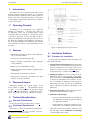
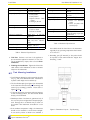
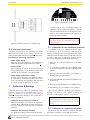
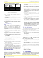
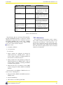
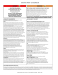
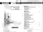
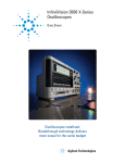
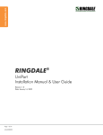
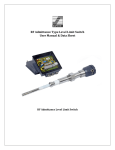
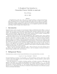
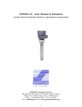
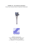
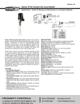
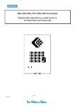
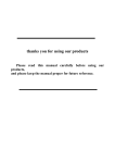
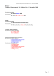
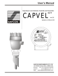
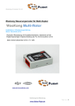
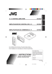
1
Coat-Endure
User Manual & Datasheet V 2.3
Contents
Revision History . . . . . . . . . . . . . . . .
1 Introduction . . . . . . . . . . . . . . . . .
2 Operating Principle . . . . . . . . . . . . .
3 Features . . . . . . . . . . . . . . . . . . .
4 Dimesional Layout . . . . . . . . . . . . . .
5 Technical Specifications . . . . . . . . . . .
5.1 Electrical Specifications . . . . . . . . .
5.2 Mechanical Specifications . . . . . . . .
6 Installation Guidlines . . . . . . . . . . . .
6.1 Procedure for Installation . . . . . . . .
6.2 Tank Mounting Installations . . . . . .
6.3 Electrical connections . . . . . . . . . .
7 Calibration & Settings . . . . . . . . . . . .
7.1 Calibration for non-conductive materials
7.2 Calibration for conductive materials . .
7.3 Sensitivity Adjustment . . . . . . . . .
7.4 COVER Delay . . . . . . . . . . . . . .
7.5 UNCOVER Delay . . . . . . . . . . . .
7.6 Fail-safe Selection . . . . . . . . . . . .
7.7 Error Indication . . . . . . . . . . . . .
7.8 Maintanence . . . . . . . . . . . . . . .
R
Sapcon Instruments Pvt.Ltd.
.
.
.
.
.
.
.
.
.
.
.
.
.
.
.
.
.
.
.
.
.
.
.
.
.
.
.
.
.
.
.
.
.
.
.
.
.
.
.
.
.
.
.
.
.
.
.
.
.
.
.
.
.
.
.
.
.
.
.
.
.
.
.
.
.
.
.
.
.
.
.
.
.
.
.
.
.
.
.
.
.
.
.
.
.
.
.
.
.
.
.
.
.
.
.
.
.
.
.
.
.
.
.
.
.
.
.
.
.
.
.
.
.
.
.
.
.
.
.
.
.
.
.
.
.
.
.
.
.
.
.
.
.
.
.
.
.
.
.
.
.
.
.
.
.
.
.
.
.
.
.
.
.
.
.
.
.
.
.
.
.
.
.
.
.
.
.
.
.
.
.
.
.
.
.
.
.
.
.
.
.
.
.
.
.
.
.
.
.
.
.
.
.
.
.
.
.
.
.
.
.
.
.
.
.
.
.
.
.
.
.
.
.
.
.
.
.
.
.
.
.
.
.
.
.
.
.
.
.
.
.
.
.
.
.
.
.
.
.
.
.
.
.
.
.
.
.
.
.
.
.
.
.
.
.
.
.
.
.
.
.
.
.
.
.
.
.
.
.
.
.
.
.
.
.
.
.
.
.
.
.
.
.
.
.
.
.
.
.
.
.
.
.
.
.
.
.
.
.
.
.
.
.
.
.
.
.
.
.
.
.
.
.
.
.
.
.
.
.
.
.
.
.
.
.
.
.
.
.
.
.
.
.
.
.
.
.
.
.
.
.
.
.
.
.
.
.
.
.
.
.
.
.
.
.
.
.
.
.
.
.
.
.
.
.
.
.
.
.
.
.
.
.
.
.
.
.
.
.
.
.
.
.
.
.
.
.
.
.
.
.
.
.
.
.
.
.
.
.
.
.
.
.
.
.
.
.
.
.
.
.
.
.
.
.
.
.
.
.
.
.
.
.
.
.
.
.
.
.
.
.
.
.
.
.
.
.
.
.
.
.
.
.
.
.
.
.
.
.
.
.
.
.
.
.
.
.
.
.
.
.
.
.
.
.
.
.
.
.
.
.
.
.
.
.
.
.
.
.
.
.
.
.
.
.
.
.
.
.
.
.
.
.
.
.
.
.
.
.
.
.
.
.
.
.
.
.
.
.
.
.
.
.
.
.
.
.
.
.
.
.
.
.
.
.
.
.
.
.
.
.
.
.
.
.
.
.
.
.
.
.
.
.
.
.
.
.
.
.
.
.
.
.
.
.
.
.
.
.
.
.
.
.
.
.
.
.
.
.
.
.
.
.
.
.
.
.
.
.
.
.
.
.
.
.
.
.
.
.
.
.
.
.
.
.
.
.
.
.
.
.
.
.
.
.
.
.
.
.
.
.
.
.
.
.
.
.
.
.
.
.
.
.
.
.
.
.
.
.
.
.
.
.
.
.
.
.
.
.
.
.
.
.
.
.
.
.
.
.
.
.
.
.
.
.
.
.
.
.
.
.
.
.
.
.
.
.
.
.
.
.
.
.
.
.
.
.
.
.
.
.
.
.
.
.
.
.
.
.
.
.
.
.
.
.
.
.
.
.
.
.
.
.
.
.
.
.
.
.
.
.
.
.
.
.
.
.
.
.
.
.
.
.
.
.
.
.
.
.
.
.
.
.
.
.
4
5
5
5
5
5
5
5
5
5
6
7
7
7
7
8
9
9
9
9
10
2
Coat-Endure
User Manual & Datasheet V 2.3
List of Figures
1
2
3
5
4
Dimensional Layout: Front View . .
Dimensional Layout - Top Mounting
Dimensional Layout - Side Mounting
Electrical Top panel . . . . . . . . .
Electrical Connections . . . . . . . .
R
Sapcon Instruments Pvt.Ltd.
List of Tables
.
.
.
.
.
.
.
.
.
.
.
.
.
.
.
5
6
7
7
8
2
3
4
5
Electrical Specifications .
Mechanical Specifcations
Switching Sensitivity . . .
Error Indications . . . . .
.
.
.
.
.
.
.
.
.
.
.
.
.
.
.
.
.
.
.
.
.
.
.
.
.
.
.
.
.
.
.
.
. 6
. 6
. 9
. 10
3
Coat-Endure
User Manual & Datasheet V 2.3
Revision History
Revision
1.0
1.1
1.2
2.0
2.1
2.2
2.3
Date
22 Jan,2014
22 Feb, 2014
25 Mar, 2014
20 Apr, 2014
25 Apr, 2014
10 May, 2014
23 April, 2015
Author(s)
MRK1
RND1
RND1
RND1
RND1
RND1
RND2
R
Sapcon Instruments Pvt.Ltd.
Description
created
Connection diagrams udpated
DIP switch position in diagrams updated
Header Correction
Version Control
Conductive Coat-Endure
Connection Diagrams updated as per Omni-box insert
4
Coat-Endure
1
User Manual & Datasheet V 2.3
Introduction
Coat-Endure is a microcontroller based compact coat
immune capacitance level limit switch. It is a compact
level switch which is suitable for sticky solids, pastes and
slurries. The device is specially suited for compact silos
and packaging machines where material has a tendency
to stick on the probe.
2
Operating Principle
Coat-Endure is an improvement over traditional
principle of admittance.
The ring type probe has
an alternating active and an inactive region, which
collectively help the controller to calculate the extent
of coating on the probe. In effect, the device is able to
identify the differential coating between the sense and
the shield by measuring their individual capacitances.
As the coating immunity is controlled by the on-board
microcontroller, the extent of coating immunity can be
set easily.
Figure 1: Dimensional Layout: Front View
3
Features
• Universal Power Supply of 18-55 V DC & 90-265 V
AC on the same terminal.
• Compact and customizable probe size.
• Passive shielding compensation with adjustable
coating immunity.
• Output options: Relay,PNP & Analog.
• High temperature probe suitable for applications up
to 200 Deg C.
• Self-diagnosis for probe and electronics.
• Popular with a wide range of materials: low-to-high
dielectric conductive materials
4
Dimesional Layout
Dimensional drawing for a probe length of 100
mm is shown in Figure 1. The dimensions shown
in Figure 1 can vary depending on the probe length
and the mounting arrangment. A dimensional drawing for your order can be made avaliable on request.
6
Installation Guidlines
6.1 Procedure for Installation
For quick and easy installation,follow the steps in the
order mentioned below:
1. Testing Electrical Connections: Before mounting
the device on the tank, understand and test the connections outside the tank for at least one piece. For
details on connections, refer to Figure 4 before connecting the device to outputs and power supply.
2. Mouting the Device: Correct mounting of the instrument is critical to the operation of the instrument. Please refer to Tank Mounting Installation
to mount the instrument in the tank/silo or hopper. Coat-Endure is designed to work properly in
metal-body tanks only, e.g. MS, SS or Aluminium
tanks. Performance in plastic tanks might not be
satisfactory.
3. Electrical Connections: Perform the electrical connections as mentioned earlier in Step 1.
4. Calibration and Settings:
5
Technical Specifications
5.1 Electrical Specifications
For electrical specfications please refer to Table 2.
5.2 Mechanical Specifications
Please refer to Table 3 for mechanical specifications.
1 Mininmum
switching time could vary depending on the dielectric constant of the application material
R
Sapcon Instruments Pvt.Ltd.
• For non-conductive materials, Coat-Endure can
be calibrated in an empty process tank without
the application material.
• If the application material is conductive, CoatEndure has to be calibrated with the material.
Time-delay and fail-safe selection should be done
afer this stage. Section Calibration and Settings
covers settings in more detail.
5
Coat-Endure
Parameter
Input Power Supply
Output (any one)
Switching
Switching Indication
Current Consumption
Fail safe
Delay Setting
Relay Rating
User Manual & Datasheet V 2.3
Value
18-55V DC/90-265V AC
(on same terminal)
• Relay SPDT
• Relay DPDT
• Open Collector - PNP
output
• Analog 8/16 mA
Single-point level switching
Bi-color LED
• Red for Alarm
• Green for Normal
50mA max. at 18V DC
with load
Field selectable (min. failsafe: low, max. fail-safe:
high)
Covered and Uncovered
Delays: 1-25 sec 1
6 Amps
Table 2: Electrical Specifications
5. Trial Run: Perform a trail run of the application
process with the application material. In case of errors or unsatisfactory output, refer to Section Error
Indications.
Parameter
Housing
Cable Entry
Operating Temprature
High Temperature
Operating Pressure
Mounting
Dimensions
Insulation
Value
Pressure Die Cast: aluminium
2 x 1/2“ BSP/NPT,
PG 13.5
0◦ C to +60◦ C (Electronics)
• 100◦ C for standard
probe
• 200◦ C for probe with
standoff pipe
Up to 10 bar
1” BSP / NPT Threaded
Flange mouting as per user
specification
Refer to GA Drawing
Part PTFE / Full PTFE
Table 3: Mechanical Specifcations
heat shield should be fitted above the instrument
especially if the operating temperature lies between
60◦ C and 80◦ C.
• Grounding part (SS material) of the probe should
be exposed at least 20mm inside the hopper after
threading / nozzle.
6. Finishing the Installation: Tighten the lid and the
cable entries on the instrument so that no moisture
seeps into the instrument.
6.2 Tank Mounting Installations
• Coat-Endure is designed to work in metal-body tanks
only, e.g. MS, SS or Aluminium tanks. Performance
in plastic tanks might not be satisfactory.
• The Coat-Endure probe (see figure 1)can be installed
in the vessel in both horizontal (side mounting) and
vertical (top mounting) positions. Please refer to
Figures 2 and 3.
• To prevent the ingress of moisture and water seepage
in side mounting position, the cable entries should
always point downwards.
• Weatherproofness of enclosure is guaranteed only if
the cover is in place and glands are adequately tightened. Damage due to accidental entry of water can
be avoided if the instrument is installed in a rain
shade.
• If the ambient temperature is high, the instrument
should not be installed to receive direct sunlight.
In case such a position of shade is not available, a
R
Sapcon Instruments Pvt.Ltd.
Figure 2: Dimensional Layout - Top Mounting
6
Coat-Endure
User Manual & Datasheet V 2.3
Coat-Endure
NORMAL
24-55
VDC
90-265
VAC
L
+
1
N
-2
E
3
OPEN
COVER
UNCOV
CALIBRATE
FAILSAFE
PNP
RELAY-1
NC
4
C
5
NO
6
+
-
7
8
ENTER
OUT RS485
9
10
V-2.0
ALARM
Figure 5: Electrical Top panel
acid based pastes, etc.), Coat-Endure needs to be
calibrated with the application material. This will
make the instrument specific to the application material i.e. if the application material is changed; calibration should be repeated.
Note: Calibration in air is specfic to the tank,
if the tank changes, the instrument needs to be
calibrated again.
Figure 3: Dimensional Layout - Side Mounting
7.1 Calibration for non-conductive materials
6.3 Electrical connections
Electrical connections for the instrument will change
with the models. Please refer to Figure 4 and the precautions mentioned below before connecting the device.
Precautions for connecting Coat-Endure
• Power Supply Rating
Make sure the power supplied to the instrument is
within the specified range mentioned in Table 2.
• Connect Earth
When supplying AC power, please make sure that
the grounding screw on the housing and the earth
terminal are all connected to the plant’s earth.
• Power Supply Fluctuations & Noise
External noise or flucating power supplies could affect performace and shorten the life of the instrument. Use external line suppressors and fuse wires
to contain the risk of damage to the circuit.
Coat-Endure needs to be calibrated inside the empty
process tank (i.e only air, no material). Calibrating the instrument outside the tank can cause malfunctions. Once
calibrated inside the empty tank, Coat-Endure can operate with a wide range of application materials without
the need of changing its default senstivity settings.
1. Make sure that all DIP switches are in the Open
position.
2. To start with the calibration, set the CALIB switch
to close position.(Close is opposite of OPEN for DIP
switch)
3. Make sure that the Status LED is not blinking. A
blinking LED here indicates Error.
4. Then press ENTER, the Status LED will blink once
in RED color.
5. Now set the CALIB switch back to OPEN position.
7
Calibration & Settings
The DIP switches for calibration and settings can be
accesed by opening the top aluminium cover. Refer to
Figure 5 for information on DIP swtiches Procedure for
calibration Coat-Endure depends on the conductivity of
the application material:
6. Air calibration for Coat-Endure is now complete.
Now, test the calibration by filling in the material or
draining it out from the tank. Repeat the filling and
draining to confirm proper operation of the device.
Note: For certain application materials, CoatEndure might need an adjustment to its settings.
Refer to Section Sensitivity Adjustment for more
details.
• Calibration for non-conductive materials
Calibration should be done without the application
material. Once calibrated in the empty tank, the device can be used with a wide range of non-conductive
materials.
7.2 Calibration for conductive materials
• Calibration for conductive materials
For applications using conductive materials (water,
Fill the tank with the application material such that
the probe is completely covered with the material.
R
Sapcon Instruments Pvt.Ltd.
7
Coat-Endure
24 TO 55VDC
Relay Contacts (Potential Free)
Pin
No.
Line
(+)
1
Neutral
(-)
2
Earth
Earth
3
Alarm position for covd. in high failsafe
Alarm position for uncov. in low failsafe
Status LED
90 TO 265VAC
User Manual & Datasheet V 2.3
RED
No.
6
ALARM
Pole(C)
5
GREEN NORMAL
High failsafe : FAILSAFE switch open
Low failsafe : FAILSAFE switch closed
(a) Powering the device
NC
4
(b) Relay Connections
Pin
PNP Output (Internally Isolated)
Condition PNP
Pin
NO
Alarm
OFF
RED
Normal
ON
GREEN
Above applies
irrespective of falisafe
No.
-
LED
8
9
PNP- collector output
can drive loads upto
90mA at 24V.
(c) PNP(isolated) output connections
Figure 4: Electrical Connections
Connection Diagrams for different outputs are mentioned above. As per your model, select a connection diagram and
connect the device.
1. Make sure that all DIP switches are in the Open
position.
2. To start with the calibration, set the CALIB and
COVER switches to close position.(Close is opposite
of OPEN for DIP switch)
sensitivity is set to 3 to suit a wide range of materials.
Traverse the following steps to set the sensitivity of CoatEndure 1. Select a sensitivity value for the instrument as per
Table 4.
3. Make sure that the Status LED is not blinking, a
blinking LED here indicates Error.
2. Set the CALIB switch to CLOSE position.
4. Then press ENTER, the Status LED will blink once
in RED color.
4. PRESS and HOLD the ENTER key, the status LED
will start blinking.
5. Now set the CALIB and COVER switch back to
OPEN position.
5. The first blink leaves the sensitivity value unchanged.
6. Calibration for Coat-Endure is now complete.
6. Start counting from the next blink upto the selected
sensitivity value.
Now, test the calibration by filling in the material or
draining it out from the tank. Repeat the filling and
draining to confirm proper operation of the device.
Note: For certain conductive application materials, Coat-Endure might need an adjustment to
its settings. Refer to Section Sentivity Adjustment for more details.
7.3 Sensitivity Adjustment
The instrument has 5-point sensitivity level to suit a
wider range of application materials. Sensitivity value
should be decided with respect to the dielectric constant
and coating thickness of the application material. Refer
to Table 4 for selecting a suitable value. By default, the
R
Sapcon Instruments Pvt.Ltd.
3. Also switch the UNCV switch to CLOSE position.
7. Set the CALIB and UNCV switches back to OPEN
position.
8. Check operation of Coat-Endure by filling in and
draining out the material.
9. If the instrument does not switch when covered fully
with the material, try again with a higher value of
sensitivity.
10. If the instrument switches when covered fully with
the material, but does not switch back to normal
state when uncovered, try again with a lower sensitivity value.
Factory Reset To reset time delays and sensitivity values
to default values, follow the following steps:
8
Coat-Endure
User Manual & Datasheet V 2.3
Application Material Properties
Dielectric
Const.
High
Low
High
Low
Coating
Thickness
High
High
Low
Low
Sensitivity
Value
1−3
3 − 5(default)
1−2
5
Table 4: Switching Sensitivity
1. Set the CALIB, COV and UNCOV switches to
CLOSE position
2. PRESS and HOLD the ENTER key until the status
LED blinks.
3. Switch the CALIB, COV and UNCOV switches back
to OPEN position.
4. This will set the time delay to 0 and the sensitivity
level to 3.
7.4 COVER Delay
When material covers the Coat-Endure probe, the
changeover of the output can be delayed by a predetermined time. This time is called COVER Delay. Follow the steps mentioned below to set the COVER delay
to 2 seconds.
1. To set the uncover delay, set the UNCOV switch to
close position.
2. Make sure that the status LED is not blinking for
Error. Then press ENTER and keep it pressed.
3. The Status LED will blink. Count the number of
blinks of the LED.To Set a delay pf two seconds,
two Blinks will be required. After two blinks, release
the ENTER key.
4. Uncover Delay is entered, but not saved. To save
and test the uncover delay, set the cover switch back
to open position.
5. To test, dip the probe into the material until the
switching point is achieved.
6. Coat-Endure will start blinking RED if the switch
point is reached. It will blink for the number of
seconds for which the uncover delay is set.
7. Now, remove the probe from the material until the
other switch point is acheived. The Status LED will
start blinking GREEN to indicate that the uncover
switch point is reached. It will blink for the number
of seconds for which the uncover delay is set.
7.6 Fail-safe Selection
1. To set the cover delay, set the COVER switch to
close position.
In Coat-Endure, fail-safe is applied as soon as its DIP
switch is set for the required fail-safe operation.
When fail-safe is set to HIGH (default) - Fail-safe
switch is OPEN :
2. Make sure that the Status LED is not blinking for
Error.
1. Relay ON - When not in contact with the material,
LED turns RED.
3. Then press ENTER and keep it pressed. The Status
LED will Blink.
2. Relay OFF - When in contact with the material, LED
turns GREEN.
4. Count the blinks of the LED. To Set a delay two seconds, two blinks will be required. After two blinks,
release the ENTER key.
When fail-safe is set to LOW : The operation is reversed - Fail-safe switch is CLOSED.
5. Delay is entered, but not saved.
6. To save and test the cover delay, set the cover switch
back to open position.
7. To test, dip the probe into the material until the
switching point is reached.
Coat-Endure will start blinking RED if the switch point
is reached. It will blink for the number of seconds for
which the cover delay is set. 1 Blink is equal to 1 second
during switching. A maximum of 25 seconds can be set.
7.5 UNCOVER Delay
When the material uncovers the Coat-Endure probe,
the changeover of the output can be delayed by a predetermined time. This time is called the UNCOVER Delay. Follow the steps mentioned below to set the UNCOVER delay to 2 seconds.
R
Sapcon Instruments Pvt.Ltd.
1. Relay ON - When in contact with the material, LED
turns RED.
2. Relay OFF - When not in contact with the material,
LED turns GREEN.
Irrespective of the fail-safe value, the color of the blinking LED when the cover and uncover delays are SET will
be:
• RED: Cover Delay
• GREEN: Uncover Delay
7.7 Error Indication
In Coat Endure, errors are indicative of operators mishandling of the instrument. These are provided to ensure
proper setting and protection of the instrument.
9
Coat-Endure
User Manual & Datasheet V 2.3
LED Error Indication
RED-GREEN Blinking
Description
Troubleshooting
Calibration Error
RED blinking
Probe short-circuit
GREEN Blinking
Probe Open
3 times GREEN
Blinking & one Red
Blink
3 times RED Blinking & one GREEN
Blink
Illegal Key combination
Recalibrate the instrument,
make sure that the probe
is calibrated in an empty
metal-body tank.
Moisture deposition in the
probe connector. Clean the
connector and use the instrument.
Remove the electronic insert from the housing and
check the cable connections
of the probe.
Switch all DIP switches to
open position. Use only legal combination of keys.
Contact the Customer Support department at Sapcon.
Circuit Error
Table 5: Error Indications
Error Indication: On error, the Status LED starts blinking RED and GREEN alternately at a faster rate. Normal
LED blinks are always at the rate of 1 blink per second, in
either RED or GREEN colour. In some cases, a GREEN
or a RED blinking could indicate an error. Refer to Table
5 for a list of errors and their indication.
Nature of error:
1. Incomplete calibration
7.8 Maintanence
The electronics of this instrument needs no maintenance. When cleaning and checking the vessel, free the
tuning probe from deposits. If the material has a tendency to form a hard sticky deposit, then the instrument
must be checked more often. Make sure that the cable
ducts and the lid are tightly sealed so that no moisture
seeps into the instrument.
2. Low capacitance
To avoid errors:
1. Always complete the calibration by putting the
CALIB switch back to OPEN position. This can
be done within 2 minutes of releasing ENTER for
the last time for calibration purpose.
2. Always complete the delay settings by putting the
DELAY switches back to OPEN position. This can
be done within 2 minutes of releasing the ENTER
for DELAY setting purpose.
3. Make sure that only 1 one switch is at the CLOSE
position amongst the CALIB, COVER and UNCOV
switches .
Fail-safe switch can be OPEN or CLOSE and is not a
source of error. Resetting Error:
1. Bring the CALIB, COVER and UNCOV switches to
OPEN position.
2. Press the ENTER key.
3. LED alternate color blinking will STOP.
R
Sapcon Instruments Pvt.Ltd.
10