1
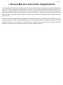
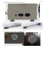
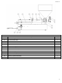
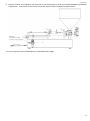
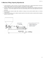
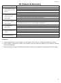
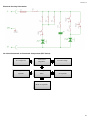
Revision: A USER MANUAL FILLING MACHINES SINGLE HEAD 60, 125, 1000, 5000 mL 1 Revision: A Table of Contents I. General Machine Information & Applications 3 II. Machine Features 4-6 III. Parts List 7-11 IV. Technical Data 12 V. Setup & Operation 13-19 a. Machine Initial Setup 13-16 b. Machine Idle Tuning 17 c. Machine Filling Capacity Adjustments 18 d. Machine Operation 19 VI. Service & Maintenance 20 VII. Failure & Recovery 21-23 2 Revision: A I. General Machine Information & Applications The semi-automatic pneumatic series filling machines are the latest of advanced designs that offer precise filling options ideal for the home, restaurant, industrial shop, or any other setting requiring containment of liquid or paste, “wet” products. A gravity-fed design that utilizes vacuum pressure with instant “drip-free” cut-off, allows the machine to operate efficiently and avoid unnecessary waste and power consumption. With the majority of the components made from high quality, food-grade stainless steel, rest assured that this machine will reliably dispense sanitary product for years to come. The table-top machine design allows for portable use as a single entity or easy configuration in an assembly line, which will prove extremely versatile in the pharmaceutical, food, and chemical industries. Examples of product that can be dispensed include but are not limited to: sweet chili sauce, salsa, BBQ sauce, tomato sauce, cooking oil, creamed potatoes, mineral water, juice, shampoo, lotions, body scrubs, detergent, and so on. 3 Revision: A II. Machine Features Universal outputting mouth dispense head for optimal product flow: applicable to 60, 125, & 1000mL models, actual nozzle may vary by machine size Bracket keyway to elimate slippage between drive cylinder and rotating mechanical valve Standard english and metric food-grade Viton rubber seals, found at most USA industrial suppliers mechanical valve U-cup seal made of durable food-grade 90A Hard Nitrile rubber UL reocgnized foot pedal, power cord, and general electrical wiring 4 Revision: A Upgraded plugs and sockets for foot pedal and power cord Dual unit pressure gauge reading in both kg/cm3 and psi 5 Revision: A Dual unit filling capacity label in both oz and mL Assembly kit containing additional hardware and tools for machine setup and maintenance 6 Revision: A III. Parts List Machine Parts List, Front View Item No. Description Qty. 1 Machine Hopper 1 2 Straining Ring Clamp Assembly, Medium 1 3 Air Cylinder, AirTAC SDA25X30 (60, 125, & 1000mL), & SDA50X50 (5000mL) 1 4 Outputting Mouth 1 5 Straining Ring Clamp Assembly, Small 1 6 Outputting Mouth Nozzle 1 7 Selector Valve 1 8 Straining Ring Clamp Assembly, Medium (60 & 125mL), Large (1000mL), or X-Large (5000mL) 1 9 Machine Base 1 10 Machine Base Leg 1 11 Reversing Cylinder Board 1 12 Main Cylinder Frontal Board 1 13 Machine Control Button, Clean (Green) 1 14 Machine Control Button, Automatic/Manual (Green) 1 15 Machine Control Button, Stand by (Red) 1 16 Pressure Gauge, PSI 1 17 Machine Power Cord 1 18 Machine Foot Pedal 1 19 Adjustor Hand Wheel 1 20 Main Cylinder Back Board 1 21 AdjustableThrottle Valve, Reverse Stroke for AirTAC SC63X150-S, SC63X270-S, & SC80X270-S 1 22 Adjustable Inductive Switch 1 23 Main Air Cylinder, AirTAC SC63X150-S (60 & 125mL) , SC63X270-S (1000mL), SC80X270-S (5000mL) 1 24 Fixed Inductive Switch 2 25 AdjustableThrottle Valve, Forward Stroke for AirTAC SC63X150-S, SC63X270-S, & SC80X270-S 1 26 Piston Cylinder 1 27 Piston Cylinder Board 1 7 Revision: A Machine Parts List, Rear View Item No. Description Qty. 28 Air Pressure Regulator, AirTAC AFR2000 1 29 Air Lockout Check Valve 1 30 Air Inlet Connection Port Fitting 1 31 Filler Indicator Mark Index 1 32 Adjustable Screw Rod 1 33 Handle, Reversing Cylinder Board 1 34 Adjustable Throttle Valve, Reverse Stroke for AirTAC MAL32X50-CA 1 35 Adjustable Throttle Valve, Forward Stroke for AirTAC MAL32X50-CA 1 36 Handle, Piston Cylinder Board 1 37 Air Connection Fitting Port, Reverse Stroke for AirTAX SDA25X30 1 38 Adjustable Throttle Valve, Forward Stroke for AirTAC SDA25X30 1 39 Reversing Cylinder Staff Bracket 1 40 Selector Valve Base Mount 1 8 Revision: A Machine Parts List, Right Side View Item No. Description Qty. 41 Socket, Machine Foot Pedal 1 42 Socket, Machine Power Cord 1 43 Machine Fuse Holder and Fuse 1 9 Revision: A Machine Parts List, Rubber Seals Item No. Description Seal Type 44 Outputting Mouth O-Ring 45 Leakproof Cylinder Shaft O-Ring Seal Standard AS568A-207 AS568A-214 Material Viton Viton Machine (mL) 60, 125, 1000 5000 60, 125, 1000 5000 Qty. 1 1 60 46 Outputting Mouth Nozzle O-Ring Viton AS568A-218 125 1 1000 5000 47 Small Sealing Ring Gasket 48 Selector Valve Cover O-Ring Tri-Clamp 1-1/2” Metric 41 ID x 3 W Viton Viton All 60, 125, 1000 5000 1 2 60 49 Piston O-Ring Viton AS568A-332 125 2 1000 5000 Medium Sealing Ring 50 Large Sealing Ring Tri-Clamp 2-1/2” Gasket X-Large Sealing Ring Tri-Clamp 3” 60, 125 Viton Tri-Clamp 4” 1000 1 5000 51 Selector Valve Core U-Cup 25ID x 33OD x 5H 90A Nitrile All 1 52 Medium Sealing Ring Gasket Tri-Clamp 2-1/2” Viton All 1 10 Revision: A Machine Parts List, Assembly Kit Item No. Description Qty. 53 Double Open End Wrench, 8mm & 10mm 1 54 Double Open End Wrench, 12mm & 14mm 1 55 Filling Machine User Manual 1 56 Assembly Kit Poly Bag 1 57 Medium Sealing Ring 1 58 Cross Screw Driver (Phillips Head) 1 59 Slotted Screw Driver (Flat Head) 1 60 Replacement Machine Fuse 1 61 Adjustor Hand Wheel Handle Screw 1 62 Adjustor Hand Wheel Handle 1 63 Machine Power Cord 1 64 Machine Foot Pedal 1 65 3mm Hex Key Wrench 1 66 4mm Hex Key Wrench 1 67 5mm Hex Key Wrench 1 68 6mm Hex Key Wrench 1 69 8mm Hex Key Wrench 1 11 Revision: A IV. Technical Data PPF-250 PPF-250T PPF-500 PPF-500T Voltage (V/Hz) AC 220/50 or 110/60 Power (W) 20 Air Pressure (MPa/psi) 0.4-0.6/58-87 Filling Range (ml) 50-250 50-250 100-500 100-500 Filling Frequency (cyl/min) 10-18 Filling Accuracy ≤1% PPF-1000 PPF-1000T 100-1000 100-1000 External Dimensions (LxWxH) (cm) 90x50x105 77x25x78 100x50x105 88x25x77 110x50x105 101x25x77 Net Weight (Kg) 30 25.5 35 27 40 32 12 Revision: A V. Setup & Operation A. Machine Initial Setup 1. Upon receipt of your new machine, please unpack the machine and hopper to ensure all contents are included and that there are no evidential signs of damage to your product. If you feel a component is missing or damaged, please contact your supplier for immediate assistance. 2. Locate the accessory kit and ensure all components listed in the parts list section of this document, are included. 3. Place machine on stable working table check to see if any components are noticeably loose. Use supplied hex keys and screw drivers to tighten down loose components as necessary. 4. Check to ensure the machine ground line is properly connected as shown below. 13 Revision: A 5. Locate machine fuse holder and ensure fuse is installed as shown below. 6. Locate medium sealing ring that came with the accessory kit. Remove clamp on top of selector valve and place medium sealing ring on top of flange. Install hopper such that the medium sealing ring forms a flush sealing surface between hopper and selector valve. Clamp hopper to selector valve. 14 Revision: A 7. Install adjustor hand wheel handle with supplied screw drivers as shown below. 8. Plug power cord and foot pedal into correct machine socket as shown below. 15 Revision: A 9. Remove all dust, dirt, impurities, etc from inlet air connection port to avoid any possible damage to pneumatic components. Connect air line to inlet air connection port on back of machine as shown below. 10. Connect power cord to a 220V/50Hz or 110V/60Hz power supply. 16 Revision: A B. Machine Idle Tuning 1. Adjust the air pressure regulator (as shown below) to reach air pressure of 0.4-0.6 MPa (58-87 psi), which is optimal for continual machine use. 2. Press the optional Automatic/Manual button to engage manual mode and run several filling cycles i. Note: Place a bucket or alternate contain under the outputting mouth nozzle during this step 3. Filling speed can be increased or decreased by the user to optimize production efficiency. It is generally recommended to increase filling speed when the piston cylinder is in vacuum or suction mode and to slow down when the piston cylinder discharge or filling mode. Please refer to the following for fine-tuning adjustments: i. Loosen the locking thumb nut on throttle valve ii. Turn throttle valve counter clock-wise to increase speed or clock-wise to decrease speed iii. Fasten locking thumb nut iv. Usually adjusting the throttle valves on the main cylinder is all that is needed to control filling speeds 17 Revision: A C. Machine Filling Capacity Adjustments 1. Coarse adjustment: loosen set screw on the filler indicator bracket and turn adjustor hand wheel to move the inductive switch position to the correct fill capacity—this adjusts your filling capacity. 2. Precision adjustment: Fine-tune filling capacity for possible errors by adjusting fill amount against actual amount dispensed. Lock the filler adjustor lock screw once desired filling amount and actual dispensed amount are equivalent. 3. Do not move the inductive switch while machine is running, this may cause machine failure or incorrect measurements. 4. If the inductive switch is moved, adjust the position again until the machine works as desired and then properly fasten the inductive switch. 18 Revision: A D. Machine Operation 1. After machine setup, idle tuning, and adjustments are complete the machine is now ready for use. Please use the following control buttons according to your production needs to operate the machine. Clean (Green Button) – allows user to clean out the system Automatic/Manual (Green Button) – allows user to operate in manual mode (foot pedal) or automatic mode (without foot pedal) Stand-by (Red Button) – machine shutoff 19 Revision: A VI. Service & Maintenance 1. Clean the air circuitry components thoroughly and often to prevent dust, dirt or any other impurities from affecting the pneumatic performance of the machine. 2. Keep foreign and/or sharp objects away from machine to prevent surfaces and components from being scratched or furthered damaged, which could affect machine measurement calibrations. It is recommended that all product be appropriately filtered prior to processing through machine. 3. To prolong the life of the machine and its pneumatic components, it is highly recommended to us a clean, filtered air supply for machine operation. 4. DO NOT operate machine without liquid or paste “wet product” in the hopper, or without product cycling through the machine. Failure to do so can result in damage to all internal rubber seals (O-rings and Gaskets) 5. DO NOT operate machine with products that are not in the liquid or paste form (i.e. hard materials, beaded materials, pellets, etc). Failure to do so may result in permanent damage to machine. 6. To avoid corrosion, contamination, or further damage to machine and its surfaces, it is recommended to regularly clean all components thoroughly. Depending on your exact process, use FDA or industry approved stainless steel cleaner for stainless steel components, and FDA or industry approved cleaner for non-stainless steel components. Clean components with a lint-free cloth. 7. If machine is to be without use for a long period of time, place it in a dry location, remove and clean all components thoroughly, and cover the machine. 20 Revision: A VII. Failure & Recovery Failure Mode 1. Pilot lamp doesn't shines and machine cannot start running. 2. Cylinder moves slowly and reciprocating motion shows fatigue 3. Power and air supply are connected, but machine will not operate 4. Inconsistent Filling Measurement 5. Blocked outputting mouth nozzle 6. Leaking Components Recovery Mode 1. Check and ensure power supply is properly connected 2. Check and ensure all air tubes are properly connected 3. Check and ensure foot pedal is properly connected 4. Check and ensure machine fuse is properly installed 1. Low air pressure. Please adjust the air pressure regulator 2. Mechanical interference, ensure all components are assembled correctly 3. Air cylinder could be damaged, contact supplier for replacement 4. Damaged electromagnetic valve, contact supplier for replacement 1. Adjust the position of inductive switch(es) 2. Damaged electromagnetic valve, contact supplier for replacement 1. Damaged piston, piston 2. Filling speed is too fast, adjust and slow down the filling speed 3. Worn electromagnetic valve or inductive switch, contact supplier for replacement 1. Mechanical chucking 2. Damaged leakage proof cylinder, change the cylinder 3. Air pipeline is wrong connected 1. Damaged leakage proof cylinder 2. Damaged gasket, change the leakage proof piston gasket. cylinder, or air cylinder, contact supplier for replacement Provisions: 1. Contact a professional or your supplier if you are unable to clean, service, or otherwise maintain the machine 2. Never change or swap the air tubes on the machine, this will cause the machine to not operate or become permanently damaged 3. Before cleaning, servicing or otherwise maintaining the machine, stop operation and unplug power and air supply 21 Revision: A Electrical Circuitry Schematics: Air Circuit Schematic for Pneumatic Components (PPF Series): Air Compressor Air Pressure Regulator Pressure Gauge Outputting Mouth Air Cylinder Electromagnetic Valve Selector Valve Air Cylinder Main Air Cylinder 22 Revision: A Air Circuit Schematic for Pneumatic Components (LPF Series): Air Compressor Air Pressure Regulator Outputting Mouth Air Cylinder Electromagnetic Valve Pressure Gauge Main Air Cylinder 23