Transcript
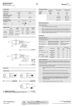
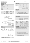
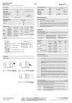
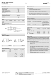
SMRR 7600 USER MANUAL
SpaceMaster Series
tel
EN
Photoelectric retro-reflective sensors
Product Data
Mounting & Alignment
Electrical Data
Supply Voltage
Voltage ripple
Reverse polarity protected
Short circuit protected
Current consumption
Max. output load
Mounting & Alignment
10-30 V dc
+/- 15%
Yes
Yes
20 mA
120 mA / 30 V dc
Environmental Data
Temperature, operation
Sealing class
-20 to +60 ºC
IP 67
1
Position the sensor pointing at a retro-reflector.
2
Align by moving sensor horizontally and vertically until the output status changes when
aiming at retro-reflector and when no object is present (refer to Output Logic table).
3
Fasten the sensor securely using the enclosed locking nuts and/or a mounting bracket.
Avoid acute angles on cable close to sensor.
Adjustments
Approvals
Output Mode Selection
Available Models
Retro
reflective
Model
Supply
Voltage
Output
Output
Mode
Sensing
Range
SMRR 7600
10-30 V dc
NPN / PNP
Light/dark
0-3 m*
* Note: Measured against Ø85 mm retro-reflector.
The output mode can be selected via an integral light/dark switch. Refer to Output Logic table
for output mode reference.
Light Operated (N.C.)
Enables the output to be inactive
when there is an object present.
Turn switch to full clockwise
position
Dark Operated (N.O.)
Enables the output to be active
when there is an object present.
Turn switch to full counter
clockwise position
Illustration
Output Logic
Detection
Object present
Object absent
Output mode
Output status
Yellow LED
Dark operated (N.O.)
Closed
On
Light operated (N.C.)
Open
Off
Light operated (N.C.)
Closed
On
Dark operated (N.O.)
Open
Off
Sensitivity Adjustment
Connection
Maximum sensitivity can be used for most applications and is advised for applications with
contaminated environments. Increase the sensitivity to maximum by turning the potentiometer
to full clockwise position.
Wiring Diagrams
Sensitivity adjustment may be required in applications where objects to be detected are small
or translucent. Proceed with the following steps:
SMRR 7600
Load as NPN
Connection Wires/Pins
Cable
Supply + / Brown
Supply - / Blue
Output / White
Output / Black
SMRR 7600
Load as PNP
4 pin, M8 plug
Pin 1
Pin 3
Pin 2
Pin 4
4 pin, M12 plug
Pin 1
Pin 3
Pin 2
Pin 4
Sensor plug
Sensor plug
1
Start with the sensitivity at maximum by turning the potentiometer to full clockwise
position.
2
Select target object with smallest dimensions and most translucent surface.
3
Place target object between the sensor and retro-reflector. If the output status
changes, adjustment is not required. If the output has not changed proceed to step 4
4
Decrease the sensitivity by turning the potentiometer counter clockwise until the output
changes. If the output has not changed, attempt to move the sensor and retro-reflector
further apart or angle the sensor/retro-reflector. Then repeat procedure from step 1.
5
Remove target object. Check the output status has changed.
-
Website: www.telcosensors.com
E-Mail: [email protected]
Made in Denmark
!
Warning
This product is not a safety system and must not be used as such.
It is not designed for personnel safety applications, and must not be used
as a stand alone personnel safety system.
V 1.0 Part Number: 0666220627
January 2011 edition
Telco A/S reserves the right to make changes without prior notice