1
BASIC INFORMATION ON THE
SURGICAL PROCEDURES
Straumann® Dental Implant System
122461_15X.754.indd a
17.9.2007 9:46:59 Uhr
Straumann is industrial partner of the ITI (International Team for Implantology)
in the areas of research, development and education.
122461_15X.754.indd b
17.9.2007 9:47:03 Uhr
CONTENTS
About this guide
2
1. The Straumann® Dental Implant System
1.1 Overview
1.2 Implant lines
1.2.1 Straumann® Standard Implant
1.2.2 Straumann® Standard Plus Implant
1.2.3 Straumann® Tapered Effect Implant
1.2.4 Straumann® Bone Level Implant
1.3 Implant-abutment connections
1.3.1 Straumann® synOcta
Morse taper connection
1.3.2 Straumann® Narrow Neck Connection
1.3.3 Straumann® Bone Level CrossFit™
Connection
1.4 Surfaces
1.4.1 Straumann® SLActive
1.4.2 Straumann® SLA
3
3
6
6
6
6
6
7
2. Indications and Contraindications
2.1 Indications
2.1.1 Specific indications for small diameter
(Ø 3,3 mm) implants
2.1.2 Specific indications for Straumann®
implants with a length of 6 mm
2.2 Contraindications
2.2.1 Relative contraindications
2.2.2 Local contraindications
2.3 Implant specific indications
10
10
3. Preoperative Planning
3.1 Implant position
3.1.1 Mesiodistal implant position
3.1.1.1 Examples for single tooth gaps
3.1.1.2 Examples of multiple tooth gaps
3.1.2 Orofacial implant position
3.1.3 Coronoapical implant position
3.2 Planning aids
3.2.1 Mesiodistal and orofacial space
requirements
3.2.1.1 Diagnostic T for Straumann® Standard,
Standard Plus, and Tapered Effect implants
3.2.1.2 Straumann® Implant Distance Indicator
3.2.2 Determining the vertical bone availability
3.2.2.1 X-ray reference sphere
3.2.2.2 X-ray templates
3.2.3 Surgical drill template
3.2.3.1 Vacuum-formed drill template
3.2.3.2 Thermoplastic drill template
15
15
16
17
19
20
21
23
122461_15X.754.indd Abs1:1
7
7
8
9
9
9
10
10
10
10
10
11
4. Surgical Procedures
4.1 Implant bed preparation
4.1.1 Basic implant bed preparation
4.1.2 Fine implant bed preparation
4.1.3 Examples for fine implant bed preparation
4.2 Opening the implant package
4.3 Placing the implant
4.4 Soft tissue management
4.4.1 Submucosal healing
4.4.2 Transmucosal healing
30
30
31
35
38
42
44
50
50
53
5. Healing Phase
5.1 Healing phase duration
5.2 Straumann® SLActive and SLA in comparison
57
57
57
6. Additional Information on Instruments
6.1 Surgical instruments
6.1.1 Depth marks on Straumann® instruments
6.1.2 Single-patient pilot and twist drills
6.1.3 Straumann® Drill Stop
6.1.4 Straumann® Surgical Cassette
6.1.5 Ratchet
6.1.6 Holding key
6.1.7 SCS screwdrivers
6.2 Osteotomes
6.2.1 Instrument set for bone condensation
6.2.2 Instrument set for transalveolar sinus floor
elevation
6.2.3 Depth stops for osteotomes
6.3 Cleaning and care of instruments
58
58
58
59
59
61
63
64
64
65
65
7. Appendix
7.1 Labeling and color coding of the
Straumann® Dental Implant System
7.2 Related documentation
7.3 Important notes
68
68
70
72
8.
73
Index
65
65
66
23
23
24
25
25
26
28
28
29
17.9.2007 9:47:03 Uhr
ABOUT THIS GUIDE
Basic Information on the Surgical Procedures for the Straumann® Dental Implant System provides dental practitioners and related specialists with the essential steps regarding surgical treatment, planning, and procedure.
The manual is divided into the following main parts:
p The Straumann® Dental Implant System
p Indications and Contraindications
p Preoperative Planning
p Surgical Procedures
p Healing Phase
p Additional Information on Instruments
p Appendix
p Index
For further information regarding the Straumann® Dental Implant System, visit
our comprehensive website at www.straumann.com.
2
122461_15X.754.indd Abs1:2
17.9.2007 9:47:04 Uhr
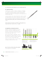
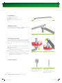
1. THE STRAUMANN ® DENTAL IMPLANT SYSTEM
1.1 Overview
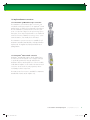
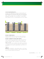
The Straumann® Dental Implant System offers four implant
lines with diverse body and neck designs, ranging from
the classic soft tissue level to the bone level implant. All
implants can be placed with one surgical kit while using
very similar surgical procedures.
Straumann® implants have been extensively researched.
Their optimized design, called Bone Control Design™,
S
SP
is based on the five key biological principles in implant
dentistry: osseoconductivity of the implant surface, control
of the microgap, biomechanical implant design, biological
distance, and the location of the surface margin.
With the Bone Control Design™, Straumann® implants
help to achieve optimal preservation of crestal bone and
soft tissue stability.
TE
2,8 mm
BL
1,8 mm
Straumann®
Standard
Implant (S)
Straumann®
Standard Plus
Implant (SP)
Straumann®
Tapered Effect
Implant (TE)
Straumann®
Bone Level
Implant (BL)
The classic soft tissue level implant
The implant for
flexible placement
The implant for
immediate placement
Straumann expertise applied at
bone level
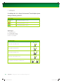
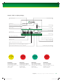
Straumann® dental implants are available in three endosteal diameters: Ø 3,3 mm, Ø 4,1 mm, and Ø 4,8 mm.
A unified color code simplifies identification of instruments and implants.
Color coding
yellow
Endosteal implant diameter 3,3 mm
red
Endosteal implant diameter 4,1 mm
green
Endosteal implant diameter 4,8 mm
1. The Straumann ® Dental Implant System
122461_15X.754.indd Abs1:3
1.1 Overview
3
17.9.2007 9:47:04 Uhr
Implant
overview
Straumann ® Standard Implant
Straumann ® Standard Plus
S Ø 4.1 RN
S Ø 4.8 RN
S Ø 4.8 WN
SP Ø 3.3 NN
SP Ø 3.3 RN
SP Ø 4.1 RN
Neck
diameter
Ø 4,8 mm
Ø 4,8 mm
Ø 4,8 mm
Ø 6,5 mm
Ø 3,5 mm
Ø 4,8 mm
Ø 4,8 mm
Endosteal
diameter
Ø 3,3 mm
Ø 4,1 mm
Ø 4,8 mm
Ø 4,8 mm
Ø 3,3 mm
Ø 3,3 mm
Ø 4,1 mm
033.030S
033.230S
033.630S
SP
2,8 mm
S Ø 3.3 RN
SLActive
6 mm
8 mm
033.131S
033.031S
033.231S
033.631S
033.951S
033.151S
033.051S
10 mm
033.132S
033.032S
033.232S
033.632S
033.952S
033.152S
033.052S
12 mm
033.133S
033.033S
033.233S
033.633S
033.953S
033.153S
033.053S
14 mm
033.134S
033.034S
033.234S
033.954S
033.154S
033.054S
16 mm
033.135S
033.035S
SLA®
6 mm
043.030S
043.230S
043.630S
043.050S
8 mm
043.131S
043.031S
043.231S
043.631S
042.930S
043.151S
043.051S
10 mm
043.132S
043.032S
043.232S
043.632S
042.931S
043.152S
043.052S
12 mm
043.133S
043.033S
043.233S
043.633S
042.932S
043.153S
043.053S
14 mm
043.134S
043.034S
043.234S
042.933S
043.154S
043.054S
16 mm
043.135S
043.035S
RN
RN
NN
RN
RN
Connection
Prosthetic
restoration
components
4
033.050S
RN synOcta
®
RN Solid Abutment
RN synOcta
RN synOcta
WN
®
WN synOcta
®
WN Solid Abutment
NN
RN synOcta
®
RN Solid Abutment
RN synOcta ®
RN
RN Solid Abutment
RN
RN Solid Abutment
RN Solid Abutment
Retentive Anchor
Retentive Anchor
Retentive Anchor
Ret
steco ®
steco ®
steco ®
ste
Titanmagnetics ®
Titanmagnetics ®
Titanmagnetics ®
Tit
LOCATOR®
LOCATOR®
LOCATOR®
LOC
1. The Straumann ® Dental Implant System
122461_15X.754.indd Abs1:4
RN
®
1.1 Overview
17.9.2007 9:47:06 Uhr
Plus Implant
Straumann ® Tapered Effect Implant
TE Ø 3.3 RN
TE Ø 4.1 RN
TE Ø 4.8 WN
BL Ø 3.3 NC
BL Ø 4.1 RC
BL Ø 4.8 RC
Ø 4,8 mm
Ø 6,5 mm
Ø 4,8 mm
Ø 4,8 mm
Ø 6,5 mm
Ø 3,3 mm
Ø 4,1 mm
Ø 4,8 mm
Ø 4,8 mm
Ø 4,8 mm
Ø 3,3 mm
Ø 4,1 mm
Ø 4,8 mm
Ø 3,3 mm
Ø 4,1 mm
Ø 4,8 mm
033.250S
033.650S
033.251S
033.651S
033.721S
033.761S
021.2108
021.4108
021.6108
033.252S
033.652S
033.722S
033.762S
033.712S
021.2110
021.4110
021.6110
033.253S
033.653S
033.723S
033.763S
033.713S
021.2112
021.4112
021.6112
033.724S
033.764S
033.714S
021.2114
021.4114
021.6114
021.2408
021.4408
021.6408
1,8 mm
SP Ø 4.8 WN
1,8 mm
SP Ø 4.8 RN
033.254S
043.250S
043.650S
043.251S
043.651S
043.721S
043.761S
043.252S
043.652S
043.722S
043.762S
043.712S
021.2410
021.4410
021.6410
043.253S
043.653S
043.723S
043.763S
043.713S
021.2412
021.4412
021.6412
043.724S
043.764S
043.714S
021.2414
021.4414
021.6414
RN
RN
WN
NC
RC
RC
043.254S
RN
RN synOcta
nt
Straumann ® Bone Level Implant
WN
WN synOcta
®
®
RN synOcta
RN synOcta
®
®
RN Solid Abutment
RN Solid Abutment
Retentive Anchor
Retentive Anchor
Retentive Anchor
steco ®
steco ®
steco ®
RN Solid Abutment
Titanmagnetics
LOCATOR
WN Solid Abutment
®
®
Titanmagnetics
LOCATOR
®
®
WN synOcta
®
NC CrossFit™
RC CrossFit™
RC CrossFit™
WN Solid Abutment
Titanmagnetics ®
LOCATOR®
1. The Straumann ® Dental Implant System
122461_15X.754.indd Abs1:5
1.1 Overview
5
17.9.2007 9:47:11 Uhr
1.2 Implant lines
1.2.1 Straumann® Standard Implant – The classic soft
tissue level implant
Straumann® Standard implants have a smooth neck section
of 2,8 mm and are especially suitable for classic singlestage procedures, where the implant is placed at soft
tissue level and not covered with soft tissue during the
healing phase. The Standard Implant uses the Straumann®
synOcta connection together with its corresponding
prosthetic components, the Straumann® synOcta portfolio
and the Straumann® Solid Abutment. The thread pitch on
the Standard implants measures 1 mm for the Ø 3,3 mm
implants, and 1,25 mm for all other diameters.
1.2.2 Straumann® Standard Plus Implant –
The implant for flexible placement
Straumann® Standard Plus implants have a shorter smooth
neck section of 1,8 mm that allows flexible coronoapical
implant placement in combination with trans- or subgingival healing. This offers the dental surgeon additional options that are particularly useful in the anterior tooth region
of the maxilla, where esthetic demands are high. Similar
to Straumann® Standard implants, this implant type uses
the Straumann® synOcta connection together with its
corresponding prosthetic components, the Straumann®
synOcta portfolio and the Straumann® Solid Abutment.
The thread pitch on the Standard Plus implants measures
1 mm for the Ø 3,3 mm implants, and 1,25 mm for all
other diameters.
1.2.3 Straumann® Tapered Effect Implant –
The implant for immediate placement
Straumann® Tapered Effect implants have a special anatomical design, which combines a cylindrical shape in its
apical region and a conical shape in the coronal region,
making this implant particularly suitable for immediate
or early implantation following extraction or loss of natural
teeth. With the smooth neck section of 1,8 mm, healing
can occur trans- or subgingivally. Tapered Effect implants
have a Straumann® synOcta connection. Hence, the prosthetic components of the Straumann® synOcta portfolio
and the Straumann® Solid Abutment can be used. The
thread pitch of 0,8 mm provides excellent primary stability.
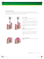
1.2.4 Straumann® Bone Level Implant –
Straumann expertise applied at bone level
Straumann® Bone Level implants are suitable for bone
level treatments in combination with trans- or subgingival
healing. The implant’s rough surface extends to the top
of the implant and the connection is shifted inwards. The
Bone Level Implant uses a conical-cylindrical connection,
the CrossFit™ Connection, together with its corresponding prosthetic CrossFit™ components from the Bone Level
product portfolio. A cylindrical outer contour and a thread
pitch of 0,8 mm, that tapers off in the coronal part of the
implant, provide excellent primary stability.
The Straumann® Standard Plus Narrow Neck implants can
be used as an alternative for narrow interdental spaces.
They are very flexible for indications where esthetic
demands are high. This one-piece design implant has
an external connection with a shoulder diameter of
3,5 mm, an endosteal diameter of 3,3 mm, and a smooth
neck section of 1,8 mm. Narrow neck implants use their
proprietary narrow neck (NN) prosthetic components.
The implant has a thread pitch of 1 mm.
6
1. The Straumann ® Dental Implant System
122461_15X.754.indd Abs1:6
1.2 Implant lines
17.9.2007 9:47:15 Uhr
1.3 Implant-abutment connections
1.3.1 Straumann® synOcta Morse taper connection
The Straumann® synOcta Morse taper connection was
introduced as a design principle for the Straumann® Dental
Implant System in 1986. The mechanically locking friction
fit of the Straumann® synOcta internal connection, with
an 8° cone and an octagon for the repositioning of prosthetic parts, shows improved performance over traditional
external connections. Abutment loosening, even in screwretained situations, has virtually been eliminated.
The Straumann® synOcta connection is available for all
Straumann® Standard, Standard Plus, and Tapered Effect
implants with the Regular Neck (RN) and Wide Neck
(WN) platform.
1.3.2 Straumann® Narrow Neck connection
Straumann® Standard Plus Narrow Neck implants have
an external connection based on an octagon. Its design
is specifically optimized for strength and makes the
Straumann® Narrow Neck Implant one of the most stable
small diameter implants on the market. The Narrow Neck
connection can be used only with proprietary narrow
neck (NN) prosthetic components.
The Narrow Neck connection is available for Straumann®
Standard Plus Narrow Neck implants only.
1. The Straumann ® Dental Implant System
122461_15X.754.indd Abs1:7
1.3 Implant-abutment connections
7
17.9.2007 9:47:16 Uhr
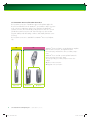
1.3.3 Straumann® Bone Level CrossFit™ Connection
The CrossFit™ Connection of Straumann® Bone Level implants applies the
know-how and benefits from the Straumann® synOcta Morse taper connection
to the connection requirements at bone level. Similar to the Straumann®
synOcta connection, the mechanically locking friction fit of the 15° conicalcylindrical CrossFit™ Connection with four internal grooves has excellent
long-term stability under all loading conditions and virtually eliminates screw
loosening.
The CrossFit™ Connection is available for Straumann® Bone Level implants
only.
NC
Ø 3,3 mm
8
RC
Ø 4,1 mm
1. The Straumann ® Dental Implant System
122461_15X.754.indd Abs1:8
Straumann® Bone Level Ø 4,1 mm and Ø 4,8 mm implants
have the same connection, the regular CrossFit™
Connection (RC), and share the same secondary components.
Straumann® Bone Level Ø 3,3 mm implants feature the
narrow CrossFit™ Connection (NC).
The corresponding secondary components are colorcoded:
p yellow = NC connection
p magenta = RC connection
Ø 4,8 mm
1.3 Implant-abutment connections
17.9.2007 9:47:16 Uhr
1.4 Surfaces
Straumann® implants are manufactured from biocompatible pure Grade 4 titanium. All dental implants are provided
with the SLActive or the SLA® surfaces.
1.4.1 Straumann® SLActive
The SLActive surface features the scientifically proven SLA®
surface topography. Additionally, it exhibits fundamentally
improved surface properties such as hydrophilicity and
chemical activity which significantly accelerate the entire
osseointegration process.
Hydrophilicity
The hydrophilic properties of SLActive enable a larger
accessible surface area for increased blood contact and
bone cell attachment.
Straumann®
SLActive – surface
innovation
p Proven SLA® surface topography
p Hydrophilicity for
a larger accessible surface area
p Chemical activity
promoting faster
osseointegration
Chemical activity
The chemical activity of SLActive provides ideal conditions for direct protein adsorption, stimulating immediate
new bone formation.
1.4.2 Straumann® SLA
The SLA® surface is produced using a large-grit sandblasting technique that
generates a macro-roughness on the titanium surface. This is followed by
acid-etching that superposes a micro-roughness. The resulting topography
offers the ideal structure for cell attachment and is also the basis for the further
developed SLActive surface.
1. The Straumann ® Dental Implant System
122461_15X.754.indd Abs1:9
1.4 Surfaces
9
17.9.2007 9:47:19 Uhr
2. INDICATIONS AND CONTRAINDICATIONS
2.1 Indications
2.2 Contraindications
Straumann® dental implants are suitable for the treatment
of oral endosteal implantation in the upper and lower jaw
and for the functional and esthetic oral rehabilitation of
edentulous and partially dentate patients (unless specific
indications and limitations are present, as stated below).
Straumann® dental implants can also be used for immediate or early implantation following extraction or loss of
natural teeth. Straumann® implants are approved, within
the scope of indications, for immediate restoration in
single tooth gaps and in an edentulous or partially dentate
jaw. Good primary stability and an appropriate occlusal
load are essential. Two or more adjacent implants should
be prosthetically connected together if restored immediately. In the case of immediately restored edentulous
indications, at least 4 implants must be connected together.
Healing phase duration for delayed restorations is given
on page 57. The prosthetic restorations used are single
crowns, bridges and partial or full dentures, which are
connected to the implants by the corresponding elements
(abutments). On page 11, ff. you find implant specific
details about indications, the necessary bone volume and
the spacing between implants and the distance from adjacent teeth.
Serious internal medical problems, bone metabolism disturbances, uncontrolled bleeding disorders, inadequate
wound healing capacity, poor oral hygiene, maxillary
and mandibular growth not completed, poor general
state of health, uncooperative, unmotivated patient, drug
or alcohol abuse, psychoses, prolonged therapy-resistant
functional disorders, xerostomia, weakened immune system, illnesses requiring periodic use of steroids, titanium
allergy, uncontrollable endocrine disorders.
2.1.1 Specific indications for small diameter
(Ø 3,3 mm) implants
As a general rule, always use the largest possible implant
diameter. Because of their reduced mechanical stability,
small diameter implants are used only in cases with
a low mechanical load. Placement in the molar region is
not recommendable. For further restrictions see page 11, ff.
2.2.1 Relative contraindications
Previously irradiated bone, diabetes mellitus, anticoagulation drugs/hemorrhagic diatheses, bruxism, parafunctional
habits, unfavorable anatomic bone conditions, tobacco
abuse, uncontrolled periodontitis, temporomandibular joint
disorders, treatable pathologic diseases of the jaw and
changes in the oral mucosa, pregnancy, inadequate oral
hygiene.
2.2.2 Local contraindications
Inadequate bone volume and/or quality, local root remnants. Attention should be paid to the specific indications
of the small diameter implants and the implants with a
length of 6 mm as specified above.
2.1.2 Specific indications for Straumann® implants with
a length of 6 mm
Because of the reduced surface area for anchorage in the
bone, these implants are to be used solely for the following indications:
p As an additional implant together with longer implants
to support implant-borne reconstructions.
p As an auxiliary implant for implant-borne bar constructions
supporting full dentures in a seriously atrophied mandible.
10
2. Indications and Contraindications
122461_15X.754.indd Abs1:10
2.1 Indications | 2.2 Contraindications
17.9.2007 9:47:25 Uhr
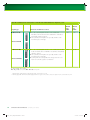
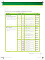
2.3 Implant specific indications
Specific indications for Straumann ® Standard and Standard Plus implants
Implant type
Indications and distinctive features
Minimal
ridge
width*
Minimal
gap
width**
SP Ø 3.3 mm NN
p Small diameter implant for narrow interdental spaces and ridges
5,5 mm
5,5 mm
5,5 mm
7 mm
6 mm
7 mm
Caution
Placement in the molar region is not recommended
S Ø 3.3 mm RN
SP Ø 3.3 mm RN
S Ø 4.1 mm RN
p An alternative in the case of a restricted ridge width
p In view of their lower mechanical strength compared to the
Ø 4,1 mm implants, these implants should be used exclusively
for the following indications:
p Edentulous jaw:
4 implants S/SP Ø 3,3 RN in conjunction with a bar
construction
p Partially edentulous jaw:
In the case of fixed reconstruction, combined with Ø 4,1 mm
implants and splinted with a superstructure
p For oral endosteal implant indications in the maxilla and
mandible, for functional and esthetic rehabilitation of edentulous
and partially edentulous patients
SP Ø 4.1 mm RN
cont.
S = Standard SP = Standard Plus
NN = Narrow Neck Ø 3,5 mm RN = Regular Neck Ø 4,8 mm
* Minimal ridge width: Minimal orofacial ridge width, rounded off to 0,5 mm
** Minimal gap width: Minimal mesial-distal gap width for a single tooth restoration, between adjacent teeth, rounded off to 0,5 mm
2. Indications and Contraindications
122461_15X.754_AlleSprachen.inddAbs1:11 Abs1:11
2.3 Implant specific indications
11
24.9.2007 8:19:41 Uhr
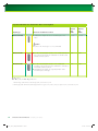
Specific indications for Straumann ® Standard and Standard Plus implants, cont.
Implant type
Indications and distinctive features
Minimal
ridge
width*
Minimal
gap
width**
S Ø 4.8 mm RN
p For oral endosteal implant indications in the maxilla and
7 mm
7 mm
7 mm
8,5 mm
mandible, for functional and esthetic rehabilitation of edentulous
and partially edentulous patients
p The S/SP Ø 4,8 mm implants are especially suited for wider
interdental spaces and ridges
SP Ø 4.8 mm RN
S Ø 4.8 mm WN
SP Ø 4.8 mm WN
p For oral endosteal implant indications in the maxilla and mandible,
for functional and esthetic rehabilitation of edentulous and partially
edentulous patients
p The S/SP Ø 4,8 mm implants are especially suited for wider
interdental spaces and ridges
p S/SP implants with a WN platform are designed for the reconstruction of teeth with a greater neck diameter
S = Standard SP = Standard Plus
RN = Regular Neck Ø 4,8 mm WN = Wide Neck Ø 6,5 mm
* Minimal ridge width: Minimal orofacial ridge width, rounded off to 0,5 mm
** Minimal gap width: Minimal mesial-distal gap width for a single tooth restoration, between adjacent teeth, rounded off to 0,5 mm
12
2. Indications and Contraindications
122461_15X.754_AlleSprachen.inddAbs1:12 Abs1:12
2.3 Implant specific indications
24.9.2007 15:19:14 Uhr
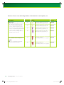
Specific indications for Straumann ® Tapered Effect implants
Implant type
Indications and distinctive features
Minimal
ridge
width*
Minimal
gap
width**
TE Ø 3.3 mm RN
p For oral endosteal implant indications in the maxilla and mandible,
7 mm
7 mm
TE Ø 4.1 mm RN
p For oral endosteal implant indications in the maxilla and mandible,
7 mm
7 mm
TE Ø 4.8 mm WN
p For oral endosteal implant indications in the maxilla and mandible,
8,5 mm
8,5 mm
for functional and esthetic rehabilitation of edentulous and partially
edentulous patients
p Alternative in dental gaps where the roots of adjacent teeth are
close together, where implants with a greater endosteal diameter
are contraindicated
for functional and esthetic rehabilitation of edentulous and partially
edentulous patients
for functional and esthetic rehabilitation of edentulous and partially
edentulous patients
p The TE Ø 4,8 mm implants are especially suited for wider interdental
spaces and ridges
TE = Tapered Effect
RN = Regular Neck Ø 4,8 mm WN = Wide Neck Ø 6,5 mm
* Minimal ridge width: Minimal orofacial ridge width between adjacent teeth, rounded off to 0,5 mm
** Minimal gap width: Minimal mesial-distal gap width for a single tooth restoration, between adjacent teeth, rounded off to 0,5 mm
2. Indications and Contraindications
122461_15X.754_AlleSprachen.inddAbs1:13 Abs1:13
2.3 Implant specific indications
13
24.9.2007 8:19:44 Uhr
Specific indications for Straumann ® Bone Level implants
Implant type
Indications and distinctive features
Minimal
ridge
width*
Minimal
gap
width**
BL Ø 3.3 mm NC
p Small diameter implant for narrow interdental spaces and
5,5 mm
5,5 mm
6 mm
6 mm
7 mm
7 mm
ridges
Caution
Placement in the molar region is not recommended
BL Ø 4.1 mm RC
p For oral endosteal implant indications in the maxilla and mandi-
BL Ø 4.8 mm RC
p For oral endosteal implant indications in the maxilla and
ble, for functional and esthetic rehabilitation of edentulous and
partially edentulous patients
mandible, for functional and esthetic rehabilitation of edentulous
and partially edentulous patients
p The BL Ø 4,8 mm implants are especially suited for wider
interdental spaces and ridges
BL = Bone Level
NC = Narrow CrossFit™ RC = Regular CrossFit™
* Minimal ridge width: Minimal orofacial ridge width, rounded off to 0,5 mm
** Minimal gap width: Minimal mesial-distal gap width for a single tooth restoration, between adjacent teeth, rounded off to 0,5 mm
14
2. Indications and Contraindications
122461_15X.754_AlleSprachen.inddAbs1:14 Abs1:14
2.3 Implant specific indications
24.9.2007 8:19:45 Uhr
3. PREOPERATIVE PLANNING
3.1 Implant position
The implant is the focal point of the restoration. It provides
the basis for planning the surgical procedure. Close communication between the patient, dentist, surgeon and dental
technician is imperative for achieving the desired prosthetic
result.
To establish the topographical situation, the axial orientation
and the choice of implants, we recommend the following:
p Make a wax-up/set-up on the previously prepared
study cast.
p Define the type of superstructure.
The wax-up/set-up can later be used as the basis for a
custom-made X-ray or drill template and for a temporary
restoration.
The implant diameter, implant type, position and number of
implants should be selected individually, taking the anatomy
and spatial circumstances (e.g. malpositioned or inclined
teeth) into account. The measurements given here should be
regarded as minimum guidelines. Only when the minimum
distances are observed is it possible to design the restoration
so that the necessary oral hygiene measures can be carried
out.
The final hard and soft tissue response is influenced by the
position between the implant and the proposed restoration.
Therefore, it should be based on the position of the implantabutment connection. The implant position can be viewed
in three dimensions:
p Mesiodistal
p Orofacial
p Coronoapical
Note
The implant abutments should always be loaded axially.
Ideally, the long axis of the implant is aligned with the
cusps of the opposing tooth. Extreme cusp formation should
be avoided. It can lead to unphysiological loading.
3. Preoperative Planning
122461_15X.754.indd Abs1:15
3.1 Implant position
15
17.9.2007 9:47:31 Uhr
3.1.1 Mesiodistal implant position
The mesiodistal bone availability is an important factor for choosing the implant type and diameter as well as the
interimplant distances in the case of multiple implants. The point of reference on the implant for measuring mesiodistal
distances is always the shoulder, being the most voluminous part of the implant. Note that all distances given in this
chapter are rounded off to 0,5 mm. The following basic rules must be applied:
Rule 1
Distance to adjacent tooth at bone level:
A minimal distance of 1,5 mm from the implant shoulder to the adjacent tooth at bone level (mesial and distal)
is required.
S/SP implants
TE implants
≥1,5 mm
BL implants
≥1,5 mm
≥1,5 mm
Rule 2
Distance to adjacent implants at bone level:
A minimal distance of 3 mm between two adjacent implant shoulders (mesiodistal) is required.
S/SP implants
TE implants
≥3 mm
16
3. Preoperative Planning
122461_15X.754.indd Abs1:16
BL implants
≥3 mm
≥3 mm
3.1 Implant position
17.9.2007 9:47:32 Uhr
3.1.1.1 Examples for single tooth gaps
For single tooth restoration, the implant is placed centered within the single
tooth gap. The following examples show how rule 1 is implemented.
Straumann® Standard, Standard Plus, and Tapered Effect implants
For Straumann® soft tissue level implants, the gap size has to be considered
for the selection of the shoulder diameter (NN, RN, WN). In order to make
use of the gap width in conjunction with rule 1, the following approximation
can be used.
Distance between adjacent
teeth at bone level
0,5 mm
Gap width
0,5 mm
The distance between adjacent teeth at bone level is approximately 1 mm
(2 x 0,5 mm) more than the gap width. Hence, applying rule 1, the gap width
must be 2 mm wider than the implant shoulder.
3. Preoperative Planning
122461_15X.754.indd Abs1:17
3.1 Implant position
17
17.9.2007 9:47:42 Uhr
Shoulder diameter
Gap width
D (mm)
amin (mm)
Distance between adjacent teeth at bone level
b min (mm)
Ø 3,5 (NN)
5,5
6,5
Ø 4,8 (RN)
7
8
Ø 6,5 (WN)
8,5
9,5
Rule
D + 2 mm
D + 3 mm*
S/SP/TE implants
b
a
D
≥1,5 mm ≥1,5 mm
*Rule 1 applied on both implant sides
The Diagnostic T (see page 23), applied in the patient’s mouth or on the cast, can be used to obtain an initial measurement of the gap width for the
choice of the implant shoulder diameter and prosthetic reconstruction.
Straumann® Bone Level implants
For Straumann® Bone Level implants, the distance between adjacent teeth at bone level determines the implant
diameter.
Implant diameter
Gap width
D (mm)
amin (mm)
Distance between adjacent teeth at bone level
b min (mm)
BL Ø 3,3
5,5
6,5
BL Ø 4,1
6
7
BL Ø 4,8
7
8
Rule
D + 2 mm
D + 3 mm*
BL implants
b
a
D
≥1,5 mm ≥1,5 mm
*Rule 1 applied on both implant sides
18
3. Preoperative Planning
122461_15X.754.indd Abs1:18
3.1 Implant position
17.9.2007 9:47:44 Uhr
3.1.1.2 Examples of multiple tooth gaps
The following examples show how rules 1 and 2 are implemented in multiple tooth gaps. The measurement is made
at bone level from the adjacent tooth to the center of the implant and between implant centers. The minimal distance
of 3 mm between two adjacent implant shoulders (rule 2) is important to facilitate flap adaptation, avoid proximity of
secondary components and provide adequate space for maintenance and home-care.
Straumann® Standard, Standard Plus, and Tapered Effect implants
S/SP/TE implants
L
a
b
D1
≥3 mm
≥1,5 mm
c
Shoulder
diameter D1 (mm)
Shoulder
diameter D2 (mm)
Ø 3,5 (NN)
Ø 3,5 (NN)
3
Ø 3,5 (NN)
Ø 4,8 (RN)
Ø 3,5 (NN)
amin (mm)
b min (mm)
c min (mm)
L min (mm)
6,5
3
12,5
3
7
4
14
Ø 6,5 (WN)
3
8
5
16
Ø 4,8 (RN)
Ø 4,8 (RN)
4
8
4
16
Ø 4,8 (RN)
Ø 6,5 (WN)
4
8,5
5
17,5
Ø 6,5 (WN)
Ø 6,5 (WN)
5
9,5
5
19,5
c min (mm)
L min (mm)
D2
≥1,5 mm
Straumann® Bone Level implants
Implant diameter Implant diameter
amin (mm)
D1 (mm)
D2 (mm)
BL implants
L
a
b
D1
c
D2
≥1,5 mm ≥3 mm ≥1,5 mm
b min (mm)
BL Ø 3,3
BL Ø 3,3
3
6,5
3
12,5
BL Ø 3,3
BL Ø 4,1
3
7
3,5
13,5
BL Ø 3,3
BL Ø 4,8
3
7
4
14
BL Ø 4,1
BL Ø 4,1
3,5
7
3,5
14
BL Ø 4,1
BL Ø 4,8
3,5
7,5
4
15
BL Ø 4,8
BL Ø 4,8
4
7,5
4
15,5
3. Preoperative Planning
122461_15X.754.indd Abs1:19
3.1 Implant position
19
17.9.2007 9:47:47 Uhr
3.1.2 Orofacial implant position
The facial and palatal bone layer must be at least 1 mm
thick in order to ensure stable hard and soft tissue conditions. The minimal orofacial ridge widths for individual
implant types are given in the indication tables on page
11, ff. Within this limitation, a restoration-driven orofacial
implant position and axis should be chosen such that
screw retained restorations are possible.
≥1 mm
Bone layer at least
1 mm in thickness
Caution
An augmentation procedure is indicated, where the orofacial bone wall is less than 1 mm or a layer of bone is
missing on one or more sides. This technique should be
employed only by dentists who have adequate experience in the use of augmentation procedures.
≥1 mm
Choose the orofacial
implant position and
axis so that the screw
channel of the screwretained restoration is
located behind the
incisial edge.
20
3. Preoperative Planning
122461_15X.754.indd Abs1:20
3.1 Implant position
17.9.2007 9:47:48 Uhr
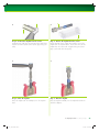
3.1.3 Coronoapical implant position
Straumann® dental implants allow for flexible coronoapical implant positioning, depending on individual anatomy, implant site, the type of restoration
planned and preference. In the anterior area, a deeper coronoapical implant
position is better for esthetic reasons. In this situation, the use of Straumann®
Standard Plus, Tapered Effect or Bone Level implants is recommended. The
following illustration shows the coronoapical implant position for these implants.
2,8 mm
1,8 mm
Standard
Standard Plus
Tapered Effect
Bone Level
Straumann® Standard implants
Straumann® Standard implants with a smooth neck section of 2,8 mm are
submerged in the bone as far as the margin of the SLA®/SLActive surface.
Straumann® Standard Plus and Tapered Effect implants
Straumann® Standard Plus and Tapered Effect implants with a smooth neck
section of 1,8 mm are submerged in the bone as far as the margin of the
Straumann® SLA/SLActive surface. Optionally they can be placed slightly
deeper if necessary.
Ideally, in the esthetic region, the implant shoulder should be positioned about
1 mm apical to the cemento-enamel junction (CEJ) of the contralateral tooth or
2 mm subgingival of the prospective gingival margin (see also references on
page 22).
Caution
If a Straumann® Standard Plus or a Tapered Effect implant is inserted deeper
as the margin of the Straumann® SLA/SLActive surface, the preparation depth
must be increased accordingly (see also page 58).
3. Preoperative Planning
122461_15X.754_AlleSprachen.inddAbs1:21 Abs1:21
3.1 Implant position
21
24.9.2007 8:19:46 Uhr
Straumann® Bone Level implants
Straumann® Bone Level implants are best set with the outer rim of the small 45° sloping edge (chamfer) at bone level.
Ideally, in the esthetic region, the implant shoulder should be positioned about 3 – 4 mm subgingival of the prospective
gingival margin (see also use of Bone Level transfer part on page 46).
In a scalloped situation, place the mesial/distal point of the outer rim of the
implant to bone level. The lingual/palatinal wall will then extend slightly over
the top line of the implant. The buccal wall is located somewhat below the
implant edge.
For further information regarding surgical procedures in cases pertaining to esthetics, please refer to the following
scientific publications:
22
3. Preoperative Planning
122461_15X.754.indd Abs1:22
ITI Consensus Paper
ITI Treatment Guide
Buser D./ Martin W./
Belser U.:
Optimizing esthetics
for implant restorations in the anterior
maxilla: anatomic
and surgical considerations.
Int J Oral Maxillofac
Implants, 2004; 19
Suppl: 43–61.
Buser D./ Martin W,
Belser U.:
Surgical considerations for single-tooth
replacements in the
esthetic zone:
standard procedure
in sites without bone
deficiencies.
ITI Treatment Guide.
Implant Therapy in the
Esthetic Zone. SingleTooth Replacements.
2007, Vol. 1; 26–37.
Quintessence
Publishing Co. Ltd,
Berlin.
3.1 Implant position
17.9.2007 9:47:56 Uhr
3.2 Planning aids
3.2.1 Mesiodistal and orofacial space requirements
3.2.1.1 Diagnostic T for Straumann® Standard, Standard Plus, and
Tapered Effect implants
By using the Diagnostic T in the patient‘s mouth or on the cast, an initial
impression of the spatial relations for the choice of the implant shoulder
diameter and prosthetic reconstruction can be obtained. The pictograms
on the instruments show which arm is used for which measurement.
The use of additional planning methods, such as the use of a drill template
(see page 28), is recommended.
X = Minimum occlusal space requirement
(for the lowest prosthetic restoration option)
Y = Interproximal distance (gap width)
Z = Implant center to adjacent tooth
(1/2 the gap width)
Note
Currently, a Diagnostic T for
Straumann® Bone Level implants is
not available.
Determining the implant shoulder diameter in a
single tooth gap
Implant shoulders:
NN = Narrow Neck (Ø 3,5 mm)
RN = Regular Neck (Ø 4,8 mm)
WN = Wide Neck (Ø 6,5 mm)
Determining the minimal distance between implant axis and adjacent teeth
Minimum vertical space requirement for access
with surgical instruments
3. Preoperative Planning
122461_15X.754.indd Abs1:23
3.2 Planning aids
23
17.9.2007 9:48:01 Uhr
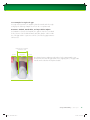
3.2.1.2 Straumann® Implant Distance Indicator
Two types of distance indicators are available:
p For Straumann® Standard, Standard Plus and Tapered Effect implants (Art. No. 046.148)
p For Straumann® Bone Level implants (Art. No. 026.0901)
The four discs of the implant distance indicators display the shoulder diameters of Straumann® implants. The implant
distance indicators can be used to check the available space before the start of treatment or intraoperatively to mark
the desired implant site.
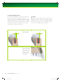
After flap opening and precise positioning of the disc(s)
at the planned implantation site, it is possible to drill
through the perforation in the disc(s) with the round
bur Ø 1,4 mm (Art. No. 044.022) in order to mark
the centre of the implant bed.
Intraoperative use of the distance indicator
before flap opening
Round bur
Ø 1,4 mm
Distance indicator for Straumann ® Standard, Standard Plus, and Tapered Effect implants
Straumann® Implant Distance Indicator for Straumann®
Standard, Standard Plus and Tapered Effect implants
(Art. No. 046.148)
24
Leg label
Disk diameter
Corresponding implants
Leg 1
RN Ø 4,8
Ø 4,8 mm
all Regular Neck (RN) implants
Leg 2
RN Ø 4,8
Ø 4,8 mm
all Regular Neck (RN) implants
Leg 3
NN Ø 3,5
Ø 3,5 mm
all Narrow Neck (NN) implants
Leg 4
WN Ø 6,5
Ø 6,5 mm
all Wide Neck (WN) implants
3. Preoperative Planning
122461_15X.754.indd Abs1:24
3.2 Planning aids
17.9.2007 9:48:08 Uhr
Distance Indicator for Straumann ® Bone Level implants
Straumann® Implant Distance Indicator for Straumann®
Bone Level implants (Art. No. 026.0901)
Leg label
Disk diameter
Corresponding implants
Leg 1
BL Ø 4,1
Ø 4,1 mm
Bone Level implants Ø 4,1 mm
Leg 2
BL Ø 4,1
Ø 4,1 mm
Bone Level implants Ø 4,1 mm
Leg 3
BL Ø 3,3
Ø 3,3 mm
Bone Level implants Ø 3,3 mm
Leg 4
BL Ø 4,8
Ø 4,8 mm
Bone Level implants Ø 4,8 mm
3.2.2 Determining the vertical bone availability
The vertical bone availability determines the maximal allowable length of the implant that can be placed. To make
it easier in determining the vertical bone availability, the use of an X-ray template with X-ray reference spheres is
recommended.
3.2.2.1 X-ray reference sphere
The X-ray reference sphere (Art. No. 049.076V4) has
a diameter of 5 mm. The image of the sphere on the
X-ray provides the reference value for the magnification
scale. To prepare a reference sphere carrying template,
the selected implant positions are marked on the study
cast. The X-ray reference spheres are fixed at the marked
points. The vacuum-formed template is then made with
the spheres. The subsequent X-ray shows the vertical bone
availability and mucosal thickness, from which the corresponding implant length and type can be derived, in
consideration of the enlargement factor.
3. Preoperative Planning
122461_15X.754.indd Abs1:25
3.2 Planning aids
25
17.9.2007 9:48:14 Uhr
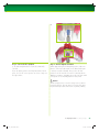
3.2.2.2 X-ray templates
The X-ray templates are used for measurement and comparison. They also assist the user in selecting the suitable
implant type, diameter and length. The following X-ray
templates are available:
(049.076V4) = Ø 5,0 mm
S
Ø 3,3 mm
RN
p For Straumann® Standard and Standard Plus implants
(Art. No. 150.215)
p For Straumann® Tapered Effect implants
(Art. No. 150.230)
p For Straumann® Bone Level implants
(Art No. 150.216)
SP
Ø 3,3 mm
NN
SP
Ø 3,3 mm
RN
S
= Straumann Standard implant
NN = Narrow Neck (Ø 3,5 mm)
SP
= Straumann Standard Plus implant
RN = Regular Neck (Ø 4,8 mm)
SP
Ø 4,1 mm
RN
SP
Ø 4,8 mm
RN
WN = Wide Neck
SP
Ø 4,8 mm
WN
(Ø 6,5 mm)
(049.076V4) = Ø 5,5 mm
S
Ø 3,3 mm
RN
S
Ø 4,1 mm
RN
S
Ø 4,8 mm
RN
S
Ø 4,8 mm
WN
SP
Ø 3,3 mm
RN
SP
Ø 4,1 mm
RN
SP
Ø 4,8 mm
RN
SP
Ø 4,8 mm
WN
max. 0,4 mm
07/07 150.215
E20807
SP
Ø 3,3 mm
NN
X-ray template for Straumann® Standard and Standard Plus implants
(Art. No. 150.215)
Tapered Effect Implant
1.0 : 1
(049.076V4) = Ø 5,0 mm
Ø 3,3 mm
RN
0
2
4
6
Ø 4,1 mm
RN
Ø 4,8 mm
WN
Ø 3,3 mm
RN
Ø 4,1 mm
RN
Ø 4,8 mm
WN
0
2
4
6
8
10
12
14
16
8
10
12
14
16
0
2
4
6
8
10
12
14
16
Tapered Effect Implant
1.1 : 1
(049.076V4) = Ø 5,5 mm
Ø 3,3 mm
RN
0
2
4
6
Ø 4,1 mm
RN
Ø 4,8 mm
WN
Ø 3,3 mm
RN
Ø 4,1 mm
RN
Ø 4,8 mm
WN
0
2
4
6
8
10
12
14
16
8
10
12
14
16
0
2
4
6
8
10
12
14
16
E20807
The first stage consists of comparing the size of the X-ray
reference sphere on the patient’s X-ray with the size of
the reference sphere on the template. By superimposing
the two pictures, the correct scale can be found. Then,
the spatial relations around the implant position are
determined and the implant length and insertion depth
are established.
S
Ø 4,8 mm
WN
07/07 150.230
Determining each magnification factor or scale is facilitated
by showing the X-ray reference sphere on the template
(next to the scale reference).
S
Ø 4,8 mm
RN
0,4 mm
Similar to the distortions that occur in X-rays, the implant
dimensions are shown on the individual templates with the
corresponding distortion factors (1:1 to 1,7:1).
S
Ø 4,1 mm
RN
RN = Regular Neck (Ø 4,8 mm)
WN = Wide Neck
(Ø 6,5 mm)
X-ray template for Straumann® Tapered Effect implants
(Art. No. 150.230)
1.0 : 1
6
Straumann® Bone Level Implant
2
4
Ø 4.1 mm
Ø 3.3 mm
Ø 4.8 mm
Ø 4.1 mm
6
8
10
12
14
16
1.3 : 1
(049.076V4) = Ø 6.5 mm
(049.076V4) = Ø 5.5 mm
Ø 3.3 mm
Straumann® Bone Level Implant
0
4
2
6
4
6
8
10
12
14
16
8
10
12
14
16
-$%)"$('+%. * # &"& ,,
Example:
scale 1,1:1 = reference sphere Ø 5,5 mm
Ø 3.3 mm
8
10
12
14
16
1.1 : 1
2
Ø 4.1 mm
0
4
Straumann® Bone Level Implant Ø 4.8 mm
0
Ø 4.8 mm
0.4 mm
B11106
2
Ø 3.3 mm
11/06 150.216
0
Ø 4.1 mm
1.2 : 1
(049.076V4) = Ø 6.0 mm
(049.076V4) = Ø 5.0 mm
Straumann® Bone Level Implant Ø 4.8 mm
X-ray template for Straumann® Bone Level implants
(Art. No. 150.216)
26
3. Preoperative Planning
122461_15X.754.indd Abs1:26
3.2 Planning aids
17.9.2007 9:48:17 Uhr
To calculate the effective bone availability the following
formula should be used:
X-ray reference sphere 5 mm x
bone availability (X-ray*)
Reference sphere diameter on the X-ray
=
effective
bone
availability
* Taking into consideration all implant-related anatomic structures
(e.g. mandibular canal, sinus maxillaris, etc.)
Example for a measured bone availability and reference
sphere diameter on the X-ray of 13 mm and 6 mm (+ 20 %
distortion), respectively.
5 mm x 13 mm
6 mm
=
10,8 mm
max. 0.4 mm
Additional length of the drill tip:
Note
Due to the construction and function of the drills, the drill
tip is a maximum of 0,4 mm longer than the implant insertion
depth. This additional length must be taken into consideration during the planning phase.
Additional length of the drill tip
See also the section “Measurement and analysis procedure for operation planning“ in the DVD
“Straumann® Dental Implant System–Surgical“ (Art. No. 150.541)
3. Preoperative Planning
122461_15X.754.indd Abs1:27
3.2 Planning aids
27
17.9.2007 9:48:19 Uhr
3.2.3 Surgical drill template
A custom-made drill template facilitates planning and preparation of the implant bed and enables precise use of the cutting instruments. The planning
basis for fabricating this template should be the desired prosthetic result.
3.2.3.1 Vacuum-formed drill template
A conventional surgical drill template can be produced with the vacuumformed
template components.
The 10 mm long metal pin functions as the
X-ray reference pin.
After the pin is integrated into the template,
the planned implant axis and position become
visible on the X-ray.
The drill sleeve is then secured in a drill
template.
Note
For verification, an X-ray with the drill template may also be taken.
A Ø 2,2 mm pilot drill is then used for the subsequent drilling.
For further information see “Fabrication and use of an individual drill template“
(Art. No. 152.290), where two fabrication methods are shown gradually in a
step-by-step.
28
3. Preoperative Planning
122461_15X.754.indd Abs1:28
3.2 Planning aids
17.9.2007 9:48:19 Uhr
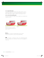
3.2.3.2 Thermoplastic drill template
1. Drill a hole into the previously determined implant position and in the
plaster anatomic cast on its axis.
2. Check the implant position by inserting the pin into the drilled hole.
3. Heat the template in water until it is soft and transparent.
4. Place the template on the guide pin and press onto the plaster teeth.
After it has cooled off and has been disinfected, the thermoplastic drill template determines exactly how the Ø 2,2 mm pilot drill is to be guided.
Drill hole template for single tooth gap
Drill hole template for free end saddle
Note
For more detailed information please refer to the brochure
“The efficient aid for case planning and implant bed preparation:
Thermoplastic drill template“ (Art. No. 152.356).
3. Preoperative Planning
122461_15X.754.indd Abs1:29
3.2 Planning aids
29
17.9.2007 9:48:20 Uhr
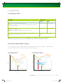
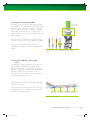
4. SURGICAL PROCEDURES
4.1 Implant bed preparation
Preparing the implant bed is done using one surgical kit for all Straumann®
dental implants and covers two main steps:
Steps
Influencing factors
1. Basic implant bed preparation
Ridge preparation
Endosteal implant diameter
Basic implant bed preparation
involves ridge preparation and
twist drilling. For twist drilling, the
endosteal diameter of the implant
(3,3/4,1/4,8 mm), not the implant
type or the bone class, determines
the instrumentation used.
Twist drilling
2. Fine implant bed preparation
Profile drilling
Implant type and bone class
Fine implant bed preparation
involves profile drilling and tapping.
For tapping, the implant type (S/SP/
TE/BL) and bone class determine the
instrumentation used.
Tapping
Before starting and during the surgical procedure, the following points must be
considered:
p Check all instruments for completeness and function. An adequate stock of
implants and sterile spare instruments should always be available.
p Do not use cutting instruments more than 10 times. The table “Surgery
Tracking Sheet for Straumann Cutting Instruments” (Art. No. 152.755)
facilitates tracking.
p Ensure ample cooling of drills with pre-cooled (5 °C, 41 °F) physiological
sterile saline solution (NaCl) or Ringer’s solution.
p Do not exceed the indicated speed for drills (see graphics and tables on
page 31, ff.).
p Use drills in ascending order of their diameter.
p Use only light pressure and an intermittent drilling technique.
30
4. Surgical procedures
122461_15X.754.indd Abs1:30
4.1 Implant bed preparation
17.9.2007 9:48:26 Uhr
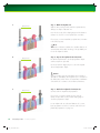
4.1.1. Basic implant bed preparation
After opening the gingiva, the basic implant bed preparation begins with preparing the alveolar ridge (Step 1) and
marking the implantation site with a round bur (Step 2). After that, the implant bed preparation with pilot and
twist drills follows (Step 3–7), according to the endosteal implant diameter chosen in the preoperative planning (see
Chapter 3, page 15, ff.).
1
800 rpm max.
Step 1 – Prepare the alveolar ridge
Carefully reduce and smooth a narrow tapering ridge with a large round bur.
This will provide a flat bone surface and a sufficiently wide area of bone.
Note
When choosing the implant length (SLActive/SLA® surface), the vertical
reduction of the bone has to be considered.
2
800 rpm max.
Step 2 – Mark the implantation site
Mark the implantation site determined during the implant position planning
with the Ø 1,4 mm round bur. The implant distance indicator can be used for
that purpose (see pages 24 and 25).
Widen and correct the position of the mark with the Ø 2,3 mm or the
Ø 3,1 mm round bur, if necessary.
4. Surgical procedures
122461_15X.754.indd Abs1:31
4.1 Implant bed preparation
31
17.9.2007 9:48:26 Uhr
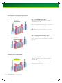
3
800 rpm max.
Step 3 – Mark the implant axis
With the Ø 2,2 mm pilot drill, mark the implant axis by
drilling to a depth of about 6 mm.
Insert the short side of the depth gauge with the distance
indicator to check for correct implant axis orientation.
If necessary, correct unsatisfactory implant axis orientation
in the following step.
Note
The distance indicator visualizes the shoulder diameter of
4,8 mm (RN) and enables checking of the probable position of the implant shoulder.
4
800 rpm max.
Step 4 – Prepare the implant bed to Ø 2,2 mm
Pre-drill the implant bed to the final preparation depth
with the Ø 2,2 mm pilot drill.
Use the Ø 2,2 mm alignment pin to check the implant
axis and preparation depth.
Caution
At this point take an X-ray, particularly with vertically reduced bone availability. The alignment pin is inserted into
the drilled area, which allows a comparative visualization
of the drill hole in relation to the anatomical structures.
5
600 rpm max.
Step 5 – Widen the implant bed to Ø 2,8 mm
Continue with the implant bed preparation.
If necessary, correct the implant position with the
Ø 2,8 mm pilot drill. Use the Ø 2,8 depth gauge to
check the preparation depth.
For an implant with an endosteal diameter of 3,3 mm,
basic preparation ends here. Continue with the fine implant bed preparation on page 35.
32
4. Surgical procedures
122461_15X.754.indd Abs1:32
4.1 Implant bed preparation
17.9.2007 9:48:28 Uhr
6
500 rpm max.
For Ø 4,1 mm and Ø 4,8 mm implants
Step 6 – Widen the implant bed to Ø 3,5 mm
Continue with the Ø 3,5 mm twist drill and check the final
preparation depth with the Ø 3,5 mm depth gauge.
For an implant with an endosteal diameter of 4,1 mm,
basic preparation ends here. Continue with the fine implant bed preparation on page 35.
7
400 rpm max.
For Ø 4,8 mm implants
Step 7 – Widen the implant bed to Ø 4,2 mm
Continue with the Ø 4,2 mm Straumann® Twist Drill PRO
and check the final preparation depth with the Ø 4,2 mm
depth gauge.
Continue with the fine implant bed preparation on
page 35.
Note
To facilitate introducing the instruments into the bone cavity, the bony margin of the drill hole can be beveled slightly
using a large round bur or with an SP profile drill corresponding to the diameter of the last twist/spiral drill employed.
The profile drills are inserted only a fraction into the drill hole.
4. Surgical procedures
122461_15X.754.indd Abs1:33
4.1 Implant bed preparation
33
17.9.2007 9:48:32 Uhr
The following table summarizes the use of instruments for the basic implant bed preparation according to the endosteal
implant diameter. All drills are available in a short and a long version and as multi-use as well as single-patient drills
(see also Surgical Instruments on page 58). The table lists the short multi-use drills only.
Instrumentation for basic implant bed preparation
Step
Art. No.
1
Prepare ridge
044.004
Round bur, Ø 3,1 mm
2
Mark
implant
position
044.022
Round bur, Ø 1,4 mm
044.003
Round bur, Ø 2,3 mm
044.004
Round bur, Ø 3,1 mm
044.210
Pilot drill 1, short, Ø 2,2 mm
046.455
Depth gauge, with distance
indicator, Ø 2,2/2,8 mm
044.210
Pilot drill 1,
short,
Ø 2,2 mm
046.458
Alignment pin,
Ø 2,2 mm,
straight
044.214
Pilot drill 2,
short,
Ø 2,8 mm
046.455
Depth gauge,
with distance indicator,
Ø 2,2/2,8 mm
044.218
Twist drill,
short,
Ø 3,5 mm
046.450
Depth gauge Ø 3,5 mm
044.254
Twist drill PRO,
short,
Ø 4,2 mm
046.451
Depth gauge Ø 4,8 mm
3
4
5
6
7
34
Mark
implant axis
Prepare
implant bed
to Ø 2,2 mm
Prepare
implant bed
to Ø 2,8 mm
Prepare
implant bed
to Ø 3,5 mm
Prepare
implant bed
to Ø 4,2 mm
4. Surgical procedures
122461_15X.754.indd Abs1:34
Product
max.
rpm
Endosteal Ø (mm)
Ø 3.3
Ø 4.1
Ø 4.8
800
800
800
800
600
500
400
4.1 Implant bed preparation
17.9.2007 9:48:34 Uhr
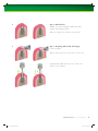
4.1.2. Fine implant bed preparation
The fine implant bed preparation encompasses profile drilling and subsequent tapping. Instrumentation depends on the
implant type, the endosteal implant diameter, and the bone class.
Profile drilling
The profile drill prepares the implant bed for a specific Straumann® implant.
p Straumann® Standard Plus, Tapered Effect, and Bone Level implants require profile drilling with specific instruments.
This is independent of the bone class.
p Straumann® Standard implants are inserted without profile drilling.
The profile drills are clearly marked SP, TE, or BL. The (first) diameter indicated on the label corresponds to the diameter of the guide cylinder and, accordingly, to the diameter of the implant bed before profile drilling. All Straumann®
profile drills are available in a short and a long version.
Straumann® Standard Plus
Profile Drill
Insertion depth on
SLActive/SLA ®surface
margin level
Insertion depth on
implant shoulder
Straumann® Tapered Effect
Profile Drill
Insertion depth on
SLActive/SLA ®surface
margin level
Straumann ® Bone Level
Profile Drill
Insertion depth on
implant shoulder
Insert the Straumann® Standard Plus
Profile Drill according to the planned
insertion depth of the implant.
Insert the Straumann® Tapered Effect
Profile Drill according to the planned
insertion depth of the implant.
Insert the Straumann®
Bone Level Profile
Drill up to the
planned implant
shoulder level.
400 rpm max.
300 rpm max.
300 rpm max.
Note
Due to the unflared neck portion, the Straumann®
Standard Plus Ø 3,3 mm NN and Standard Plus
Ø 4,8 mm RN implants are inserted without profile
drilling.
Caution
The profile drills are suitable only for the corresponding
implant type!
4. Surgical procedures
122461_15X.754.indd Abs1:35
A dent on the
front of the guide
cylinder makes
the drills better
distinguishable
from Tapered
Effect profile drills.
4.1 Implant bed preparation
35
17.9.2007 9:48:38 Uhr
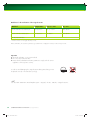
Tapping
Tapping prepares the implant bed for a specific thread type. It is an optional step that gives the surgeon the flexibility
to adjust the surgical protocol to the bone class to help achieve optimal primary stability. It is recommended in dense bone
and with large diameter implants in order to keep the insertion torque in a desirable range. The table below summarizes
suggested tap usage.
Tapping according to bone class
Bone
Classes*
S, SP implants
BL, TE implants
Endosteal diameter
Endosteal diameter
Ø 3.3 mm
Ø 4.1 mm
Ø 4.8 mm
Ø 3.3 mm
Ø 4.1 mm
Ø 4.8 mm
Class 1
full
full
full
full
full
full
Class 2
coronal
coronal
full
full
full
full
Class 3
full
full
Class 4
full
full
* Class 1: hardest bone/Class 4: soft bone
coronal = thread tapping in the coronal area of the implant bed
full = thread tapping over full depth of the implant bed
Straumann® Standard and Standard Plus taps
Tap for ratchet
Tap for adapter
Straumann® Bone Level and
Tapered Effect taps
Tap for adapter
Coupling for ratchet
Coupling for
adapter
Coupling for adapter
Label for implant type
Depth mark
Depth mark
Cutting head
36
Cutting head
S/SP taps are used in the coronal area only or over the full
depth of the implant bed, depending on implant diameter and
bone class (see table above).
If a BL/TE tap is used, it should always
be inserted over the full depth of the implant bed preparation (see table above).
The S/SP taps are available for adapter and for ratchet.
Two lengths are offered for the ratchet version.
BL/TE taps are available for adapter
only.
15 rpm max.
15 rpm max.
4. Surgical procedures
122461_15X.754.indd Abs1:36
Caution
Straumann® taps
are to be used
only for the corresponding implant
type!
4.1 Implant bed preparation
17.9.2007 9:48:44 Uhr
Two types of Straumann® taps are available: taps for ratchet and taps for adapter. The taps for ratchet are directly coupled
to the ratchet, and are for tapping with ratchet only. The taps for adapter can be coupled either to a handpiece or a ratchet
adapter and allow both, tapping with the handpiece or with the ratchet.
Tapping with handpiece
Tapping with ratchet
Connect the tap for adapter to the handpiece via the handpiece adapter. Do not exceed 15 rpm.
For tapping with the ratchet use the tap for ratchet or connect a
ratchet adapter to the tap for adapter. After inserting the tap into
the cavity, the ratchet is placed on its coupling and the thread
is tapped with a slow rotating movement. The holding key is
used as a stabilizer to maintain the direction of tapping during
the procedure.
Holding key
Handpiece
Ratchet
Handpiece adapter
Ratchet adapter
Tap for adapter
Tap for ratchet
Tap for adapter
4. Surgical procedures
122461_15X.754.indd Abs1:37
4.1 Implant bed preparation
37
17.9.2007 9:48:45 Uhr
4.1.3 Examples for fine implant bed preparation
Straumann® Standard and Standard Plus implants
1
400 rpm max.
Step 1 – Standard Plus profile drill
Shape the coronal part of the implant bed with the
Standard Plus profile drill.
Insert the Standard Plus profile drill up to the planned
implant shoulder level (see page 35).
Note
For Standard implants, profile drilling is not required.
2
15 rpm max.
Step 2 – Tapping the thread in dense bone
Pre-tap the implant bed with the S/SP tap according to
the bone class and the endosteal diameter (see table on
page 36).
Straumann® Tapered Effect implants
1
300 rpm max.
Step 1 – TE profile drill
Shape the coronal part of the implant bed with the
TE profile drill.
Insert the TE profile drill up to the planned implant
shoulder level (see page 35).
38
4. Surgical procedures
122461_15X.754.indd Abs1:38
4.1 Implant bed preparation
17.9.2007 9:48:48 Uhr
2
15 rpm max.
Step 2 – Tapping the thread in dense bone
Pre-tap the entire length of the implant bed according to
the bone class and the endosteal diameter (see table on
page 36) with the BL/TE tap.
Straumann® Bone Level implants
The following example shows fine implant bed preparation for a Ø 4,1 mm Bone Level Implant of 12 mm of length
placed in bone class 1 or 2, making pre-tapping necessary (see table on page 36). These steps follow the basic
implant bed preparation (see pages 32 and 33).
1
300 rpm max.
2
15 rpm max.
Step 1 – Bone Level profile drill
Prepare the implant bed with the Straumann® Bone Level
profile drill. Insert the profile drill up to the planned
implant shoulder level (see page 35).
Step 2 – Tapping the thread in dense bone
Pre-tap the entire length of the implant bed with the
BL/TE tap.
4. Surgical procedures
122461_15X.754.indd Abs1:39
4.1 Implant bed preparation
39
17.9.2007 9:48:52 Uhr
The following table summarizes the use of profile drills and taps for the fine implant bed preparation for all Straumann®
implants. All profile drills are available in a short and a long version. S/SP taps are available for ratchet and for
adapter. The table lists the short profile drills, and the taps for adapter only.
Straumann ®
Standard Implant
Instrumentation for fine implant bed preparation
40
Art. No.
Product
044.086
SP Profile drill, short, Ø 2,8 mm, RN
044.088
SP Profile drill, short, Ø 3,5 mm, RN
044.084
SP Profile drill, short, Ø 4,2 mm, WN
044.575
S/SP Tap, Ø 3,3 mm, for adapter
044.577
S/SP Tap, Ø 4,1 mm, for adapter
044.579
S/SP Tap, Ø 4,8 mm, for adapter
044.701
TE Profile drill, short, Ø 2,8 mm RN
044.705
TE Profile drill, short, Ø 3,5 mm RN
044.703
TE Profile drill, short, Ø 4,2 mm WN
026.2303
BL Profile drill, Ø 3,3 mm, short
026.4303
BL Profile drill, Ø 4,1 mm, short
026.6303
BL Profile drill, Ø 4,8 mm, short
026.2310
BL/TE Tap, Ø 3,3 mm, for adapter
026.4310
BL/TE Tap, Ø 4,1 mm, for adapter
026.6310
BL/TE Tap, Ø 4,8 mm, for adapter
4. Surgical procedures
122461_15X.754.indd Abs1:40
Max.
rpm
Thread
pitch
S Ø 3.3 RN
S Ø 4.1 RN
S Ø 4.8 RN
400
1
15
1,25
1,25
300
300
0,8
15
0,8
0,8
4.1 Implant bed preparation
17.9.2007 9:48:56 Uhr
S Ø 4.
Required step
Required in dense bone only
* Due to the unflared neck portion, the Straumann
®
Standard Plus Ø 3,3 mm NN and
Standard Plus Ø 4,8 mm RN implants are inserted without profile drilling.
Straumann ®
Standard Plus Implant
8 RN
S Ø 4.8 WN
SP Ø 3.3 NN
SP Ø 3.3 RN
SP Ø 4.1 RN
SP Ø 4.8 RN
SP Ø 4.8 WN
Straumann ®
Tapered Effect Implant
Straumann ®
Bone Level Implant
TE Ø 3.3 RN
BL Ø 3.3 NC
TE Ø 4.1 RN
TE Ø 4.8 WN
BL Ø 4.1 RC
BL Ø 4.8 RC
*
*
4. Surgical procedures
122461_15X.754.indd Abs1:41
4.1 Implant bed preparation
41
17.9.2007 9:49:02 Uhr
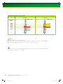
4.2 Opening the implant package
Straumann® SLActive
Step 1 – Open the blister and remove the vial
1
Note
The blister ensures the sterility of the implant. Do not open
the blister until immediately prior to implant placement.
2
Step 2 – Open the vial
Turn the lid in counterclockwise direction. Keep the vial
upright to prevent the liquid from flowing out.
Note
If the implant carrier is not firmly attached to the lid, screw
in the lid once again.
3
Step 3 – Detach the implant carrier
Detach the implant carrier from the lid by pulling it off
manually.
Note
After removing the implant from the solution, the chemical
activity of SLActive is ensured for 15 minutes.
42
4. Surgical procedures
122461_15X.754.indd Abs1:42
4.2 Opening the implant package
17.9.2007 9:49:08 Uhr
Straumann® SLA
1
Step 1 – Open the safety cap
Open the safety cap of the sterile ampoule.
Note
For SLA® implants the vial ensures the sterility of the implant, unlike SLActive
which utilizes a blister package for sterility.
2
Step 2 – Remove the implant from the carrier
Simultaneously, pull down the implant carrier and lift the implant out of the
implant carrier (while supporting your arms).
4. Surgical procedures
122461_15X.754.indd Abs1:43
4.2 Opening the implant package
43
17.9.2007 9:49:17 Uhr
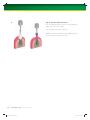
4.3 Placing the implant
A Straumann® implant can be placed either manually with the ratchet or with the aid of the handpiece. A maximum
speed of 15 rpm is recommended. The following step-by-step shows how a Straumann® Standard Plus Implant is
placed with the handpiece (left column on the following pages) and how a Straumann® Bone Level Implant is placed
with the ratchet (right column).
Note
Straumann® Bone Level implants must be rotationally oriented for both, handpiece and ratchet insertion (see Step 5 on
page 47). Apart from this exception, all Straumann® implants are placed in the same way.
Placement with the handpiece
Example: Straumann® Standard Plus Implant
1
Placement with the ratchet
Example: Straumann® Bone Level Implant
1
“click”
Step 1 – Attach the handpiece adapter
Grasp the closed part of the implant carrier. Attach the
handpiece adapter to the implant. A click is heard when
the handpiece adapter is attached correctly.
44
4. Surgical procedures
122461_15X.754.indd Abs1:44
Step 1 – Attach the ratchet adapter
Hold the implant carrier at the closed end and push the
ratchet adapter onto the transfer part until you hear a
click.
4.3 Placing the implant
17.9.2007 9:49:17 Uhr
2
2
Step 2 – Remove the implant from the carrier
Simultaneously, pull down the implant carrier and lift the
implant out of the implant carrier (while supporting your
arms).
Step 2 – Remove the implant from the carrier
Pull the implant carrier slightly downward to remove the
implant from the implant carrier. At the same time, lift the
implant from the carrier with a slight twisting movement
(prop your hands while doing this).
3
3
Step 3 – Place the implant
Place the implant with the handpiece into the implant
bed.
Step 3 – Place the implant
Place the implant manually into the implant bed with the
aid of the adapter.
4. Surgical procedures
122461_15X.754.indd Abs1:45
4.3 Placing the implant
45
17.9.2007 9:49:20 Uhr
4
4
4 mm
Step 4 – Insert the implant with the handpiece
Move the implant into final position with a maximum of
15 rpm, turning it clockwise.
Note
When the floor of the bone cavity is reached, there is a
palpable increase in resistance.
Step 4 – Insert the implant with the ratchet
Attach the ratchet and the pivot of the holding key which
is used for stabilizing. The clockwise arrow on the rotary
knob signals the direction of insertion (see insert). Bring
the implant into its final position at bone level with slow
movements of the ratchet.
The top 4 mm cylindrical part of the transfer part for
Straumann® Bone Level implants can be used as a depth
indicator (e.g. relative to the prospective gingival margin).
It facilitates coronoapical implant positioning in the anterior area.
Caution
Insertion torque should not exceed 35 Ncm. To prevent bone compression, check for correct implant bed preparation
when reaching 35 Ncm before the implant is in its final position.
To avoid bone damage (bone necrosis or bone splitting) in the event of incorrect use (e.g. excessive tightening
resistance with an inadequate drilling depth), the transfer part is provided with a breaking point. If the transfer part
breaks during the tightening process, part of the transfer screw remains in the adapter and the other part in the
implant. The part in the implant can be easily unscrewed with the aid of a forceps. For this eventuality, it is advisable
to keep a used sterile transfer part in stock.
46
4. Surgical procedures
122461_15X.754.indd Abs1:46
4.3 Placing the implant
17.9.2007 9:49:24 Uhr
5
Step 5 – Not needed for S/SP/TE
S, SP, and TE implants don‘t need to be rotationally
oriented.
If you are placing a Bone Level Implant with the handpiece, choose the correct position as shown in Step 5 in
the right column.
Step 5 – Correct implant orientation
While approaching the final implant position, make sure
that one of the four white marks on the blue transfer part
is exactly oriented orofacially. This positions the four
protrusions of the internal connection for ideal prosthetic
abutment orientation. A quarter turn to the next white mark
corresponds to a vertical displacement of 0,2 mm.
Caution
Avoid vertical position corrections using reverse rotations
(counterclockwise). This can cause loosening of the transfer part and may lead to a decrease in primary stability.
4. Surgical procedures
122461_15X.754.indd Abs1:47
4.3 Placing the implant
47
17.9.2007 9:49:28 Uhr
6
6
Step 6 – Loosen the transfer part
Before removing the transfer part, set the motor on the
handpiece to “reverse”.
Step 6 – Loosen the transfer part
Change the direction of the ratchet. The arrow on the
rotary knob now points counterclockwise (see insert). Use
the holding key to counter the octagon and loosen the
transfer part counterclockwise using the ratchet (for details
of the holding key see page 64).
During the first few turns, hold the implant with the holding
key which is used for stabilizing (countering) the hexagon.
Remove the transfer part (for details of the holding key see
page 64).
48
4. Surgical procedures
122461_15X.754.indd Abs1:48
4.3 Placing the implant
17.9.2007 9:49:33 Uhr
7
7
Step 7 – Remove the instruments
Remove the holding key and then completely remove the
transfer part with the adapter from the implant.
Step 7 – Remove the instruments
Remove the holding key, then the ratchet, while holding
the adapter at the bottom. Finally, remove the transfer
part from the implant with the adapter still mounted completely.
4. Surgical procedures
122461_15X.754.indd Abs1:49
4.3 Placing the implant
49
17.9.2007 9:49:36 Uhr
4.4 Soft tissue management
After implantation, the implant is closed – hand-tightened – with an SCS closure screw, healing cap or healing abutment
to protect the implant (for SCS screwdrivers see page 64). The surgeon can choose between submucosal and transmucosal healing and has all options available for soft tissue management made possible through a set of secondary
healing components.
The non-epithelialized side of the flap should be approximated to the implant neck (soft tissue approximation).
If necessary, this step must be combined with a gingivectomy. The wound margins are closed with atraumatic suture
material, and the sutures must not be tied too tightly. One relieving suture is placed on either side of the closure
screw or healing cap so that the wound margins are approximated without tension. Use of non-absorbable suture
material is recommended (e.g. Polyamide or Teflon). The sutures are removed after 7–10 days. A postoperative X-ray is
recommended.
4.4.1 Submucosal healing
For submucosal healing (healing under closed mucoperiosteal flap) the use of a closure screw, shorter healing cap or
healing abutment is recommended. Submucosal healing is suggested in esthetic indications and for implantations with
simultaneous guided bone restoration (GBR) or membrane technique. A second surgical procedure is required for uncovering the implant and insertion of the desired secondary component.
1
Step 1 – Inserting the closure screw after 1st surgery
Ensure that the internal configuration of the implant is
clean and bloodless.
Pick up the closure screw with the SCS screwdriver. The
friction fit will secure the closure screw to the instrument
during insertion and will allow safe handling.
Hand-tighten the closure screw. The design will provide a
tight connection between the two components.
Note
Bone Level closure screws are delivered sterile and ready
to use. All other Straumann® closure screws are delivered
non-sterile and must be sterilized prior to use.
Subsequent loosening is made easier by applying
chlorhexidine gel or sterile Vaseline to the closure screw
before it is screwed into the implant.
50
4. Surgical procedures
122461_15X.754.indd Abs1:50
4.4 Soft tissue management
17.9.2007 9:49:38 Uhr
2
Step 2 – Wound closure
Adapt the mucoperiosteal flaps carefully and suture
together with interrupted sutures.
Make sure a tight seal is formed over the implant.
3
Step 3 – Reopening and removal: 2nd surgery
Locate the implant.
Make a small crestal incision down to the closure screw.
Spread the flap slightly and remove the closure screw
with the SCS screwdriver.
4. Surgical procedures
122461_15X.754.indd Abs1:51
4.4 Soft tissue management
51
17.9.2007 9:49:40 Uhr
4
Step 4 – Insertion and wound closure
Rinse the exposed internal connection of the implant thoroughly with sterile saline solution.
Insert a suitable secondary component.
Adapt the soft tissue and suture it back tightly without tension around the secondary component.
52
4. Surgical procedures
122461_15X.754.indd Abs1:52
4.4 Soft tissue management
17.9.2007 9:49:45 Uhr
4.4.2 Transmucosal healing
A versatile portfolio of healing caps and healing abutments is available for all Straumann® implants enabling softtissue sculpturing during transmucosal healing. They are recommended for intermediate use. After the soft-tissue healing
phase they are replaced with the appropriate temporary or final restoration.
1
Step 1 – Insertion
Ensure that the internal configuration of the implant is
clean and bloodless.
Insert the healing cap or healing abutment with the SCS
screwdriver. The friction fit secures the components to the
instrument during insertion and ensures safe handling.
Hand-tighten the healing cap or healing abutment. The
design will provide a tight connection between the two
components.
Note
Healing caps and abutments are delivered non-sterile in
blisters and must be sterilized prior to use.
Subsequent loosening is made easier by applying chlorhexidine gel or sterile Vaseline to the healing cap
or healing abutment before they are screwed into the
implant.
2
Step 2 – Wound closure
Adapt the soft tissue and suture it back tightly around the
abutment.
4. Surgical procedures
122461_15X.754.indd Abs1:53
4.4 Soft tissue management
53
17.9.2007 9:49:46 Uhr
Overview of closure screws and healing caps for Straumann® Standard, Standard Plus,
and Tapered Effect implants
Indication
Connection Article
Submucosal healing
p If submucosal healing is desired, use of
a closure screw or shorter healing cap is
recommended.
Transmucosal healing
p By using a taller healing cap, transmucosal healing can be obtained even
when the implant shoulder is in a subgingival position.
Esthetic region
p The labial bevel facilitates exact approximation of the soft tissue over the healing
cap. Ensure that there is no tension on the
vestibular wound margin, as otherwise
mucosal necrosis can occur.
p To optimise the gingival contour, it is advisable after exposure of the implant (4–6
weeks after implantation) to exchange the
beveled healing cap for a longer healing
cap without bevel (selected according to
mucosal thickness and temporary
restoration).
54
4. Surgical procedures
Art. No.
NN
Closure screw with hex socket,
height 1,8 mm, Ti
048.374
RN
Closure screw, small, Ti
048.371
048.371V4
RN
Closure screw, large, height 1,5 mm, Ti
048.373
048.373V4
WN
Closure screw, Ti
048.375
NN
Protective cap with integral occlusal screw,
Ø 4 mm, height 3,4 mm, polymer/Ti
048.050
NN
Healing cap with integral occlusal screw,
Ø 4 mm, height 3,4 mm, Ti
048.043
RN
Closure screw, large, height 1,5 mm, Ti
048.373
048.373V4
RN
Healing cap, height 2 mm, Ti
048.033
RN
Healing cap, height 3 mm, Ti
048.034
RN
Healing cap, height 4,5 mm, Ti
048.037
WN
Healing cap, height 2 mm, Ti
048.038
WN
Healing cap, height 3 mm, Ti
048.039
WN
Healing cap, height 4,5 mm, Ti
048.053
NN
Healing cap with integral occlusal screw,
Ø 4 mm, height 3,4 mm, Ti
048.043
RN
Healing cap with labial bevel, short,
height 2 mm, Ti
048.028
RN
Healing cap with labial bevel, long,
height 3,5 mm, Ti
048.029
Healing cap with labial bevel,
height 2 mm, Ti
048.030
WN
4.4 Soft tissue management
122461_15X.754_AlleSprachen.inddAbs1:54 Abs1:54
24.9.2007 10:47:26 Uhr
Overview of closure screws and healing abutments for Straumann® Bone Level implants
Indication
Submucosal healing
p For submucosal healing a closure screw
or a short healing abutment should be
used. Use of the H 0,5 mm closure
screw is recommended for deeply placed
implants if bone overgrowth is present.
Transmucosal healing
p The set of healing abutments, which have
profiles matched to secondary components,
allows for simple and reliable soft tissue
management.
Connection
Article
Art. No.
NC
NC Closure Screw, height 0 mm, Ti
024.2100-04*
NC
NC Closure Screw, height 0,5 mm, Ti
024.2105-04*
NC
NC Healing Abutment,
conical, diameter 3,6 mm, height 2 mm, Ti
024.2222
RC
RC Closure Screw, height 0 mm, Ti
024.4100-04*
RC
RC Closure Screw, height 0,5 mm, Ti
024.4105-04*
RC
RC Healing Abutment,
conical, diameter 4,5 mm, height 2 mm, Ti
024.4222
NC
NC Healing Abutment,
conical, diameter 3,6 mm, height 2 mm, Ti
024.2222
NC
NC Healing Abutment,
024.2224
conical, diameter 3,6 mm, height 3,5 mm, Ti
NC
NC Healing Abutment,
conical, diameter 3,6 mm, height 5 mm, Ti
024.2226
NC
NC Healing Abutment,
conical, diameter 4,8 mm, height 2 mm, Ti
024.2242
NC
NC Healing Abutment,
024.2244
conical, diameter 4,8 mm, height 3,5 mm, Ti
NC
NC Healing Abutment,
conical, diameter 4,8 mm, height 5 mm, Ti
024.2246
RC
RC Healing Abutment,
conical, diameter 4,5 mm, height 2 mm, Ti
024.4222
RC
RC Healing Abutment,
conical, diameter 4,5 mm, height 4 mm, Ti
024.4224
RC
RC Healing Abutment,
conical, diameter 4,5 mm, height 6 mm, Ti
024.4226
RC
RC Healing Abutment,
conical, diameter 6 mm, height 2 mm, Ti
024.4242
RC
RC Healing Abutment,
conical, diameter 6 mm, height 4 mm, Ti
024.4244
RC
RC Healing Abutment,
conical, diameter 6 mm, height 6 mm, Ti
024.4246
cont.
* Sterile pack of 4
4. Surgical procedures
122461_15X.754_AlleSprachen.inddAbs1:55 Abs1:55
4.4 Soft tissue management
55
24.9.2007 8:19:49 Uhr
Overview of closure screws and healing abutments for Straumann® Bone Level implants, cont.
Indication
Connection
Esthetic region
NC
NC Healing Abutment, bottle shape,
diameter 3,3 mm, height 3,5 mm, Ti
024.2234
NC
NC Healing Abutment, bottle shape,
diameter 3,3 mm, height 5 mm, Ti
024.2236
RC
RC Healing Abutment, bottle shape,
diameter 4,4 mm, height 4 mm, Ti
024.4234
RC
RC Healing Abutment bottle shape,
diameter 4,7 mm, height 6 mm, Ti
024.4236
NC
NC Healing Abutment,
customizable, diameter 5 mm, polymer
024.2270
RC
RC Healing Abutment,
customizable, diameter 7 mm, polymer
024.4270
p Bottle-shaped healing abutments preshape
the soft tissue by allowing for a slight
excess of mucosa during healing. The
insertion of the final restoration pushes
the formed tissue outward, supporting the
creation of a naturally shaped peri-implant
soft tissue. Make sure that there is no
tension on the wound margin. Otherwise
mucosal necrosis can occur.
p The customizable Healing Abutment allows
for individual soft tissue management.
Note
Do not use customizable healing abutments for longer than 6 months.
56
4. Surgical procedures
Article
Art. No.
4.4 Soft tissue management
122461_15X.754_AlleSprachen.inddAbs1:56 Abs1:56
24.9.2007 8:19:51 Uhr
5. HEALING PHASE
5.1 Healing phase duration
Situation
Healing phase
SLA ®
SLActive
p Good bone quality and adequate bone quantity
p Implants with a diameter of 4,1 mm or 4,8 mm and a Straumann® SLActive/SLA
At least 3–4 weeks
At least 6 weeks
p Cancellous bone quality
p Implants with a diameter of 3,3 mm
p Implants with a Straumann® SLActive/SLA surface length of 6 mm
At least 8 weeks
At least 12 weeks
p Straumann® SLActive/SLA surface is not completely in contact with the bone
p Bone augmentation measures* are necessary
Healing phase corresponding to the
situation
surface length of ≥8 mm
SLActive = Sand-blasted, Large grit, Acid-etched, chemically active and hydrophilic, SLA® = Sand-blasted, Large grit, Acid-etched
* This technique should be employed only by dentists who have adequate experience in the use of augmentation procedures.
5.2 Straumann® SLActive and SLA in comparison
The bone formation process is initiated at an earlier stage with Straumann® SLActive, resulting in significantly earlier
secondary stability and thus risk reduction during the critical healing period.
Total stability with SLA®
Total stability with SLActive
Total stability
Total stability
SLA®
0
1
2
3
4
5
Time (weeks)
6
7
8
Secondary
stability
(new bone)
SLA®
0
5. Healing phase
122461_15X.754.indd Abs1:57
SLActive
SLActive (blue line), SLA® (dotted blue line)
Secondary
stability
(new bone)
Primary
stability
(old bone)
Stability
S. Raghavendra, M. Wood, T.D. Taylor (2005)
Stability
Primary
stability
(old bone)
Stability
dip
1
2
3
4
5
Time (weeks)
6
7
8
5.1 Healing phase duration | 5.2 Straumann ® SLActive and SLA in comparison
57
17.9.2007 9:50:05 Uhr
6. ADDITIONAL INFORMATION ON INSTRUMENTS
6.1 Surgical instruments
Instruments must be checked for completeness and function. An adequate
stock of implants and spare sterile instruments should always be available.
The instruments must be disassembled for sterilization. Well maintained
instruments prevent infections from developing that could endanger patients as
well as the practice team.
To avoid contamination of the operation field, all of the instruments and material employed must be sterile. To prevent contamination of the sterile instruments, they should be removed from the surgical cassette with a sterile forceps
and put into the handle or ratchet. The forceps (Art. No. 046.110) was
developed and shaped specially to allow round instruments to be gripped
securely.
Forceps
All steps related to the maintenance of Straumann® surgical instruments are
part of a dental practice hygiene plan (see also “Care and maintenance of
surgical and prosthetic instruments” (Art. No. 152.008).
6.1.1 Depth marks on Straumann® instruments
Straumann® instruments have depth marks in 2 mm intervals that correspond to the available implant lengths.
The marks on twist drills are continuous between 10 mm
and 12 mm. The lower edge of the mark corresponds to
10 mm and the upper edge to 12 mm.
Example: The preparation depth for a 10 mm SP implant
inserted up to shoulder level must be 12 mm.
mm
mm
mm
mm
10 mm
1.
2.
3.
1. Pilot drill 1, Ø 2,2 mm
2. Alignment pin, Ø 2,2 mm
3. Pilot drill 2, Ø 2,8 mm
4. Twist drill, Ø 3,5 mm
5. Twist drill PRO, Ø 4,2 mm
4.
5.
6.
7.
6. Straumann® Standard Plus Implant,
Ø 4,1 RN, length 10 mm
7. Straumann® Bone Level Implant,
Ø 4,1 RC, length 10 mm
max. 0.4 mm
When inserting a Straumann® Standard Plus or Tapered
Effect Implant up to the implant shoulder level (see Preoperative Planning on page 21), the preparation depth must
be 2 mm more than the indicated implant length.
12 mm
12
10
8
6
Due to the function and design of the drills, the drill tip is
0,4 mm longer than the insertion depth of the implant
(see also page 26 on X-ray templates).
Additional length of the drill tip
58
6. Additional information on instruments
122461_15X.754.indd Abs1:58
6.1 Surgical Instruments
17.9.2007 9:50:06 Uhr
6.1.2 Single-patient pilot and twist drills
Like multi-use drills, single-patient drills are indicated for
the preparation of the implant bed for Straumann® Dental
Implants. They are supplied sterile and are to be used
for one operation only and for one patient only. Singlepatient drills can minimize the risk of infection for the
patient. They are color-coded for easy identification of the
diameter width.
Collar for drill
stop mounting
Due to the function and design of the drills, the drill tip
is 0,4 mm longer than the insertion depth of the implant.
New generation single-patient drills are drill stop
compatible. They can be ordered using separate article
numbers.
Single patient drill, drill stop compatible (with collar for drill stop
mounting)
6.1.3 Straumann® Drill Stop – Precise depth
control
The Straumann® Drill Stop provides precise control over
drilling depth during implant bed preparation for the
placement of Straumann® dental implants. Delivered in
sterile sets the drill stops are ready to use. The Straumann®
Drill Stop is designed for single-patient use only
and must be used in conjunction with the single-patient
drills specifically designed for them.
Each Straumann® Drill Stop Set includes drill stops with
the following diameters:
Ø 2,2 mm (blue), Ø 2,8 mm (yellow), Ø 3,5 mm (red),
Ø 4,2 mm (green). These diameters correspond to the
diameters of the Straumann® drills.
Ø 2,2 mm
Ø 2,8 mm
Ø 3,5 mm
Ø 4,2 mm
Drill Stop Set for one depth
6. Additional information on instruments
122461_15X.754.indd Abs1:59
6.1 Surgical Instruments
59
17.9.2007 9:50:09 Uhr
Straumann® Drill Stop reference chart
Short drill
Long drill
Drill stop type
Implant bed
depth
16 mm
14 mm
12 mm
10 mm
8 mm
6 mm
Drill stop type
A
B
C
D
A
B
C
D
Note
Straumann® drill stops are not indicated for:
p Extraction sites, where bone cavity is often wider than the diameter necessary to hold the drill stop.
p Use with drill templates, due to the interference from or with the template.
For more information of the Straumann® Drill Stop please refer to the brochure “Straumann® Drill Stop:
Precise depth control” (Art. No. 152.053).
60
6. Additional information on instruments
122461_15X.754.indd Abs1:60
6.1 Surgical Instruments
17.9.2007 9:50:13 Uhr
6.1.4 Straumann® Surgical Cassette
The surgical cassette is used for the secure storage and sterilisation of the
surgical instruments and auxiliary instruments of the Straumann® Dental Implant
System. The cassette is made of a highly shock-proof thermoplastic, which
has been proven for years in the medical area and is suitable for frequent
sterilisation in the autoclave. Autoclaving at a temperature of up to 134 °C
(273 °F) is recommended.
Screw container
Color coding:
Green = Endosteal implant diameter 4,8 mm
Red = Endosteal implant diameter 4,1 mm
Yellow = Endosteal implant diameter 3,3 mm
p The easy-to-read user guide ensures a reliable working sequence through
color-coded arrows and silicon sleeves.
p Clear illustrations and drill length stops allow the arranged instruments,
screws and healing caps to be checked at a glance for correctness and
completeness.
p The instruments are positioned securely in the silicone sleeves for sterilisation and storage.
p The cassette can be packed according to the working procedure (using the
handpiece or manually with the ratchet).
p The surgical cassette also houses a separate screw container in which
the required Straumann® synOcta and Narrow Neck closure screws and
healing caps are arranged, thus providing ease of access to them.
CrossFit™ healing abutments for the Straumann® Bone Level Implant are
stored separately.
6. Additional information on instruments
122461_15X.754.indd Abs1:61
6.1 Surgical Instruments
61
17.9.2007 9:50:15 Uhr
Guidelines for the sterilisation of the surgical cassette
Method
Temperature
Exposure Time
Dry Time
Steam Sterilization Prevacuum Cycle
134 °C/273 °F
min. 4 – 18 min
20 – 60 min*
Steam Sterilization Gravity Cycle
134 °C/273 °F
min. 40 min
20 – 60 min*
No dry heat sterilization!
* Instruments that are not thoroughly dried may corrode.
Before sterilisation, the cassette is packed (e.g. sealed in foil or wrapped in towels) in order to keep it sterile.
Important
p Chemical sterilisation is not recommended!
p Do not use dry heat sterilisation
p Ensure that the individual sterilisation parameters comply with the current
regulations of the respective country.
In order to avoid damaging the surgical cassette during autoclaving, it must
be placed correctly in the autoclave (see fig.).
See also DVD “Straumann® Dental Implant System – Surgical“, Art. No. 150.541, “Surgical cassette“.
62
6. Additional information on instruments
122461_15X.754.indd Abs1:62
6.1 Surgical Instruments
17.9.2007 9:50:29 Uhr
6.1.5 Ratchet
Ratchet
Service instrument
Ratchet disassembled
The ratchet of the Straumann® Dental
Implant System is a two-part lever
arm instrument with a rotary knob for
changing the direction of force.
The ratchet is supplied with a service
instrument, which is used to loosen
the headed screw.
After loosening, the ratchet bolt can
be removed from the body of the
ratchet. It must be disassembled for
cleaning and sterilisation.
The ratchet is required for the following operations:
p manual thread tapping
p manual placement of implants into
their final position in the implant
bed
6. Additional information on instruments
122461_15X.754.indd Abs1:63
6.1 Surgical Instruments
63
17.9.2007 9:50:29 Uhr
6.1.6 Holding key
The holding key is used for
p stabilizing the ratchet.
p countering the transfer part.
Holding key
Stabilizing the ratchet
Use the pivot of the holding key to stabilize the ratchet
during implant insertion or during tapping.
Stabilizing the ratchet
Countering the transfer part
Use the holding key for countering when loosening the
transfer part from the implant. The transfer part should
be loosened only with the ratchet or handpiece (counterclockwise).
The shape of the holding key is specially designed for
different oral situations
p Forked end: when spaces are normal, the forked end
is attached directly to the hexagon.
p Closed end: when the interdental space is limited, the
closed end must be placed on the hexagon over
the transfer part. To do this, the ratchet and adapter
or handpiece must be removed.
Forked end
Closed end
SCS screwdriver for manual use
Article: extrashort, short, long
Lengths: 15 mm, 21 mm, 27 mm
Material: stainless steel
SCS screwdriver for mechanical use
in the handpiece
Article: extrashort, short, long
Lengths: 20 mm, 26 mm, 32 mm
Material: stainless steel
6.1.7 SCS screwdrivers
64
6. Additional information on instruments
122461_15X.754.indd Abs1:64
6.1 Surgical Instruments
17.9.2007 9:50:30 Uhr
6.2 Osteotomes
6.2.1 Instrument set for bone condensation
p Indicated in cases with cancellous bone (bone class 3 and 4).
p Reinforces bone radially to give improved primary stability to the implant.
Note
The instruments with diameters of 2,2 mm, 2,8 mm, 3,5 mm and 4,2 mm
match the implant diameters of the Straumann® Dental Implant System.
They are available as a straight or angled model, which facilitates access in
the posterior region.
Osteotomes for bone condensation
6.2.2 Instrument set for transalveolar sinus floor elevation
Indicated in cases with inadequate vertical bone. By tapping on the osteotomes with a mallet, the sinus floor can be fractured and elevated.
Note
The instruments with diameters of 2,2 mm, 2,8 mm, 3,5 mm and 4,2 mm
match the implant diameters of the Straumann® Dental Implant System.
They are available as a straight or angled model, which facilitates access in
the posterior region.
Osteotomes for sinus floor elevation
6.2.3 Depth stops for osteotomes
All osteotomes have clear laser marks for depths of 6 mm, 8 mm, 10 mm,
12 mm and 14 mm. In addition, adjustable depth stops facilitate depth
checking.
Further references regarding use in the instructions for use
“Straumann® Osteotomes“ (Art. Nos. 150.855 and 150.857).
See also DVD “Straumann® Dental Implant System–Surgical“
(Art. No. 150.541).
Depth stops for osteotomes
6. Additional information on instruments
122461_15X.754.indd Abs1:65
6.2 Osteotomes
65
17.9.2007 9:50:34 Uhr
6.3 Cleaning and care of instruments
Dimensions
Number of surgical procedures
1
Round bur
044.022
2
3
4
5
6
7
8
9
10
Ø 1.4 mm
Round bur
044.003
Ø 2.3 mm
Round bur
044.004
Ø 3.1 mm
Pilot drill 1
044.210
Ø 2.2 mm, short
Pilot drill 1
044.211
Ø 2.2 mm, long
Pilot drill 2
044.214
Ø 2.8 mm, short
Pilot drill 2
044.215
Ø 2.8 mm, long
Twist drill
044.218
Ø 3.5 mm, short
Twist drill
044.219
Ø 3.5 mm, long
Twist drill PRO
044.254
Ø 4.2 mm, short
Twist drill PRO
044.255
Ø 4.2 mm, long
SP Profile drill, RN
044.086
Ø 2.8 mm, short
SP Profile drill, RN
044.087
Ø 2.8 mm, long
SP Profile drill, RN
044.088
Ø 3.5 mm, short
SP Profile drill, RN
044.089
Ø 3.5 mm, long
SP Profile drill, WN
044.084
Ø 4.2 mm, short
SP Profile drill, WN
044.085
Ø 4.2 mm, long
TE Profile drill, RN
044.701
Ø 2.8 mm, short
TE Profile drill, RN
044.708
Ø 2.8 mm, long
TE Profile drill, RN
044.705
Ø 3.5 mm, short
TE Profile drill, RN
044.712
Ø 3.5 mm, long
TE Profile drill, WN
044.703
Ø 4.2 mm, short
TE Profile drill, WN
044.710
Ø 4.2 mm, long
BL Profile drill
026.2303
Ø 3.3 mm, short
BL Profile drill
026.2306
Ø 3.3 mm, long
BL Profile drill
026.4303
Ø 4.1 mm, short
BL Profile drill
026.4306
Ø 4.1 mm, long
BL Profile drill
026.6303
Ø 4.8 mm, short
BL Profile drill
026.6306
Ø 4.8 mm, long
S/SP Tap for Ratchet
044.590
Ø 3.3 mm, short
S/SP Tap for Ratchet
044.591
Ø 3.3 mm, long
S/SP Tap for Adapter
044.575
Ø 3.3 mm
S/SP Tap for Ratchet
044.592
Ø 4.1 mm, short
S/SP Tap for Ratchet
044.593
Ø 4.1 mm, long
S/SP Tap for Adapter
044.577
Ø 4.1 mm
S/SP Tap for Ratchet
044.594
Ø 4.8 mm, short
S/SP Tap for Ratchet
044.595
Ø 4.8 mm, long
S/SP Tap for Adapter
044.579
Ø 4.8 mm
BL/TE Tap for Adapter
026.2310
Ø 3.3 mm
BL/TE Tap for Adapter
026.4310
Ø 4.1 mm
BL/TE Tap for Adapter
026.6310
Ø 4.8 mm
B00907
Art. No.
07/07 152.755/e
*Exception: “Single-patient drills“ (see
page 59).
SURGERY TRACKING SHEET FOR STRAUMANN CUTTING INSTRUMENTS
Article
Straumann products are CE marked
Careful treatment of all instruments is
of the utmost importance. Even slight
damage for instance to the drill tips
(e.g., when the drills are “thrown”
into a bowl of water) impairs cutting
performance and thus the clinical
result. With correct and careful care,
the high quality of the material and
excellent workmanship ensure that
the rotating instruments (drills*, taps
etc.) can be used repeatedly (up to
a maximum of ten times is recommended). The “Surgery tracking sheet
for Straumann cutting instruments“
(Art. No. 152.755) helps to give an
overview of how often the individual
instruments have already been used.
Note Because Straumann drills and taps are precisely manufactured and made of high quality material, they can be used in up to 10 surgical procedures. However,
careful handling and cleaning techniques are essential to maintain correct function (refer to “Care and maintenance of surgical and prosthetic instruments”).
For additional information visit www.straumann.com
66
6. Additional information on instruments
122461_15X.754.indd Abs1:66
6.3 Cleaning and care of instruments
18.9.2007 8:16:38 Uhr
Instruments with high cutting performance are a basic
requirement for successful implantation. The following
should therefore be remembered:
p Never allow instruments to land on their tips.
p Every instrument must be used only for its particular
intended purpose.
p Dirty instruments should be placed in a bowl of Ringer‘s solution (avoid allowing blood or tissue residue to
dry on them).
p Residues of blood, saliva, tissue or bone must be
removed from the instruments immediately after surgery.
Every piece of residue that adheres to the instruments
and dries on them leads to corrosion.
p Multi-part instruments (e.g., ratchet, internally cooled
trephine drill) must be disassembled for sterilisation and
storage.
p Used instruments must always be placed in a suitable
medium for disinfection prior to cleaning.
p Dirty instruments must be placed only on the intended
surface (cassette lid or appropriate dish).
p Never disinfect, clean (including ultrasonically) or
sterilise instruments made of different materials together.
p Damaged instruments must be sorted, disinfected,
cleaned separately, and discarded.
p Never store instruments damp or wet for prolonged
periods.
You will find detailed information in the brochure “Care
and maintenance of surgical and prosthetic instruments“
Art. No. 152.008.
Ultrasonic Cleaning Cassette
The Ultrasonic Cleaning Cassette ensures optimal storage
during instrument disinfection and cleaning in the ultrasonic bath.
The pimpled silicone mat prevents the cutting edges of the
instruments from coming in contact, which would have a
negative effect on their cutting performance.
6. Additional information on instruments
122461_15X.754.indd Abs1:67
6.3 Cleaning and care of instruments
67
17.9.2007 9:50:36 Uhr
7. APPENDIX
7.1 Labeling and color coding of the Straumann® Dental Implant System
Naming and labeling explanations
Color coding
yellow
Endosteal implant diameter 3,3 mm
red
Endosteal implant diameter 4,1 mm
green
Endosteal implant diameter 4,8 mm
Implant types
S: Standard Implant
SP: Standard Plus Implant
TE: Tapered Effect Implant
BL: Bone Level Implant
Connection types
Ø 3,5 mm
NN: Narrow Neck Ø 3,5 mm
Ø 4,8 mm
RN: Regular Neck Ø 4,8 mm
Ø 6,5 mm
WN: Wide Neck Ø 6,5 mm
Ø 3,3 mm
NC: Narrow CrossFit™ Ø 3,3 mm
Ø 4,1 mm Ø 4,8 mm
RC: Regular CrossFit™ Ø 4,1 and Ø 4,8 mm
68
7. Appendix
122461_15X.754.indd Abs1:68
7.1 Labeling and color coding of the Straumann ® Dental Implant System
17.9.2007 9:50:38 Uhr
Example of label on implant packaging
Connection type
Endosteal diameter
Implant type
Standard Plus Implant
Ø 4.1 mm RN
SLA 8 mm
Length of the SLA /SLActive surface
®
Article number
REF 043.053S
JJJJ-MM
Surface type
LOT number
XXXXX
The Green Dot
0510
940.XXX
128 Barcode
Institut Straumann AG
CH-4002 Basel
Manufacturer
Switzerland
Use before expiration date
Caution: Federal law (US) restricts this
product to sale by or on the order of
a dentist or physician
Single use only
Please read and follow instruction leaflet
Straumann products are CE marked and fulfill the requirements
of the European Medical Devices Directive 93/42 EEC
SP
Ø 3.3 NN
8
Straumann®
Standard Plus Implant
Endosteal diameter 3,3 mm
Narrow Neck
8 mm SLA®
SP
Ø 4.1 RN
SLActive
10
Straumann®
Standard Plus Implant
Endosteal diameter 4,1 mm
Regular Neck
10 mm SLActive
Sterilized with gamma radiation
TE
Ø 4.8 WN
SLActive
12
Straumann®
Tapered Effect Implant
Endosteal diameter 4,8 mm
Wide Neck
12 mm SLActive
7. Appendix
122461_15X.754.indd Abs1:69
BL
Ø 4.1 RC
SLActive
12
Straumann®
Bone Level Implant
Endosteal diameter 4,1 mm
Regular CrossFit™
12 mm SLActive
7.1 Labeling and color coding of the Straumann ® Dental Implant System
69
17.9.2007 9:50:39 Uhr
7.2 Related documentation
Note
Our detailed documentation will help you in carefully
planning and performing your implant-based restorations:
p “Straumann® Narrow Neck”, Art. No. 152.305
p “Crown and Bridge Restorations: Straumann® synOcta
Prosthetic System”, Art. No. 152.255
p “Cement-retained crowns and bridges with the solid
abutment system: Straumann® Solid Abutment Prosthetic
System”, Art. No. 152.254
p “Straumann® Osteotomes”, Art. No. 150.855 and
150.857
p “Straumann® Bone Level Implant line: Basic information
on the prosthetic procedures”, Art. No. 152.810
The DVD “Straumann® Dental Implant System–Surgical“,
Art. No. 150.541, features the following films:
p Measurement and analysis procedure for operation
planning
p Implantation of a Standard Plus implant
p Implantation of a Tapered Effect implant
p Surgical cassette
p Osteotomes
Instrument care and maintenance
Well maintained instruments are a basic requirement for
successful treatment. You will find detailed information
in the brochure “Care and maintenance of surgical and
prosthetic instruments“ Art. No. 152.008.
The Straumann® guarantee
As a Swiss company, we attach the greatest importance
to manufacturing our products in to the highest quality.
We are firmly convinced of the scientific and clinical
basis of our Straumann® Dental Implant System and draw
on the fund of know-how from nearly 30 years of quality
production. The Straumann guarantee regulates replacement of all components of the Straumann® Dental Implant
System. You will find detailed information in the brochure
“The Straumann guarantee“ Art. No. 152.360.
Explantation
For explantation guidelines please refer to the “Directions
for use: Explantation procedure for Straumann® dental
implants”, Art. No. 150.854. The components required
for explanation can be found in our current product catalogue.
References
The Straumann® Dental Implant System has been comprehensively clinically documented for over 25 years. You
can find references to the current research literature on our
website www.straumann.com or by contacting your local
Straumann representative.
Courses and training
Continuing education ensures long-term success! Please,
ask your Straumann representative directly for information
on the Straumann® Dental Implant System courses and
training. Further information at www.straumann.com.
70
7. Appendix
122461_15X.754.indd Abs1:70
7.2 Related documentation
17.9.2007 9:50:41 Uhr
Custom-made products
Under certain circumstances, custom-made products can
be supplied for special indications or cases that cannot
be treated with standard products.
A custom-made product is defined according to EEC
directive 93/42/EEC (Article 1, section d) as being
any product fabricated specifically for a named patient
according to specific characteristics and prescribed
in writing by an appropriately qualified doctor, who
assumes the responsibility.
If you require a custom-made product, please contact
your customer service.
Quality assurance in accordance with MDD 93/42/EEC
All production stages carried out by Institut Straumann AG
are subject to the Standards laid down in the EN ISO 9001
quality assurance system. This European standard
establishes in detail the criteria which a company must
fulfil regarding comprehensive quality assurance during its
manufacturing processes in order to be recognized.
Particularly high standards are rightly expected of medical
products. They are defined in European standards ISO
13485, which we also meet. This ensures that the quality of our products and services meets our customers‘
expectations, and can be reproduced and traced at any
time. Our products comply with the essential requirements
defined in the Medical Devices Directive 93/42/EEC.
All of our medical products therefore carry the CE mark.
Institut Straumann AG meets the stringent requirements of
European directive MDD 93/42/EEC for medical devices
and standards EN ISO 9001 and ISO 13485.
List of abbreviations
SCS
=
Screw Carrying System
HDD
=
Horizontal Defect Dimension
SLActive
=
Sand-blasted, Large grit, Acid-etched,
chemically active and hydrophilic
SLA®
=
Sand-blasted, Large grit, Acid-etched
NN
=
Narrow Neck (3,5 mm)
RN
=
Regular Neck (4,8 mm)
WN
=
Wide Neck (6,5 mm)
NC
=
Narrow CrossFit ® Connection
(for BL implants)
RC
=
Regular CrossFit ® Connection
(for BL implants)
S
=
Standard
SP
=
Standard Plus
TE
=
Tapered Effect
BL
=
Bone Level
7. Appendix
122461_15X.754.indd Abs1:71
7.2 Related documentation
71
17.9.2007 9:50:41 Uhr
7.3 Important notes
Disclaimer of liability
The Straumann dental implant is part of an overall concept and
may only be used in conjunction with the associated original
components and instruments according to Institut Straumann AG’s
instructions and recommendations.
Explanation of the symbols on labels and instruction leaflets
Lot/batch number
Article number
Use of products made by third parties in conjunction with the
Straumann® Dental Implant System will void any warranty or other
obligation, express or implied, of Institut Straumann AG.
Instructions as to application of our products take place verbally, in
writing, by electronic media or in hands-on trainings corresponding to
state of the art at the time of introduction of the product.
The user of Straumann products has the duty to determine whether or
not any product is suitable for the particular patient and circumstances.
Straumann disclaims any liability, express or implied, and shall have
no responsibility for any direct, indirect, punitive or other damages,
arising out of or in connection with any errors in professional judgment
or practice in the use or installation of Straumann products.
The user is also obliged to study the latest developments of the
Straumann® Dental Implant System and their applications
regularly.
Sterile by gamma irradiation
Nonsterile
Lower temperature limit
…min.
…max.
Upper temperature limit
…max.
Temperature limit
…min.
Please note
The descriptions contained in this document are not sufficient for
immediate use of the Straumann® Dental Implant System. Knowledge
of dental implantology and instruction in the handling of the
Straumann® Dental Implant System provided by an operator with the
relevant experience are always necessary.
Caution: Federal (USA) law restricts this
product to sale by or on the order of a
dentist or physician
Do not use on patients
Availability
Not all products listed in this brochure are available in all countries.
Do not reuse
Validity
Upon publication of this brochure, all previous versions are superseded.
Refer to instructions for use
Caution
Our products must be secured against aspiration when used intraorally.
Do not use damaged or blunt instruments.
Use before expiry date
Units per package
Unless stated otherwise, there is one unit in each package.
Documentation
You can obtain detailed instructions on the Straumann® Dental Implant
System from your Straumann representative.
Copyright and trademarks
Straumann documents may not be reprinted or published, in whole
or part, without the written authorization of Institut Straumann AG.
Straumann® and/or other products and logos from Straumann®
that are mentioned here are trademarks or registered trademarks of
Straumann Holding AG and/or its affiliates.
Definition SLActive
Sand-blasted, Large grit, Acid-etched, chemically active and
hydrophilic
Definition SLA®
Sand-blasted, Large grit, Acid-etched
72
7. Appendix
Protect from exposure to strong light or heat
XXXX
Straumann products carry the CE mark and
fulfill the requirements of the Medical Devices
Directive 93/42 EEC
Consult operating instructions
Colored warning labels
YELLOW = CAUTION
Indicates hazards or unsafe handling
which might cause minor injury or
damage to property
ORANGE = WARNING
Indicates hazards which might cause
serious or fatal injury
RED = DANGER
Indicates hazards which might cause
immediate serious or fatal injury
7.3 Important notes
122461_15X.754_AlleSprachen.inddAbs1:72 Abs1:72
24.9.2007 16:12:38 Uhr
8. INDEX
axial orientation
biological principles
bone
availability
augmentation
class
condensation
damage
effective availability
formation process
quality
quantity
Bone Control Design™
buccal wall
cemento-enamel-junction
color-coded
contraindications
contralateral
coronal
coronoapical
CrossFit™ Connection
dental practice hygiene plan
depth marks
depth stops
Diagnostic T
drill template
custom made
free end situations
single tooth gaps
vacuum formed
drilling depth
endosteal diameters
full depth tapping
healing phase duration
holding key
hydrophilic properties
implant
diameter
distance indicator
insertion depth
orofacial
position
shoulder diameter
specific indications
Straumann® Bone Level
Straumann® Standard
Straumann® Standard Plus
Straumann® Tapered Effect
indications
insertion depth
instrumentation
instruments
lingual/palatinal wall
mesial/distal point
minimum guidelines
Morse taper connection
osteotomes
15
3
25, 32
57
39
65
46
27
57
57
57
3
22
21
59
10
21
36
21
8
58
58
65
18, 23
28
29
29
28
59
3
36
57
48, 64
9
15
24
27
20
15, 32
23
11
6
6
6
6
10
59
35
34, 58
22
22
15
7
65
8. Index
122461_15X.754_AlleSprachen.inddAbs1:73 Abs1:73
73
24.9.2007 8:19:52 Uhr
pilot drill
preparation
implant bed
basic
fine
preparation depth
profile drilling
ratchet
reconstruction
prosthetic
reference sphere diameter
risk of infection
minimize
SCS screw driver
single tooth gap
single-patient drill
new generation
sinus floor elevation
SLA® surface
Standard Implant
Straumann® Dental Implant System
Straumann® Drill Stop
Straumann® Drill Stop Set
Straumann® SLA
Straumann® SLActive
Straumann® Surgical cassette
superstructure
surfaces
surgical kit
synOcta® connection
tapered effect
tapping
template
vacuum-formed
transfer part
Twist Drill PRO
twist drill
wax-up/set-up
X-ray
distortion
templates
X-ray reference sphere
74
32
31
31
35
58
35
63
23
26
59
64
17
59
65
9, 57
21
3
59
59
9, 57
9, 57
61
15
9
3, 30
7
21
36
28
46
33
58
15
26
26
25
8. Index
122461_15X.754.indd Abs1:74
17.9.2007 9:50:43 Uhr
NOTES
122461_15X.754.indd Abs1:75
17.9.2007 9:50:44 Uhr
NOTES
122461_15X.754.indd Abs1:76
17.9.2007 9:50:44 Uhr
122461_15X.754.indd bz
09/07 152.754/e
B00907
International Headquarters
Institut Straumann AG
Peter Merian-Weg 12
CH-4002 Basel, Switzerland
Phone +41 (0)61 965 11 11
Fax
+41 (0)61 965 11 01
Straumann products are CE marked
w ww.strau m an n .c o m
17.9.2007 9:50:44 Uhr