1
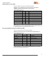
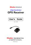
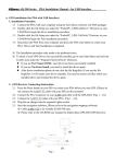
AQ-300-U
High Sensitivity
GPS Receiver
User’s Manual Guide
AQ Max Technology Inc.
6F-2, No.90, Sec. 1, Chung-Hwa East Road., Tainan 701, Taiwan, R.O.C.
Tel: 886-6-2380861 Fax: 886-6-2380853
E-MAIL: [email protected] Web: www.AQmax.com
All Right Reserved
AQ-300 Operating Manual
Contents
Quick Use
Turn on your machine............................................................................3
Check Connector………………………………………………….…...……3
Connect AQ-300 to your machine……………………………….…...……3
Turn on your machine……………………………………………………….3
Introduction
Overview……………………………………………………………………...4
Features………………………………………………………………………4
Technical Specifications…………………………………………………….5
Operational
Characteristics
Hardware Interface
Dimension…………………………………………………………….…..…..7
Hardware Interface……………………………………………………..……7
Connector……………………………………………………………………..7
Accessories…………………………………………………………..………8
USB Driver
System Requirement…………………………………..…...………..…….10
Installation…………………………………………………………….…….10
Important…………………………………………………………….…….. 10
…………………………………………………………………………..……11
Waranty
Appendix A
Software Inferface
Appendix B
Earth Datums
Output Setting
Initialization………………………………………………………………...…6
Navigation…………………………………………………………..……......6
NMEA Transmitted Sentences……………………………………….…...12
RTCM Received Data………………………………………………….…..15
and
Accessories…………………………………………………………………16
Product Combination………………………………………………………16
Appendix C
Products Information
Earth Datums……………………………………………………………….17
Setting……………………………………………………………………….17
2
AQ-300 Operating Manual
Quick Use
Check GPS Package
Standard Package
Optional Package
Check connector
AQ-300 (GPS Receiver) + CD + Warranty Card + Quick Use
The shop may bundle different accessories for you as follows:
1. PC Cable
2. PDA Cable
3. PDA Holder
4. Software (Navigation Software + Digital Map)
5. Others
a. C3000 RS-232 Serial Port Connector
b. C3001 USB Connector, please install USB driver first.
c. When you connect your PDA to GPS-6010, you need an optional cable.
Check the e mark (FCC) for safety and ensure the cigarette adapter
with correct model number to avoid damaging your PDA.
d. Various cables are ready for optional devices.
Connect AQ-300 to your machine.
Turn on your machine.
Your AQ-300 starts to provide you full GPS function.
3
AQ-300 Operating Manual
Introduction
Overview
Features
The AQ-300 Smart Antenna is a total solution GPS receiver, designed
based on SiRF Star II Architecture. The AQ Max GPS technology is a low
power (32mA), cost effective and easy integration GPS system. This
positioning application meets strict needs such as car navigation,
mapping, surveying, security, agriculture and so on.
Only clear view of sky and certain power supply are necessary to the unit.
It communicates with other electronic utilities via compatible dual-channel
through RS-232 or TTL and saves critical satellite data by built–in backup
memory. With low power consumption, the AQ-300 tracks up to 12
satellites at a time, re-acquires satellite signals in 100 ms and updates
position data every second. The following sleeping mode will save power
consumption dramatically to allow critical low power applications.
The AQ-300 provides a host of features that make it easy for integration
and use.
1. SiRF Star II chipset with embedded R3000 level, MIPS I class, 32-bit
RISC processor available for customized applications in firmware.
2. High performance receiver tracks up to 12 satellites while providing
first fast fix and low power consumption.
3. Differential capability utilizes real-time RTCM corrections producing
1-5 meter position accuracy.
4. Compact design ideal for applications with minimal space.
5. A rechargeable battery sustains internal clock and memory. It is
recharged during normal operation.
6. User initialization is not required.
7. Dual communication channels and user selectable baud rates allow
maximum interface capability and flexibility.
8. Optional communication levels, RS-232 and TTL meet ordinary
application and new fashions of connecting PDA with TTL or RS-232
output.
9. FLASH based program memory: New software revisions upgradeable
through serial interface.
10. LED display status: The LED provides users visible positioning status.
LED “ON” when power connected and “BLINKING” when GPS-6010
position identified. No more extra device is needed.
11. Built-in WAAS demodulator.
12. Built-in magnets for using on top of the car.
13. Waterproof (1 meter) design for all weather.
4
AQ-300 Operating Manual
Technology
specifications
Physical Dimension
Single construction integrated antenna/receiver.
59.8(W) x 47.6(D) x 21.4(H) (mm)
2.35"(W) x 1.87"(D) x 0.84"(H) (inch).
Size:
Environmental
Characteristics
Operating temperature:
Storage temperature:
Electrical
Characteristics
Input voltage:
Backup power:
Performance
Tracks up to 12
satellites.
-40oC to +85oC (internal temperature).
-55oC to +100oC.
+4.75 ~ 5.5 VDC without accessories.
+6 ~ 30VDC with accessory C3004.
3V Rechargeable Lithium cell battery, up to 767 hours (31.9 days)
discharge.
Update rate:
1 second.
Reacquisition
0.1 sec., averaged
8 sec., averaged
38 sec., averaged
45 sec., averaged
Acquisition time
Hot start
Warm start
Cold start
Position accuracy:
Non DGPS
(Differential GPS)
Position
Velocity
Time
DGPS
(Differential GPS)
Position
Velocity
Dynamic Conditions:
Altitude
Velocity
Acceleration
Jerk
Interfaces
5-25 meter CEP with SA off
0.1 meters/second, with SA off
1 microsecond synchronized GPS time
1 to 5 meter, typical
0.05 meters/second, typical
18,000 meters (60,000 feet) max
515
meters / second (1000 knots) max
4 G,
max
20
meters/second, max
a. Dual channel RS-232 or TTL compatible level, with user selectable
baud rate (4800-Default, 9600, 19200, 38400).
b. NMEA 0183 Version 2.2 ASCII output (GPGGA, GPGLL, GPGSA,
GPGSV, GPRMC, GPVTG).
c. Real-time Differential Correction input (RTCM SC-104 message types
1, 5 and 9).
d. SiRF protocol.
5
AQ-300 Operating Manual
Operational
characteristics
Initialization
As soon as the initial self-test is complete, the AQ-300 begins the
process of satellite acquisition and tracking automatically. Under normal
circumstances, it takes approximately 45 seconds to achieve a position
fix, 38 seconds if ephemeris data is known. After a position fix has been
calculated, information about valid position, velocity and time is
transmitted over the output channel.
The AQ-300 utilizes initial data, such as last stored position, date, time
and satellite orbital data, to achieve maximum acquisition performance.
If significant inaccuracy exists in the initial data, or the orbital data is
obsolete, it may take more time to achieve a navigation solution. The
AQ-300 Auto-locate feature is capable of automatically determining a
navigation solution without intervention from the host system. However,
acquisition performance can be improved when the host system
initializes the AQ-300 in the following situation:
1) Moving further than 1,500 kilometers.
2) Failure of data storage due to the inactive internal memory battery.
Navigation
After the acquisition process is complete, the AQ-300 sends valid
navigation information over output channels. These data include:
1) Latitude/longitude/altitude
2) Velocity
3) Date/time
4) Error estimates
5) Satellite and receiver status
The AQ-300 sets the default of auto-searching for real-time differential
corrections in RTCM SC-104 standard format, with the message types 1,
5, or 9. It accomplishes the satellite data to generate a differential
(DGPS) solution. The host system, at its option, may also command the
AQ-300 to output a position whenever a differential solution is available.
6
AQ-300 Operating Manual
Hardware interface
Dimension
Size:
Hardware Interface
Connector
Standard cable:
59.8(W) x 47.6(D) x 21.4(H) (mm)
2.35"(W) x 1.87"(D) x 0.84"(H) (inch)
The AQ-300 includes an antenna in a unique style waterproof gadget.
Simply connect PS-2 female connector to one of the optional accessories
and link to either your notebook PC, PDA or other devices. The one-piece
cigarette adapter allows you to connect AQ-300 to your PDAs. Optional
color, input voltage and output connector are listed and described below:
2 meters with female PS-2 connector.
The AQ-300 is also equipped with optional customized connectors.
Function definition of standard PS-2 composite connector
Pin
Signal
1
2
3
4
5
6
Tx (RS-232)
+5VDC
Tx (TTL)
Ground
Rx (TTL)
Rx (RS-232)
7
AQ-300 Operating Manual
Accessories
C3000 Mini Din
Female and PS-2
male connector:
Cable Length:
To AQ-300: 1 meter
RS-232 to PS-2: 45 cm
Mini Din Female connector function definition:
Pin
1
2
3
4
5
6
7
8
9
Signal Name
N.C
Tx
Rx
N.C
Ground
N.C
N.C
N.C
DGPS in
N.C = No connection
PS2 composite connector function definition (to PC):
Pin
Signal Name
1
+5V
2
N.C
3
N.C
4
Ground
5
N.C
6
N.C
N.C = No connection
C3001
USB connector
The function definition of the A Type USB connector is as follows:
Pin
1
2
3
4
Signal Name
+5V
D+
DGround
8
AQ-300 Operating Manual
C3004
High power connector
Color
Black
Red
Green
White
Orange
Signal
Ground
+6~30 VDC
Tx
Rx
DGPS IN
C3002 Optional Cigarette Adapter
The optional cigarette adapter with 2-meter core cable is for using in a car or
boat. It must be used together with a C3000 or an old standard COM + PS-2
GPS receiver.
DC12V - 26V
Input voltage:
CA Cigarette adapter and PDA connector:
Model-No.
CA-ACER
CA-ASUSA600
CA-ASUSA620
CA-BESTA
CA-CASIO E115
CA-CASIO E125
CA-CASIO E200
CA-DELL-X3
CA-DELL-X5
CA-Eten
CA-HandSpring Treo
CA-HandSpring Visor
CA-HandSpring Edge
CA-IPAQ36XX
CA-IPAQ38XX
CA-JORNADA
CA-MIO528NEC
CA-NEC 300E
CA-Palm M5XX
CA-Palm Vx
CA-RS232
CA-Siemens Loox
CA-Siemens SX
CA-SONY-N
CA-SONY-T
CA-SP230(ET180
CA-TOSHIBA e400/800
CA-TOSHIBA e570
CA-TOSHIBA e740
CA-USB
CA-XDA02
PDA/PC
Acer
ASUS
ASUS
BESTA
Casio
Casio
Casio
DELL
DELL
Eten
HandSpring
HandSpring
HandSpring
Compaq
Compaq
HP
MiTAC
ViewSonic
NEC
Palm
Palm/IBM
Siemens
Siemens
SONY
SONY
PDA/PC Model
N10/N20/N20W/S10/S50/S60
A600
A620
I-WINNA
E115
E125/EM500
E200
AXIM-X3
P300
Treo
Visor/Prism
Edge
IPAQ H36XX
IPAQ H38XX/39XX/54XX/22XX/55XX
JORNADA
Mio 528/558/338/339/NEC
V35/V36
NEC 300E
M515/M505/M500/Tungsten T/Zire
Vx
COM PORT
Pocket LOOX
Siemens SX-45
CLIE N/S
CLIE T/NR/SL/ST
Toshiba
Toshiba
Toshiba
e400/e800
e570
e740/e330/e550G
XDA
XDA/02
9
AQ-300 Operating Manual
USB Driver
System
Requirements
Installation
Important
IBM, Pentium or above and other compatible PC; 16 MB and above
memory; Windows 98/Me/2000; VGA Graphic Adapter.
1. Copy entire <AQ-300 USB> folder from CD to hard disk.
2. Connect AQ-300 USB connector to computer. While the computer
automatically starts the installation program, please direct the driver to the
<AQ-300 USB> folder.
3. After the installation is complete, go to <Device Manager> and select
<Ports (COM & LPT)> to verify if a virtual COM port <USB to Serial Port>
was created.
Verify the COM port # to start using your own navigating software.
1. Click <Start> menu, select <Settings>, then enter <Control Panel>.
2. After entering <Control Panel>, select <System>.
3. Select <Device Manager>.
4. Find the <Connect Port> and check the Virtual COM Port, which was
created by the USB driver. Please note that the Virtual COM Port number
might be different from every computer. Before using navigating
software, please confirm the COM Port numbers created by your
computer and provided by your navigation software. They must be the
same Com Port numbers. Otherwise, the navigating software won’t
receive the satellite signal for the un-match COM Port setting.
10
AQ-300 Operating Manual
Warranty
The limited warranty provided by AQ Max Technology Inc. is subject to the
terms set forth below:
1. AQ Max provides certain warranty service to AQ Max Product without
charge for two years warranty period from the purchase date.
2. The warranty for accessories is six months.
3. Repairs or replacement will be made within warranty period at no charge
to the customer either for parts or labor cost. The customer is, however,
responsible for any transportation.
4. Beyond warranty period, parts repair cost and labor cost will be charged.
5. This warranty does not cover any defect due to abuse, misuse, accident
or unauthorized alteration of repairs. AQ Max Technology Inc. assumes
no responsibility for special, incidental, punitive or consequential
damages, or loss of use.
Model number
Series number
Date of Purchase
Name
City, Zip code
State, Country
E-mail
Address
Distributor Stamp Here
11
AQ-300 Operating Manual
Appendix A
Software Interface
NMEA
Transmitted
Messages
The AQ-300 interface protocol is based on the National Marine Electronics
Association's NMEA 0183 ASCⅡinterface specification, which is defined in
NMEA 0183, Version 2.2 and the Radio Technical Commission for Maritime
Services (RTCM Recommended Standards For Differential Navstar GPS
Service, Version 2.1, RTCM Special Committee No.104).
The AQ-300 supported by SiRF Technology Inc. also outputs data in NMEA-0183
format as defined by the National Marine Electronics Association (NMEA),
Standard.
The default communication parameters for NMEA output are 4800 baud, 8 data bits,
stop bit, and no parity.
Table A-1 NMEA-0183 Output Messages
NMEA Sentence
GPGGA
GPGLL
GPGSA
GPGSV
GPRMC
GPVTG
Description
Global positioning system fixed data
Geographic position latitude \ longitude
GNSS DOP and active satellites
GNSS satellites in view.
Recommended minimum specific GNSS data
Course over ground and ground speed
Global Positioning System Fix Data (GGA)
Table A-2 contains the values for the following example:
$GPGGA,161229.487,3723.2475,N,12158.3416,W,1,07,1.0,9.0,M, , , ,0000*18
Table A-2 GGA Data Format
Name
Example
Message ID
$GPGGA
UTC Time
161229.487
Latitude
3723.2475
N/S Indicator
N
Longitude
12158.3416
E/W Indicator
W
Position Fix Indicator
1
Satellites Used
07
HDOP
1.0
MSL Altitude
9.0
Units
M
Geoid Separation
Units
M
Age of Diff. Corr.
Diff. Ref. Station ID
0000
Checksum
*18
<CR> <LF>
Units
Description
GGA protocol header
Hhmmss.sss
ddmm.mmmm
N=north or S=south
dddmm.mmmm
E=east or W=west
See Table 5-3
Range 0 to 12
Horizontal Dilution of Precision
Meters
Meters
Meters
Meters
second Null fields when DGPS is not used
End of message termination
Table A-3 Position Fix Indicator
Value
Description
0
0 Fix not available or invalid
1
GPS SPS Mode, fix valid
2
Differential GPS, SPS Mode, fix valid
3
GPS PPS Mode, fix valid
12
AQ-300 Operating Manual
Geographic Position with Latitude/Longitude (GLL)
Table A-4 contains the values for the following example:
$GPGLL,3723.2475,N,12158.3416,W,161229.487,A*2C
Table A-4 GLL Data Format
Name
Example
Message ID
$GPGLL
Latitude
3723.2475
N/S Indicator
N
Longitude
12158.3416
E/W Indicator
W
UTC Position
161229.487
Status
A
Checksum
*2C
<CR> <LF>
Units
Description
GLL protocol header
ddmm.mmmm
N=north or S=south
dddmm.mmmm
E=east or W=west
hhmmss.sss
A=data valid or V=data not valid
End of message termination
GNSS DOP and Active Satellites (GSA)
Table A-5 contains the values for the following example:
$GPGSA,A,3,07,02,26,27,09,04,15, , , , , ,1.8,1.0,1.5*33
Table A-5 GSA Data Format
Name
Example
Message ID
$GPGSA
Mode 1
A
Mode 2
3
Satellite Used (1)
07
Satellite Used (1)
02
……
Satellite Used
PDOP
1.8
HDOP
1.0
VDOP
1.5
Checksum
*33
<CR> <LF>
(1) Satellite used in solution.
Units
Description
GSA protocol header
See Table 5-6
See Table 5-7
Sv on Channel 1
Sv on Channel 2
….
Sv on Channel 12
Position Dilution of Precision
Horizontal Dilution of Precision
Vertical Dilution of Precision
End of message termination
Table A-6 Mode 1
Value
M
A
Description
Manual—forced to operate in 2D or 3D mode
2D Automatic—allowed to automatically switch 2D/3D
Table A-7 Mode 2
Value
1
2
3
Description
Fix Not Available
2D
3D
13
AQ-300 Operating Manual
GNSS Satellites in View (GSV)
Table A-8 contains the values for the following example:
$GPGSV,2,1,07,07,79,048,42,02,51,062,43,26,36,256,42,27,27,138,42*71
$GPGSV,2,2,07,09,23,313,42,04,19,159,41,15,12,041,42*41
Table A-8 GSV Data Format
Name
Example
Message ID
$GPGSV
Number of Messages
2
Message Number
1
Satellites in View
07
Satellite ID
07
Elevation
79
Azimuth
048
SNR (C/No)
42
....
....
Satellite ID
27
Elevation
27
Azimuth
138
SNR (C/No)
42
Checksum
*71
<CR> <LF>
Units
Description
GSV protocol header
Range 1 to 3
Range 1 to 3
Range 1 to 12
Channel 1 (Range 1 to 32)
degrees Channel 1 (Maximum 90)
degrees Channel 1 (True, Range 0 to 359)
dBHz Range 0 to 99, null when not tracking
Channel 4 (Range 1 to 32)
degrees Channel 4 (Maximum 90)
degrees Channel 4 (True, Range 0 to 359)
dBHz Range 0 to 99, null when not tracking
End of message termination
NOTE: Items <4>,<5>,<6> and <7> repeat for each satellite in view to a maximum of
four (4) satellites per sentence. Additional satellites in view information must be sent
in subsequent sentences. These fields will be null if unused.
Recommended Minimum Specific GNSS Data (RMC)
Table A-9 contains the values for the following example:
$GPRMC,161229.487,A,3723.2475,N,12158.3416,W,0.13,309.62,120598, ,*10
Table A-9 RMC Data Format
Name
Example
Units
Description
Message ID
$GPRMC
RMC protocol header
UTC Time
161229.487
hhmmss.sss
Status
A
A=data valid or V=data not valid
Latitude
3723.2475
ddmm.mmmm
N/S Indicator
N
N=north or S=south
Longitude
12158.3416
dddmm.mmmm
E/W Indicator
W
E=east or W=west
Speed Over Ground
0.13
Knots
Course Over Ground
309.62
Degrees True
Date
120598
ddmmyy
Magnetic Variation (1)
Degrees E=east or W=west
Checksum
*10
<CR> <LF>
End of message termination
(1) SiRF Technology Inc. does not support magnetic declination. All “course over
ground” data are geodetic WGS84 directions.
14
AQ-300 Operating Manual
Course Over Ground and Ground Speed
Table A-10 contains the values for the following example:
$GPVTG,309.62,T, ,M,0.13,N,0.2,K*6E
Table A-10 VTG Data Format
Name
Example
Message ID
$GPVTG
Course
309.62
Reference
T
Course
Reference
M
Speed
0.13
Units
N
Speed
0.2
Units
K
Checksum
*6E
<CR> <LF>
Units
Degrees
Degrees
Knots
Km/hr
Description
VTG protocol header
Measured heading
True
Measured heading
Magnetic (1)
Measured horizontal speed
Knots
Measured horizontal speed
Kilometers per hour
End of message termination
(1) SiRF Technology Inc. does not support magnetic declination. All “course over
ground” data are geodetic WGS84 directions.
RTCM Received
Data
The default communication parameters for DGPS Input are 9600
baud, 8 data bits, stop bit, and no parity. Position accuracy of less than 5
meters can be achieved with the GPS-6010 by using Differential GPS
(DGPS) real-time pseudo-range correction data in RTCM SC-104 format,
with message types 1, 5, or 9. As using DGPS receiver with different
communication parameters, GPS-6010 may decode the data correctly to
generate accurate messages and save them in battery-back SRAM for
later computing.
15
AQ-300 Operating Manual
Appendix B
Ordering Information
Accessories
Cables
C3000
C3000-S
C3001
C3001-C
C3002
C3003
Seq.
1
2
3
4
5
6
7
8
9
10
11
12
13
14
15
16
17
18
19
20
21
22
23
24
25
26
27
28
29
30
31
Com Port connector (For use with standard RS-232 port)
Standard COM+PS-2 converting to PS-2 connector
(Enable standard old GPS receiver to use with PDA or PC)
USB connector (Use with standard AQ-300)
RS-232 GPS convert to USB GPS (Enable standard old RS-232
GPS receiver to be uses as USB GPS)
Cigarette adapter must be used with C3000 or standard COM +
PS-2 GPS.
PDA connector with Cigarette Adapter
Part No.
Appl. Model
CA-ACER
ACER
N10/N20/N20W/S10/S50/S60
CA-ASUSA600
ASUS
A600
CA-ASUSA620
ACER
A620
CA-Besta
BESTA
I-WINNA
CA-CASIO E115
Casio
E-115
CA-CASIO E125 Casio
E-125
CA-CASIO E200 Casio
E-200
CA-DELL-X3
Dell
Axim-X3
Dell
Axim-x5
CA-DELL-X5
CA-Eten
Eten
P300
CA-HandSpring Treo HandSpring Treo
CA-HandSpring Visor HandSpring Visor\Prism
CA-HandSpring Edge HandSpring Edge
CA-IPAQ36XX
Compaq
IPAQ H36XX
CA-IPAQ38XX
Compaq IPAQ H38XX/39XX/54XX/22XX/55XX
CA-JORNADA
HP
JORNADA 520/540/548/565/568
CA-MIO528NEC
MiTAC Mio 528/558/338/339/NEC Mobile Pro
ViewSonic V35/V36
CA-NEC 300E
NEC 300E
CA-Palm M5XX
Plam
M515/M505/M500/Tungsten T/Zire 71
CA-Palm Vx
Palm/IBM Vx
CA-RS232
COM PORT
CA-Siemens LOOX Simens
Pocket
CA-Siemens SX
Simens
Siemens SX-45
CA-SONY-N
SONY
CLIE N/S
CA-SONY-T
SONY
CLIE T/NR/SL/ST
CA-SP230(ET180)
e400/e800
CA-TOSHIBA e400/800 Toshiba
Toshiba
e570
CA-TOSHIBA
CA-TOSHIBA
Toshiba
USB
CA-USB
CA-XDA0
XDA
XDA/02
Remarks: All Cigarette Adapters are up to 2A and with certificate of
CE, FCC and e mark.
Product Combination
Standard package
AQ-300 (GPS Receiver) + Documents CD + Warranty Card + Quick Use
16
AQ-300 Operating Manual
Appendix C
Earth Datums &
Output Setting
Earth Datums
Setting
Manufacturing Default
Datum:
Baud Rate:
Output:
Baud Rate and Output
Sentences Setting
By SiRF demo
Program
By other SiRF based
demo program
The AQ-300 is built in earth datum with WGS84.
WGS84.
4800.
GGA, GSA, GSV, RMC.
1) Connect your AQ-300 to PC (either COM or USB)
2) Execute SiRFdemo.exe (Program is in the CD)
3) When “Data Source Setup” shows, select the port (COM 1, 2 or 3….)
you used, click “OK”.
4) Click “Action”, select “Open Data Source.” Then you will see lots of
sentences show. All the sentences start with $GPxxxx. This is NMEA
protocol. If you do not see these sentences, please click “View”, “Select
Message”, then click “Development”. The message will appear. If it still
shows nothing, then continue below steps.
5) There is a screen “Selection of Target Receiver Software” might appear,
please select “SiRF Star II”.
6) Click “Action.” Select “Switch to SiRF Protocol”. Then you will see SiRF
binary and the sentences start with #Time, shows every 4 lines and you
can not see the sentences start with $GP. These sentences are for
setting or viewing the GPS receiver’s performance. If your software is
using standard NMEA protocol, please do the following:
7) Click “Action.” Select “Switch to NMEA Protocol”. You will see GGA,
GSV, GSA and RMC in black and the Baud Rate is 4800. These are the
default we put inside the receiver. Please click “OK”. Then you can use it
as a standard GPS receiver. If your software uses different sentence,
please choose the sentences you need.
After above actions, the new setting will be kept in SRAM. If no power
supplied to AQ-300 for more than 30 days, user must re-set again when
power on.
There are a few companies or private websites providing some very good
demo software.
17