1
USER GUIDE
SAFETY • INSTALLATION & INTEGRATION • OPERATING INSTRUCTIONS • MAINTENANCE • SERVICE
RIGHT PRODUCT. RIGHT PLACE. RIGHT TEMPERATURE. SINCE 1962.
Modular 3000 Series
•
3045CLR
•
45 cm Clear Ice Machine
USER GUIDE
u-line.com
SAFETY • INSTALLATION & INTEGRATION • OPERATING INSTRUCTIONS • MAINTENANCE • SERVICE
Contents
Intro
Maintenance
Cleaning
Safety
Safety and Warning
Cleaning Condenser
Disposal and Recycling
Extended Non-Use
Installation
Service
Environmental Requirements
Troubleshooting
Electrical
Warranty
Cutout Dimensions
Product Dimensions
Side by Side Installation
Water Hookup
Drain
Drain Pump
Anti-Tip Bracket
General Installation
Integrated Panel Dimensions
Integrated Grille / Plinth Dimensions
Integrated Panel Installation
Grille / Plinth Installation
Door Swing
Door Stop
Door Adjust
Operating Instructions
First Use
Control Operation
Ice
Sabbath Mode
Airflow and Product Loading
Service Extended
Wire Diagram
Product Liability
Warranty Claims
Ordering Replacement Parts
System Diagnosis Guide
Compressor Specifications
Troubleshooting Extended
Control Quick Guide
Thermistor
Defrost
USER GUIDE
u-line.com
WELCOME TO U-LINE
Congratulations on your U-Line purchase. Your product comes from a company with over five decades and three generations
of premium modular ice making, refrigeration, and wine preservation experience. U-Line continues to be the American
leader, delivering versatility and flexibility for multiple applications including residential, light commercial, outdoor and marine
use. U-Line’s complete global product collection includes modular Wine Cellars, Drinks Cabinets, Clear Ice Machines, Glass &
Solid Door Refrigerators, Drawer Models, and Freezers.
U-Line has captivated those with an appreciation for the finer things with exceptional functionality, style, inspired innovations
and attention to even the smallest details. We are known and respected for our unwavering dedication to product design,
quality and selection. U-Line is headquartered in Milwaukee, Wisconsin with a west coast office located in Laguna Beach,
California and European support in Dublin, Ireland. U-Line has shipped product to five continents for over two decades and is
proud to have the opportunity to ship to you.
PRODUCT INFORMATION
Looking for additional information on your product? User Guides, Quick Reference Guides, CAD Drawings, Compliance
Documentation, and Product Warranty information are all available for reference and download at u-line.com under
Documentation.
PROPERTY DAMAGE / INJURY CONCERNS
In the unlikely event property damage or personal injury is suspected related to a U-Line product, please take the following
steps:
1. U-Line Customer Care must be contacted immediately at +1.800.779.2547.
2. Service or repairs performed on the unit without prior written approval from U-Line is not permitted. If the unit has been
altered or repaired in the field without prior written approval from U-Line, claims will not be eligible.
SERVICE INFORMATION
Answers to Customer Frequently Asked Questions are available at u-line.com under Customer Care or you may contact our
Customer Care group directly, contact information below.
GENERAL INQUIRIES
SERVICE & PARTS ASSISTANCE
U-Line Corporation
Monday - Friday 8:00 am to 5:30 pm UTC/GMT - 5
8900 N. 55th Street
T: +1.800.779.2547
Milwaukee, Wisconsin 53223 USA
F: +1.414.354.5696
Monday - Friday 8:00 am to 4:30 pm UTC/GMT - 5
Service Email: [email protected]
T: +1.414.354.0300
Parts Email: [email protected]
F: +1.414.354.7905
Email: [email protected]
u-line.com
CONNECT WITH US
Designed, engineered and assembled in WI, USA
Introduction 1
USER GUIDE
u-line.com
SAFETY • INSTALLATION & INTEGRATION • OPERATING INSTRUCTIONS • MAINTENANCE • SERVICE
Safety and Warning
that they do not play with this appliance. Cleaning and
user maintenance shall not be performed by children
without supervision.
NOTICE
PLEASE READ all instructions before installing,
operating, or servicing the appliance.
SAFETY ALERT DEFINITIONS
Throughout this guide are safety items labeled with a
! DANGER
Do not use electrical appliances inside the food
storage compartment of this appliance.
Danger, Warning or Caution based on the risk type:
! WARNING
! DANGER
Danger means that failure to follow this safety
statement will result in severe personal injury or
Keep ventilation openings in the appliance
enclosure or in the built in structure clear of
obstruction.
death.
! WARNING
! WARNING
Warning means that failure to follow this safety
statement could result in serious personal injury
Do not store explosive substances such as
aerosol cans with flammable propellant in this
appliance.
or death.
! WARNING
! CAUTION
Caution means that failure to follow this safety
Requirement for an external switch in the fixed
wiring is specified.
statement may result in minor or moderate
personal injury, property or equipment damage.
GENERAL PRECAUTIONS
Use this appliance for its intended purpose only and follow
these general precautions with those listed throughout this
guide.
! WARNING
To avoid a hazard due to instability of the
appliance, it must be fixed in accordance with
the instructions.
This appliance is not intended for use by persons
(including children) with reduced physical, sensory or
mental capabilities, or lack of experience or knowledge,
unless they have been given supervision or instruction
concerning use of the appliance by a person responsible
for their safety. Children should be supervised to ensure
Safety and Warning 1
USER GUIDE
u-line.com
SAFETY • INSTALLATION & INTEGRATION • OPERATING INSTRUCTIONS • MAINTENANCE • SERVICE
! CAUTION
Use care when moving and handling the unit.
Use gloves to prevent personal injury from sharp
edges.
If your model requires defrosting, DO NOT use
• Staff kitchen areas in shops, office and other working
environments.
• Farm houses and by clients in hotels, motels and other
residential type environments.
• Bed and breakfast type environments.
medical devices or other means to accelerate the
defrosting process. DO NOT use an ice pick or
• Catering and similar non-retail applications.
other sharp instrument to help speed up
defrosting. These instruments can puncture the
inner lining or damage the cooling unit. DO NOT
use any type of heater to defrost. Using a heater
to speed up defrosting can cause personal injury
and damage to the inner lining.
NOTICE
Do not lift unit by door handle.
Never install or operate the unit behind closed
doors. Be sure front grille (plinth strip/base
fascia) is free of obstruction. Obstructing free
airflow can cause the unit to malfunction and
will void the warranty.
Failure to clean the condenser every six months
can cause the unit to malfunction. This could
void the warranty.
Allow unit temperature to stabilize for 24 hours
before use.
Do not block any internal fans.
Use only genuine U-Line replacement parts.
Imitation parts can damage the unit, affect its
operation or performance and may void the
warranty.
This appliance is intended to be used in household and
similar applications such as:
Safety and Warning 2
USER GUIDE
u-line.com
SAFETY • INSTALLATION & INTEGRATION • OPERATING INSTRUCTIONS • MAINTENANCE • SERVICE
Disposal and Recycling
! DANGER
RISK OF CHILD ENTRAPMENT. Before you throw
away your old refrigerator or freezer, take off
the doors and leave shelves in place so children
may not easily climb inside.
If the unit is being removed from service for disposal,
check and obey all federal, state and local regulations
regarding the disposal and recycling of refrigeration
appliances, and follow these steps completely:
1. Remove all consumable contents from the unit.
2. Unplug the electrical cord from its socket.
3. Remove the door(s)/drawer(s).
Disposal and Recycling 1
USER GUIDE
u-line.com
SAFETY • INSTALLATION & INTEGRATION • OPERATING INSTRUCTIONS • MAINTENANCE • SERVICE
Environmental Requirements
This model is intended for indoor/interior applications only
and is not to be used in installations that are open/
exposed to natural elements.
This unit is designed to operate between 50°F (10°C) and
90°F (32°C). Higher ambient temperatures may reduce
the unit’s ability to reach low temperatures and/or reduce
ice production on applicable models.
For best performance, keep the unit out of direct sunlight
and away from heat generating equipment.
In climates where high humidity and dew points are
present, condensation may appear on outside surfaces.
This is considered normal. The condensation will
evaporate when the humidity drops.
! CAUTION
Damages caused by ambient temperatures of
40°F (4°C) or below are not covered by the
warranty.
Environmental Requirements 1
USER GUIDE
u-line.com
SAFETY • INSTALLATION & INTEGRATION • OPERATING INSTRUCTIONS • MAINTENANCE • SERVICE
Electrical
! WARNING
NOTICE
Electrical installation must observe all state and
local codes. This unit requires connection to a
grounded (three-prong), polarized receptacle
SHOCK HAZARD — Electrical Grounding
that has been placed by a qualified electrician.
Required. Never attempt to repair or perform
maintenance on the unit until the electricity has
been disconnected.
The unit requires a grounded and polarized 230 VAC,
50 Hz, 8A power supply (normal household current). An
individual, properly grounded branch circuit or circuit
Never remove the round grounding prong from
breaker is recommended. A GFCI (ground fault circuit
the plug and never use a two-prong grounding
interrupter) is usually not required for fixed location
adapter.
appliances and is not recommended for your unit because
it could be prone to nuisance tripping. However, be sure
Altering, cutting or removing power cord,
to consult your local codes.
removing power plug, or direct wiring can cause
serious injury, fire, loss of property and/or life,
See CUTOUT DIMENSIONS for recommended receptacle
and will void the warranty.
location.
Never use an extension cord to connect power to
the unit.
Always keep your working area dry.
If the detachable type electric supply cord is damaged, it
must be replaced by an equivalent cord available from the
manufacturer or its service agent.
Electrical 1
USER GUIDE
u-line.com
SAFETY • INSTALLATION & INTEGRATION • OPERATING INSTRUCTIONS • MAINTENANCE • SERVICE
Cutout Dimensions
CUTOUT DIMENSIONS
PREPARE SITE
Your U-Line product has been designed exclusively for a
built-in installation. When built-in, your unit does not
Preferred location
for drain, water
line and receptacle
is in adjacent
5/8"
cabinet.
(16 mm)
require additional air space for top, sides, or rear.
However, the front grille (plinth strip/base fascia) must
NOT be obstructed.
The Modular 3000 Series units are engineered with a
33-7/8"
(860 mm)
to
34-7/8"
(886 mm)
24"
(610 mm)
variety of adjustment features to help ensure a seamless
installation. Adjustable doors, leveling legs and grille will
assist in fine tuning the installation.
All 3000 Series models fully integrate into overlay/face
17-3/4"
(450 mm)
frame, inset or European/frameless cabinet styles.
! CAUTION
Unit can NOT be installed behind a closed cabinet
door.
For cabinet depths less than 24-3/8" (620 mm),
electrical socket MUST be located in the adjacent
cabinet or recessed in the wall. The power cord
length is 6ft (180 cm).
U-Line products are designed and manufactured
to be seamlessly installed in the specified cutout
openings shown, and variance to the floors or
cabinetry must be accounted for in your
installation.
Cutout Dimensions 1
USER GUIDE
u-line.com
SAFETY • INSTALLATION & INTEGRATION • OPERATING INSTRUCTIONS • MAINTENANCE • SERVICE
Product Dimensions
24" (610 mm)
(Includes 3/4" [20 mm] Integrated Panel)
33-11/16" to 34-11/16"
(856 mm to 881 mm)
3-5/8" to 4-5/8"
(92 mm to 118 mm)
17-3/4"
(450 mm)
Product Dimensions 1
USER GUIDE
u-line.com
SAFETY • INSTALLATION & INTEGRATION • OPERATING INSTRUCTIONS • MAINTENANCE • SERVICE
Side-by-Side Installation
OTHER SITE REQUIREMENTS
Side-by-Side Installation
Hinge-by-Hinge Installation (Mullion)
When installing two units hinge-by-hinge, 13/16" (22 mm)
is required for integrated models. Additional space may be
needed for any knobs, pulls or handles installed.
Units must operate from separate, properly grounded
electrical receptacles placed according to each unit’s
electrical specifications requirements.
13/16" (22 mm)
Cutout width for a side-by-side installation is the total of
the widths listed under Cutout Dimensions in each unit’s
Installation Guide. Each door can be opened individually
(one at a time) without interference.
Stainless steel models which include the standard stainless
handle will require 4-9/16" (116 mm) to allow both doors
to open to 90° at the same time.
4-9/16" (116 mm)
However, to ensure unobstructed door swing (opening
both doors at the same time), 1/4" (6.4 mm) of space
needs to be maintained between the units.
1/4" (6 mm)
Side-by-Side Installation 1
USER GUIDE
u-line.com
SAFETY • INSTALLATION & INTEGRATION • OPERATING INSTRUCTIONS • MAINTENANCE • SERVICE
Water Hookup
PREPARE PLUMBING
! CAUTION
The water valve uses a standard 1/4" (6.35 mm)
Do not use any plastic water supply line. The line
compression fitting. U-Line recommends using accessory
is under pressure at all times. Plastic may crack
water hook up kit – part # WATERHOOKUP. The kit
or rupture with age and cause damage to your
includes a 10' (3 m) braided flexible water supply line and
home.
a brass hose fitting. When using a 1/4" (6.35 mm) O.D.
soft copper supply line use the brass nut and sleeve
included with the unit.
Do not use tape or joint compound when
attaching a braided flexible water supply line
that includes a rubber gasket. The gasket
provides an adequate seal – other materials
! WARNING
Prior to installation, determine if this product
contains a gravity style drain or factory installed
drain pump. Products without a drain pump may
only use a gravity style drain. Failure to connect
could cause blockage of the valve.
Failure to follow recommendations and
instructions may result in damage and/or harm,
flooding or void the product warranty.
water supply or drain line connections properly
may result in water leakage, personal injury,
and/or property damage. Disconnect power and
turn off water to the unit before attempting to
alter these connections. These connections are
the responsibility of the owner and must be
! CAUTION
Turn off water supply and disconnect electrical
supply to unit prior to installation.
connected per local plumbing code. If you are
uncertain of how to safely and properly install
Use caution when handling back panel. The
this product, contact a licensed plumber.
edges could be sharp.
Water Supply Connection
1. Turn off water supply and disconnect electrical supply
! WARNING
Connect to potable water supply only.
to product prior to attempting installation.
2. Remove the grille/access panel in the front and the
back panel.
! CAUTION
Review, obey, and understand the local
plumbing codes before you install your unit.
Connect to the cold water supply. The water
pressure should be between 20 and 120 psi (138
and 827 kPa). The water line MUST have a shutoff valve on the supply line.
Water Hookup 1
USER GUIDE
u-line.com
SAFETY • INSTALLATION & INTEGRATION • OPERATING INSTRUCTIONS • MAINTENANCE • SERVICE
8. Install retaining clip.
3. Locate water
valve in the front
of the unit and
thread water
supply line
through.
NOTICE
Route the water
supply line
through the unit so it does not come into contact
with any internal components other than the
solenoid valve. Normal operation creates some
vibration. A water supply line contacting an
internal component or cabinet wall can cause
excessive noise during operation or damage to
the line.
4. On the back panel,
break away filler feature
in bushing with flat
screwdriver.
Remove
ZLWKɠDW
screwdriver
5. Thread water line
through back panel hole
(with bushing).
6. Turn on water supply and check for leaks.
7. Reinstall back panel and grille/front access panel.
Water Hookup 2
USER GUIDE
u-line.com
SAFETY • INSTALLATION & INTEGRATION • OPERATING INSTRUCTIONS • MAINTENANCE • SERVICE
Drain
GRAVITY DRAIN
Model numbers including “-00” or “-07” do not include a
factory installed drain pump.
Normal
Proper Drain
Model numbers including “-40” or “-47” include a factory
installed drain pump.
With Trap
Poor Drainage, Water Will Back Up
DRAIN CONNECTION
! CAUTION
With Trap and Vent
Proper Drain
If your U-Line unit did not come with a factory
installed drain pump you must use a gravity
style drain connection. For assistance in
determining if your unit has a pump please
contact U-Line. The floor drain must be large
A gravity drain may be used if:
Drain line has at least a 1" drop per 48" (approximately
2 cm drop per 100 cm) of run.
enough to accommodate drainage from all
attached drains. Follow these guidelines when
Drain line does not create traps and is vented per local
installing drain lines to prevent water from
code.
flowing back into the ice maker storage bin and/
or potentially flowing onto the floor, which may
result in personal injury or property damage.
1. Cut the pre-installed drain tube to length.
2. Connect to your local plumbing per the local code.
NOTICE
Drain can NOT be located directly below the unit.
Unit has a solid base that will not allow the unit
3. If necessary, insulate drain line to prevent
condensation.
to drain below itself.
There is a possibility that hose connections may
! CAUTION
have loosened during shipment.
Failure to connect water supply or drain line
Verify all connections and fittings are free from
leaks.
connections properly can result in personal
injury and property damage. Gravity drain
connections must be routed downward from the
rest of the unit at the rate of 1/4" per foot (1 cm
per 50 cm).
Drain 1
USER GUIDE
u-line.com
SAFETY • INSTALLATION & INTEGRATION • OPERATING INSTRUCTIONS • MAINTENANCE • SERVICE
FACTORY INSTALLED DRAIN PUMP
If your drain line will run up to a stand pipe, disposal or
Y-Branch Tailpiece
P60 Pump Required
Air Gap
(Optional Hook-Up)
spigot assembly, or does not otherwise meet the
requirements for a gravity drain, you may have ordered a
pre-installed U-Line P60 drain pump.
Waste
If you need to install a P60 drain pump into your unit, see
6KXW2ɞ
Valve
DRAIN PUMP section in the User Manual.
Hot
Water
See below for typical installations requiring a drain pump.
Cold
Water
NOTICE
Stand Pipe
P60 Pump Required
The maximum lift for the P60 drain pump is
10 feet. This must be done as close to the rear of
the unit as possible.
Waste
6KXW2ɞ
Valve
Hot
Water
Cold
Water
Waste
Disposal Assembly
P60 Pump Required
Air Gap
(Optional Hook-Up)
Waste
Hot
Water
Cold
Water
6KXW2ɞ
Valve
Drain 2
USER GUIDE
u-line.com
SAFETY • INSTALLATION & INTEGRATION • OPERATING INSTRUCTIONS • MAINTENANCE • SERVICE
Drain Pump
NOTICE
PLEASE READ this instruction completely before
attempting to install or operate the unit.
Improper hook-up can result in substantial
property damage! If you are unsure of your
ability to safely connect the drain pump to the
INCLUDED IN KIT:
1. 1x S-shaped Drain Tube
1
2. 1x Straight Drain Tube
(Not used)
2
3. 1x Vent Tube
3
unit, consult a licensed plumber for assistance.
Use these instructions to install the U-Line P60-
4. 1x Braided Discharge Tube
20 drain pump in the U-Line Clear Ice Machine
(Not included in pump kit.
(unit). The drain pump should be installed
Ice Machine ships with
before installing the unit.
discharge tube installed.)
• The U-Line P60-20 drain pump is designed to be used
5. 2x Vent tube Zip Ties
exclusively on the U-Line Clear Ice Machine and is CE
recognized only for use on the U-Line Clear Ice
Machine.
• U-Line Corporation assumes no warranties or
responsibility, whether express or implied, if the P60-20
drain pump is used on another ice machine or product
4
5
6. 2x Small Worm Gear
Clamps
7. 1x Large Worm Gear
6
7
Clamp
for which it is not CE recognized or listed.
9
8. 1x P60 Pump
• Modification of the P60-20 drain pump will void all
warranties.
9. 1x Discharge Tub
(Used on older models only)
NOTICE
Keep your proof of purchase for warranty
purposes.
TOOLS REQUIRED:
• 1/4" x 6" Blade Screwdriver
• Adjustable Pliers
• 1/4" Nut Drive
Drain Pump 1
USER GUIDE
u-line.com
SAFETY • INSTALLATION & INTEGRATION • OPERATING INSTRUCTIONS • MAINTENANCE • SERVICE
Note: Slide clamp on hose end
before installing hose. Do not
8
tighten clamp until pump and
hoses have been installed.
4. Install the 3 hoses and hose
clamps to the pump assembly
Wiring Plug
as shown below. Do not tighten
Ground Terminal
Discharge Tube Connector
clamps at this time.
Drain Tube Connector
Vent Tube Connector
Pump Assembly
Drain Tube
INSTALLATION PROCEDURE
! WARNING
Vent Tube
Discharge Tube
To prevent accidental electrocution, make
certain that the floor surfaces surrounding the
unit are dry whenever power/electricity is
removed from, or applied to the unit.
1. Disconnect your unit from its electrical outlet/socket.
5. Remove the protective paper from the adhesive strip
and carefully set pump inside of unit.
6. Unplug jumper block from ice
machine wiring harness
2. Using a screwdriver or 1/4" nut driver, remove the 9
screws from the back panel.
Jumper
Block
(jumper block has a single
pink wire). Discard jumper
block.
3. Remove the drain line/pipe from the storage bin drain
nipple. Save the clamp for pump installation.
7. Connect pump wiring plug
to the ice machine wiring
harness connector, where
! CAUTION
the jumper block was
Pump Wiring
Plug
removed. The connector is
To prevent damage to the pump, leave sufficient
keyed and can only be
space between leveling leg and pump.
inserted one way.
! CAUTION
When working with tools inside of unit, be
careful so as not to nick or damage any
refrigerant lines/pipes or wires.
Drain Pump 2
USER GUIDE
u-line.com
SAFETY • INSTALLATION & INTEGRATION • OPERATING INSTRUCTIONS • MAINTENANCE • SERVICE
! WARNING
Note: The discharge tube will need to be trimmed. Cut
back the tube (MAX of 1/4" on each end) so that no kinks
are formed in drain tube.
The back panel serves as a guard. Do not put
your hands inside the ice machine cabinet or
attempt to touch any components except the
discharge tube during testing.
! CAUTION
Failure to properly secure the vent tube will
result in water damage to the unit and
surrounding areas. Do not allow vent tube to
kink, bend or be obstructed in any way.
! CAUTION
Vent tube must be straight and parallel to
insulated tubes. Do not over-tighten the plastic
tie wraps. Over-tightening can pinch vent tube
closed or cut into insulation.
8. Route the vent tube up
the back of the unit, next
to the insulated tubes.
Secure vent tube vertical
to the insulated tubes
using plastic tie wraps.
9. Connect pump drain tube
to storage bin drain nipple
with clamp removed from
step 3. Ensure that no
kinks are present in the
tube.
10.Tighten the clamps on the
drain, discharge, and vent tubes with a screwdriver or
1/4" nut driver.
Drain Pump 3
USER GUIDE
u-line.com
SAFETY • INSTALLATION & INTEGRATION • OPERATING INSTRUCTIONS • MAINTENANCE • SERVICE
Anti-Tip Bracket
SIDE MOUNT
Left Hinged Cabinet
Right Hinged Cabinet
! CAUTION
The anti-tip bracket must be installed to prevent
the unit from tipping when doors are fully
opened or excess weight is placed on the front of
the unit.
The anti-tip bracket has multiple mounting options.
Mounting will depend on your particular cabinet
configuration. Locate 3 #8x5/8" screws included with your
unit.
TOP MOUNT
Side mount position is used when you are unable to mount
the bracket to the underside of your countertop.
1. Remove the pre-installed anti-tip bracket from the top
mount position and align the bracket to the hinge side
of the unit as shown above.
2. Reinstall the 2 #8x5/8" screws into the plate using a
For ease of installation, the anti-tip bracket is pre-installed
#2 Phillips head screwdriver.
in the top mount position.
3. Completely slide the unit into its position in the
1. Completely slide the unit into its position in the
cabinet. Be certain unit height is properly adjusted.
cabinet. Be certain unit height is properly adjusted.
(See GENERAL INSTALLATION).
(See GENERAL INSTALLATION).
4. Open door completely. Make certain door clears
2. Open door completely. Make certain door clears
surrounding cabinetry.
surrounding cabinetry.
5. Using a 3/32" (2.50 mm) drill bit, drill 3 pilot holes 5/8"
3. Using a 3/32" (2.50 mm) drill bit, drill 3 pilot holes 5/8"
(16 mm) deep into bottom of counter top. Use the
(16 mm) deep into cabinetry frame using the anti-tip
bracket as a template.
anti-tip bracket as a template.
6. Install 3 #8x5/8" screws into the plate using a #2
4. Install 3 #8x5/8" screws into the plate using a
Phillips head screwdriver.
#2 Phillips head screwdriver.
Anti-Tip Bracket 1
USER GUIDE
u-line.com
SAFETY • INSTALLATION & INTEGRATION • OPERATING INSTRUCTIONS • MAINTENANCE • SERVICE
General Installation
1. Plug in the power/electrical cord.
1. Use a level to confirm
the unit is level. Level
2. Gently push the unit into position. Be careful not to
should be placed along
top edge and side
INSTALLATION
1
entangle the cord or water and drain lines.
edge as shown.
3. Re-check the leveling, from front to back and side to
side. Make any necessary adjustments. The unit’s top
2. If the unit is not level,
surface should be approximately 1/8" (3 mm) below
remove grille and
adjust legs as
2
the countertop.
necessary. Use
included tool to adjust the height of the rear legs.
4. Install the anti-tip bracket.
5. Remove the interior packing material and wipe out the
inside of the unit with a clean, water-dampened cloth.
Rotate Front Legs to Adjust
Rotate Clockwise to raise rear leg.
Rotate Counter-Clockwise to lower leg.
3. Confirm the unit is level after each adjustment and
repeat the previous steps until the unit is level.
INSTALLATION TIP
If the room floor is higher than the floor in the cutout
opening, adjust the rear legs to achieve a total unit rear
height of 1/8" (3 mm) less than the opening’s rear height.
Shorten the unit height in the front by adjusting the front
legs. This allows the unit to be gently tipped into the
opening. Adjust the front legs to level the unit after it is
correctly positioned in the opening.
General Installation 1
USER GUIDE
u-line.com
SAFETY • INSTALLATION & INTEGRATION • OPERATING INSTRUCTIONS • MAINTENANCE • SERVICE
Integrated Panel Dimensions
Integrated Panel Dimensions
INTEGRATED PANEL
NOTICE
Due to differences in surrounding cabinetry the
panel may not perfectly align with door. The
BACK SURFACE MUST HAVE AMPLE FLAT SURFACE
TO MOUNT OVERLAY PANEL FLAT AND WITHOUT
3/4"
INTERFERENCE
(20 mm)
17-1/2"
(445 mm)
procedure below is designed to provide a
finished integrated panel that seamlessly
integrates with surrounding cabinetry.
Panel Preparation
A full integrated door panel completely covers the door
frame and provides a built-in appearance.
30"
(762 mm)
NOTICE
The door panel must not weigh more than 20 lbs
(10 kg).
It is important to ensure that all drilled holes are
drilled to the correct depth in order to avoid
splits in the wood when hardware is installed.
1. Cut the panels to the dimensions listed in the diagram
below.
Integrated Panel
2. Optional: Stain or finish panel to desired stain or color.
Be sure to closely follow the instructions provided by
the manufacturer.
3. Optional: Install handles and hardware.
NOTICE
When applying an integrated panel to a unit,
ensure that both sides are finished in order to
prevent warping. In some panel installations,
the panel may be visible through the glass while
the door is open.
Integrated Panel Dimensions 1
USER GUIDE
u-line.com
SAFETY • INSTALLATION & INTEGRATION • OPERATING INSTRUCTIONS • MAINTENANCE • SERVICE
HANDLELESS INTEGRATED DOOR PANEL
3. Prepare the insert(s) that will back up the handleless
The following procedure is designed to provide a finished,
design. Wooden Insert – Cut 1/8" (3 mm) thick
handleless solid panel for an 18" (450 mm) door that
wooden insert(s) to the dimensions below.
seamlessly integrates with its surrounding cabinetry.
NOTE: Many cabinet manufacturers provide a ready
Wooden insert width
Wooden insert height
17-1/2" (445 mm)
3-1/2" (89 mm)
solution for a handleless, integrated design that can be
easily applied to your U-Line 3000 Series model. Consult
your cabinet manufacturer for applicable design and
installation details. The cabinet manufacturer’s solution to
Wooden Insert
this design and integration detail will often result in an
integrated panel solution wherein the size of the panel
Top Design
and Insert Notch
may result in a height dimension taller than what we
specify. This can be achieved provided the additional
height is positioned above the appliance door.
Main Panel
NOTICE
The integrated panel aligns with the surrounding
cabinetry and, due to differences in cabinetry,
may not align perfectly with the door.
Integrated Panel
The appliance will need up to 34-1/2" (876 mm)
to the underside of the counter to leave room for
leveling adjustments.
4. Optional: Stain or finish panel and wooden insert to
desired stain or color. Be sure to closely follow the
instructions provided by the manufacturer.
A single prepared panel with insert must not
weigh more than 20 lbs (10 kg).
NOTICE
If finishing panel or wooden insert, all sides
Integrated Panel Preparation
must be finished to prevent warping.
1. Cut the main panel to the dimensions below. For
details, see the drawings on the next page.
5. Attach the insert to the panel. Wood glue or equivalent
adhesive should be used to attach insert to panel.
Main panel width
Main panel height
17-1/2" (445 mm)
28-13/16" (732 mm)
2. Create the top design for the handleless feature and
the 1/8" (3 mm) notch for the insert(s) indicated on
the Top Detail drawing, on the next page.
Attach Wooden Insert
Integrated Panel Dimensions 2
USER GUIDE
u-line.com
SAFETY • INSTALLATION & INTEGRATION • OPERATING INSTRUCTIONS • MAINTENANCE • SERVICE
Handleless Integrated Panel Dimensions
1/8" (3 mm)
Top Design
1/4" (6 mm)
7/8" (22 mm)
Ref.
R 5/8"
(R 16 mm)
2-3/8"
(60 mm)
17-1/2"
(445 mm)
2-3/4"
70 mm
Insert Notch
2-3/4"
(70 mm)
Wooden Insert
Notch Depth: 1/8" (3 mm)
Top Detail
28-13/16"
(732 mm)
3/4" (20 mm)
Wooden Insert Dimensions
17-1/2" (445 mm)
1/8" (3 mm)
3-1/2"
(89 mm)
Integrated Panel Dimensions 3
USER GUIDE
u-line.com
SAFETY • INSTALLATION & INTEGRATION • OPERATING INSTRUCTIONS • MAINTENANCE • SERVICE
EXTENDED INTEGRATED PANEL
NOTICE
Due to differences in surrounding cabinetry the
panel may not perfectly align with door. The
procedure below is designed to provide a
finished panel that seamlessly integrates with
surrounding cabinetry.
Panel Preparation
An extended integrated panel can be used to maintain
alignment with an adjacent extended cabinet height or a
reduced toe-kick/grille application.
1. Cut the panels to the dimensions listed in the
appropriate diagram on the next page.
2. Optional: Stain or finish panel to desired stain or color.
Be sure to closely follow the instructions provided by
the manufacturer.
3. Optional: Install handles and hardware.
NOTICE
The door panel must not weigh more than 20 lbs
(10 kg).
It is important to ensure that all drilled holes are
drilled to the correct depth in order to avoid
splits in the wood when hardware is installed.
Appliance will need up to 34-1/2" (876 mm) to
the underside of the counter to leave room for
leveling adjustments.
When applying an integrated panel to a unit,
ensure that both sides are finished in order to
prevent warping. In some installations, the
panel may be visible through the glass while the
door is open.
Integrated Panel Dimensions 4
USER GUIDE
u-line.com
SAFETY • INSTALLATION & INTEGRATION • OPERATING INSTRUCTIONS • MAINTENANCE • SERVICE
Front
Side
Integrated Panel/Integrated Frame
Integrated Panel
U-Line
Unit
Cabinet
U-Line
Unit
3-5/16" (89 mm)
to
4-5/16" (114 mm)
> 3-5/16"
(> 89 mm)
3-5/16" (89 mm)
to
4-5/16" (114 mm)
Floor
Front
Side
Extended Integrated Panel/Extended Integrated Frame
U-Line
Unit
Cabinet
Integrated Panel
U-Line
Unit
* Panel can extend beyond the door frame.
** A minimum of 1" (25 mm) from the floor
is required for proper ventilation.
*
3-5/16" (89 mm)
to
1" (25 mm)**
3-5/16" (89 mm)
to
1" (25 mm)**
Floor
Integrated Panel Dimensions 5
USER GUIDE
u-line.com
SAFETY • INSTALLATION & INTEGRATION • OPERATING INSTRUCTIONS • MAINTENANCE • SERVICE
Extended Integrated Panel Dimensions
BACK SURFACE MUST HAVE AMPLE FLAT SURFACE
TO MOUNT INTEGRATED PANEL FLAT AND
3/4"
WITHOUT INTERFERENCE
(20 mm)
17-1/2"
(445 mm)
30"
to
33-7/8"
(762 mm
to
860 mm)*
Integrated Panel
* A minimum of 1" (25 mm) is required from the
floor to the bottom of the extended integrated
panel/frame for proper ventilation.
Integrated Panel Dimensions 6
USER GUIDE
u-line.com
SAFETY • INSTALLATION & INTEGRATION • OPERATING INSTRUCTIONS • MAINTENANCE • SERVICE
INTEGRATED GRILLE (PLINTH STRIP/BASE
FASCIA) DIMENSIONS
3-5/16" to 4-5/16"
(84 mm to 110 mm)
Integrated Grille - Plinth
Dimensions
PREPARE AND INSTALL INTEGRATED GRILLE
(PLINTH STRIP/BASE FASCIA)
panel. Recommended panel thickness is between 1/4"
(6 mm) and 3/8" (9 mm). Height will vary from 3-5/16"
1" (25 mm)
shape your integrated grille (plinth strip/base fascia)
1-1/2"
(38 mm)
1. Use the dimensions provided in the diagram to cut and
(84 mm) to 4-5/16" (110 mm) based on your grille
(plinth strip/base fascia) height.
front, back and edges to prevent warping. Carefully
follow the manufacturer’s recommendations for finish
17-3/4"
(450 mm)
panel to match your surrounding furniture. Finish
14-3/4"
(374 mm)
2. Finish or stain your grille (plinth strip/base fascia)
application and cure times.
3. Apply double sided tape to the backside of the
integrated grill (plinth strip/base fascia). Use the
3M™ VHB™ tape, a high strength bonding tape.
1-1/2"
(38 mm)
diagram below for reference. U-Line recommends
Apply Tape To Shaded Area
4. Remove backing paper from double sided tape.
5. Carefully align grille (plinth strip/base fascia) over
integrated panel and press into position.
Integrated Grille - Plinth Dimensions 1
USER GUIDE
u-line.com
SAFETY • INSTALLATION & INTEGRATION • OPERATING INSTRUCTIONS • MAINTENANCE • SERVICE
Integrated Panel Installation
1. Fully open door.
6. Secure integrated
panel to door using
Bar
Clamp
clamps. A robust
tape may also be
used. U-Line
2. Starting at corner, pull
recommends the
gasket away from door.
use of bar clamps
to secure the panel
3. Continue to pull gasket
to the door. If using
free from gasket channel.
tape, be certain the
Door/Drawer
Wood
Panel
tape will not
4. Upon removal, lay gasket down on a flat surface.
damage panel finish
upon removal.
5. The panel should be aligned with the outside edge
(opposite the hinge) and high enough to align with the
7. Using a 7/64"
(3 mm) drill bit, drill
highest point in the door.
Bar
Clamp
6 pilot holes into
Align Top Of Panel With Highest Point Of Door
the wood panel 1/2"
(12 mm) deep using
the holes in the
door frame as a
Align Panel
Against
Door Edge
First
guide.
NOTICE
It is important to ensure that all drilled holes are
drilled to the correct depth in order to avoid
splits in the wood when hardwood is installed.
NOTICE
Due to differences in floor construction or
surrounding cabinetry, the panel may not sit
8. Locate 6 of the #6x 1-1/2" (38 mm) screws provided
with your unit.
flush with the top of the door.
9. Using a Phillips screwdriver, place one screw into each
of the 6 pilot holes and screw down. Do not overtighten
screws.
10.Ensure the screws sit flush against the bottom of the
channel.
Integrated Panel
Integrated Panel
Integrated Panel Installation 1
USER GUIDE
u-line.com
SAFETY • INSTALLATION & INTEGRATION • OPERATING INSTRUCTIONS • MAINTENANCE • SERVICE
11.Remove clamps from door.
NOTICE
If panel requires additional adjustment after
removing clamps, slightly loosen each screw and
adjust panel as necessary. Tighten screws upon
completion.
12.Starting at the corners, re-install the gasket into the
gasket channel in the frame. Make sure the gasket is
fully seated.
Integrated Panel Installation 2
USER GUIDE
u-line.com
SAFETY • INSTALLATION & INTEGRATION • OPERATING INSTRUCTIONS • MAINTENANCE • SERVICE
Grille - Plinth Installation
Installing the grille
(plinth strip/base fascia)
REMOVING AND INSTALLING GRILLE
(PLINTH STRIP/BASE FASCIA)
1. Align slots in grille (plinth strip/base fascia) rail with
! WARNING
Disconnect electrical current to the unit before
removing the grille (plinth strip/base fascia).
When using the unit, the grille (plinth strip/base
fascia) must be installed.
screw heads in base of unit
2. Push grille (plinth strip/base fascia) rails towards the
center of the unit and set rails over screw head.
3. Slide grille (plinth strip/base fascia) into position. Using
included 7/64" Allen wrench tighten grille (plinth strip/
base fascia) lock screws.
Edges of sheet metal may be sharp.
Removing the grille
(plinth strip/base fascia)
1. Disconnect electrical current to unit.
ADJUSTING GRILLE
(PLINTH STRIP/BASE FASCIA)
2. Using the included 7/64" Allen wrench, loosen (but do
not remove) both grille (plinth strip/base fascia) lock
screws. See below.
The grille (plinth strip/base fascia) has an automatic
vertical plane adjustment and can also be adjusted on its
horizontal plane as well. To adjust your grille (plinth strip/
base fascia) to match your surrounding furniture, follow
the instructions below.
Grille Mounting
Screws
Grille
Skirt
3. Gently pull grille (plinth strip/base fascia) away from
unit until it stops.
1. Loosen, but do not remove, the lock screws on the
inside of the grille (plinth strip/base fascia) rails. Lock
4. Push grille (plinth strip/base fascia) rails towards the
center of the unit to lift rails off lock screws.
screws are located on the inside of each grille (plinth
strip/base fascia) rail.
2. The grille (plinth strip/base fascia) can be extended
horizontally by pulling out a maximum of 1-1/2"
(38 mm). Do not exceed 1-1/2" (38 mm). Secure the
lock screws after adjusting.
Grille Rail
3. The grille (plinth strip/base fascia) skirt may be
manually adjusted to the height of your floor. Simply
5. Pull grille (plinth strip/base fascia) free from unit.
raise or lower the skirt as needed.
Grille - Plinth Installation 1
USER GUIDE
u-line.com
SAFETY • INSTALLATION & INTEGRATION • OPERATING INSTRUCTIONS • MAINTENANCE • SERVICE
Door Swing
For models that are installed adjacent to a wall, 1/4"
(6 mm) clearance is recommended from wall on hinge side
to allow the door to open 90°. Allow for additional space
for any knobs or pulls installed on the integrated panel/
frame.
Units have a zero clearance when installed adjacent to
cabinets.
Wall
1/4" (6 mm)
90°
Door Swing
Space Required
For any Knobs or Pulls
Door Swing 1
USER GUIDE
u-line.com
SAFETY • INSTALLATION & INTEGRATION • OPERATING INSTRUCTIONS • MAINTENANCE • SERVICE
Door Stop
3. Once cover is removed, slide hinge pin into hole as
shown. Pin should slide into place, stopping the door at
Your U-Line unit was shipped to you with the optional 90°
90°; if the pin does not go into the hole shown, hold
pin.
the door less than 90° open and try again.
Your unit’s door(s) will open 115° straight from the
factory. If you would like the door stop at 90° follow these
instructions.
NOTICE
If your unit is already undercounter, it will need
to be moved out to access the hinge. With the
90° stop pin in place, you will not be able to
replace the hinge cover.
1. Open door approximately 90°.
4. To fully seat the pin, tap it lightly with a hammer.
5. Carefully slide your unit back in place.
NOTICE
The pin can be removed to return the door swing
back to its original 115° swing by tapping the pin
out from the bottom of the hinge.
2. Remove hinge cover by lifting top and bottom of hinge
CLOSER
cover and sliding the cover inwards to remove from
The door hinge has a self-closing feature that engages
hinge.
when the door is open approximately 6" (150 mm) (about
25°).
1
3
2
Door Stop 1
USER GUIDE
u-line.com
SAFETY • INSTALLATION & INTEGRATION • OPERATING INSTRUCTIONS • MAINTENANCE • SERVICE
Door Adjustments
DOOR ALIGNMENT AND ADJUSTMENT
Align and adjust the door if it is not level or is not sealing
properly. If the door is not sealed, the unit may not cool
T-25 Torx Screw
properly, or excessive frost or condensation may form in
the interior.
NOTICE
Properly aligned, the door’s gasket should be
firmly in contact with the cabinet all the way
T-25 Torx Screw
around the door (no gaps). Carefully examine
the door’s gasket to ensure that it is firmly in
contact with the cabinet. Also make sure the
door gasket is not pinched on the hinge side of
the door.
REVERSING THE DOOR
1. Open door.
! CAUTION
Do not attempt to use the door to raise or pivot
2. Remove top hinge cover by lifting top and bottom flaps
and slide inwards. Repeat on bottom hinge.
your unit. This would put excessive stress on the
hinge system.
Alignment and Adjustment Procedure
1. Open door and remove gasket near the hinges.
2. Using a T-25 Torx Bit, loosen each pair of Torx head
screws on both the upper and lower hinge plates.
3. Square and align door as necessary.
4. Tighten Torx head screws on hinge.
5. Reinstall gasket into the channel starting at the corner.
Door Adjustments 1
USER GUIDE
u-line.com
SAFETY • INSTALLATION & INTEGRATION • OPERATING INSTRUCTIONS • MAINTENANCE • SERVICE
3. Using T-25 Torx bit loosen screw #1 and remove screw
#2 on top and bottom hinge. Slide and remove the
door from unit. Completely remove screw #1 on top
and bottom.
2
1
4. Remove caps from screw heads on opposite side (2 on
top and 2 on bottom). Using #2 Phillips bit remove the
4 underlying screws. Reinstall the screws and caps on
the opposite side.
5. Partially install screw #1 in the outer most holes on top
and bottom. Rotate door 180°, align hinge over screw
#1 and slide/seat into position. Reinstall screw #2 on
top and bottom. Tighten both screws and install hinge
cover.
Align and adjust the door:
Align and adjust the door (see DOOR ALIGNMENT AND
ADJUSTMENT).
Door Adjustments 2
USER GUIDE
u-line.com
SAFETY • INSTALLATION & INTEGRATION • OPERATING INSTRUCTIONS • MAINTENANCE • SERVICE
First Use
All U-Line controls are preset at the factory. Initial startup
requires no adjustments.
NOTICE
U-Line recommends discarding the ice produced
during the first two to three hours of operation
to avoid possible dirt or scale that may dislodge
from the water line.
When plugged in, the unit will begin operating under the
factory default setting. Follow the on screen prompt for
language selection and temperature units.
To turn the unit off, press
and hold for 5 seconds and
release. The display will show a countdown to switching the
unit off.
To power your unit on, simply press
and the unit will
immediately switch on.
First Use 1
USER GUIDE
u-line.com
SAFETY • INSTALLATION & INTEGRATION • OPERATING INSTRUCTIONS • MAINTENANCE • SERVICE
Control Operation
Zone Toggle
Up
Select
ICE PRODUCTION
Power
U-Select Lighting
Down
CONTROL FUNCTION GUIDE
FUNCTION
COMMAND
DISPLAY/OPTIONS
OFF
Press
and hold
Display will count down from 5 to off.
ON
Press
and release
Unit will come on immediately.
Adjust lighting
Press
to adjust lighting
Press
or
to set low, medium or high.
Customer menu
Press
and hold for 5 seconds
Press
or
to scroll through menu.
Service menu
Press
or
Press
or
to scroll through menu.
and hold for 5 seconds
U-SELECT® CONTROL
2. Press
Digital Display
or
to cycle through each available
brightness setting (Low, Medium or High).
The 3000 Series units are controlled by a feature rich,
advanced OLED display control unit. The control panel
allows adjustment to temperature set point, access to
Energy Saver Mode, internal temperature readings, and
many other features.
U-Select Lighting
3. Press
to cycle through each available timer setting.
Selections include “On With Door”, “On 3 Hours”, “On 6
Hours”, or “On 24 Hours”.
4. To exit, press
or simply wait for the menu to time
out.
Up
Select
CUSTOMER MENU
The 3000 Series of U-Line undercounter refrigeration
appliances contains a feature rich customer menu. The
Down
Power
U-Select Lighting
Customer Menu allows access to a series of advanced
features including Energy Saver Mode, Sabbath Mode,
actual temperature readings as well as a method to
1. To begin, press
to enter the lighting menu.
restore factory defaults.
Control Operation 1
USER GUIDE
u-line.com
SAFETY • INSTALLATION & INTEGRATION • OPERATING INSTRUCTIONS • MAINTENANCE • SERVICE
Energy Saver Mode
3000 Series - Customer Menu
Up
Up
Energy Saver Mode
Indicator
Select
WELCOME TO THE
CUSTOMER MENU. USE
UP/DOWN ARROWS TO
SCROLL SETTINGS.
Select
ICE PRODUCTION
(12m remaining)
Down
Down
1. To access the Customer Menu hold
for 5 seconds.
Energy Saver mode reduces overall energy consumption
by reducing the amount of ice stored in the bin, along with
decreasing the lighting.
2. Press
or
to scroll through available selections.
1. To enter Energy Saver Mode, first select Energy Saver
3. Press
from the Customer Menu.
to enter selected sub-menu.
4. To exit Customer Menu, press
bottom of the display and press
to scroll to the
2. Press
to select “Off” in the menu.
to select “Exit”.
3. Press
.
Actual Temps
Up
Select
RETURN TO MENU
ACTUAL TEMPS
BIN TEMP = 1.6
COND TEMP = 45.5
4. Press
or
to change the selection from Off to On.
5. Press
to confirm your selection.
Can be displayed in Celsius
6. To return to the Customer Menu, press
Down
The Actual Temps option displays the actual temperature
and select
“Return to Menu”.
of the ice bin and condenser, as well as ambient
temperature.
7. To cancel Energy Saver Mode simply return to the
Customer Menu, select Energy Saver and change “On”
1. To view actual temperature, press
and select
to “Off”.
“Actual Temps” from the Customer Menu.
2. Press
or
to scroll through available information.
3. To return to the Customer Menu, press
and select
“Return to Menu”.
Control Operation 2
USER GUIDE
u-line.com
SAFETY • INSTALLATION & INTEGRATION • OPERATING INSTRUCTIONS • MAINTENANCE • SERVICE
Languages
2. Press
. The current setting will begin to flash.
Up
Select
RETURN TO MENU
LANGUAGES
ENGLISH
3. Press
or
to select a different level.
4. Press
to confirm your choice.
Down
The U-Line 3000 Series of models supports a number of
display languages including English, Spanish, French,
Fahrenheit / Celsius
Up
Select
German and Italian.
RETURN TO MENU
FARENHEIT/CELSIUS
DEGREES = °F
1. To change display language select Languages from the
Customer Menu.
Down
2. Press
Temperature and set point information can be displayed in
to select “English”.
either Fahrenheit or Celsius.
3. Press
. “English” will begin to flash.
To change from Fahrenheit to Celsius enter the
Fahrenheit / Celsius Menu from within the Customer
4. Press
or
to cycle through the available
Menu.
languages.
1. Press
5. Press
to select “Degrees”.
to confirm your choice.
2. Press
Sound Level
3. Press
Up
Select
RETURN TO MENU
SOUND LEVEL
HIGH
. The selection will begin to flash.
or
to select between °F (Fahrenheit) or °C
(Celsius).
4. Press
to confirm your choice.
Down
Audible alarms and alert tones support four different
Sound Level settings, High, Medium, Low, and Off.
To select a new tone level, enter the Sound Level Menu
from the Customer Menu.
1. Press
or
to select the current sound level.
Control Operation 3
USER GUIDE
u-line.com
SAFETY • INSTALLATION & INTEGRATION • OPERATING INSTRUCTIONS • MAINTENANCE • SERVICE
To activate Silent Mode:
Clean Cycle
Up
Select
RETURN TO MENU
CLEAN CYCLE
CLEAN?
1. Press
2. Press
to select “Silence?”.
. Silent Mode will now begin.
To cancel Silent Mode:
Down
A clean cycle can be initiated through this menu. Once the
cleaning cycle starts, the cycle cannot be stopped until
1. Press
to select “Cancel?”.
2. Press
. Silent Mode will end.
complete.
To initiate a clean cycle, select “Clean Cycle” from the
Customer Menu. Please refer to CLEANING section
regarding proper cleaning procedure.
Ice Adjust
Up
Select
1. Press
to select “Clean Cycle”.
RETURN TO MENU
ICE ADJUST
ICE ADJUST = 0
2. Press
. The clean cycle will now begin.
Down
3. Refer to CLEANING section regarding proper cleaning
procedure.
The Ice Adjust option adjusts ice thickness by adding or
subtracting up to 5 minutes of ice production.
Silent Mode
Up
Select
To change the ice thickness, enter the Ice Adjust Menu
from within the Customer Menu.
RETURN TO MENU
SILENT MODE
SILENCE?
To adjust thickness:
1. Press
to select “Ice Adjust”.
Down
Users can halt ice production for 3 hours with an option
2. Press
. The selection will begin to flash.
called “Silent Mode” in the Customer Menu. Silent Mode
will begin once the current ice making cycle is complete.
After 3 hours in Silent Mode, normal ice production will
continue.
NOTE: Silent Mode will not silence any alerts.
3. Press
to make the ice thicker or
to make the ice
thinner.
4. Press
to confirm your choice.
To initiate Silent Mode, enter Silent Mode Menu from
within the Customer Menu.
Control Operation 4
USER GUIDE
u-line.com
SAFETY • INSTALLATION & INTEGRATION • OPERATING INSTRUCTIONS • MAINTENANCE • SERVICE
Help
Up
Select
RETURN TO MENU
Help
Model 3018CLR
1-800-779-2547
Down
To access the Help Menu, select “Help” from the Customer
Menu. Press
or
to scroll through available
information.
To return to the Customer Menu, press
“Return to Menu” and press
to select
to confirm.
Control Operation 5
USER GUIDE
u-line.com
SAFETY • INSTALLATION & INTEGRATION • OPERATING INSTRUCTIONS • MAINTENANCE • SERVICE
Ice
Your clear ice machine is pre-set to produce ice between
the optimal dimensions illustrated below:
ICE CUBE THICKNESS ADJUSTMENT
Cube Types
NOTICE
Ice thickness adjustment should only be made
1/4" TO 1/2"
(6.4 mm to 12.7 mm)
DIMPLE
1/16" TO 1/8"
(1.6 mm to 3.2 mm)
ICE BRIDGE
one increment at a time. Allow ice maker
production to stabilize for 24 hours before
rechecking ice thickness.
Remove all ice from the storage bin.
Ice cubes in any given batch will vary, so it is necessary
to choose cubes from the sample area for comparison
when making adjustments.
THIN BRIDGE
The ice cube thickness is factory set for best overall
DEEP DIMPLE
THICK BRIDGE
LITTLE OR
NO DIMPLE
performance. The factory setting “0” is designed to
maintain an ice bridge of approximately 1/16" to 1/8"
(1.6 mm to 3.2 mm) under normal conditions, resulting in
a dimple of approximately 1/4" to 1/2" (6.4 mm to
12.7 mm) in depth. A fuller cube with less of a dimple
results in a thicker ice bridge. As the ice bridge thickens,
the tendency for the cubes to stay together as a slab
increases. A bridge thicker than 1/8" (3.2 mm) may cause
cubes to overfill the ice bucket.
DIMPLES
ICE BRIDGE
Ice Bridge and Dimples
Ice 1
USER GUIDE
u-line.com
SAFETY • INSTALLATION & INTEGRATION • OPERATING INSTRUCTIONS • MAINTENANCE • SERVICE
ICE ADJUST
Up
Select
RETURN TO MENU
ICE ADJUST
ICE ADJUST = 0
Down
Adjust ice thickness as follows:
1. Press
and
and hold for 5 seconds to enter the
Customer Menu.
2. Press
3. Press
4. Press
to select “Ice Adjust”.
. The selection will begin to flash.
to make the ice thicker or
thinner. Press
to make the ice
to confirm your choice.
The total range of adjustment is -5 (thinest) to +5
(thickest). If further adjustments are desired, repeat
Steps 1 through 4.
Ice 2
USER GUIDE
u-line.com
SAFETY • INSTALLATION & INTEGRATION • OPERATING INSTRUCTIONS • MAINTENANCE • SERVICE
L
Sabbath Mode
1
2
3
4
5
6
7
Up
Select
Down
U-Line Clear Ice Machine models are Star-K certified and
can be used during the Sabbath. View a full list of Star-K
certified U-Line units at www.star-k.org.
To prepare the unit for the Sabbath:
1. Press
and hold the until the unit turns off.
2. No new ice will form when the unit is off, but previously
made ice will still be accessible/present for over 24
hours. Pump equipped models will continue to remove
water as needed even if the unit is off.
Sabbath Mode remains active until
is pressed again
and the unit turns on.
Sabbath Mode 1
USER GUIDE
u-line.com
SAFETY • INSTALLATION & INTEGRATION • OPERATING INSTRUCTIONS • MAINTENANCE • SERVICE
Airflow and Product Loading
NOTICE
The unit requires proper airflow to perform at its
highest efficiency. Do not block the front grille at
any time, or the unit will not perform as
expected. Do not install the unit behind a door.
Airflow and Product Loading 1
USER GUIDE
u-line.com
SAFETY • INSTALLATION & INTEGRATION • OPERATING INSTRUCTIONS • MAINTENANCE • SERVICE
Cleaning
EXTERIOR CLEANING
Integrated Models
To clean integrated panels, use household cleaner per the
cabinet manufacturer’s recommendations.
Stainless Models
Stainless door panels and handles can discolor when
exposed to chlorine gas, pool chemicals, saltwater or
cleaners with bleach.
Keep your stainless unit looking new by cleaning with a
good quality all-in-one stainless steel cleaner and polish
monthly. For best results use Claire® Stainless Steel
INTERIOR CLEANING
Disconnect electric current to the unit.
Clean the interior and all removed components using a
mild nonabrasive detergent and warm water solution
applied with a soft sponge or non-abrasive cloth.
Polish and Cleaner, which can be purchased from U-Line
Corporation (Part Number 173348). Comparable products
Rinse the interior using a soft sponge and clean water.
are acceptable. Frequent cleaning will remove surface
contamination that could lead to rust. Some installations
may require cleaning weekly.
Do not use any solvent-based or abrasive
cleaners. These types of cleaners may transfer taste to
the interior products and damage or discolor the lining.
Do not clean with steel wool pads.
CLEAR ICE MAKER CLEANING CYCLE
Do not use stainless steel cleaners or polishes on
any glass surfaces.
The 3000 series ice maker is equipped with an automatic
clean alert function. Cleaning cycles should be run as
notified. Otherwise, to maintain operational efficiency, the
Clean any glass surfaces with a non-chlorine glass
unit should be cleaned every three months. Depending on
cleaner.
water conditions, more frequent cleaning may be
necessary. If the ice maker requires more frequent
Do not use cleaners not specifically intended for
stainless steel on stainless surfaces (this
includes glass, tile and counter cleaners).
If any surface discoloring or rusting appears, clean it
quickly with Bon-Ami® or Barkeepers Friend Cleanser® and
cleaning, consult a plumber to test the water quality and
recommend appropriate treatment.
! CAUTION
a nonabrasive cloth. Always clean with the grain. Always
Wear rubber gloves and safety goggles and/or
finish with Claire® Stainless Steel Polish and Cleaner or
face shield when handling Ice Machine Cleaner.
comparable product to prevent further problems.
NOTICE
Using abrasive pads such as ScotchBrite™ will
cause the graining in the stainless steel to
become blurred.
Discard all ice produced in the first harvest.
Should electricity to the unit be interrupted
Rust not cleaned up promptly can penetrate the
surface of the stainless steel and complete
removal of the rust may not be possible.
during the self-clean cycle, the complete
cleaning cycle will repeat after electricity is
restored.
Cleaning 1
USER GUIDE
u-line.com
SAFETY • INSTALLATION & INTEGRATION • OPERATING INSTRUCTIONS • MAINTENANCE • SERVICE
Use only U-Line Ice Machine Cleaner (Part No.
5. Re-install the standpipe into the water trough.
37050), available from your dealer or direct from
your local parts distributor. To locate a parts
distributor near you, visit www.u-line.com. It is
a violation of federal law to use this solution in a
manner inconsistent with its labeling. Use of any
Evaporator
other cleaner can ruin the finish of the
evaporator and will void the warranty. Read and
understand all labels printed on the package
before use.
Standpipe
Water trough
U-Line Ice Machine Cleaner is used to remove lime scale
and other mineral deposits. Refer to the following steps to
6. Clean the Interior Bin as follows:
initiate the self-cleaning cycle.
• Dilute one packet of CLR cleaner into two quarts of
water.
! CAUTION
Never use anything to force ice from the
evaporator. Damage may result.
1. Switch the ice maker
off and allow any ice
Evaporator cover
to melt off of the
• Using a sponge or cloth, clean interior of ice bin,
tubing and door. This cleaner will remove all mineral
deposits and other contaminants from the surfaces.
• Using a bottle brush, clean out the trough drain tube
and pump tubing where needed.
evaporator.
2. Remove all ice from
the storage bin.
Brush
3. Remove evaporator
cover.
4. Remove the standpipe by lifting it up while using a
slight back and forth motion to loosen it from the drain
hole. The water in the reservoir will flow down the
drain.
7. Switch on unit on by pressing
.
8. Place unit in cleaning mode. See CONTROL
OPERATION for more detail.
Cleaning 2
USER GUIDE
u-line.com
SAFETY • INSTALLATION & INTEGRATION • OPERATING INSTRUCTIONS • MAINTENANCE • SERVICE
9. When water begins flowing over the evaporator
(approximately 3 minutes), pour 1 packet of CLR
cleaner into the water trough. The cleaning process will
last approximately 45 minutes.
10.Dilute 1 tablespoon (15 ml) bleach in 1 gallon
(3.8 liters) of warm water. Apply this solution to the
entire inside of the storage area. Then rinse thoroughly
with water.
The unit will resume operation approximately 15 minutes
after the automated cleaning process is completed. The
water fill valve will energize, fill the water reservoir, and
shut-off after three minutes. The compressor begins to
operate and water flows over the evaporator assembly (ice
mold). Initially, the water flow may not be uniform,
causing uneven sized cubes or water to spill into the ice
storage bin. This is a normal situation that will correct
itself within the first 24 hours of operation.
NOTICE
Discard all ice produced in the first harvest.
Should power to the unit be interrupted during
the self-clean cycle, the complete cleaning cycle
will repeat after power is restored.
REFRESH KIT
Due to variations in water quality or inadequate
maintenance your unit may become excessively coated in
lime scale or calcium. U-Line offers a cost effective
refresh kit which replaces many interior components and
will return your unit to like new condition. Refresh kits
may be ordered from your local distributor and installed
by your local service company. For information on your
local distributor or service company please visit
www.u-line.com.
Cleaning 3
USER GUIDE
u-line.com
SAFETY • INSTALLATION & INTEGRATION • OPERATING INSTRUCTIONS • MAINTENANCE • SERVICE
Cleaning Condenser
INTERVAL - EVERY SIX MONTHS
To maintain operational efficiency, keep the front grille
(plinth strip/base fascia) free of dust and lint, and clean
the condenser when necessary. Depending on
environmental conditions, more or less frequent cleaning
may be necessary.
! WARNING
Disconnect electric current to the unit before
cleaning the condenser.
NOTICE
DO NOT use any type of cleaner on the
condenser unit. Condenser may be cleaned using
a vacuum, soft brush or compressed air.
1. Remove the grille (plinth strip/base fascia). (See
GRILLE-PLINTH INSTALLATION).
2. Clean the condenser coil using a soft brush or vacuum
cleaner.
3. Install the grille (plinth strip/base fascia).
Condenser
Cleaning Condenser 1
USER GUIDE
u-line.com
SAFETY • INSTALLATION & INTEGRATION • OPERATING INSTRUCTIONS • MAINTENANCE • SERVICE
Extended Non-Use
VACATION/HOLIDAY, PROLONGED SHUTDOWN
For questions regarding winterization, please
The following steps are recommended for periods of
call U-Line at +1.800.779.2547.
extended non-use:
1. Remove all consumable content from the unit.
2. Disconnect the power cord from its outlet/socket and
leave it disconnected until the unit is returned to
service.
! CAUTION
Damage caused by freezing temperatures is not
covered by the warranty.
Do not put anti-freeze in your unit.
3. Turn off the water supply.
4. If ice is on the evaporator, allow ice to thaw naturally.
5. Clean and dry the interior of the cabinet. Ensure all
water has been removed from the unit.
6. Disconnect the water and drain line (if applicable)
making sure all water is removed from the lines.
7. The door must remain open to prevent formation of
mold and mildew. Open door a minimum of 2"
(50 mm) to provide the necessary ventilation.
WINTERIZATION
If the unit will be exposed to temperatures of 40°F (5°C)
or less, the steps above must be followed. In addition, P60
drain pumps in clear ice machines must be drained
according to the following procedure:
1. Remove the drain pump from the ice machine.
2. Drain the water in the pump’s reservoir by turning the
pump upside down and allowing the water to drain
through the pump’s inlet and vent tube fittings.
3. After water is drained, reinstall the drain pump and
reattach all connections.
Extended Non-Use 1
USER GUIDE
u-line.com
SAFETY • INSTALLATION & INTEGRATION • OPERATING INSTRUCTIONS • MAINTENANCE • SERVICE
Troubleshooting
• Compressor: The compressor makes a hum or pulsing
sound that may be heard when it operates.
BEFORE CALLING FOR SERVICE
If you think your U-Line product is malfunctioning, read
the CONTROL OPERATION section to clearly understand
the function of the control.
If the problem persists, read the NORMAL OPERATING
SOUNDS and TROUBLESHOOTING GUIDE sections below
to help you quickly identify common problems and
possible causes and remedies. Most often, this will resolve
the problem without the need to call for service.
IF SERVICE IS REQUIRED
If you do not understand a troubleshooting remedy, or
your product needs service, contact U-Line Corporation
directly at +1.800.779.2547.
When you call, you will need your product Model and
Serial Numbers. This information appears on the Model
and Serial number plate located on the interior of your
product or can be accessed through “Help” in the
• Evaporator: Refrigerant flowing through an evaporator
may sound like boiling liquid.
• Condenser Fan: Air moving through a condenser may
be heard.
• Solenoid Valves: An occasional clicking sound may be
heard as solenoid valves are operated.
TROUBLESHOOTING GUIDE
! DANGER
ELECTROCUTION HAZARD. Never attempt to
repair or perform maintenance on the unit
before disconnecting the main electrical power.
Troubleshooting - What to check when problems occur:
Customer Menu.
Problem
Possible Cause and Remedy
Digital Display
and Light Do
Not Work.
Ensure power is connected to the unit.
If the unit is cooling, it may be in Sabbath
mode.
Interior Light
Does Not
Illuminate.
If the unit is cooling, it may be in Sabbath
mode or manually set to off.
Lighting may be set to on; reset to with door.
unfamiliar.
Light Remains
on When Door
Is Closed.
Normal operating sounds may be more noticeable because
Unit Develops
Condensation
on External
Surfaces.
The unit is exposed to excessive humidity.
Moisture will dissipate as humidity levels
decrease.
tendency to reflect normal appliance operating noises.
Digital Display
Functions, But
Unit Does Not
Produce Ice.
Ensure the unit is not in “Showroom Mode.”
Momentarily unplug or interrupt power supply
to the unit.
Listed below are common refrigeration components with a
Digital Display
Shows an
Error.
“Door” indicates the door may be opened too
long. Ensure the door is closing properly. For
other error codes contact U-Line Customer
Service.
Ice Is Too
Thick/Thin
Ice Adjust not set to user’s preference. Adjust
ice thickness via Customer Menu.
NORMAL OPERATING SOUNDS
All models incorporate rigid foam insulated cabinets to
provide high thermal efficiency and maximum sound
reduction for its internal working components. Despite this
technology, your model may make sounds that are
of the unit’s environment. Hard surfaces such as cabinets,
wood, vinyl or tiled floors and paneled walls have a
brief description of the normal operating sounds they
make. NOTE: Your product may not contain all the
components listed.
Poor Ice Quality Unit may not be level. Check if unit is level.
Ice maker may be dirty. Clean ice maker.
Troubleshooting 1
USER GUIDE
u-line.com
SAFETY • INSTALLATION & INTEGRATION • OPERATING INSTRUCTIONS • MAINTENANCE • SERVICE
Problem
Possible Cause and Remedy
No Ice
Production
Ensure water is being supplied to the unit.
Verify the ice making unit is turned on.
Not Enough Ice Ensure the condenser coil is clean and free of
any dirt or lint buildup.
Water in Bin
Ensure the unit is plugged in. Check if the
drain is restricted. Ensure drain is free of
foreign debris and hose is not kinked or
twisted.
Hear Running
Water
During ice creation, the water running over the
evaporator may be heard.
Hear Ice Falling After each harvest, ice will fall into the bin.
ERROR NOTIFICATION
The 3000 model series continuously monitors a series of
inputs and parameters to ensure proper and efficient
operation of your unit. Should the system detect a fault, an
error notification will be displayed on the user interface.
See below for a list of errors.
ID
Description
Solution
No Comm
Unit lost
communication to
the display.
Disconnect and
reconnect power to
unit. Contact Customer
Care if persistent.
Zone T Open
Left or right zone
thermistor circuit
open.
Contact Customer
Care.
Amb Thrm Open Ambient thermistor
circuit open.
Contact Customer
Care.
Zone T Short
Contact Customer
Care.
Left or right zone
thermistor circuit
shorted.
Troubleshooting 2
USER GUIDE
u-line.com
SAFETY • INSTALLATION & INTEGRATION • OPERATING INSTRUCTIONS • MAINTENANCE • SERVICE
Warranty
(except during the first 30 days from the date of
U-LINE CORPORATION LIMITED WARRANTY
PRODUCTS OUTSIDE THE UNITED STATES AND
CANADA
controls; door reversal; and cleaning the condenser.
1. U-Line Corporation (“U-Line”) warrants each U-Line
product to be free from defects in materials and
workmanship for a period of two years from the date of
purchase.
2. During the two year warranty period for all U-Line
products, U-Line shall be responsible for the labor
costs performed by a U-Line authorized company,
incurred in connection with the replacement of any
defective part. All other charges, including
transportation charges for replacements under this
warranty and labor costs not specifically covered by
this warranty, shall be the responsibility of the
purchaser. This warranty extends only to the original
purchaser of the U-Line product. The Product
Registration Card included with the product should be
promptly completed and mailed back to U-Line, or you
can register on-line at www.u-line.com. A proof of
purchase may be required.
3. The warranty listed above does not apply to floor
display models. The warranty for these models shall be
30 days from the date of retail purchase and only if
U-Line’s Product Registration Card included with the
unit is completed and mailed back or electronically
submitted to U-Line. This 30 day warranty does not
apply to cosmetic damages. A proof of purchase may
be required.
4. The following conditions are excluded from this limited
warranty: damage caused by outdoor use as these
units are not suitable for outdoor use; use of cleaners
other than the recommended stainless steel cleaners
and U-Line Clear Ice Maker cleaner; installation
charges; damages caused by disasters or acts of God,
such as fire, floods, wind, and lightning; damages
incurred or resulting from shipping, improper
installation, unauthorized modification, or misuse/
abuse of the product; customer education calls; food
loss and spoilage; door and water level adjustments
installation); defrosting the product; adjusting the
5. U-Line products are designed to operate in ambient
temperatures between 10°C and 32°C unless otherwise
noted in the product manual. Exposure to
temperatures outside this range may cause
degradation of performance and issues, such as lower
ice production or spoiled contents, that are not
covered under the terms of this warranty as a result of
that exposure. U-Line product may not be subjected to
temperatures below 5°C without following the
winterization and vacation shutdown procedures in the
user guide.
6. If a product defect is discovered during the applicable
warranty period, you must promptly notify your
country importer. For a country specific listing of
importers, please visit www.u-line.com/intl. In no
event shall such notification be received later than 30
days after the expiration of the applicable warranty
period. U-Line may require that defective parts be
returned, at your expense, to the importer or directly
to U-Line located in Milwaukee, Wisconsin, USA, for
inspection. Any action by you for breach of warranty
must be commenced within two years after the
applicable warranty period.
7. If any applicable national law provides for a minimum
mandatory warranty period that is longer than the
aforementioned period of two years from the date of
purchase, such longer period shall apply.
8. THIS LIMITED WARRANTY IS IN LIEU OF ANY AND ALL
OTHER WARRANTIES, EXPRESS OR IMPLIED,
INCLUDING ANY IMPLIED WARRANTY OF
MERCHANTABILITY OR IMPLIED WARRANTY OF
FITNESS FOR A PARTICULAR PURPOSE, ALL OF WHICH
ARE DISCLAIMED. U-Line’s sole liability, and your
exclusive remedy, under this warranty is set forth in
the paragraphs above. U-Line shall have no liability
whatsoever for any incidental, consequential, or
special damages arising from the sale, use, or
Warranty 1
USER GUIDE
u-line.com
SAFETY • INSTALLATION & INTEGRATION • OPERATING INSTRUCTIONS • MAINTENANCE • SERVICE
installation of the product or from any other cause
whatsoever, whether based on warranty (express or
implied) or otherwise based on contract, tort, or any
other theory of liability.
Warranty 6/2014 Rev.H
Warranty 2
PINK
PINK
PUMP
LIGHT
TEST TERMINAL
AMBIENT
DOOR SWITCH
COND TEMP
BIN TEMP
5
1
6
10
8
1
16
9
J9 J10
A
A
NN
E
NT
LA
PR
OG
G
IN
RA
M
FUSE
10
1
PURPLE
OPEN
CONTROL
BOARD
TO
DI
SP
Y
42353_A WIRING DIAGRAM
WATER
VALVE
WHITE (115V)
DARK BLUE
(220-240V)
FAN
GREEN W/
YELLOW
(GROUND)
(GROUND)
GREEN W/YELLOW
RELAY
HOT GAS
VALVE
WHITE (115V)
DARK BLUE
(220-240V)
NEUTRAL
JUMPER PLUG
WITHOUT
P60 WASTE PUMP
PINK (115V)
DARK BLUE (230V)
PINK (115V)
DARK BLUE (230V)
WHITE
BLACK
(GROUND)
GREEN
W/YELLOW
115
VOLT
PLUG
PLUG
220-240 VOLT
WASTE WATER PUMP
HOT:
BLACK (115V)
BROWN (220-240V)
(GROUND)
GREEN W/YELLOW
NEUTRAL:
WHITE (115V)
DARK BLUE (220-240V)
EMBRACO
COMPRESSOR
BLACK (115V)
BROWN
(220-240V)
HOT
OVERLOAD
WHITE (115V)
DARK BLUE (220-240V)
ORANGE
WHITE (115V)
DARK BLUE
(220-240V)
BLACK/YELLOW
YELLOW
WHITE (115V)
DARK BLUE (220-240V)
LIGHT BLUE (HOT)
WHITE (115V)
DARK BLUE
(220-240V)
TO COMPRESSOR
WATER
PUMP
USER GUIDE
u-line.com
SAFETY • INSTALLATION & INTEGRATION • OPERATING INSTRUCTIONS • MAINTENANCE • SERVICE
Wire Diagram
Wire Diagram 1
USER GUIDE
u-line.com
SAFETY • INSTALLATION & INTEGRATION • OPERATING INSTRUCTIONS • MAINTENANCE • SERVICE
Product Liability
Important Note: Service or repairs must not be performed
• A Return Authorization Number reference (provided by
U-Line) and customer name when submitting
information.
on any unit suspected to be involved in a property
damage situation. If a unit has been altered or repaired in
the field prior to U-Line’s evaluation, any claim for
For shipping:
damage may be declined.
• Use an OEM shipping carton (U-Line will provide if
Field service technicians are authorized to make an initial
assessment. If in the service technician’s judgment the
damage is the result of a product defect, the product
would be removed and returned to U-Line in an unaltered
needed or packaging can be reused from the
replacement unit) and clearly mark the Return
Authorization Number on the carton before returning
the product.
condition. The dealer would then be authorized to
permanently replace the end-user’s product at no cost to
• When the unit is ready for pickup, contact U-Line at
the end-user. Please call U-Line immediately at
+1.800.779.2547 and U-Line will make arrangements
+1.800.779.2547 to initiate the Return Authorization and
for a freight collect shipment.
product exchange process.
Upon return to U-Line, the product will be evaluated within
If the service technician determines the damage is the
ten business days. No service company is authorized to
result of installation issues (water connection/drain, etc.),
make these evaluations in place of U-Line.
the consumer would be notified and the correction could
be made by the servicer or installer without requiring
removal of the product. In this case, the claim for
damages should be directed to the original installer.
U-Line Customer Care staff will review the engineering
evaluation and notify the customer of a valid claim or
provide denial details.
On U-Line Clear Ice product equipped with a drain pump,
the drain pump must be returned along with the unit,
regardless of the drain pump manufacturer.
To complete the damage claim process for the customer,
please forward the following to U-Line via fax
(+1.414.354.5696), email ([email protected]),
8900 N. 55th Street • Milwaukee, WI 53223
T: +1.414.354.0300 • F: +1.414.354.354.5696
Website: www.u-line.com
Right product. Right place.
Right temperature Since 1962.
or mail:
• Pictures of the damage, U-Line product, property
damage and installation (supply and drain connections,
if applicable).
• A brief description of the damages and product service
history (if possible).
• Damage estimates.
Product Liability 1
USER GUIDE
u-line.com
SAFETY • INSTALLATION & INTEGRATION • OPERATING INSTRUCTIONS • MAINTENANCE • SERVICE
Warranty Claims
warranty status. We also accept the following
information to verify warranty status:
The following information defines the parameters for filing
a warranty claim:
• New Construction Occupancy Documents
• Valid serial number needed
• Valid model number needed
• Narda (or equivalent) form or submitted online at
www.u-line.com
• Closing Paperwork
• Final Billing – Remodel
Noting all of the following on the warranty claim will be
considered proof of purchase, hard copy will not be
required:
• 60 day submittal deadline from date of completed
service
• Name of the selling Dealer
• Only one repair or unit per warranty claim
• Refrigerant should be labeled and included on the labor
submittal
• Door and water level adjustments are covered 30 days
from install date.
Serial Number Requirements:
14 30911-12- X X X X
Year
• Date of purchase/installation
• Order or Invoice number (if available)
• Description of document reviewed (i.e. store receipt,
closing paperwork, etc)
Parts and labor claims are paid separately. Indicate part
numbers and description for parts used in the warranty
repair. Include the purchase invoice and name of the parts
supplier used to procure the parts.
Month
A typical serial number is shown above. The first two
digits of the first segment, 14, represents the production
year. The number between the dashes, 12, represents the
production month. In most cases, warranty status can be
verified by the production date information within the
serial number.
• Alternatively, a Proof of Purchase (or equivalent) may
submitted with the warranty claim to document
Warranty Claims 1
USER GUIDE
u-line.com
SAFETY • INSTALLATION & INTEGRATION • OPERATING INSTRUCTIONS • MAINTENANCE • SERVICE
Ordering Replacement Parts
Parts may be ordered on-line, by Fax or on the phone.
See our contact information below:
www.U-LineService.com (with service login)
FAX Number: +1.414.354.5696
Phone Number: +1.800.779.2547
NOTICE
Use only genuine U-Line replacement parts. The
use of non-U-Line parts can reduce speed of ice
production, cause water to overflow from ice
maker mold, damage the unit, and void the
warranty.
Warranty parts will be shipped at no charge after U-Line
confirms warranty status. Please provide the model, serial
number, part number and part description. Some parts
will require color or voltage information.
If U-Line requires the return of original parts, we will
inform you when the parts order is taken. This
requirement will be noted on your packing list. A prepaid
shipping label will be included with the replacement part.
Please enclose a copy of the parts packing list and any
labor claims with your return. Please be sure the model
and serial numbers are legible on the paperwork. Tag the
part with the reported defect.
When ordering a non-warranty part, you will need an open
account and tax exemption on file at U-Line. Another
option would be to visit www.u-line.com to locate an
authorized parts distributor in your area.
Ordering Replacement Parts 1
USER GUIDE
u-line.com
SAFETY • INSTALLATION & INTEGRATION • OPERATING INSTRUCTIONS • MAINTENANCE • SERVICE
System Diagnosis Guide
REFRIGERATION SYSTEM DIAGNOSIS GUIDE
System
Condition
Suction
Pressure
Suction
Line
Compressor
Discharge
Condenser
Capillary
Tube
Evaporator
Wattage
Normal
Normal
Slightly below
room
temperature
Very hot
Very hot
Warm
Cold
Normal
Overcharge
Higher than
normal
Very cold may
frost heavily
Slightly warm
to hot
Hot to warm
Cool
Cold
Higher than
normal
Undercharge
Lower than
normal
Warm-near
room
temperature
Hot
Warm
Warm
Extremely cold
near inlet Outlet below
room
temperature
Lower than
normal
Partial
Restriction
Somewhat
Warm - near
lower than
room
normal vacuum temperature
Very hot
Top passes
warm - Lower
passes cool
(near room
temperature)
due to liquid
Room
temperature
(cool) or
colder
Extremely cold
near inlet Outlet below
room
temperature
backing up
Lower than
normal
Complete
Restriction
In deep
vacuum
Room
temperature
(cool)
Room
temperature
(cool)
Room
temperature
(cool)
Room
temperature
(cool)
No refrigeration
Lower than
normal
No Gas
0 PSIG to 25"
Room
temperature
(cool)
Cool to hot
Room
temperature
(cool)
Room
temperature
(cool)
No refrigeration
Lower than
normal
System Diagnosis Guide 1
USER GUIDE
u-line.com
SAFETY • INSTALLATION & INTEGRATION • OPERATING INSTRUCTIONS • MAINTENANCE • SERVICE
Compressor Specifications
OVERLOAD PROTECTOR
STARTING RELAY
! DANGER
C
S
Electrocution can cause death or serious injury.
R
Burns from hot or cold surfaces can cause
RELAY COVER
serious injury. Take precautions when servicing
CAPACITOR
this unit.
Electrical Relay and Overload Protector
Disconnect the power source.
EMY70HSC
Refrigerant
Do not stand in standing water when working
Voltage
around electrical appliances.
Frequency
R134a
220 - 240 VAC
50/60 Hz
Run Cap
4μF/300 VAC
Make sure the surfaces you touch are not hot or
Start Winding
23.3 Ohm at 77°F/25°C
frozen.
Run Winding
13.2 Ohm at 77°F/25°C
LRA
7.1 A
Do not touch a bare circuit board unless you are
FLA
0.58 A
wearing an anti-static wrist strap that is
Starting Device
grounded to an electrical ground or grounded
Overload
water pipe.
8EA17C3
4TM213PFBYY-53
* All resistance readings are ±10%
Handle circuit boards carefully and avoid
touching components.
To measure the start winding resistance, measure across
the C and S pins.
To measure the run winding resistance, measure across
the C and R pins.
Also check S to R and you should get the sum of the run
and start windings.
To ensure the windings are not shorted, check the S and R
to ground.
Compressor Specifications 1
USER GUIDE
u-line.com
SAFETY • INSTALLATION & INTEGRATION • OPERATING INSTRUCTIONS • MAINTENANCE • SERVICE
Troubleshooting - Extended
Listed below are common refrigeration components with a
SPECIFIC ERRORS AND ISSUES
make. NOTE: Your product may not contain all the
The technically advanced diagnostic capabilities of the
components listed.
brief description of the normal operating sounds they
electronic controls utilized on the 3000 series units allows
for easy and thorough trouble shooting.
• Compressor: The compressor makes a hum or pulsing
sound that may be heard when it operates.
Navigation of the control is the key and is explained in the
CONTROL OPERATION section of the manual, along with
control button layout, control function descriptions, a
service mode menu and service menu selection
• Evaporator: Refrigerant flowing through an evaporator
may sound like boiling liquid.
explanations.
• Condenser Fan: Air moving through a condenser may
Verification of temperature and thermistor performance
be heard.
can be identified by directly viewing actual temperature
readings in the service mode.
• Automatic Defrost Drain Pan: Water may be heard
dripping or running into the drain pan when the unit is
Component failure issues can be identified through service
in the defrost cycle.
mode menu selection, “Relay Toggle” Individual
components can be switched on and off to check for both
proper function of a specific component and also delivery
• Solenoid Valves: An occasional clicking sound may be
heard as solenoid valves are operated.
of supply voltage to the components through the relays
and DC outputs located on the relay/power board.
Included in this section is some diagnostic tips and as
always, if additional help is required please contact the
U-Line Corp, “Customer Care Facility” at +1.800.779.2547
for assistance.
NORMAL OPERATING SOUNDS
All models incorporate rigid foam insulated cabinets to
provide high thermal efficiency and maximum sound
reduction for its internal working components. Despite this
technology, your model may make sounds that are
unfamiliar.
Normal operating sounds may be more noticeable because
of the unit’s environment. Hard surfaces such as cabinets,
wood, vinyl or tiled floors and paneled walls have a
tendency to reflect normal appliance operating noises.
Troubleshooting - Extended 1
USER GUIDE
u-line.com
SAFETY • INSTALLATION & INTEGRATION • OPERATING INSTRUCTIONS • MAINTENANCE • SERVICE
TROUBLESHOOTING GUIDE
Concern
Potential Causes
Suggested Remedy
No Display or
Interior Lights
Unit may be in Sabbath mode
Hold
circuit
No Interior Light
Light may be set to OFF
Check LED strip for power
Defective door switch
Is unit exposed to high humidity or high
ambient temps?
Use component testing in service mode and test light circuit,
manually test door switch
No Ice Production
Is unit level, is the unit getting water, is
circulation pump working?
Monitor freeze cycle to assure proper water distribution over
evaporator. Go to component testing and turn off fill valve, level unit
if needed.
Low Ice Production
Dirty evaporator, dirty condenser, faulty bin
thermistor
Clean the evaporator using U-Line cleaner, clean the condenser coil if
needed, check bin thermistor reading in service mode.
Ice Does Not Fall
Off During Harvest
Dirty evaporator, unit not level, faulty hot gas
valve
Clean the evaporator if needed, level unit if needed, test function of
hot gas bypass valve using relay toggle in service mode.
Error Message in
Digital Display
Check error log
View errors in service mode, review error and take corrective action to
resolve.
Ice is Too Thick/
Thin
Dirty evaporator, water starvation, faulty hot
gas valve
Clean evaporator if needed, check water supply, test harvest mode,
adjust ice thickness.
Standing Water in
Ice Bin
Drain hose is restricted, debris in bin drain
hole, failed drain pump
Make sure drain hose run is as straight as possible. Remove any kinks
or tight bends, pour 1/2 gallon of water into bin to test drain.
Poor Ice Quality
Is unit level, is the evaporator dirty?
Monitor freeze mode to watch water distribution over evaporator,
level unit if needed, clean evaporator if needed.
Condensation on
exterior of unit
for 5 seconds to turn off Sabbath mode, test the door switch
Moisture will dissipate as ambient temperature and humidity levels
fall. Keep exterior of unit well polished to protect surface.
Troubleshooting - Extended 2
USER GUIDE
u-line.com
SAFETY • INSTALLATION & INTEGRATION • OPERATING INSTRUCTIONS • MAINTENANCE • SERVICE
MAIN CONTROL
The main control board is very robust and is rarely the
cause of system issues. It is important to fully diagnose
the board for any suspected failures before attempting to
remove the board for replacement or service. Follow the
guidelines below to fully test and diagnose the main
control.
Power Fault
If the unit does not (or seems to not) power on, follow the
flow chart below to help diagnose the issue. Before
beginning it is important to first verify the unit is not
simply set to sabbath mode.
Check Voltage
At Wall Outlet
No Voltage
Alert Customer
Of Power Failure
No Voltage
Replace
Power Cord
No Continuity
Replace
Fuse
Operating
Inspect Customer UI
and Data Cable
Voltage
Verify Voltage
At Main Control
Voltage Input
Voltage
Check Fuse F1
For Continuity
Continuity
Connect Test Display
To J5.
Cycle Power And
Check For Operation
Not Operating
Is the door open? The
Display will not activate
while the door is closed
Yes
Is the Reed
Switch Operating
Properly?
No
Replace Reed
Switch.
Yes
No
No
Open Door.
Is the UI Now
Functional?
Replace Main
Board
Yes
Troubleshooting - Extended 3
USER GUIDE
u-line.com
SAFETY • INSTALLATION & INTEGRATION • OPERATING INSTRUCTIONS • MAINTENANCE • SERVICE
Control Operation - Service
TO ENTER THE MAIN SERVICE MENU
PRESS AND HOLD
FOR 5 SECONDS
TO GO TO NEXT SUB-MENU ITEM
YOU MUST ARROW UP TO “RETURN TO MENU”
AND
TOUCH AND RELEASE
SCROLL
THROUGH
MENU
TO RETURN TO THE MAIN MENU
ENTER & EXIT
SUB-MENU ITEM
SERVICE MENU
ACTUAL TEMPS
ALL ERRORS
RELAY STATUS
Temperature can be displayed
in Fahrenheit or Celsius
RETURN TO MENU
ACTUAL TEMPS
BIN TEMP = 11°C
CONDENSER = 3.5°C
REVIEW ACTUAL TEMPS
SHOWS TEMPERATURES WITHOUT OFFSETS. EACH UNIT HAS A BIN AND
CONDENSER THERMISTOR. EACH UNIT HAS AN AMBIENT THERMISTOR
REVIEW ERROR LOG
DISPLAYS THE NUMBER OF TIMES AN ERROR HAS OCCURRED.
SCROLL TO THE END TO ERASE THE ERROR CODES
RELAY STATUS
DISPLAYS THE CURRENT STATUS OF THE RELAYS ON THE BOARD
(not all relays are used on all models)
RELAY TOGGLE
ALLOWS THE RELAYS TO BE TOGGLED ON/OFF TO CHECK RELAY & COMPONENT.
YOU CAN TURN ON MULTIPLE RELAYS TO CHECK A ZONE, (COMP FAN ETC)
INPUTS
DISPLAYS DOOR SWITCH STATE, TEST INPUT, AND USB STATE
O UTPUTS
MONITORS THE STATE OF DC OUTPUTS
(evaSFRQGHQVHUIDQVDQGOLJKWLQJRɞOow - med - high)
OFFSETS
OFFSETS ARE USED TO ADJUST OR CORRECT THERMISTOR READINGS.
CORRECTED VALUES MAY BE VIEWED THROUGH THE CUSTOMER MENU
RETURN TO MENU
OFFSETS
BIN = -2°C
SELF TEST
SELF TEST IS USED TO DIAGNOSE THE BOARD. IF NO ERRORS ARE PRESENT
“NO ERRORS” WILL BE DISPLAYED, THE MAIN BOARD IS FUNCTIONING PROPERLY
RETURN TO MENU
SELF TEST
NO ERRORS
DIFFERENTIALS
DIFFERENTIALS ARE USED TO DETERMINE AT WHAT TEMPERATURE THE UNIT
CYCLES. “O” SETTING IS +/- 2° DIFFERENTIAL
RETURN TO MENU
DIFFERENTIALS
LEFT = 2°C
RIGHT = 2°C
SET POINTS
THE SET POINTS MENU IS USED TO MODIFY THE BIN SET POINT
RETURN TO MENU
SET POINTS
BIN = 12°C
FACTORY DEFAULTS
FACTORY DEFAULT IS USED TO RESTORE ALL SETTINGS TO THE FACTORY
DEFAULT FOR THE SELECTED MODEL
RETURN TO MENU
FACTORY DEFAULT
RESTORE?
RESELECT MODEL
RE-SELECT MODEL IS USED TO MODIFY THE MODEL INFORMATION. CHANGING
THE MODEL COMPLETELY REPROGRAMS AVAILABLE ZONES
RETURN TO MENU
RE-SELECT MODEL
3090WCWC
FAN DELAY (Not available
for this model)
FAN DELAY ALLOWS MODIFICATION OF FAN RUN TIMES BOTH AT THE START
OF A COOLING CYCLE AND AT THE END AFTER THE COMPRESSOR STOPS
SHOWROOM MODE
RANDOMLY SCROLLS THROUGH ZONES, MODES, TEMPERATURES AND OTHER
FEATURES. TOUCH AND HOLD
TO EXIT SHOWROOM MODE
RETURN TO MENU
SHOWROOM MODE
OFF
EXIT
SCROLL DOWN TO “EXIT”. TOUCH AND RELEASE
FAN DELAY
USB PORT
SHOWROOM MODE
EXIT
TO EXIT SERVICE MODE.
RETURN TO MENU
ALL ERRORS
NO COMM 3
L ZONE T OPEN 0
RETURN TO MENU
RELAY STATUS
COND DEF
LVLV
OFF
OFF
ON
MULL
OFF
RETURN TO MENU
RELAY TOGGLE
MULL OFF
COND OFF
RETURN TO MENU
INPUTS
DOOR CLOSED
RETURN TO MENU
OUTPUTS
EVAP FAN = 0%
RETURN TO MENU
FAN 2 DELAY ON = 2
Control Operation - Service 1
USER GUIDE
u-line.com
SAFETY • INSTALLATION & INTEGRATION • OPERATING INSTRUCTIONS • MAINTENANCE • SERVICE
SERVICE MENU
The All Errors option keeps record of any system errors.
In addition to a feature rich customer menu, the 3000
When an error occurs it is recorded to all errors. The
series also offers a service menu with the ability to fine
number next to the error indicates the number of recorded
tune and monitor unit operation.
instances. Errors in the log may not be currently active.
The error log memory is non volatile and is persistent
To initiate the Service menu, hold both
and
for 5
seconds.
Actual Temps
should power be lost and restored to the unit. See below
for a list of logged errors and their respective descriptions.
ID
Description
No Comm
Unit lost
Unplug the communication
communication cable from the user interface.
to the display. Check the black to red
conductors looking for 5 VDC. If
voltage is present replace the
user interface. If no voltage is
present check for 5 VDC at the
main board where the
communication cable plugs onto
the pins for the red and black
conductors. If 5 VDC is not
present replace the main
control board. If 5 VDC is
present replace the
communication cable.
Bin T Open
Bin thermistor
circuit open.
Up
Select
RETURN TO MENU
ACTUAL TEMPS
ZONE = 37°
EVAP = 52°
Can be displayed in Celsius
Down
The Actual Temp option in the service menu will display
raw thermistor readings without calculating offsets.
1. Press
2. Press
to select “Actual Temps”.
Condenser T Condenser
Open
thermistor
circuit open.
.
3. Press
and
to scroll through available thermistor
readings.
Bin T Short
To exit the Actual Temps menu, press
“Return to Menu” and press
to confirm.
Error ID
Number
Of Occurrences
RETURN TO MENU
ALL ERRORS
NO COMM 0
ZONE T OPEN 0
Down
Check thermistor connection to
harness for moisture or
corrosion. Also check
connection where thermistor
harness attaches to main board.
If connections are valid replace
the thermistor.
Check thermistor connection to
harness for moisture or
corrosion. Also check
connection where thermistor
harness attaches to main board.
If connections are valid replace
the thermistor.
Bin thermistor Check connection. Replace if
circuit shorted. necessary.
Condenser T Condenser
Check thermistor connection to
Short
thermistor
harness for moisture or
circuit shorted. corrosion. Also check
connection where thermistor
harness attaches to main board.
If connections are valid replace
the thermistor.
to select
All Errors
Up
Solution
Select
Temp Hi
6H+
Not used.
Not used.
Temp Hi
12H+
Not used.
Not used.
Temp Lo
6H+
Not used.
Not used.
Temp Lo
12H+
Not used.
Not used.
Door Open
5M
Door switch
open for more
then 5
minutes.
Check door switch magnet reed
switch alignment when door is
in closed position. Check reed
switch connection at the
harness and the main board.
Control Operation - Service 2
USER GUIDE
u-line.com
SAFETY • INSTALLATION & INTEGRATION • OPERATING INSTRUCTIONS • MAINTENANCE • SERVICE
ID
Description
Solution
ID
Description
Status
Time To
Clean
Water
circulation
system
requires
cleaning.
Clean unit with 37050 cleaner.
WV
Water Valve
Used
Pump
Circulation Pump
Used
Harvest
Harvest
Used
Drain pump
has detected a
problem.
Check drain hose for restriction
or drain pump for correct
operation.
Blocked
Drain
NOTE: The Cond (Condenser Fan) will switch state with
the compressor relay, however the condenser fan is
actually powered through a DC output and is independent
of the Cond relay. Condenser fan status can be viewed
To access All Errors follow the steps below.
through the “Output” service menu option.
To access Relay Status
1. Press
2. Press
3. Press
to select “All Errors”.
1. Press
.
2. Press
and
to scroll through available
3. Press
information.
.
and
to scroll through available
information.
To clear the error log, press
and press
to select “Relay Status”.
to select “Clear Errors”
to confirm.
To exit the Actual Temps menu, press
“Return to Menu” and press
To exit the Relay Status simply press
to exit.
Relay Toggle
to select
Up
to confirm.
Select
RETURN TO MENU
RELAY TOGGLE
MULL OFF
COND OFF
Relay Status
Up
Select
Down
RETURN TO MENU
RELAY STATUS
MULL COND DEF
LVLV
OFF
OFF
OFF
OFF
Relay toggle is used to manually switch the state of each
relay to test for proper operation. In addition to the AC
relays, DC outputs may also be toggled. Relay toggle can
Down
also be used to force the unit into a particular state. For
Relay status displays the current state of each relay. While
example, to force a 3018 / 3045 into a cooling cycle
all available relays are displayed, only a portion are used.
activate Comp, F1, and F3.
ID
Description
Status
ID
Description
Type
Mull
Mullion Heater
Not Used
Cond
Fan
AC
Cond
Condenser Fan
Used
Def
Defrost Valve
Not Used
LVLV
Left Valve (Not Used)
AC
LVLV
Left Valve
Not Used
RVLV
Right Valve (Not Used)
AC
RVLV
Right Valve
Not Used
Pan
Pan Heater (Not Used)
AC
Pan
Pan Heater
Not Used
Comp
Compressor
AC
Comp
Compressor
Used
F1
Evaporator Fan (Not Used)
DC
F2
Evaporator Fan (Not Used)
DC
Control Operation - Service 3
USER GUIDE
u-line.com
SAFETY • INSTALLATION & INTEGRATION • OPERATING INSTRUCTIONS • MAINTENANCE • SERVICE
F3
Condenser Fan (Not Used)
AC
L1
Cabinet Lighting
DC
L2
Cabinet Lighting (Not Used)
DC
WV
Water Valve
AC
Pump
Circulation Pump
AC
Harvest
Harvest
AC
To access Input Status
1. Press
2. Press
To access Relay Toggle
1. Press
2. Press
3. Press
3. Press
to select “Relay Toggle”.
to select “Input Status”.
.
and
to scroll through available
information.
To exit the Input Status menu, press
.
to Menu” and press
and
to scroll through each relay or DC
output.
to select “Return
to confirm.
Outputs
Up
Select
4. Press
to toggle.
RETURN TO MENU
OUTPUTS
EVAP FAN=0%
CONDENSER FAN=0%
To exit the Relay Toggle menu, press
to Menu” and press
to select “Return
to confirm.
Down
Outputs is used to monitor the state of DC outputs.
Input Status
Up
Select
RETURN TO MENU
INPUT STATUS
DOOR OPEN
IN2 OPEN
ID
Description
States
Evap Fan
Evaporator Fan
0 - 100%
Condenser Fan
Condenser Fan
0 - 100%
Light
Interior Lighting
Off - Low - Med - High
To access Outputs
Down
Input status displays the current state of each available
input.
ID
Description
States
Door
Door Switch
Open - Closed
IN2
Input 2 - Not Used
Open
Test Input
Factory Test Input
Open
1. Press
to select “Outputs”.
2. Press
3. Press
and
to scroll through available
information.
To exit the Outputs Status menu, press
“Return to Menu” and press
to select
to confirm.
Control Operation - Service 4
USER GUIDE
u-line.com
SAFETY • INSTALLATION & INTEGRATION • OPERATING INSTRUCTIONS • MAINTENANCE • SERVICE
Self Test
Offsets
Up
Up
Select
Select
RETURN TO MENU
OFFSETS
ZONE = 1°F
EVAP = 1°F
RETURN TO MENU
SELF TEST
NO ERRORS
try “RELAY TOGGLE”
Can be displayed in Celsius
Down
Down
Self test is used to initiate a self diagnostic report. Any
NOTICE
system faults will be displayed under Self test. If no errors
Customer care MUST be notified and approve of
are present “no errors” will be displayed and the main
any changes to the differential before they are
control board is functioning properly. If an error is listed
made. Failure to notify customer care will void
attempt to correct it before changing control board. See
the warranty.
troubleshooting for tips on correcting errors.
Offsets are used to adjust or correct thermistor readings.
To access Self Test
Offset values are added to the current thermistor reading
and are then used by the control board to determine
1. Press
to select “Self Test”.
cooling and defrost cycle times. Offsets have a range of
+/- 10°F. Corrected values may be viewed through the
customer “All Temps” menu or TTY output.
3. Press
To access Offsets
1. Press
2. Press
.
and
to scroll through available
information.
to select “Offsets”.
To exit the Self Test, press
2. Press
3. Press
and press
.
and
to select “Return to Menu”
to confirm.
to scroll through available
thermistors.
To change offset
4. Press
, the selected thermistor will begin to flash.
5. Press
or
to modify offset value.
6. Press
to confirm setting.
To exit the Offset menu, press
Menu” and press
to select “Return to
to confirm.
Control Operation - Service 5
USER GUIDE
u-line.com
SAFETY • INSTALLATION & INTEGRATION • OPERATING INSTRUCTIONS • MAINTENANCE • SERVICE
Factory Default
Differentials
Up
Up
Select
Select
RETURN TO MENU
DIFFERENTIALS
ZONE = 1°F
RETURN TO MENU
FACTORY DEFAULT
RESTORE?
Can be displayed in Celsius
Down
Down
Factory Default will restore all settings to their factory
NOTICE
default.
Customer care MUST be notified and approve of
any changes to the differential before they are
made. Failure to notify customer care will void
the warranty.
To access Factory Default
1. Press
Differentials are used to determine the maximum variation
from set point and have a range of 0 through 10. The
2. Press
to select “Factory Default”.
.
table below shows the effect of differentials on cooling
To exit Factory Default, press
cycles with a set point of 45°F (7°C).
Menu” and press
to select “Return to
to confirm.
NOTE: Air temperature does not reflect product
Re-Select Model
temperatures.
Differential
Cycle Start °F (°C) Cycle End °F (°C)
Up
Select
0
46 (8)
44 (7)
1
47 (8)
43 (6)
2
48 (9)
42 (6)
3
49 (9)
41 (5)
4
50 (10)
40 (4)
5
51 (11)
39 (4)
The graph below shows a unit’s cooling cycle over time
with various differentials.
7HPSHUDWXUHp)
6HW3RLQW
RETURN TO MENU
RE-SELECT MODEL #
3018R
Down
NOTICE
Before altering model selection, U-Line customer
service must be notified. Failure to notify
p'LɞHUHQWLDO
p'LɞHUHQWLDO
p'LɞHUHQWLDO
customer service will result in voiding of the
manufacturer warranty. Call U-Line Customer
Service for assistance.
After a new model number is selected, power unit must be
removed by unplugging it from the electrical outlet.
Re-Select Model allows the unit’s model configuration to
be modified. Changing the unit’s model completely
reprograms available zones, relay assignments, DC output
assignments, etc.
Control Operation - Service 6
USER GUIDE
u-line.com
SAFETY • INSTALLATION & INTEGRATION • OPERATING INSTRUCTIONS • MAINTENANCE • SERVICE
To access Re-Select Model
1. Press
5. Press
to confirm.
to select “Re-Select Model”.
If set to “on” showroom mode will begin immediately. To
2. Press
exit showroom mode press and release Power
.
To exit the showroom mode menu, press
To alter model setting
3. Press
“Return to Menu” and press
to select “Model=” and press
.
to select
to confirm.
. “Model” will
begin to flash.
4. Press
or
to scroll through each available model.
5. Press
to confirm.
To exit Re-Select Model, press
Menu” and press
to select “Return to
to confirm.
Showroom Mode
Up
Select
RETURN TO MENU
SHOWROOM MODE
OFF
Down
Showroom displays a number of features and allows the
unit to be powered on without running the cooling system.
To toggle showroom mode
1. Press
to select “Showroom Mode”.
2. Press
.
3. Press
to select “Off” and press
. “Off” will begin to
flash.
4. Press
or
to toggle between off and on.
Control Operation - Service 7
USER GUIDE
u-line.com
SAFETY • INSTALLATION & INTEGRATION • OPERATING INSTRUCTIONS • MAINTENANCE • SERVICE
Thermistors
If you change a thermistor in the unit please re-apply die
Thermistors are used for various temperature readings.
thermistor connection, you should replace the thermistor
Thermistors provide reliable temperature readings using a
and the thermistor harness.
electric grease to the connection. If you encounter a dirty
resistance which varies based on surrounding
temperatures. If a faulty thermistor is suspected it may
be tested using an accurate ohmmeter.
Thermistor Resistance Data
Temp (F)
Temp (C)
Nominal Resistance
(OHMS)*
-40
-40
169157
-31
-35
121795
-22
-30
88766
-13
-25
65333
-4
-20
48614
5
-15
36503
14
-10
27681
23
-5
21166
32
0
16330
41
5
12696
50
10
9951
59
15
7855
68
20
6246
77
25
5000
86
30
4029
95
35
3266
The bin thermistor and the ambient thermistor are both
104
40
2665
type 1 thermistors. In an ice water bath they should OHM
113
45
2186
out at 16.5k +/-5%.
122
50
1803
131
55
1495
The liquid line thermistor is a type two thermistor. At 77°
140
60
1247
it should OHM out at 10k OHMS +/-5%.
149
65
1044
158
70
879
Thermistor connections must be kept clean. A thermistor
167
75
743
connection that has become corroded can cause
176
80
631
There are 3 thermistors used with this model.
• Ice Bin Thermistor - Located on the right hand wall and
is used to maintain ice level in bin.
• Liquid Line Thermistor - Located on the liquid line and
is used during freeze/harvest.
• Ambient Thermistor - Located in the base of the unit on
the condenser and is used to monitor ambient air
temperatures.
This unit utilizes two type one thermistors, one in the bin
and one in the mechanical compartment.
resistance values from the thermistor to change as they
* (=/-5%)
pass through a dirty connection to the board.
It is for that reason that we apply die electric grease to all
of our thermistor connections. Die electric grease will help
to keep thermistor connections clean and dry.
Thermistor 1
USER GUIDE
u-line.com
SAFETY • INSTALLATION & INTEGRATION • OPERATING INSTRUCTIONS • MAINTENANCE • SERVICE
Defrost
These models have no defrost options.
Defrost 1


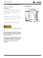


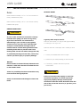
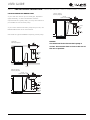

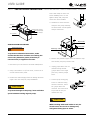

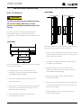

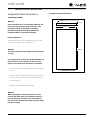
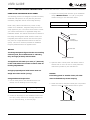
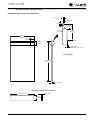


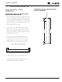


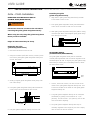
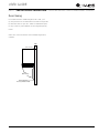
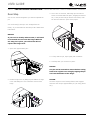

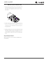
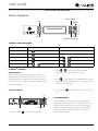
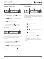
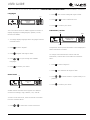
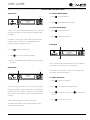
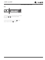
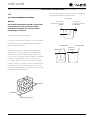

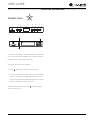
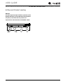


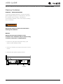


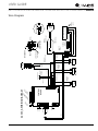

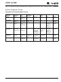


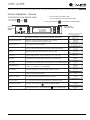
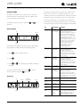


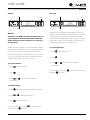
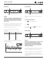


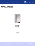


![Maximum Model service Manual.ppt [호환 모드]](http://vs1.manualzilla.com/store/data/006002079_1-f9e925e4876feffe85b493d91263fd66-150x150.png)