1
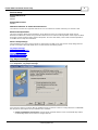
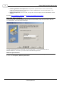
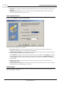
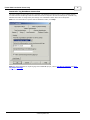
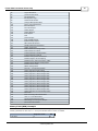
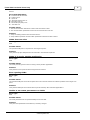
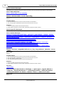
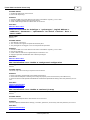
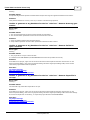
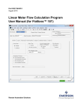
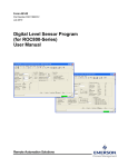
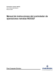
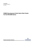
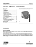
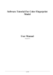
Fisher ROC Plus Serial
Driver Help
© 2011 Kepware Technologies
Fisher ROC Plus Serial Driver Help
2
Table of Contents
Table of Contents
2
Fisher ROC Plus Serial Driver Help
4
Overview
4
Device Setup
5
Tag Import Settings
5
More Tag Import Settings
6
Address Specification
6
Operator Identification
7
Time Synchronization
8
Modem Setup
8
Data Types Description
9
Automatic Tag Database Generation
11
Address Descriptions
12
Logical / Location Details
12
ROC Plus Point Types
12
Binary Field (BIN) Example
13
Error Descriptions
15
15
Address Validation
Address '<address>' is out of range for the specified device or register
15
Data Type '<type>' is not valid for device address '<address>'
16
Device address '<address>' contains a syntax error
16
Device address '<address>' is Read Only
16
Missing address
16
16
Serial Communications
Communications error on '<channel name>' [<error mask>]
16
COMn does not exist
17
COMn is in use by another application
17
Error opening COMn
17
Unable to set comm parameters on COMn
17
18
Device Status Messages
Device '<device name>' is not responding
18
18
Device Specific Messages
Device '<device>' responded with error. (Tag '<tag address>')-Details: '<error code>'
Failed to obtain data block for PointType = <point type>, Logical Address = <address>, Starting Parameter = <starting parameter>, Ending Parameter <ending parameter> for device '<device>'. Error = <ROC
error code>
18
18
Failed to write data for PointType = '<point type>', Logical Address = '<address>', Parameter = '<parameter>' for device '<device>'. Error = '<error code>'
19
ROC initialization error: Unable to read general configuration
19
ROC initialization error: Unable to retrieve I/O map
19
www. kepware.com
Fisher ROC Plus Serial Driver Help
3
The username or password supplied was not accepted. Error = 6
20
The username or password supplied was not accepted. Error = 63
20
Write request rejected on Read Only item reference '<channel name>' '<device name>' '<address>'
20
Automatic Tag Database Generation Error Messages
20
Error importing CSV tag record <record number>: Address '<Address>' is out of range for the specified
device or register
20
Unable to generate a tag database for device '<device>'. Reason: Auto tag generation
21
Unable to generate a tag database for device '<device>'. Reason: Failed to open recordset
21
Unable to generate a tag database for device '<device>'. Reason: Input file is corrupt
21
Unable to generate a tag database for device '<device>'. Reason: Input file not found
22
Unable to generate a tag database for device '<device>'. Reason: Low memory resources
22
22
ROC Plus Error Codes
Index
24
www. kepware.com
Fisher ROC Plus Serial Driver Help
4
Fisher ROC Plus Serial Driver Help
Help version 1.023
CONTENTS
Overview
What is the Fisher ROC Plus Serial Driver?
Device Setup
How do I configure a device for use with this driver?
Data Types Description
What data types does this driver support?
Automatic Tag Database Generation
How can tags be automatically created for this driver?
Address Descriptions
How do I address a data location on a Fisher ROC Plus Serial device?
Error Descriptions
What error messages does the Fisher ROC Plus Serial driver produce?
Overview
The Fisher ROC Plus Serial Driver provides an easy and reliable way to connect Fisher ROC Plus Serial controllers
to OPC Client applications, including HMI, SCADA, Historian, MES, ERP and countless custom applications. This
driver is intended for use with the following ROC Plus protocol devices: ROC809 and ROC827.
Note: For more information on the Opcodes available in the ROC Plus protocol, as well as point types and parameters, refer to the device's ROC Plus Protocol User Manual.
www. kepware.com
Fisher ROC Plus Serial Driver Help
5
Device Setup
Supported Devices
ROC809
ROC827
Supported Protocol
ROC Plus
Maximum Number of Channels and Devices
The maximum number of supported channels is 100. The maximum number of devices per channel is 255.
Ethernet Encapsulation
This driver supports Ethernet Encapsulation, which allows the driver to communicate with serial devices
attached to an Ethernet network using a Serial-to-Ethernet server. Ethernet Encapsulation mode may be enabled
through the Communications tab in Channel Properties. For more information, refer to "Ethernet Encapsulation"
in the OPC Server's help documentation.
Device Setup Dialogs
General dialogs in the device setup process are described in the OPC server help. Device setup dialogs that are
specific to the Fisher Plus ROC Serial driver are described in the following topics.
Tag Import Settings
More Tag Import Settings
Address Specification
Operator Identification
Time Synchronization
Tag Import Settings
To view or change the Tag Import settings after the device has been added, right-click on the device and then
select Properties | Tag Import Settings.
Users have the option to create an OPC tag database based on either the device's configuration file or a ROCLINK
800 project file. Descriptions of the parameters are as follows:
l
Create tag database from device: This parameter specifies that the driver will automatically create a
set of OPC tags based on the device's configuration file.
www. kepware.com
Fisher ROC Plus Serial Driver Help
6
l
Create tag database from import file: This parameter specifies that the driver will automatically
create a set of OPC tags based on a project file created in ROCLINK 800. Use the browse button (...) to
locate the file (*.800) to be imported.
l
Display Descriptions?: When checked, the tags will include descriptions from the ROCLINK 800 master
database.
See Also: More Tag Import Settings and Automatic Tag Database Generation.
More Tag Import Settings
To view or change the Tag Import Settings after the device has been added, right-click on the device and then
select Properties | More Tag Import Settings.
To create a tag database from an import file, use the browse button (...) to locate the ROC.mdb and
ROCLINK.MDW files. These files are provided with the ROCLINK 800 application.
Address Specification
To view or change the Address Specification settings after the device has been added, right-click on the device
and then select Properties | Address Specification.
www. kepware.com
Fisher ROC Plus Serial Driver Help
7
Enter the Host ROC Unit, Host ROC Group, Destination ROC Unit and Destination ROC Group values.
The valid range for these fields is 1 through 255.
Operator Identification
To view or change the Operator Identification settings after the device has been added, right-click on the device
and then select Properties | Operator Identification.
This dialog is used to specify the operator identification values User Name and Password, which will be used
when logging into the ROC Plus device during initialization. Descriptions of the parameters are as follows:
l
User Name: This parameter defines the User Name. Enter three characters (as set in the device). Three
characters are required.
www. kepware.com
Fisher ROC Plus Serial Driver Help
8
l
Password: This parameter defines the Operator Password. Enter four numeric characters between 0000
and 9999.
l
Enable Access Level: When checked, this parameter specifies that the ROC Plus device has defined
access levels. Enter the access level (0 to 5).
Time Synchronization
To view or change the Time Synchronization settings after the device has been added, right-click on the device
and then select Properties | Time Synchronization.
Descriptions of the parameters are as follows:
l
Local Time or UTC: This parameter specifies Local time (local to the PC on which the OPC server is
installed) or Universal time (UTC: Coordinated Universal Time).
l
Synchronization Method: This parameter specifies the method of synchronization: Disabled, Absolute
or Interval. Synchronization adjusts the ROC device clock.
When Disabled is selected, the driver will not perform time synchronization. When Absolute is selected,
the driver will perform time synchronization once daily at the time specified in Absolute Sync Time.
When Interval is selected, the driver will perform time synchronization every x minutes. The default setting is Disabled.
l
Absolute Sync Time: This parameter specifies the time at which the driver will perform time synchronization each day.
l
Synchronization Interval: This parameter specifies the synchronization interval in minutes. The driver
will perform time synchronization every x minutes.
Modem Setup
This driver supports modem functionality. For more information, please refer to the topic "Modem Support" in the
OPC Server Help documentation.
www. kepware.com
Fisher ROC Plus Serial Driver Help
9
Data Types Description
Data Types
Description
Boolean
Single bit
Char
Signed 8 bit value
bit 0 is the low bit
bit 6 is the high bit
bit 7 is the sign bit
Byte
Unsigned 8 bit value
bit 0 is the low bit
bit 7 is the high bit
Short
Signed 16 bit value
bit 0 is the low bit
bit 14 is the high bit
bit 15 is the sign
Word
Unsigned 16 bit value
bit 0 is the low bit
bit 15 is the high bit
Word
Point Type 100, parameters 3-5 are HOURMINUTE. This driver represents
HOURMINUTE this data type as Word.
Length: 2 Bytes. Time is listed as a decimal based number. The first two
digits represent the hour and the last two digits represent the minute.
Range: 9999, 0-23 for 2 MS Digits; 0-59 for 2 LS Digits
Special Meanings: 9999 = Disabled
Long
Signed 32 bit value
bit 0 is the low bit
bit 30 is the high bit
bit 31 is the sign
DWord
Unsigned 32 bit value
bit 0 is the low bit
bit 31 is the high
Float
32 bit floating point value
bit 0 is the low bit
bit 31 is the high bit
DWord
TLP
32 bit value: Point 'T'ype, 'L'ogical or Point Number, and 'P'arameter
Number.*
Uses three bytes. The top byte goes unused.
l
The type refers to the point type number.**
l
The location/logical number refers to individual points.
The parameter is a number assigned to each piece of data contained in a given point type.
557158: BIN = 00001000 10000000 01100110. 01100110 = Point Type
102, 10000000 = Location 128, 00001000 = Parameter 8.
l
DWord TLP
Example
The resulting TLP is 102-128.8
String
ASCII string padded with spaces.
Date
The number of seconds since Jan 1 1970 @ 00:00:00.
Date Example Date format:YYYY-MM-DDTHH:MM:SS.000.
2000-01-01T12:30:45.000
www. kepware.com
Fisher ROC Plus Serial Driver Help
10
*For more information, refer to Logical/Location Details.
**For more information, refer to ROC Plus Point Types.
www. kepware.com
Fisher ROC Plus Serial Driver Help
11
Automatic Tag Database Generation
This driver makes use of the OPC server's Automatic Tag Database Generation feature. When enabled, this feature will build a list of OPC tags within the OPC server that correspond to the device's data points. Automatic Tag
Database Generation is configured by the settings on the Database Creation tab in Device Properties.
Note: For more information on specific tabs in Database Creation, click Help.
Note: For more information on importing tags from a ROCLINK project, refer to Tag Import Settings and More
Tag Import Settings.
www. kepware.com
Fisher ROC Plus Serial Driver Help
12
Address Descriptions
Overview of ROC Addressing Format
ROC addresses are divided first by Point Type, then Logical Address and finally Parameter Index within the Point
Type. Some parameters are further broken out into individual bits. The general format is as follows:
T-L.P
where "T" is the Point Type, "L" is the Logical Address and "P" is the Parameter Index.
Parameters that are further broken out into individual bits are addressed as follows:
T-L.P:B
where B is the bit offset.
Note: For example, the address 1-50.3:2 indicates the following:
1
Point Type
50
Logical Address
3
Parameter
2
Bit Offset
Additional Explanations
The following topics provide a further explanation of ROC addressing. For a detailed listing of all point types'
access, data type, length and description, refer to the device's ROC Plus Protocol User Manual.
Logical / Location Details
ROC Plus Point Types
Binary Field (BIN) Example
Logical / Location Details
Within each point type, individual points are referenced by a Location or a Logical Number. The Location used by
ROC Plus Protocol for point types 101 to 109 is based on a physical input or output (I/O) module and point location. All other point types use a logical number and are simply numbered in sequence.
Note: The "L" in the TLP references scheme.
Physical Point Numbers 1 to 160
For point types 101 through 109, there are location numbers for the field I/O. For the diagnostic inputs, the
scheme is as follows:
l
Location Numbers 16 to 160 are assigned to field I/O. For example, if there was an I/O module in slot 1
with 4 points on it, they would be points 16 through 19.
l
Location Numbers 0 to 15 are assigned to the system I/O. For example, the five diagnostic points in a
ROC800-Series would be 0 through 4.
Logical Point Numbers 0 to 127
For all other point types (except 101-109), the logical number is 0 to x, where x is one less than the total number
of points that exist for that point type. For example, the 16 PIDs would be logical numbers 0 through 15.
Note: For a detailed listing of all point types' access, data type, length and description, refer to the device's ROC
Plus Protocol User Manual.
ROC Plus Point Types
For a detailed listing of all point types' parameters, access, data type, length and description, refer to the device's
ROC Plus Protocol User Manual.
Point Type
Description
85
HART
91
System Variables
www. kepware.com
Fisher ROC Plus Serial Driver Help
13
92
Logon Parameters
95
Communication Ports
96
FST Parameters
97
FST Register Tags
98
Soft Point Parameters
99
Configurable Opcode Table
100
Power Control Parameters
101
Discrete Inputs
102
Discrete Outputs
103
Analog Inputs
104
Analog Outputs
105
Pulse Inputs
106
RTD
107
Thermocouple
108
Multi-Variable Sensor
109
System Analog Inputs
110
PID Control Parameters
111
Sampler/Odorizer Parameters
112
Station Parameters
113
Orifice Meter Run Configuration
114
Orifice Meter Run Values
115
Turbine Meter Run Configuration
116
Turbine Meter Run Values
117
Modbus Configuration Parameters
118
Modbus Register to TLP Mapping
119
Modbus Event, Alarm and History Table
120
Modbus Master Modem Configuration
121
Modbus Master Table
122
DS800 Configuration
123
Security -- Group Configuration
124
History Segment Configuration
125
History Segment 0 Point Configuration
126
History Segment 1 Point Configuration
127
History Segment 2 Point Configuration
128
History Segment 3 Point Configuration
129
History Segment 4 Point Configuration
130
History Segment 5 Point Configuration
131
History Segment 6 Point Configuration
132
History Segment 7 Point Configuration
133
History Segment 8 Point Configuration
134
History Segment 9 Point Configuration
135
History Segment 10 Point Configuration
136
ROC Clock
137
Internet Configuration Parameters
138
User C++ Host Parameters
139
Smart I/O Module Information
140
Alternating Current Input / Output
141
Advanced Pulse Module
Binary Field (BIN) Example
The table below shows an example alarm code from an Analog Input Point Type. This is used to demonstrate how
a binary parameter is returned. A "1" in any bit indicates that it is active or enabled.
Low Alarm
Response Code
Bit
0
0
www. kepware.com
Fisher ROC Plus Serial Driver Help
14
Low Low Alarm
0
1
High Alarm
0
2
High High Alarm
0
3
Rate Alarm
0
4
Not Used
0
5
Point Fail Alarm
0
6
Scanning Disabled Alarm
1
7
www. kepware.com
Fisher ROC Plus Serial Driver Help
15
Error Descriptions
The following error/warning messages may be generated. Click on the link for a description of the message.
Address Validation
Address '<address>' is out of range for the specified device or register
Data Type '<type>' is not valid for device address '<address>'
Device address '<address>' contains a syntax error
Device address '<address>' is Read Only
Missing address
Serial Communications
Communications error on '<channel name>' [<error mask>]
COMn does not exist
COMn is in use by another application
Error opening COMn
Unable to set comm parameters on COMn
Device Status Messages
Device '<device name>' is not responding
Device Specific Messages
Device '<device>' responded with error. (Tag '<tag address>')-Details: '<error code>'
Failed to obtain data block for PointType = <point type>, Logical Address = <address>, Starting
Parameter = <starting parameter>, Ending Parameter <ending parameter> for device '<device>'.
Error = <ROC error code>
Failed to write data for PointType = '<point type>', Logical Address = '<address>', Parameter =
'<parameter>' for device '<device>'. Error = '<error code>'
ROC initialization error: Unable to read general configuration
ROC initialization error: Unable to retrieve I/O map
The username or password supplied was not accepted. Error = 6
The username or password supplied was not accepted. Error = 63
Write request rejected on Read Only item reference '<channel name>' '<device name>'
'<address>'
Automatic Tag Database Generation Error Messages
Error importing CSV tag record <record number>: Address '<Address>' is out of range for the specified device or register
Unable to generate a tag database for device '<device>'. Reason: Auto tag generation
Unable to generate a tag database for device '<device>'. Reason: Failed to open recordset
Unable to generate a tag database for device '<device>'. Reason: Input file is corrupt
Unable to generate a tag database for device '<device>'. Reason: Input file not found
Unable to generate a tag database for device '<device>'. Reason: Low memory resources
See Also: ROC Plus Error Codes
Address Validation
The following error/warning messages may be generated. Click on the link for a description of the message.
Address Validation
Address '<address>' is out of range for the specified device or register
Data Type '<type>' is not valid for device address '<address>'
Device address '<address>' contains a syntax error
Device address '<address>' is Read Only
Missing address
Address '<address>' is out of range for the specified device or register
Error Type:
Warning
Possible Cause:
www. kepware.com
Fisher ROC Plus Serial Driver Help
16
A tag address that has been specified statically references a location that is beyond the range of supported locations for the device.
Solution:
Verify that the address is correct; if it is not, re-enter it in the client application.
Data Type '<type>' is not valid for device address '<address>'
Error Type:
Warning
Possible Cause:
A tag address that has been specified statically has been assigned an invalid data type.
Solution:
Modify the requested data type in the client application.
Device address '<address>' contains a syntax error
Error Type:
Warning
Possible Cause:
A tag address that has been specified statically contains one or more invalid characters.
Solution:
Re-enter the address in the client application.
Device address '<address>' is Read Only
Error Type:
Warning
Possible Cause:
A tag address that has been specified statically has a requested access mode that is not compatible with what the
device supports for that address.
Solution:
Change the access mode in the server application.
Missing address
Error Type:
Warning
Possible Cause:
A tag address that has been specified statically has no length.
Solution:
Re-enter the address in the server application.
Serial Communications
The following error/warning messages may be generated. Click on the link for a description of the message.
Serial Communications
Communications error on '<channel name>' [<error mask>]
COMn does not exist
COMn is in use by another application
Error opening COMn
Unable to set comm parameters on COMn
Communications error on '<channel name>' [<error mask>]
Error Type:
www. kepware.com
Fisher ROC Plus Serial Driver Help
17
Serious
Error Mask Definitions:
B = Hardware break detected.
F = Framing error.
E = I/O error.
O = Character buffer overrun.
R = RX buffer overrun.
P = Received byte parity error.
T = TX buffer full.
Possible Cause:
1. The serial connection between the device and the Host PC is bad.
2. The communication parameters for the serial connection are incorrect.
Solution:
1. Verify the cabling between the PC and the device.
2. Verify that the specified communication parameters match those of the device.
COMn does not exist
Error Type:
Fatal
Possible Cause:
The specified COM port is not present on the target computer.
Solution:
Verify that the proper COM port has been selected in the Channel Properties.
COMn is in use by another application
Error Type:
Fatal
Possible Cause:
The serial port assigned to a device is being used by another application.
Solution:
Verify that the correct port has been assigned to the channel.
Error opening COMn
Error Type:
Fatal
Possible Cause:
The specified COM port could not be opened due to an internal hardware or software problem on the target computer.
Solution:
Verify that the COM port is functional and may be accessed by other Windows applications.
Unable to set comm parameters on COMn
Error Type:
Fatal
Possible Cause:
The serial parameters for the specified COM port are not valid.
Solution:
Verify the serial parameters and make any necessary changes.
www. kepware.com
Fisher ROC Plus Serial Driver Help
18
Device Status Messages
The following error/warning messages may be generated. Click on the link for a description of the message.
Device Status Messages
Device '<device name>' is not responding
Device '<device name>' is not responding
Error Type:
Serious
Possible Cause:
1. The connection between the device and the Host PC is intermittent.
2. The communication parameters for the serial connection are incorrect.
Solution:
1. Verify the cabling between the PC and the device.
2. Verify that the specified communication parameters match those of the device.
Device Specific Messages
The following error/warning messages may be generated. Click on the link for a description of the message.
Device Specific Messages
Failed to obtain data block for PointType = <point type>, Logical Address = <address>, Starting
Parameter = <starting parameter>, Ending Parameter <ending parameter> for device '<device>'.
Error = <ROC error code>
Failed to write data for PointType = '<point type>', Logical Address = '<address>', Parameter =
'<parameter>' for device '<device>'. Error = '<error code>'
ROC initialization error: Unable to read general configuration
ROC initialization error: Unable to retrieve I/O map
Device '<device>' responded with error. (Tag '<tag address>')-Details: '<error code>'
The username or password supplied was not accepted. Error = 6
The username or password supplied was not accepted. Error = 63
Write request rejected on Read Only item reference '<channel name>' '<device name>'
'<address>'
Device '<device>' responded with error. (Tag '<tag address>')-Details: '<error
code>'
Error Type:
Serious
Possible Cause:
1. The connection between the device and the Host PC is intermittent.
2. The communication parameters for the serial connection are incorrect.
3. The value written is out of range.
4. The write was performed while in an incorrect setup area.
Solution:
1. Check the cabling between the PC and the device.
2. Verify that the specified communication parameters match those of the device.
See Also:
Device Setup
Failed to obtain data block for PointType = <point type>, Logical Address =
<address>, Starting Parameter = <starting parameter>, Ending Parameter
<ending parameter> for device '<device>'. Error = <ROC error code>
Error Type:
Serious
www. kepware.com
Fisher ROC Plus Serial Driver Help
19
Possible Cause:
1. Invalid tag address for point in block.
2. Device not responding.
Solution:
1. Consult the ROC error code reference for further information regarding <error code>.
2. Verify the cabling between the PC and the device.
3. Confirm that all tags within this block exist on the device.
See Also:
ROC Plus Error Codes
Failed to write data for PointType = '<point type>', Logical Address =
'<address>', Parameter = '<parameter>' for device '<device>'. Error =
'<error code>'
Error Type:
Serious
Possible Cause:
1. The address is incorrect.
2. The unit does not support the particular address point.
3. The privileges for the logged-in user do not permit this operation.
Solution:
1. Consult the ROC error code reference for further information regarding <error code>.
2. Correct the address.
3. Confirm that the address is supported by the controller in use.
4. Supply an operator identification with sufficient privileges.
See Also:
ROC Plus Error Codes
ROC initialization error: Unable to read general configuration
Error Type:
Serious
Possible Cause:
The driver may not be receiving a response from the device.
Solution:
1. Ensure the device is physically connected and powered on.
2. Check that the COM port is working and configured properly at the channel level (in the OPC server).
3. Check the device-level Operator Identification and Address Specification settings and verify that they are correct.
See Also:
Operator Identification
Address Specification
ROC initialization error: Unable to retrieve I/O map
Error Type:
Serious
Possible Cause:
Access to the I/O Map has been restricted for the current user.
Solution:
Check the Operator Identification settings (username, password, access level) and verify that they are correct.
See Also:
Operator Identification
www. kepware.com
Fisher ROC Plus Serial Driver Help
20
The username or password supplied was not accepted. Error = 6
Error Type:
Serious
Possible Cause:
An access level has been enabled on the device but not in the driver.
Solution:
Check the Operator Identification settings and make sure the Enable Access Level checkbox is checked.
See Also:
Operator Identification
The username or password supplied was not accepted. Error = 63
Error Type:
Serious
Possible Cause:
The access level that has been enabled on the device is lower than the operator's access level.
Solution:
Check the Operator Identification settings and make sure the operator's access level is less than or equal to the
access level enabled in the device.
See Also:
Operator Identification
Write request rejected on Read Only item reference '<channel name>'
'<device name>' '<address>'
Error Type:
Warning
Possible Cause:
The driver was attempting to write to a Read Only datum in the ROC controller.
Solution:
1. Do not attempt to write to Read Only points.
2. In some situations, the Automatic Tag Generation process will identify Read Only datum as Read/Write, based
on the configuration that the driver retrieved from the ROC controller and the ROC specification. Nonetheless, the
ROC controller itself is the final authority on whether a datum is writable.
Note:
For more information, refer to the controller's documentation.
Automatic Tag Database Generation Error Messages
The following error/warning messages may be generated. Click on the link for a description of the message.
Automatic Tag Database Generation Error Messages
Error importing CSV tag record <record number>: Address '<Address>' is out of range for the specified device or register
Unable to generate a tag database for device '<device>'. Reason: Auto tag generation
Unable to generate a tag database for device '<device>'. Reason: Failed to open recordset
Unable to generate a tag database for device '<device>'. Reason: Input file is corrupt
Unable to generate a tag database for device '<device>'. Reason: Input file not found
Unable to generate a tag database for device '<device>'. Reason: Low memory resources
Error importing CSV tag record <record number>: Address '<Address>' is out
of range for the specified device or register
Error Type:
www. kepware.com
Fisher ROC Plus Serial Driver Help
21
Warning
Possible Cause:
An imported tag address specifies a location that is beyond the range of supported locations for the device.
Solution:
Verify that the address is correct; if it is not, re-enter it in the file being imported.
Unable to generate a tag database for device '<device>'. Reason: Auto tag generation
Error Type:
Serious
Possible Cause:
1. The connection between the device and the Host PC is intermittent.
2. The communication parameters for the serial connection are incorrect.
Solution:
1. Verify the cabling between the PC and the device.
2. Verify that the specified communication parameters match those of the device.
Unable to generate a tag database for device '<device>'. Reason: Failed to
open recordset
Error Type:
Warning
Possible Cause:
1. The project file is corrupt or does not exist.
2. Locations for the ROC.MDB and/or ROCLINK.MDW files have been specified incorrectly.
Solution:
In the OPC server project, right-click on the device and then select Properties from the context menu. In the
Device Properties dialog, click on the Tag Import Settings and More Tag Import Settings tabs, and check the
name of the project file that will be imported.
See Also:
Tag Import Settings
More Tag Import Settings
Automatic Tag Database Generation
Unable to generate a tag database for device '<device>'. Reason: Input file is
corrupt
Error Type:
Warning
Possible Cause:
The Automatic Tag Generation import file is corrupt.
Solution:
In the OPC server project, right-click on the device and then select Properties from the context menu. In the
Device Properties dialog, click on the Tag Import Settings and More Tag Import Settings tabs. Review the settings
and check the import file. If necessary, re-export the project file from within ROCLINK800.
See Also:
Tag Import Settings
More Tag Import Settings
Automatic Tag Database Generation
www. kepware.com
Fisher ROC Plus Serial Driver Help
22
Unable to generate a tag database for device '<device>'. Reason: Input file not
found
Error Type:
Warning
Possible Cause:
The Automatic Tag Generation import file cannot be found.
Solution:
In the OPC server project, right-click on the device and then select Properties from the context menu. In the
Device Properties dialog, click on the Tag Import Settings and More Tag Import Settings tabs, and check the
name of the project file that will be imported.
See Also:
Tag Import Settings
More Tag Import Settings
Automatic Tag Database Generation
Unable to generate a tag database for device '<device>'. Reason: Low memory
resources
Error Type:
Warning
Possible Cause:
The memory required for Automatic Tag Generation could not be allocated. The process is aborted.
Solution:
Close any unused applications and/or increase the amount of virtual memory. Then, try again.
ROC Plus Error Codes
Note regarding Opcode 255: Opcode 255 is an error message indicator that returns an error code.
Error Code
Description
1
Invalid Opcode request.
2
Invalid parameter number.
3
Invalid logical number.
4
Invalid point type.
5
Received too many data bytes.
6
Received too few data bytes.
12
Obsolete (reserved, but not used).
13
Outside valid address range.
14
Invalid history request.
16
Invalid event entry.
17
Requested too many alarms.
18
Requested too many events.
19
Write to Read Only parameter. Exception for Opcode 166, which can have
multiple parameters. Some of these may be Read Only and some may not.
20
Security error.
21
Invalid security logon.
22
Invalid store and forward path.
24
History configuration in progress.
25
Invalid parameter range.
29
Invalid 1 day history index request.
30
Invalid history point.
31
Invalid Min/Max request.
32
Invalid TLP.
33
Invalid time.
www. kepware.com
Fisher ROC Plus Serial Driver Help
23
34
Illegal Modbus range.
63
Requested access level too high.
65535
Device not responding.
www. kepware.com
Fisher ROC Plus Serial Driver Help
24
Index
A
Access Level
8
Address '<address>' is out of range for the specified device or register
15
Address Descriptions
12
Address Specification
6
Address Validation
15
Automatic Tag Database Generation
11
Automatic Tag Database Generation Error Messages
20
B
BIN
13
Binary Field Example
13
C
Communications error on '<channel name>' [<error mask>]
16
COMn does not exist
17
COMn is in use by another application
17
D
Data Type '<type>' is not valid for device address '<address>'
Data Types Description
16
9
Device '<device name>' is not responding
18
Device '<device>' responded with error. (Tag '<tag address>') - Details: '<error code>'
18
Device address '<address>' contains a syntax error
16
Device address '<address>' is Read Only
16
Device Setup
5
Device Specific Messages
18
Device Status Messages
18
E
Error Descriptions
15
Error importing CSV tag record <record number>: Address '<Address>' is out of range for 20
the specified device or register
Error opening COMn
17
F
Failed to obtain data block for PointType = <point type>, Logical Address = <address>,
Starting Parameter = <starting parameter>, Ending Parameter <ending parameter> for
device '<device>'. Error = <ROC error code>
18
Failed to write data for PointType = '<point type>', Logical Address = '<address>', Param- 19
www. kepware.com
Fisher ROC Plus Serial Driver Help
25
eter = '<parameter>' for device '<device>'. Error = '<error code>'
H
Help Contents
4
L
Location Details
12
Logical
12
M
Missing address
16
Modem Setup
8
More Tag Import Settings
6
O
Operator Identification
7
Overview
4
R
ROC initialization error: Unable to read general configuration
19
ROC initialization error: Unable to retrieve I/O map
19
ROC Plus Error Codes
22
ROC Plus Point Types
12
S
Serial Communications
16
T
Tag Import Settings
5
The username or password supplied was not accepted. Error = 6
20
The username or password supplied was not accepted. Error = 63
20
Time Synchronization
8
U
Unable to generate a tag database for device '<device>'. Reason: Auto tag generation
21
Unable to generate a tag database for device '<device>'. Reason: Failed to open recordset
21
Unable to generate a tag database for device '<device>'. Reason: Input file is corrupt
21
Unable to generate a tag database for device '<device>'. Reason: Input file not found
22
Unable to generate a tag database for device '<device>'. Reason: Low memory resources
22
Unable to set comm parameters on COMn
17
W
Write request rejected on Read Only item reference '<channel name>' '<device name>'
www. kepware.com
20