1
FASTCAM SA7
The copyright of this manual is held by Photron LIMITED.
Product specifications and manual contents can change without advanced notification.
This manual was created taking every possible measure to ensure the accuracy of its contents. However, if you find a section which is unclear, a mistake, or an
omission, please contact Photron LIMITED using the contact information provided at the end of the manual.
Photron LIMITED bears no responsibility for the results of using the product or from following the instructions in this manual.
Introduction
Thank you for your purchase of Photron’s high-speed camera system, the “FASTCAM SA7” (referred to
below as the system). This manual contains the operating instructions and warnings necessary for using
the system.
Before using the system, please read the entire manual. If any part of this manual is unclear, contact
Photron using the contact information printed at the back of the manual.
After you finish reading the manual, store it in a safe place along with the warranty card and refer back to it
when necessary.
Manual Notation
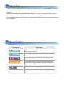
The following icons and symbols are used in the explanations in this manual.
Icon/Symbol
Description
This symbol indicates supplementary items to be aware of
when using the software.
This symbol indicates the location of a reference.
This symbol indicates content that should always be read.
This symbol indicates instructions that should always be
followed when using the software, or things to be careful of
when using the system.
This symbol indicates a space for you to make notes.
"
"
This symbol is used to indicate the names of items on a
screen, references, dialog names, and connectors.
Using the Manual
This section explains the layout of the manual.
Introduction
The introduction explains the manual and safety precautions.
Chapter. 1 Overview
This chapter gives an overview of the system and an explanation of its features.
Chapter. 2 Setup
This chapter gives an overview of the components that make up the system. It also explains basic keypad
operation and a list of items that should be checked before using the system.
Chapter. 3 Recording
This chapter explains operations related to recording.
Chapter. 4 Connecting a PC
This chapter explains the procedure for connecting the system to a PC. Refer to the “Photron FASTCAM
Viewer User’s Manual” for additional details on using a PC to control the system.
Chapter. 5 Product Specifications
This chapter explains the system’s specifications.
Chapter. 6 Warranty
This chapter explains about the warranty.
Chapter. 7 Contacting Photron
This chapter lists the contact information to use when contacting Photron if the system malfunctions or if
a portion of the manual is unclear.
Using the System Safely and Correctly
In order to prevent injury to yourself and others, and to prevent damage to property, carefully observe the
following safety precautions.
Photron has given its full attention to the safety of this system. However, the extent of damage and injury
potentially caused by ignoring the content of the safety precautions and using the system incorrectly is
explained next. Please pay careful attention to the content of the safety precautions when using the
system.
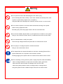
Warning
Caution
This symbol indicates actions that carry the risk that a person could receive a
serious injury.
This symbol indicates actions that carry the risk that a person could receive a
moderate injury, or that damage to physical property might occur.
The safety precautions to be observed are explained with the following symbols.
This symbol indicates actions that require caution.
This symbol indicates actions that are prohibited and must be avoided.
This symbol indicates actions that must always be performed.
Warning
■ Do not perform actions that will damage the AC cable or plug.
(Do not damage the cable, modify it, use it near a heater, excessively bend, twist
or pull on it, place heavy objects on it, or bundle it.)
Using the cable when damaged can cause fire, electric shock, or a short circuit.
■ Do not use the system in a manner which will exceed the rating of the power
outlet or wiring equipment used.
Exceeding the power rating might cause a fire from excessive heat.
■ Do not insert metallic objects inside, or pour liquids such as water on, the system.
Doing so can cause fire, electric shock, or malfunction from short circuit or heat.
■ Do not disassemble or modify the system.
There are high voltages inside the system that can cause electric shock.
■ Do not plug in or unplug the power cord with wet hands.
Doing so can cause electric shock.
■ This chapter lists the contact information to use when contacting Photron if the
system malfunctions or if a portion of the manual is unclear.
Not fully plugging in the power cable can cause fire from electric shock or heat.
■ When something is wrong with the system, unplug the power cable immediately.
- When a foreign substance or liquid, such as metal or water, gets inside.
- When the outer case is broken or damaged, such as from a fall.
- When the system produces smoke, a strange smell, or strange sound.
Using the system in these conditions might cause a fire or electric shock.
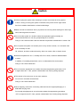
Caution
■ Always unplug the system when cleaning it or when it is unused for a long period
of time. Leaving or storing the system connected to the power source might cause
fire from insulation deterioration or electrical discharge.
■Please consult us in advance when you perform an event by which laser light or direct rays
fall on the image sensor surface.
■ Do not set the system in a location where the temperature gets unusually hot.
The trunk and inside of a car can get especially hot in summer.
Doing so can cause the outer case and internal components to deteriorate or cause a fire.
■ Do not place the system in a location prone to oily smoke or steam, or in a location with
a lot of humidity or dust.
Oil, moisture, and dust conduct electricity, which can cause a fire or electric shock.
■ Ambient temperature 0-40° C, humidity 85% RH or lower, maximum altitude 2000m
or lower.
In addition, if exceeding these limits, use in a condensation-free environment.
Doing so can cause malfunction.
■ Do not store the equipment in a location where the temperature goes below -20°C
or higher than 60°C. Also, prevent condensation from forming during shipment
■ This device is for indoor use, do not use it outdoors.
Do not use in a location that has dust.
Doing so can cause malfunction.
■ When shipping, remove the connecting cable and use the original packaging or a
dedicated carrying case.
Do not ship the equipment in an environment where the temperature goes below
-20°C or higher than 60°C. Also, prevent condensation from forming during shipment
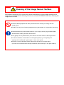
Cleaning of the Image Sensor Surface
Electrostatic Discharge (ESD) events may cause immediate and unrecoverable damage to the
image sensor. Please read the following instructions and take EXTREME CARE when cleaning the
image sensor surface.
■ ALWAYS take appropriate anti-static precautions when cleaning or working near the
Image sensor.
■ DO NOT use any form of cleaning equipment using electrostatic or ‘charged fiber’ technology.
■ Please discharge any electrostatic build up in your body by touching a grounded metallic
Surface before working near the camera sensor.
■ Very gently, use only clean and dry air to remove dust from surface of the image sensor.
■ To remove stubborn contamination use the highest grade (e.g. VLSI grade) pure
Isopropyl alcohol (IPA) with optical wipes of ‘clean room’ grade.
■ Extreme care must be taken! Gently wipe across the sensor in a single action.
(DO NOT rub to avoid abrasive damage to delicate optical coatings on the glass surface.)
Table of Contents
Chapter. 1
1.1.
Overview
1
Product Overview and Features .............................................................................. 2
Chapter. 2
Setup
3
2.1.
System Components and Accessories .................................................................... 4
2.1.1.
Components ................................................................................................ 4
2.1.2.
Accessories/Options ................................................................................... 4
2.1.3.
Type ............................................................................................................ 5
2.2. Part Names .............................................................................................................. 6
2.2.1.
Camera Body .............................................................................................. 6
2.2.2.
Camera Body Part Names .......................................................................... 7
2.2.3.
Status Display LEDs on the Rear of the Camera Body .............................. 8
2.2.4.
Interchangeable Lens Mounts................................................................... 10
2.2.5.
I/O Port Connector .................................................................................... 11
2.2.6.
Power Supply Connector .......................................................................... 13
2.3. Device Connections ............................................................................................... 14
2.3.1.
Connecting the Power Supply................................................................... 14
2.3.2.
Connecting a PC ....................................................................................... 15
2.3.3.
Factory Default Setting ............................................................................. 15
Chapter. 3
3.1.
3.2.
3.3.
3.4.
Recording
17
Selecting the Frame Rate ...................................................................................... 18
Selecting the Resolution ........................................................................................ 18
Selecting the Shutter Speed .................................................................................. 19
Selecting the Trigger Mode .................................................................................... 19
3.4.1.
START Mode ............................................................................................. 19
3.4.2.
CENTER Mode ......................................................................................... 20
3.4.3.
END Mode................................................................................................. 20
3.4.4.
MANUAL Mode ......................................................................................... 20
3.5. LOW LIGHT Mode ................................................................................................. 21
3.6. White Balance Adjustment (Color Types Only) ...................................................... 21
3.6.1.
Using Preset White Balance (Color Types Only) ...................................... 21
3.6.2.
Using User White Balance (Color Types Only) ......................................... 21
3.7. Color Enhancement Function (Color Types Only) ................................................. 22
3.8. LUT (Look-Up Table) Operations ........................................................................... 22
3.8.1.
Using Preset LUT Patterns ....................................................................... 22
3.8.2.
Using a Custom LUT ................................................................................. 25
3.9. Edge Enhancement Function ................................................................................ 25
3.10. Input / Output Signal Types.................................................................................... 26
3.10.1. TRIG TTL IN Connector ............................................................................ 26
3.10.2. TRIG TTL OUT Connector ........................................................................ 26
3.10.3. TRIG SW IN Connector ............................................................................ 26
3.10.4. SYNC IN Connector .................................................................................. 26
3.10.5. GENERAL IN Connector ........................................................................... 27
3.10.6. GENERAL OUT (1, 2) Connector ............................................................. 27
3.11. Using External Triggers.......................................................................................... 28
3.11.1. Inputting an External Trigger Signal .......................................................... 28
3.11.2. Outputting External Trigger Signals .......................................................... 30
3.12. Using External Synchronization Signals ................................................................ 31
3.12.1. Inputting an External Synchronization Signal ........................................... 31
3.12.2. Outputting an External Synchronization Signal ........................................ 31
3.12.3. Synchronizing Multiple FASTCAM SA7 Systems(Multiple Unit
Synchronized Recording) .................................................................................................. 32
3.12.4. Synchronizing the System with Other Cameras (Mixed Device
Synchronized Recording) .................................................................................................. 34
3.13. GENERAL Signal Settings ..................................................................................... 35
3.13.1. GENERAL IN Signal Settings ................................................................... 35
3.13.2. GENERAL OUT Signal Settings ............................................................... 36
3.14. Signal Delay ........................................................................................................... 37
3.15. Using USER SW (Programmable Switch) ............................................................. 38
Chapter. 4
4.1.
Connecting a PC
39
Connecting the Gigabit Ethernet Interface to a PC ............................................... 40
4.1.1.
Connecting the System and a PC ............................................................. 41
4.1.2.
Setting the IP Address .............................................................................. 41
4.1.3.
Connecting Multiple Systems and a PC ................................................... 42
4.1.4.
Gigabit Ethernet Interface Initialization ..................................................... 42
4.1.5.
Camera IP Address Initialization ............................................................... 42
Chapter. 5
Product Specifications
43
5.1.
Specifications ......................................................................................................... 44
5.1.1.
Product Specifications............................................................................... 44
5.1.2.
General Specifications .............................................................................. 45
5.1.3.
AC / DC Adaptor ....................................................................................... 45
5.1.4.
Options ...................................................................................................... 46
5.1.5.
Frame Rate and Resolution ...................................................................... 48
5.1.6.
Recordable Image Count/Resolution ........................................................ 50
5.1.7.
Shutter Speed List..................................................................................... 51
5.2. Dimensions ............................................................................................................ 52
5.2.1.
Camera Body ............................................................................................ 52
5.2.2.
AC / DC Adaptor ....................................................................................... 53
Chapter. 6
6.1.
55
About the Warranty ................................................................................................ 56
Chapter. 7
7.1.
Warranty
Contacting Photron
57
Contact Information................................................................................................ 58
Chapter. 1 Overview
1.1. Product Overview and Features
1
FASTCAM SA7 Hardware Manual
Chapter. 1 Overview
1.1.
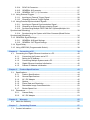
Product Overview and Features
The FASTCAM SA7 is a powerful engineering tool for use in research and development, design,
production, and quality control, and in numerous fields such as science, medicine, biology, aviation
and space. -The system features superior basic performance with megapixel resolution, an
ultra-sensitive image sensor capable of clear recording in low-light, and an high speed frame rate of
a maximum with full frame of 3,500fps (15K type: 2,000fps) It also allows operation from the PC
software via a gigabit Ethernet connection to more easily implement analysis of dynamic bodies that
had been difficult to analyze until now.
Use the state-of-the-art technology in the FASTCAM SA7 to slow down and observe high-speed
dynamic bodies and also as an input component for a dynamic image measurement system.
2
Chapter. 2 Setup
2.1. System Components and Accessories
2.2. Part Names
2.3. Device Connections
3
FASTCAM SA7 Hardware Manual
Chapter. 2 Setup
2.1.
System Components and Accessories
2.1.1.
Components
The system’s standard components are listed below. Remove the components from the packaging
and check them.
1.
Camera Body
One
2.
AC / DC Adaptor , AC Cable
One
3.
G type F Mount Adapter (body integrated)
One
4.
C Mount Adapter (cap integrated)
One
5.
Hexagonal Wrench for Changing Lens Mounts
(1.5 mm, 2 mm, 3 mm, 4 mm)
One each
6.
I/O Cable
One
7.
FASTCAM Series Setup Disk (Driver / Application CD)
One
8.
FASTCAM SA7 Hardware Manual (This Manual)
One
9.
Photron FASTCAM Viewer User's Manual
One
10. Making a Gigabit Ethernet Connection (Simple Procedure Manual)
One
11. Gigabit Ethernet Interface Cable (LAN Cable)
One
2.1.2.
Accessories/Options
The following options are available for the system.
1.
4 Output Trigger Box
2.
Spare Power Supply Connector (For Creating a Custom Cable)
3.
Dust-Proof Cover for the LAN Connector
4.
Carrying Case
5.
Memory Backup Battery
4
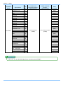
2.1.3.
Type
The system is split into types according to frame rate, color/monochrome, and amount of memory.
There are a total of 8 types according to the combination of options.
The types are listed below.
Max. Frame Rate
Full Frame
Max Frame Rate
Sensor Type
Color
30,000fps
3,500fps
Monochrome
Color
15,000fps
2,000fps
Monochrome
5
Memory
Type Name
4GB
FASTCAM SA7 type 30K-C1
8GB
FASTCAM SA7 type 30K-C2
4GB
FASTCAM SA7 type 30K-M1
8GB
FASTCAM SA7 type 30K-M2
4GB
FASTCAM SA7 type 15K-C1
8GB
FASTCAM SA7 type 15K-C2
4GB
FASTCAM SA7 type 15K-M1
8GB
FASTCAM SA7 type 15K-M2
FASTCAM SA7 Hardware Manual
Chapter. 2 Setup
2.2.
Part Names
The system is composed of components including the camera body, AC / DC Adaptor, and the
"Photron FASTCAM Viewer" control software (referred to below as PFV).
For each of the system components.
- Do not expose to shock outside of specifications.
- Do not use in an area with flammable gas or dust present.
- Do not place in an unstable location such as on an unstable platform or an incline.
- Do not disassemble or modify.
- Do not expose to liquids such as water.
- Do not use in a manner where excessive force is applied.
2.2.1.
Camera Body
The camera body contains IC memory for saving images and has been designed with the capability
to save high-speed images as uncompressed digital data. The camera body has a Gigabit Ethernet
interface to connect a PC to fully control the camera or download data, and interfaces for various I/O
(input/output) connectors for external synchronization/trigger signals.
Appearance
Rear
6
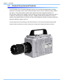
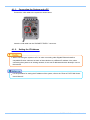
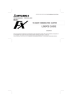
2.2.2.
Camera Body Part Names
Handle
FAN
Front
F Mount Plate
Status Display LEDs
POWER
Power Supply Switch
Backup Battely LEDs
USER
Programmable Switch
Reserved Connector
GIGABIT EHTER
Gigabit Ethernet
LAN Cable Connector
DC22-32V 65VA
Power Supply Connector
I/O PORT
I/O Port Connector
Rear
7
Reserved Connector
FASTCAM SA7 Hardware Manual
Chapter. 2 Setup
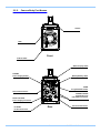
2.2.3.
Status Display LEDs on the Rear of the Camera Body
There are a number of LEDs on the rear of the system's camera body. These LEDs indicate the
status of the system. The meaning of each LED is explained here.
Status Display LEDs
POWER (Green)
LED ON: Power On
LED OFF: Power Off
IF LINK/TRANS (Red)
LED ON: The Gigabit Ethernet interface is connected
LED FLASHING: Data is transferring
LED OFF: The Gigabit Ethernet interface is not connected
TRIGGER (Yellow)
LED ON: A trigger signal has been input (illuminates for 0.1 s when the trigger signal is input)
LED OFF: A trigger signal has not been input
IRIG (Green)
This function is not available on this camera.
SYNC MODE (Red)
LED ON: In external synchronization mode
LED OFF: In internal synchronization mode
SYNC IN (Yellow)
LED ON: A synchronization signal is being input
LED OFF: A synchronization signal is not being input
REC READY (Yellow)
LED ON: Ready to record
LED FLASHING: ENDLESS recording ("REC" LED also simultaneously flashes)
LED OFF: Not ready to record
REC (Red)
LED FLASHING: Recording
LED OFF: Not ready to record
8
Statement of LED blinking status.
Working under LOW LIGHT mode.
LEDs except POWER (Green) and IF LINK/TRANS (Red) blink synchronously in a certain interval.
Initialization of Gigabit Ethernet Interface and Initialization of IP address.
LEDs except POWER (Green) and IF LINK/TRANS (Red) blink from left to right for 3 circles and right
to left for 3 circles alternately.
For Initialize Gigabit Ethernet Interface, refer to “4.1.4. Gigabit Ethernet Interface Initialization
Gigabit Ethernet", page 42.
Battery LED (Option)
CHARGE (Red)
LED ON:Battery in charging.
LED OFF:Not in charging.
FULL (Green) → (Yellow) → EMPTY (Red)
Indicator of residual battery capacity.
Green: residual battery capacity 100%~90%
Yellow: residual battery capacity 89%~21%
Red: residual battery capacity 20%~1%
Moreover, the status of battery is indicated by blinking of LED.
LED ON:Working under an External Power Supply state.
LED FLASHING:Battery Powered Memory Protect state.
9
FASTCAM SA7 Hardware Manual
Chapter. 2 Setup
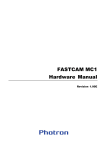
2.2.4.
Interchangeable Lens Mounts
The lens mount on the system can be changed according to the recording application.
There are three types of interchangeable lens mounts, "Nikon G type F Mount", "C Mount",
and Lens mount with filter changer.
How to change lens mounts (Nikon G type F Mount → C Mount)
1.
Remove the four M5 hexagonal socket bolts with the hexagonal wrench.
2.
Remove the Nikon G type F mount portion as a whole unit.
3.
Attach the C mount unit with the hexagonal socket bolts 90 degrees diagonally.
4.
After attaching the unit, always check to make sure it is not loose and rattles.
C Mount
G type F Mount
(Standard)
10
2.2.5.
I/O Port Connector
By inputting an external trigger or synchronization signal and by outputting exposure timing or
synchronization signal, these signals can be used as a part of the system. The input/output signal
connectors on the system have been bundled into a single connector, the "I/O port" connector, and it
is possible to connect to and access each type of signal by using the specialized multi-connector.
Do not input a signal other than the specified signal to the various connectors.
Use extreme caution as there is a risk of damage to both devices, the input device and the
output device.
I/O PORT (Camera Body)
ECJ.2B.326.CLD(LEMO)
For the signal which can be inputted, refer to “3.10. Input / Output Signal Types”, page 26.
11
FASTCAM SA7 Hardware Manual
Chapter. 2 Setup
Connector
Name
I/O PORT
Signal Name
Pin
No.
Camera body
Connector type No.
(Manufacturer)
Cable connector
type No.
(Manufacturer)
Input
connector
GENERAL OUT2
1
BNC
RESERVE
2
-
GND
3
BNC
RESERVE
4
-
RESERVE
5
-
RESERVE
6
-
RESERVE
7
-
RESERVE
8
-
RESERVE
9
-
RESERVE
10
-
SYNC IN
11
BNC
TRIGGER TTL IN
12
BNC
TRIGGER TTL OUT
13
ECJ.2B.326.CLD
FGJ.2B.326.CLLD92Z
BNC
GENERAL OUT1
14
(LEMO)
(LEMO)
BNC
GND
15
BNC
GND
16
BNC
RESERVE
17
-
RESERVE
18
-
GND
19
BNC
RESERVE
20
-
GENERAL IN
21
-
TRIGGER SW
22
BNC
+22 - +32V (Input)
23
-
+22 - +32V (Input)
24
-
+22 - +32V (Input)
25
-
GND
26
BNC
Pin 3, 15, 16, 19, 26's GND signal is the common ground for BNC.
12
2.2.6.
Power Supply Connector
This connector is the connector to input the DC power supply. Connect the supplied AC / DC
Adaptor. A cable connector is available as an option. When using other power supplies, construct a
cable using the pin diagram below for reference.
DC 22-32V 65VA Pin
Diagram
ECJ.2B.304.CLD(LEMO)
Connector Name
Signal Name
N.C.
DC 22-32V 65VA
Warning
Pin
No.
Camera body connector
type name
(Manufacturer)
Cable connector
type name
(Manufacturer)
A
SIGNAL GND
B
ECJ.2B.304.CLD
FGJ.2B.326.CLLD92Z
POWER GND
+22V~+32V IN
C
(LEMO)
(LEMO)
D
When using the connector pins directly, refer to the chart above and ensure the wiring
is correct.
If the wiring is incorrect, not only is there the danger of the system malfunctioning, but
also of fire and electric shock.
Warning
Do not use a power supply which does not meet the system's specifications, or a
power supply you cannot guarantee the safety of.
By using a power supply outside of the system specifications, not only is there the
danger of the system malfunctioning, but also of fire and electric shock.
13
FASTCAM SA7 Hardware Manual
Chapter. 2 Setup
2.3.
Device Connections
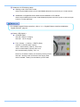
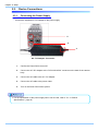
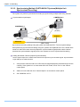
2.3.1.
Connecting the Power Supply
Connect the supplied AC / DC Adaptor to the power supply.
5.
2.
3.
AC / DC Adaptor Connection
1.
Confirm the Power SW is turned off.
2.
Connect the AC / DC Adaptor to the “DC22-32V 65VA” connector on the back of the camera
body.
3.
Connect the AC cable to the AC / DC Adaptor.
4.
Connect the AC cable to the power outlet.
5.
Turn on the Power SW one the system
For the specification of the power supply which can be used, refer to “5.1.2. General
Specifications”, page 45.
14
2.3.2.
Connecting a PC
The system can have the operation of its functions performed from a PC using the Gigabit Ethernet
interface.
This section explains the required setup when connecting the system to a PC.
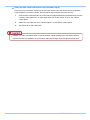
To connect a PC to the system, connect the system to a commercially available
1000BASE-T-compatible interface board with a LAN cable. For the LAN cable, prepare a UTP or
STP CAT5E (enhanced category 5) or higher category LAN cable. (UTP: Unshielded Twisted Pair,
STP: Shielded Twisted Pair)
The maximum cable length between the PC and the system is 100 m (compliant to the 1000BASE-T
specification). One PC can connect to a maximum of 64 Photron Gigabit Ethernet interface
equipped cameras using a hub. When connecting multiple devices, connect through a switching hub
that can connect at 1000BASE-T. The maximum length of the cable that connects the system (or
PC) to the switching hub is also 100 m.
For operating instructions of Photron FASTCAM Viewer software, refer to "Photron FASTCAM
Viewer User's Manual".
2.3.3.
Factory Default Setting
This system can be restored to the factory settings state.
For operating instructions of Photron FASTCAM Viewer software, refer to "Photron FASTCAM
Viewer User's Manual".
15
FASTCAM SA7 Hardware Manual
3.5.
LOW LIGHT Mode
The more you increase the frame rate or shutter speed of the camera, the more the amount of light
entering the camera decreases, making the displayed image darker. Low light mode is a function that
temporarily increases the exposure time, making the displayed image easier to see to enable you to
focus and setup camera.
3.6.
White Balance Adjustment (Color Types Only)
On digital video cameras, photographing white as pure white is described as "having the appropriate
white balance." On the system's color types as well, in order to take images with the correct color
representation, the white balance must be adjusted for the color temperature of the light source used.
The intensity of each color, R, G, and B, can be adjusted on this system. By adjusting the balance of
those three colors to match the light source used, the appropriate white balance can be achieved.
Two methods are available for adjusting the white balance, preset and user-editable white balance.
These methods are explained in this section.
3.6.1.
Using Preset White Balance (Color Types Only)
With the system, there are two types of white balance presets (5100K, 3100K) for use with common
light sources. The suggested color temperature for these presets is listed below.
5100K (Daylight, Outdoors)
3100K (Halogen Light Source)
3.6.2.
Using User White Balance (Color Types Only)
User white balance can be set in order to achieve the most appropriate white balance for the light
source used with the system and the conditions during recording.
The values set here are stored in the camera body's internal memory as the user preset, and they
can be loaded by selecting USER.
There are also two methods for setting user white balance, AUTO USER and EDIT USER.
21
FASTCAM SA7 Hardware Manual
Chapter. 3 Recording
3.7.
Color Enhancement Function (Color Types Only)
Color types feature an image color enhancement setting. The image color enhancement level can be
adjusted in five steps, including the OFF setting.
Display
Contents
OFF
x0.5 (LEVEL1)
x1 (LEVEL2)
Turns the color enhancement mode off
x1.5 (LEVEL3)
x2 (LEVEL4)
S Sets x1.5 color enhancement
3.8.
S Sets x0.5 color enhancement
S Sets x1 (default) color enhancement
S Sets x2 color enhancement
LUT (Look-Up Table) Operations
The LUT (Look-Up Table) refers to a reference table that defines the relationship between the pixel
brightness gradation of the original image data taken and the brightness gradation displayed on a
computer screen or video monitor.
The system contains a hardware LUT function, and you can display the image data taken with
improved contrast (light and dark sharpness) or make an object in the image stand out by
emphasizing a specified gray level range.
The LUT in the system and the relationship between it and video output and the PC software is
explained below.
When an image is saved with its brightness converted with the LUT, the image saved is the image
that has had its brightness converted.
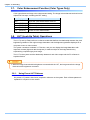
3.8.1.
Using Preset LUT Patterns
Six preset LUT patterns have been prepared in advance on the system. Each of these patterns is
explained in sequence in this section.
22
DEF1: Gain 1x
The input is always linear output.
DEF2: Gamma 0.8
This LUT is 0.8 gamma correction. This LUT is used for normal conditions.
DEF3: Gamma 0.6
This LUT is 0.6 gamma correction.
23
FASTCAM SA7 Hardware Manual
Chapter. 3 Recording
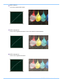
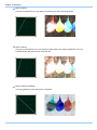
DEF4: Gain 2x
The gain is doubled and you can display the dark areas of the image emphasized.
DEF5: Gain 4x
The gain is quadrupled and you can display the dark areas of the image emphasized. This LUT
emphasizes the dark portions even more than D4.
DEF6: Reverse Gradation
The input gradation is reversed and then displayed.
24
3.8.2.
Using a Custom LUT
Creating a LUT pattern is done with PFV.
For the creation method of a LUT pattern, refer to “Photron FASTCAM Viewer User's Manual”.
3.9.
Edge Enhancement Function
With the system's edge enhancement setting, you can enhance the edges in the recorded image in
three steps.
Display
OFF
Contents
Edge enhancement off.
LEVEL1
Edge enhancement set to light.
LEVEL 2
Edge enhancement set to medium.
LEVEL 3
Edge enhancement set to heavy.
25
FASTCAM SA7 Hardware Manual
Chapter. 3 Recording
3.10. Input / Output Signal Types
With the system, many signals can be input and output through the I/O cable. Signals that can be
input and output from the I/O cable are listed below.
A signal other than the specified signal must not be input to the various connectors.
Use extreme caution as there is a risk of damage to both the input device and the output device.
3.10.1. TRIG TTL IN Connector
The system recognizes an external TTL signal as a trigger during the READY or ENDLESS
recording state. Starting and stopping recording (in the selected recording mode) is controlled with
this signal.
Input voltage is 0V to +10V (L level +1.0 or less, H level +2.8V to +10V), positive or negative polarity,
pulse width is 100 ns or greater.
3.10.2. TRIG TTL OUT Connector
A 5V TTL trigger signal is output for input to an external device.
3.10.3. TRIG SW IN Connector
This trigger is input during the READY or ENDLESS recording state by contact between the BNC
connector's shield and a center pin (switch closure). The center pin normally has voltage flowing
through it. Use caution to avoiding contact with other pins.
3.10.4. SYNC IN Connector
The system recognizes a TTL signal from other devices as a synchronization signal.
Input voltage is 0V to +10V (L level +1.0 or less, H level +2.8V to +10V), positive or negative polarity,
pulse width is 100 ns or greater.
26
3.10.5. GENERAL IN Connector
The effect when a signal is input is described below, and can be optionally selected and set. The
setting is made from the PFV.
The input voltage is 0V to +10V (L level +1.0 or less, H level +2.8V to +10V), positive or negative
polarity, pulse width is 100 ns or greater.
TRIG POS/NEG
READY POS/NEG
Inputs a TTL trigger signal.
Inputs a change recording ready status signal (READY ON/OFF).
To make the setting from PFV, refer to the “Photron FASTCAM Viewer User’s Manual”.
3.10.6. GENERAL OUT (1, 2) Connector
These are also BNC connectors. The signals below can be changed and output from the PFV.
SYNC POS/NEG
EXPOSE POS/NEG
REC POS/NEG
TRIG POS/NEG
READY POS/NEG
(POS: positive polarity, NEG: negative)
Outputs a vertical synchronization signal.
Outputs the camera's exposure period signal.
* Outputs during both LIVE and recording.
Outputs a signal during recording.
Outputs the trigger signal the camera received.
Outputs a signal that indicates the recording ready state.
Refer to “3.13.2. GENERAL OUT Signal Settings”, page 36 for details.
27
FASTCAM SA7 Hardware Manual
Chapter. 3 Recording
3.11. Using External Triggers
With the system, you can record by receiving various trigger signals matched to the recording
application. The trigger signals that can be used on the system are explained here, along with a
description of how to use them.
3.11.1. Inputting an External Trigger Signal
The external trigger signals that can be used with the system and their input system are listed below.
You can change External trigger signal input settings by PFV.
The signals input from the TRIG TTL IN and GENERAL IN connectors are explained in section
"2.2.5. I/O Port Connector".
Connector Name
(Input System)
Setting
TRIG POS
FET Input 0V - +10V (L level +1.0 or less, H level
+2.8V to +10V), Positive Polarit
TRIG NEG
FET Input 0V - +10V (L level +1.0 or less, H level
+2.8V to +10V), Negative Polarity
TRIG POS
FET Input 0V - +10V (L level +1.0 or less, H level
+2.8V to +10V), Positive Polarity
TRIG NEG
FET Input 0V - +10V (L level +1.0 or less, H level
+2.8V to +10V), Negative Polarity
TRIG TTL IN
GENERAL IN
TRIG SW IN
Signal
None
Contact signal
Set the signal type to be input to GENELAL IN from the PFV in advance.
Use caution not to input more than specified voltage to the TRIG TTL IN and GENERAL IN
trigger signal inputs as there is a risk of damage to the equipment.
For the setting method of the signal inputted into GENERAL IN, refer to “3.13.1. GENERAL IN
Signal Settings”, page 35.
28
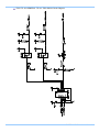
TRIG TTL IN / GENERAL TTL IN / TRIG SW IN Circuit Diagram
29
FASTCAM SA7 Hardware Manual
Chapter. 3 Recording
3.11.2. Outputting External Trigger Signals
With the system, you can externally output trigger signals. Output is performed with the TRIG TTL
OUT connector's dedicated trigger output system provided by the system, and additionally, output
can also be optionally set from the GENERAL OUT connector. You can change External trigger
signal output settings by PFV.
Signal output is performed from the TRIG TTL OUT connector and the GENERAL OUT connector
explained in section “2.2.5. I/O Port Connector”.
The chart below summarizes the output systems and the signals that can be output.
Connector Name
(Output System)
Setting
Signal Type
TRIG POS
TTL, SW, SOFT, all TRIG pulse output
CMOS (74ACT541 buffer) output,
Positive Polarity.
Approx.24 usec for
TRIG SW IN
TRIG NEG
TTL, SW, SOFT, all TRIG pulse output
CMOS (74ACT541 buffer) output,
Negative Polarity.
Approx. 85 ns for TRIG
TTL IN, GENERAL IN
TRIG TTL OUT
TTL IN THRU
POS
TRIG TTL IN through output
CMOS (74ACT541 buffer) output,
Positive Polarity.
TTL IN THRU
NEG
TRIG TTL IN through output
CMOS (74ACT541 buffer) output,
Negative Polarity.
Delay Time
Approx. 85 ns for TRIG
TTL IN
TRIG POS
TTL, SW, SOFT, all TRIG pulse output
CMOS (74ACT541 buffer) output,
Positive Polarity.
Approx. 24 usec for
TRIG SW IN
TRIG NEG
TTL, SW, SOFT, all TRIG pulse output
CMOS (74ACT541 buffer) output,
Negative Polarity
Approx. 85 ns for TRIG
TTL IN, GENERAL IN
GENERAL OUT
When a trigger signal is output to GENERAL OUT, set the signal to be output from the PFV in
advance before using it.
30
3.12. Using External Synchronization Signals
An external synchronization mode to synchronize to an external signal is provided on the system. By
using an external synchronization signal, recording can be conducted using multiple cameras to
synchronize the timing of the shots or to also synchronize the shots with external measuring devices
and lighting. The procedure and precautions for using the external synchronization signal are
explained below.
3.12.1. Inputting an External Synchronization Signal
An external synchronization signal can be input with the system. See the chart below for external
synchronization input settings.
Display
Contents
Signal (Input Signal Conditions)
OFF
Sets external synchronization off, operates
independently.
(none)
ON CAM POS
Synchronizes to a positive polarity signal
from the system.
FET Input 0V - +10V (L level
+1.0 or less, H level +2.8V to
+10V), Positive Polarity
ON CAM NEG
Synchronizes to a negative polarity signal
from the system.
FET Input 0V - +10V (L level
+1.0 or less, H level +2.8V to
+10V), Negative Polarity
3.12.2. Outputting an External Synchronization Signal
The system can externally output a synchronization signal. Output of the external synchronization
signal is performed from the GENERAL OUT connector explained in section“2.2.5. I/O Port
Connector”. See the chart below for external synchronization output settings.
Display
Contents
Signal Type
Delay Time
SYNC POS
Outputs a positive polarity
vertical synchronization signal.
CMOS (74ACT541 buffer)
output, positive polarity
Approx. 253nsec
SYNC NEG
Outputs a negative polarity
vertical synchronization signal.
CMOS (74ACT541 buffer)
output, negative polarity
Approx. 288nsec
31
FASTCAM SA7 Hardware Manual
Chapter. 3 Recording
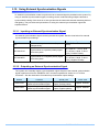
3.12.3. Synchronizing Multiple FASTCAM SA7 Systems(Multiple Unit
Synchronized Recording)
The system can perform synchronized recording by synchronizing multiple units using external.
Synchronization input/output
CAMERA No.2
CAMERA No.1
(SLAVE)
SYNC IN
(MASTER)
SYNC OUT
(BNC Cable)
Synchronized recording settings using the system are made with PFV. The conceptual settings
when performing synchronized recording using two systems are explained here. First, decide which
camera to make the master camera (outputs the synchronization signal) and the slave camera
(receives the synchronization signal) from the two systems to use for synchronized recording.
Setting the Master Camera (Outputs Synchronization)
Set the signal output for the master camera which will output the synchronization signal. Synchronization
signal settings are made with PFV.
1.
Verify that the camera mode is in LIVE mode (the image displayed is passed through from the
camera). If the system is in a mode other than LIVE mode, check "Live" on the camera
control panel.
2.
Select I/O on the left tree from "Camera Option" on the camera control panel.
3.
Set "GENERAL OUT1".
32
Setting the Slave Camera (Receives the Synchronization Signal)
Next, set the synchronization signal input for the slave camera which will receive the synchronization
signal supplied by the master camera. Synchronization signal settings are made with PFV.
1.
Verify that the camera mode is in LIVE mode (the image displayed is passed through from the
camera). If the system is in a mode other than LIVE mode, check "Live" on the camera
control panel.
2.
Select I/O on the left tree from "Camera Option" on the camera control panel.
3.
Set SYNC IN to "ON CAM POS".
If steps, 2 to 3 are completed when no synchronization signal is being input, the camera will not
operate normally. As detailed in the procedure, make the settings when the signal is being input.
33
FASTCAM SA7 Hardware Manual
Chapter. 3 Recording
3.12.4. Synchronizing the System with Other Cameras (Mixed Device
Synchronized Recording)
Mixed-type synchronized recording can be performed with Photron's other high-speed cameras
(except for some older products).
Basic Process
1.
Decide the master camera (the source of the synchronization signal) and the slave camera
(the camera that will operate according to the synchronization signal from the master).
Basically, by making the master camera the camera with the lowest maximum frame rate that
can be set, you can avoid setting a synchronization signal speed the slave camera cannot
receive.
2.
Connect the master camera's V-SYNC output connector to the slave camera's V-SYNC input
connector with a BNC cable, select the synchronization signal output polarity on the master
camera, and then set the slave camera to be operated by that signal.
For camera types that can perform synchronized recording or for detailed instructions on making
the settings, contact Photron at the contact information in "7.1. Contact Information"
If you want to synchronize FASTCAM SA7 with other camera model, miss-synchronization may
occurs due to different of exposure timing between FASTCAM SA7 and other camera model.
Please contact us if you have a question for this issue.
34
3.13. GENERAL Signal Settings
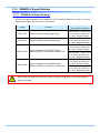
3.13.1. GENERAL IN Signal Settings
Details of the signals output from the GENERAL OUT connector explained in section “3.10. Input /
Output Signal Types” are shown in the chart below.
Display
Contents
Signal
(Input Signal Conditions)
TRIG POS
Inputs a positive polarity trigger signal.
FET Input 0V - +10V (L level
+1.0 or less, H level +2.8V
to +10V), Positive Polarity
TRIG NEG
Inputs a negative polarity trigger signal.
FET Input 0V - +10V (L level
+1.0 or less, H level +2.8V
to +10V), Negative Polarity
READY POS
READY NEG
Inputs a positive polarity READY signal.
READY ON/OFF is switched by a pulse input.
Inputs a negative polarity READY signal.
READY ON/OFF is switched by a pulse input.
FET Input 0V - +10V (L level
+1.0 or less, H level +2.8V
to +10V), Positive Polarity
FET Input 0V - +10V (L level
+1.0 or less, H level +2.8V
to +10V), Negative Polarity
FET Input 0V - +10V (L level
+1.0 or less, H level +2.8V
to +10V), Positive Polarity
FET Input 0V - +10V (L level
+1.0 or less, H level +2.8V
to +10V), Negative Polarity
When using the camera as a part of a system, verify the characteristics of the input signals
before using them.
35
FASTCAM SA7 Hardware Manual
Chapter. 3 Recording
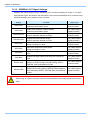
3.13.2. GENERAL OUT Signal Settings
Details of the signals output from the GENERAL OUT connector explained in section “3.10. Input /
Output Signal Types” are shown in the chart below. There are three GENERAL OUT connectors and
individual settings can be made for each connector.
Display
Contents
Signal Type
SYNC POS
SYNC POS Outputs a positive polarity
vertical synchronization signal.
+5V CMOS Output
Positive Polarity
SYNC NEG
SYNC NEG Outputs a negative polarity
vertical synchronization signal.
+5V CMOS Output
Negative Polarity
EXPOSE POS
Outputs the camera head's image
sensor's exposure interval at H level.
+5V CMOS Output
Positive Polarity
EXPOSE NEG
Outputs the camera head's image
sensor's exposure interval at L level.
+5V CMOS Output
Negative Polarity
REC POS
REC POS Outputs an interval signal
during recording at H level.
+5V CMOS Output
Positive Polarity
REC NEG
REC NEG Outputs an interval signal
during recording at L level.
+5V CMOS Output
Negative Polarity
TRIG POS
Outputs the trigger signal received by the camera at H
level.
+5V CMOS Output
Positive Polarity
TRIG NEG
Outputs the trigger signal received by the camera at L
level.
+5V CMOS Output
Negative Polarity
READY POS
Outputs a signal at H level during the trigger wait state.
(READY in START mode.) Only valid during START,
CENTER, END, and MANUAL modes.
+5V CMOS Output
Positive Polarity
READY NEG
Outputs a signal at L level during the trigger wait state.
(ENDLESS recording state in CENTER, END, MANUAL)
Only valid during START, CENTER, END, and MANUAL
modes.
+5V CMOS Output
Negative Polarity
When using as a part of a system, verify the characteristics of the output signals before using
them.
36
3.14. Signal Delay
With the system, you can set the signal delay time or pulse width for the various signals that are input
and output. Pulse width and delay settings for the various signals to input/output are made with PFV.
The content of each setting is listed in the chart below.
Setting Item
TRIG TTL IN DELAY
SYNC IN DELAY
Setting Range (Value)
0-60 (s) 100 ns units
0-1/frame rate (s) 100 ns units
GENERAL IN DELAY
0-60 (s) 100 ns units
TRIG OUT WIDTH
0-1 (ms) 100 ns units
SYNC OUT DELAY
0-1/frame rate (s) 100 ns units
SYNC OUT WIDTH
0-500 (us), 1/frame rate (s) at 2000 fps or higher 100 ns units
EXPOSE OUT DELAY
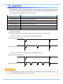
SYNC OUT TIMES
0-1/frame rate (s) 100 ns units
0.5, 1, 2, 4, 6, 8, 10, 20, 30 ( * x1 is standard output)
SYNC OUT TIMES
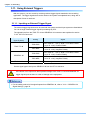
Outputs SYNC (vertical synchronization signal) from SYNC OUT that is X times SYNC.
Example: For a frame rate of 1000 fps, SYNC OUT TIMES setting of 2.
1000 fps Synchronization Signal
SYNC OUT Output
Example: For a frame rate of 1000 fps, SYNC OUT TIMES setting of 4.
1000 fps Synchronization Signal
SYNC OUT Output
An accurate frequency is output, but when SYNC OUT TIMES is set to a large value with a high
frame rate, the setting may result in frequency errors.
37
FASTCAM SA7 Hardware Manual
Chapter. 3 Recording
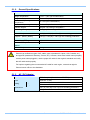
3.15. Using USER SW (Programmable Switch)
There is a switch that can be set on the back of the system. A setting for the switch is made from the
PFV and it can be assigned a different function. As an example, setting the “USER SW” switch on the
back of the camera body is explained here.
Setting
Explanation
OFF
Does not assign a function.
Change Frame Rate
Raises the frame rate
Change Resolution
Lowers the resolution
Change Shutter Speed
Increases the shutter speed.
Change Trigger Mode
Changes the trigger mode.
Fitting image
Adjusts the size of the image displayed on the video output to be the
maximum for the current resolution.
Status Display
Displays the status of camera settings on the video output.
Switch LIVE/MEMORY
Switches between LIVE and MEMORY states.
Record Ready
Sets the record ready state.
Record
Starts recording.
Low-Light
Turns low-light mode ON/OFF.
38
Chapter. 4 Connecting a PC
4.1. Connecting the Gigabit Ethernet Interface to a PC
39
FASTCAM SA7 Hardware Manual
Chapter. 4 Connecting a PC
4.1.
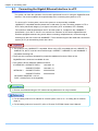
Connecting the Gigabit Ethernet Interface to a PC
The system can have the operation of its functions performed from a PC using the Gigabit Ethernet
interface. This section explains the required setup when connecting the system to a PC.
To connect a PC to the system, connect the system to a commercially available
1000BASE-T-compatible interface board with a LAN cable. For the LAN cable, prepare a UTP or
STP Cat 5e (enhanced category 5) or higher LAN cable. (UTP: unshielded, STP: shielded)
The maximum cable length between the PC and the system is, compliant to the 1000BASE-T
specification, up to 100 m. One PC can connect to a maximum of 64 Photron Gigabit Ethernet
interface equipped cameras using a hub. When connecting multiple devices, connect through a
switching hub that can connect at 1000BASE-T. The maximum length of the cable that connects the
system (or PC) to the switching hub is also 100 m.
The system is only 1000BASE-T compatible. When using a PC compatible with only 10BASE-T or
100BASE-TX, the PC must be connected through a 10BASE-T, 100BASE-TX, and 1000BASE-T
compatible switching hub.
There are two connectors equipped for prospective additional functions. Either of the
GigabitEthernet connectors is available for use.
The system's factory default IP address is below:
IP ADDRESS > GIGABIT ETHER1
192.168.0.10
GIGABIT ETHER2
192.168.1.10
GIGABIT ETHER 1
255.255.255.0
GIGABIT ETHER 2
255.255.255.0
NETMASK >
GATEWAY ADDRESS > 0.0.0.0
PORT > 2000 (Fixed, not changeable)
Photron recommends using an STP cable over long distances or in noisy locations.
For the setting method of IP address for camera system, refer to “4.1.2. Setting the IP Address”,
page 41.
For the setting method of control PC, refer to “Photron FASTCAM Viewer User's Manual”.
40
4.1.1.
Connecting the System and a PC
Connect the LAN cable to the system as shown below.
Insert the LAN cable into the "GIGABIT ETHER 1" connector.
4.1.2.
Setting the IP Address
When connecting the system to a PC or when connecting other Gigabit Ethernet interface
compatible Photron cameras, set each of those devices to a different IP address. Also, when
connecting the system to an existing network, do not use IP addresses that are already in use on
the network.
For the procedure for setting the IP address of the system, refer to the "Photron FASTCAM Viewer
User's Manual".
41
FASTCAM SA7 Hardware Manual
Chapter. 4 Connecting a PC
4.1.3.
Connecting Multiple Systems and a PC
With PFV, the system’s control software, one PC can connect to and control multiple FASTCAM
SA5,FASTCAM SA4 ,FASTCAM 2 ,FASTCAM 1.1, FASTCAM SA7, FASTCAM APX-RS, and
FASTCAM MH4-10K systems.
When connecting to multiple systems, set the IP address of each one to a unique setting.
4.1.4. Gigabit Ethernet Interface Initialization
When encounter problems on communication between the control software PFV and the camera,
please perform the following steps to initialize the Gigabit Ethernet interface.
1.
Press and hold on the USER SW (Programmable Switch) on the rare of camera for about
10~15 seconds.
2.
When the LEDs blink from left to right and then from right to left alternately, it indicates the
initialization operation is accomplished.
Pressing and holding on the USER SW (Programmable Switch) for more than 15 seconds will result
in an IP Address Initialization.
4.1.5. Camera IP Address Initialization
In some circumstance when the IP address is changed, and the new IP address is not explicit, an IP
Address Initialization operation is recommended. In this case, the IP address will be reset to
192.168.0.10 as the factory settings.
1.
Press and hold on the USER SW (Programmable Switch) on the rare of camera for over 15
seconds.
2.
When the LEDs blink from left to right and then from right to left alternately, it indicates the
initialization operation is accomplished.
42
Chapter. 5 Product Specifications
5.1. Specifications
5.2. Dimensions
43
FASTCAM SA7 Hardware Manual
Chapter. 5 Product Specifications
5.1.
Specifications
5.1.1.
Product Specifications
30K type
Image Sensor
Sensor Resolution (full)
Max. Full Frame Rate
Max. Frame Rate
1,280x1,024 pixels
3,500 fps (1,280x1,024)
2,000 fps (1,280x1,024)
30,000 fps (320x256)
15,000 fps (320x256)
Min. Frame Rate
60 fps (1,280x1,024)
Sensor Size
12.80 mm x 10.24 mm
Pixel Size
Recording
Color Depth
15K type
CMOS image sensor
10m x 10um
Monochrome
Color
12-bit A/D conversion
36-bit A/D conversion (RGB each 12-bit) Bayer color filter method
Shutter
Electronic shutter
Recording Method
IC memory
Recording Memory Amount
4 GB standard, 8 GB maximum
Trigger Method
Gain Control
Image Output Customization
Start, Center, END, Manual
Hardware LUT on camera, controllable via software
Customizable LUT, brightness is changeable
Ext. Sync. Input Signal
5Vp-p negative polarity/positive polarity (switchable)
Ext. Sync. Output Signal
5Vp-p negative polarity/positive polarity (switchable)
Trigger Input Signal
TTL, contact
Other Output Signals
Other timing signal outputs
External Control
digital I/F (PC)
Video Output Signal
Digital Interface
N/A
Gigabit Ethernet (1000BASE-T) x2
44
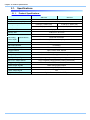
5.1.2.
General Specifications
Environment Conditions
Strage Temperature
-20℃ ~ 60℃ (No Condensation)
Strage Humidity
Below 85% (No Condensation)
Guaranteed Operating
Temperature
0~40℃ (No Condensation)
Guaranteed Operating Humidity
Below 85% (No Condensation)
Pollution degree
Degree 2 according to IEC60664-1
Categoey Ⅱaccording to IEC60664-1
Overvoltage category
Dimensions
Camera Body
135 (H) × 102 (W) × 195.2 (D) mm excluding protrusions
Camera + Memory Battery
135 (H) × 138 (W) × 195.2 (D) mm excluding protrusions
DC Power Supply
Power Supply Voltage
22V ~ 32V
Power Consumption
65VA
Weight
Camera Body
3.6kg
Photron has verified two types of AC cables, type A (standard for Japan, USA, Canada, etc.)
and type SE (standard for Germany, France, etc.). However, when those cables cannot properly
receive power when plugged in, use the proper AC cable for the region's standards and verify
that AC cable works properly.
For inquires regarding the recommended AC cable for each region, contact that region's
Photron branch office or the distributor.
5.1.3.
AC / DC Adaptor
Manufacurer
FSP Group Inc. (Brand Name : PROTEK)
Type
PMP150-14-K20
Input
AC100-240V , 47-63Hz , 1.63-0.7A
Output
Dimensions
DC24V , 6.25A
49.7 (H)×82 (W)×207.6 (D) mm excluding protrusions
Weight
970g
Rating
45
FASTCAM SA7 Hardware Manual
Chapter. 5 Product Specifications
5.1.4.
Options
User Options
4 output trigger box
Spare power supply connector (for a custom cable)
Dust-proof cover for the LAN connector
Dedicated carry case
Memory backup battery
46
47
FASTCAM SA7 Hardware Manual
Chapter. 5 Product Specifications
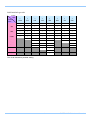
5.1.5.
Frame Rate and Resolution
FASTCAM SA7 type 30K
Image
Size
1,280
×
1,024
1,280
×
512
1,280
×
256
1,280
×
128
320
×
256
896
×
896
704
×
704
640
×
584
60
○
○
○
○
○
○
○
○
125
○
○
○
○
○
○
○
○
250
○
○
○
○
○
○
○
○
500
○
○
○
○
○
○
○
○
1,000
○
○
○
○
○
○
○
○
2,000
○
○
○
○
○
○
○
○
2,500
○
○
○
○
○
○
○
○
3,500
○
○
○
○
○
○
○
○
4,000
○
○
○
○
○
○
○
5,000
○
○
○
○
○
○
○
7,500
○
○
○
10,000
○
○
○
○
○
Frame
Rate
15,000
30,000
○
The circle indicates a possible setting.
48
○
○
○
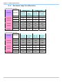
FASTCAM SA7 type 15K
Image
Size
1,280
×
1,024
1,280
×
512
1,280
×
256
1,280
×
128
320
×
256
896
×
896
704
×
704
640
×
584
60
○
○
○
○
○
○
○
○
125
○
○
○
○
○
○
○
○
250
○
○
○
○
○
○
○
○
500
○
○
○
○
○
○
○
○
1,000
○
○
○
○
○
○
○
○
2,000
○
○
○
○
○
○
○
○
○
Frame
Rate
2,500
○
○
○
3,500
○
○
○
○
4,000
○
○
○
○
5,000
○
○
○
○
○
○
7,500
10,000
○
15,000
○
○
○
○
○
The circle indicates a possible setting.
49
FASTCAM SA7 Hardware Manual
Chapter. 5 Product Specifications
5.1.6.
Recordable Image Count/Resolution
FASTCAM SA7 type 30K
4 GB Memory Type
Resolution
Frame Rate
Rec. Time
(seconds)
8 GB Memory Type
Rec.
Frames
(number)
Rec. Time
Rec. Frames
(seconds)
(number)
1,280×1,024
3,500 fps
0.623
2,180
1.247
4,365
1,280×512
5,000 fps
0.872
4,361
1.746
8,730
1,280×256
10,000 fps
0.872
8,722
1.746
17,460
1,280×128
15,000 fps
1.163
17,444
2.328
34,920
320×256
30,000 fps
1.163
34,888
2.328
69,841
896x896
5,000 fps
0.712
3,560
1.425
7,126
704x704
7,500 fps
0.769
5,766
1.539
11,543
640x584
10,000 fps
0.765
7,646
1.531
15,307
FASTCAM SA7 type 15K
Memory 4 GB Type
Resolution
Frame Rate
Memory 8 GB Type
Rec. Time
Rec. Frames
Rec. Time
Rec. Frames
(seconds)
(count)
(seconds)
(count)
1,280×1,024
2,000 fps
1.090
2,180
2.183
4,365
1,280×512
2,500 fps
1.744
4,361
3.492
8,730
1,280×256
5,000 fps
1.744
8,722
3.492
17,460
1,280×128
7,500 fps
2.326
17,444
4.656
34,920
320×256
15,000 fps
2.326
34,888
4.656
69,841
896x896
2,500 fps
1.424
3,560
2.850
7,126
704x704
3,500 fps
1.647
5,766
3.298
11,543
640x584
5,000 fps
1.529
7,646
3.061
15,307
50
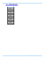
5.1.7.
Shutter Speed List
Setting Value
1/125
1/250
1/500
1/1,000
1/1,600
1/2,000
1/2,500
1/4,000
1/5,000
1/8,000
1/10,000
1/25,000
1/50,000
1/100,000
51
FASTCAM SA7 Hardware Manual
Chapter. 5 Product Specifications
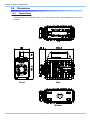
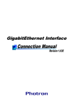
5.2.
5.2.1.
Dimensions
Camera Body
All dimensions are in millimeters (mm) – 25.4 mm equals one inch. These diagrams are not shown
to scale.
Top
40.2
195.2
151.2
45
102
F AST C A M S A7
Front
IP ADDRESS 1
192.168.000.010
IP ADDRESS 2
192.168.001.010
NETWORK MASK 1
255.255.255.000
NETWORK MASK 2
255.255.255.000
Side
Bottom
52
5.2.2.
AC / DC Adaptor
All dimensions are in millimeters (mm) – 25.4 mm equals one inch. These diagrams are not shown
to scale.
82.0
1219±50
LED INDICATOR
207.6
49.7
AC INPUT, IEC 320/C14 INLET(Class Ⅰ)
190.2
58.8
53
RUBBER FOOT
FASTCAM SA7 Hardware Manual
Chapter. 5 Product Specifications
54
Chapter. 6 Warranty
6.1. About the Warranty
55
FASTCAM SA7 Hardware Manual
Chapter. 6 Warranty
6.1.
About the Warranty
This system has been shipped having undergone rigorous testing. However, in the unlikely event that
it malfunctions due to a manufacturing defect, it will be repaired, at no charge, within the warranty
period.
Warranty Exceptions
The following exceptions will result in fee-based repair, even within the warranty period.
1.
Damage or malfunction as a result of fire, earthquake, water damage, lightning, other natural
disasters, pollution, or the effects of abnormal voltage.
2.
Damage or malfunction as a result of dropping or mishandling during shipment or when
moving after purchase or misuse.
3.
Consumable goods (cables)
4.
When repair, adjustment, or alternation done by an entity other than Photron service has
been performed on the system, or damage or malfunction that is determined to be attributed
to a fault in the use the product.
For inquires related to malfunction, contact the dealer where the product was purchased, or the
nearest Photron office.
Reference
For inquires related to our product, refer to "7.1. Contact Information", page 58.
56
Chapter. 7
Contacting Photron
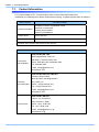
7.1. Contact Information
57
FASTCAM SA7 Hardware Manual
Chapter. 7 Contacting Photron
7.1.
Contact Information
For inquires related to PFV, contact Photron at the contact information listed below.
Additionally, the following items will be verified when inquiring, so please prepare them in advance.
Items Verified
Concrete Example
Contact Information
Company, school or organization name,
customer contact name,
contact phone number,
contact e-mail address.
Product Name
FASTCAM SA7
Serial Number
Check on the nameplate seal.
Condition of the system and what is known about it.
Contact Information
PHOTRON USA, INC.
9520 Padgett Street, Suite 110
In Americas
and Antipodes
San Diego, CA 92126-4426, USA
Phone : 800-585-2129 or 858-684-3555
Fax : 858-684-3558
E-mail : [email protected]
www.photron.com
PHOTRON EUROPE LIMITED
The Barn, Bottom Road,
West Wycombe, Buckinghamshire,
In Europe,
Africa and India
HP14 4BS, U.K.
Phone : +44(0) 1494 48 1011
Fax : +44(0) 1494 48 7011
E-mail : [email protected]
www.photron.com
PHOTRON LIMITED
Fujimi 1-1-8, Chiyoda-Ku
Tokyo 102-0071, Japan
In other areas
Phone : +81 3 3238 2107
Fax : +81 3 3238 2109
E-mail : [email protected]
www.photron.co.jp
58
FASTCAM SA7
Hardware Manual
Revision 1.00E
Publication Date
February, 2012
Publisher
PHOTRON LIMITED
Chiyoda Fujimi Bldg., Fujimi 1-1-8, Chiyoda-ku, Tokyo 102-0071
© 2012.PHO T RON LIMIT ED, All rights reserved. Printed i n Japa n.
(Control No. E120208100158U)