1
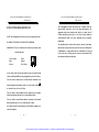
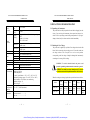
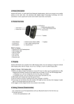
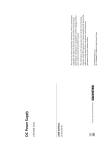
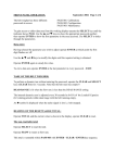
Artisan Technology Group is your source for quality new and certified-used/pre-owned equipment • FAST SHIPPING AND DELIVERY • TENS OF THOUSANDS OF IN-STOCK ITEMS • EQUIPMENT DEMOS • HUNDREDS OF MANUFACTURERS SUPPORTED • LEASING/MONTHLY RENTALS • ITAR CERTIFIED SECURE ASSET SOLUTIONS SERVICE CENTER REPAIRS Experienced engineers and technicians on staff at our full-service, in-house repair center WE BUY USED EQUIPMENT Sell your excess, underutilized, and idle used equipment We also offer credit for buy-backs and trade-ins www.artisantg.com/WeBuyEquipment InstraView REMOTE INSPECTION LOOKING FOR MORE INFORMATION? Visit us on the web at www.artisantg.com for more information on price quotations, drivers, technical specifications, manuals, and documentation SM Remotely inspect equipment before purchasing with our interactive website at www.instraview.com Contact us: (888) 88-SOURCE | [email protected] | www.artisantg.com PST-3201/3202 PROGRAMMABLE POWER SUPPLY USER MANUAL Declaration of Conformity We GOOD WILL INSTRUMENT CO., LTD. No. 95-11, Pao-Chung Rd., Hsin-Tien City, Taipei Hsien, Taiwan declares that the below mentioned product PST-3201, PST-3202 are herewith confirmed to comply with the requirements set out in the Council Directive on the Approximation of the Law of Member States relating to Electromagnetic Compatibility (89/366/EEC, 92/31/EEC, 93/68/EEC) and Low Voltage Equipment Directive (73/23/EEC). For the evaluation regarding the Electromagnetic Compatibility and Low Voltage Equipment Directive, the following standards were applied: ◎ EMC EN 61326-1: Electrical equipment for measurement, control and laboratory use –– EMC requirements (1997+A1: 1998) Conducted and Radiated Emissions EN 55011: 1991+A1: 1997+A2: 1996 Current Harmonic EN 61000-3-2: 1995+A1: 1998+A2: 1998 +A14: 2000 Voltage Fluctuation EN 61000-3-3: 1995 ------------------------------------------------------------------------- Electrostatic Discharge EN 61000-4-2: 1995 Radiated Immunity EN 61000-4-3: 1996 Electrical Fast Transients EN 61000-4-4: 1995 Surge Immunity EN 61000-4-5: 1995 Conducted Susceptibility EN 61000-4-6: 1996 Voltage Dips/ Interrupts EN 61000-4-11: 1994 ◎ Safety Low Voltage Equipment Directive 73/23/EEC & amended by 93/68/EEC EN 61010-1: 1993+A2: 1995 IEC 1010-1: 1990+A2: 1995 USA : UL 3111-1 – First Edition, June 1994 Canada: CSA-C22.2 No. 1010.1-92 Artisan Technology Group - Quality Instrumentation ... Guaranteed | (888) 88-SOURCE | www.artisantg.com ii PST-3201/3202 PROGRAMMABLE POWER SUPPLY PST-3201/3202 PROGRAMMABLE POWER SUPPLY USER MANUAL CONTENTS PAGE 1. PRODUCT INTRODUCTION................................................. 1 1-1. Description… … … … … … … … … … … … … … … … … … 1 1-2. Feature… … … … … … … … … … … … … … … … … … … ... 1 2. TECHNICAL SPECIFICATIONS… … … … … … … … … … 3 3. PRECAUTIONS BEFORE OPERATION… … .… … … … ... 5 3-1. Unpacking the Instrument… … … … … … .… … … … .… . 5 3-2. Checking the Line Voltage… … … … … … … ..… … … … . 5 3-3. Environment… … … … … … … … … … … … … … ..… … ... 6 4. PANEL INTRODUCTION… … … … … … … … ..… … … … ... 7 5. OPERATION METHOD… … … … … … … … … … … … ...… . 11 5-1. Output Voltage/Current Setting… … … … … … … ..… … 11 5-2. Over Voltage/Current Protection Setting… … … … … ... 12 5-3. Voltage/Current Step Setting… … … … … … … … … … .. 13 5-4. Information Storing & Recalling Setting… … … … … … 13 5-5. Information Editing & Copying Setting… … … … … … . 15 5-6. Auto Operation Mode… .… … … … … … … … … … … … . 16 5-7. Parallel Operation Mode… … … … … … … … … … … .… . 17 5-8. Track Operation Mode… … … … … … … … … … … … … 17 5-9. GPIB/RS-232 Interface Setting… … … … … … … … … … 18 5-10.The Maximum Output Setting… … … … … … … … … .... 19 5-11.Test Lead… … … … … … … … … … … … … … … … … … .. 20 5-12. The Setting of the GPIB and RS232 Interface… … … .. 20 6. MAINTENANCE… … … … … … … … … ..… … … … … … … .. 21 6-1. Fuse Replacement… … … … … … … … … … … … … … … . 21 6-2. Line Voltage Conversion… … … … … … … … … … … … .. 21 6-3. Adjustment and Calibration… … … … … … … … … … … 22 6-4. Cleaning… … … … … … … … … … … … … … … … … … … 28 7. THE SYSTEM DIAGRAM AND DESCRIPTION… … … .. 29 7-1.Block Diagram… … … … … … … … … … … … … … … … ... 29 7-2.The Operation of the whole circuit… … … … … … … … ... 30 i USER MANUAL SAFETY TERMS AND SYMBOLS These terms may appear in this manual or on the product: WARNING. Warning statements identify condition or practices that could result in injury or loss of life. CAUTION. Caution statements identify conditions or practices that could result in damage to this product or other property. The following symbols may appear in this manual or on the product: DANGER ATTENTION Protective Earth (ground) Frame or Chassis High Voltage refer to Manual Conductor Terminal Terminal Artisan Technology Group - Quality Instrumentation ... Guaranteed | (888) 88-SOURCE | www.artisantg.com ii Terminal PST-3201/3202 PROGRAMMABLE POWER SUPPLY PST-3201/3202 PROGRAMMABLE POWER SUPPLY USER MANUAL FOR UNITED KINGDOM ONLY NOTE: This lead/appliance must only be wired by competent persons WARNING: THIS APPLIANCE MUST BE EARTHED IMPORTANT: The wires in this lead are coloured in accordance with the following code: Green/ Yellow: Blue: Brown: USER MANUAL This cable/appliance shoul d be protected by a suitably rated and approved HBC mains fuse: refer to the rating information on the equipment and/or user instructions for details. As a guide, cable of 0.75mm2 should be protected by a 3A or 5A fuse. Larger conductors would normally require 13A types, depending on the connection method used. Any moulded mains connector that requires removal /replacement must be destroyed by removal of any fuse & fuse carrier and disposed of immediately, as a plug with bared wires is hazardous if a engage d in live socket. Any re-wiring must be carried out in accordance with the information detailed on this label. Earth Neutral Live (Phase) As the colours of the wires in main leads may not correspond with the colours marking identified in your plug/appliance, proceed as follows: The wire which is coloured Green & Yellow must be connected to the Earth terminal marked with the letter E or by the earth symbol or coloured Green or Green & Yellow. The wire which is coloured Blue must be connected to the terminal which is marked with the letter N or coloured Blue or Black. The wire which is coloured Brown must be connected to the terminal marked with the letter L or P or coloured Brown or Red. If in doubt, consult the instructions provided with the equipment or contact the supplier. iii Artisan Technology Group - Quality Instrumentation ... Guaranteed | (888) 88-SOURCE | www.artisantg.com iv PST-3201/3202 PROGRAMMABLE POWER SUPPLY PST -3201/3202 PROGRAMMABLE POWER SUPPLY USER MANUAL USER MANUAL 1. PRODUCT INTRODUCTION 1-1.Description PST-series Programmable Power Supply is controlled by Micro Processor Unit (MPU) that can easily connect communication interface R S-232 or GPIB to computer in order to satisfy users’ demand for auto-testing and auto-control. The voltage and current are completely controlled by 12 bits D/A Converter with higher resolution and accuracy. Also, the digitalization of system makes a speedy, precise and convenient input of information controlled by keyboard. The adjustment of voltage/current is made by software calibration without manual error that will increase the preciseness of the instrument. The function of Over Voltage Protection (OVP) and Over Current Protection (OCP) is set with software and detected with hardware to achieve protected function precisely and speedily in order to secure users from danger by using the instrument. 1-2. Feature 1) An overall digitalization of programmable interface with high resolution. 2) The 192×128 LCD Display can appear multiple settings and measurement results simultaneously.(The display mode is changeable). v 1 Artisan Technology Group - Quality Instrumentation ... Guaranteed | (888) 88-SOURCE | www.artisantg.com PST -3201/3202 PROGRAMMABLE POWER SUPPLY PST -3201/3202 PROGRAMMABLE POWER SUPPLY USER MANUAL 3) Intuitional, intelligent interface window display is convenient for user to operate the instrument. 4) High stability and low draft. 5) The function of over voltage/current/temperature protection. 6) Intelligent control fan (Vary with different output power.) 7) Warning signal by the built-in Buzzer. 8) Step by step calibration procedure. 9) Brand new panel design and the 1/2 rack size reduction volume USER MANUAL 2.TECHNICAL SPECIFICATIONS SPECIFICATIONS Voltage Current Output OVP Voltage Load Effect Current Voltage Source Effect Current Voltage Resolution design. 10) Wheel knob of Fine and Coarse. 11) 100 groups storage space setting. 12) Parallel and series operation modes. 13) IEEE-488.2 and SCPI compatible command setting. 14) 0.1 sec timer for output working loop (Auto step running) 15) Correspond to UL, CSA, CE, and LVD safety regulation. Program Accuracy (25± 5℃) Ripple & Noise (20Hz~20MHz) Temperature Coefficient (0~40℃) Readback Resolution Response Time Voltage Up Voltage Down Readback Temperature Coefficient Drift 2 Current Voltage PST -3201 PST -3202 0~32V×3 0~32V×2, 0~6V×1 0~1A ×3 0~2A×2, 0~5A×1 0~33V×3 0~33V×2, 0~7V×1 ≦3mV( ≦5mV rating current>3.0A) ≦3mA(≦5mA rating current>3.0A) ≦3mV ≦3mA 10mV(20mV rating voltage>36V) 1mA(2mA rating current>3.5A) 10mV(20mV rating voltage>36V) ≦0.05%+10mV(+20mV rating voltage>36V) ≦0.1%+5mA(+10mA rating voltage>3.5A) ≦0.05%+10mV(+20mV rating voltage>36V) Ripple≦1mVrms/3mVp-p Noise≦2mVrms/30mVp -p ≦3mArms(≦5mArms rating current>3.0A) ≦100ppm+3mV Current ≦100ppm+3mA Voltage Current 10mV(20mV rating voltage >36V) 1mA(2mA rating current >3.0A) 10%~90% 90%~10% Voltage ≦100ms ≦100ms (≧10% rating load) ≦100ppm+10mV(+20mV rating voltage>36V) Current Voltage Current ≦150ppm+10mA Current OVP Voltage Current OVP Voltage ≦100ppm+10mV(+20mV rating voltage>36V) ≦150ppm+10mA 3 Artisan Technology Group - Quality Instrumentation ... Guaranteed | (888) 88-SOURCE | www.artisantg.com PST -3201/3202 PROGRAMMABLE POWER SUPPLY PST -3201/3202 PROGRAMMABLE POWER SUPPLY USER MANUAL USER MANUAL 3.PRECAUTIONS BEFORE OPERATION Track Operation Tracking Error Series (Load Effect) Program Accuracy Parallel Operation Load Effect Source Effect Memory Timer Interface Power Source Mechanical Spec. Operation Environmental Setting time Resolution Function ≦0.1%+20mV The product has been fully inspected and tested before shipping from the ≦20mV factory. Upon receiving the instrument, please unpack and inspect it to Voltage≦0.05%+10mV(+20mV rating voltage >36V) Current≦0.1%+10mA OVP ≦0.05%+10mV Voltage≦3mV(≦5mV rating current>3.0A) Current≦6mA Voltage≦3mV Current≦6mA Store/Recall points 0~99 0.1sec~99min59sec(max×100) 0.1sec For output working loop (Auto Step running) RS232, GPIB interface option AC100V, 120V, 220V±10%, 230V +10%/- 6% 50/60Hz. Dimensions 230(W)×140(H)× 380(D) mm. Weights 10 kg Indoor use Altitude up to 2000 m Ambient temperature : To satisfy specifications : 10℃ to 35℃ ( 50° F to 95 °F ) Maximum operating ranges: 0℃ to 40℃ ( 32°F to 104°F ) Relative humidity: 85% RH(max.) non condensing Installation Category : II Pollution degree 2 Storage Temperature & -10° to 70℃ , 70%RH (maximum) Humidity Accessories 3-1.Unpacking the Instrument Po wer cord… .............… … … .. 1 Instruction manual… … … … … 1 Test Lead… … … . … … … … … . 3 4 check if there is any damage caused during transportation. If any sign of damage is found, notify the bearer and/or the dealer immediately. 3-2.Checking the Line Voltage The product can be applied by any kind of line voltages shown in the table below. Before connecting the power plug to an AC line outlet, make sure the voltage selector of the rear panel is set to the correct position corresponding to the line voltage. It might be damaged the instrument by connecting to the wrong AC line voltage. WARNING. To avoid electrical shock the power cord protective grounding conductor must be connected to ground. AVERISS: Pour éviter les chocs électriques, le fil de terre du cordon secteur doit impérativement être relié à la terre. When line voltages are changed, replace the required fuses shown as below: Model Line Range Fuse 90-110V 108-132V T3A 250V T5A 250V voltage PST -3201 PST -3202 100V 120V 5 Artisan Technology Group - Quality Instrumentation ... Guaranteed | (888) 88-SOURCE | www.artisantg.com Line voltage 220V 230V Range Fuse 198-242V 216-253V T1.6A 250V 2.5A 250V PST -3201/3202 PROGRAMMABLE POWER SUPPLY PST -3201/3202 PROGRAMMABLE POWER SUPPLY USER MANUAL USER MANUAL 4. PANEL INTRODUCTION WARNING. To avoid personal injury, disconnect the power cord before removing the fuse holder. 9 R PROGRAMMABLE POWER SUPPLY 8 7 11 12 18 13 14 15 16 17 32V 2A x2 6V 5A x1 PST-3202 STORE 3-3.Environment RECALL The normal ambient temperature range of this instrument is from 0 ° to 40 °C (32° to 104°F). To ope rate the instrument exceeding this specific Memory 32 2 temperature range may cause damage to the circuits of instrument. AUTO INDEP Shift Coarse RECALL CH1 30.00V 3.000A 32.00V OFF CH2 30.00V 3.000A 32.00V OFF CH3 6.000V 5.000A 8.000V OFF PARA INDEP OVP RESET GPIB RS-232 AUTO OCP LOCAL TRACK INDEP RECALL CH1 33.00V0.000ACV CH2 33.00V0.000ACV CH3 6.000V0.000ACV SET Volt. Curr. O.V.P. O.V.P. Do not use the instrument in a place where strong magnetic or electric field RMT TLK DELAY CH1 CONTRAST I V SET 7 8 CH2 I SET SHIFT 21 V I 9 6 V 4 5 6 2 3 CH3 exists as it may disturb the measurement. OVP SET 1 STEP W F C 0 23 ENTER OUTPUT 22 POWER 1 OUTPUT1 OUTPUT2 OUTPUT3 0 0 0 0 0 0 32V 2A SLAVE 4 3 10 5 19 4 20 Figure 4-1 Front Panel 6 32V 2A 6V 5A MASTER 7 Artisan Technology Group - Quality Instrumentation ... Guaranteed | (888) 88-SOURCE | www.artisantg.com 3 4 3 PST -3201/3202 PROGRAMMABLE POWER SUPPLY PST -3201/3202 PROGRAMMABLE POWER SUPPLY USER MANUAL USER MANUAL 1. 2. WARNING 27 TO AVOID ELECTRIC SHOCK THE POWER CORD PROTECTIVE GROUNDING CONDUCTOR MUST BE CONNECTED TO GROUND. FOR CONTINUED FIRE PROTECTION. REPLACE FUSE ONLY WITH 250V FUSE OF THE SPECIFIED TYPE AND RATING. NO OPERATOR SERVICEABLE COMPONENTS INSIDE. DO NOT REMOVE COVERS. REFER SERVICING TO QUALIFIED PERSONNEL. RS232 AC SELECTOR 100V 120V 220V 230V 25 DISCONNECT POWER CORD BEFORE REPLACING FUSE AC 28 24 GPIB SER. NO. 3. 4. 5. 6. 7. LB FUSE RATING REPLACE FUSE AS SPECIFIED 100V T 5A 120V 250V 220V T 2.5A 230V 250V 360 WATTS 460 VA 50/60 Hz 8. 26 9. Figure 4-2 Rear Panel 10. 11. 12. 13. 14. 8 Power Switch Display Connect the AC power, then press power switch. Indicate the setting of voltage/current value, output voltage/current value and the status of setting and output. +Output Terminal Positive output terminal. -Output Terminal Negative output terminal. GND Terminal Connect the ground terminal to chassis. Rotary Encoder Wheel knob. V Set (CH1) Output voltage setting. Switch to channel 1 by pressing [SHIFT][CH1] to proceed group setting. I Set (CH2) Output current setting. Switch to channel 2 by pressing [SHIFT][CH2] to proceed group setting. OVP Set (CH3) Over voltage protection value setting. Switch to channel 3 by pressing [SHIFT][CH3] to proceed group setting. F/C (STEP) Switch to wheel knob for coarse and fine adjustment. Proceed the STEP setting by pressing [SHIFT][STEP]. Recall△ (Store) Recall the next group of stored information. Proceed information storing and editing by pressing [SHIFT][STORE]. Recall▽ (Recall) Recall previous stored information. Recall the pointed stored information or set the range to recall information automatically by pressing [SHIFT][RECALL]. AUTO Turn on/off automatic operation function by setting (PARA/INDEP) the AUTO on or off. Operate the instrument in the parallel mode by pressing [SHIFT][PARA] and back to independent mode by pressing the keys again. Delay Set the voltage and current output time in the (TRACK/INDEPT) automatic operation m ode. 9 Artisan Technology Group - Quality Instrumentation ... Guaranteed | (888) 88-SOURCE | www.artisantg.com PST -3201/3202 PROGRAMMABLE POWER SUPPLY PST -3201/3202 PROGRAMMABLE POWER SUPPLY USER MANUAL 15. OCP (OVP RESET) 16. SHIFT 17. Local (GPIB/RS-232) 18. Contrast 19. Operate the instrument in the series mode by pressing [SHIFT][TRACK] and back to independent mode by pressing the keys again. Turn on/off the over current protection function by setting the OCP on or off. Release the over voltage protection mode by pressing [SHIFT][OVP RESET]. The second function selection. Clear the remote control mode to use panel control setting instead. Set to GPIB or RS-232 by pressing [SHIFT] [GPIB/RS-232]. Proceed the contrast adjustment of the display by pressing [SHIFT][CONTRAST]. Set beeper by pressing [SHIFT][ ] to turn on/off the buzzer. 20. W 21. I△ Press [SHIFT][W] to change the character size. Under the status of [SHIFT], press I△ to ascend one step of current value for output. I▽ Under the status of [SHIFT], press I▽ to descend one step of current value for output.. V△ Under the status of [SHIFT], press V△ to ascend one step of voltage value for output. V▽ Under the status of [SHIFT], press V▽ to descend one step of voltage value for output.. 22. Output Turn on or off output by pressing the knob. 23. 0~9, “˙”, ENTER Value input. 24. AC Power Socket AC power input terminal. 25. AC Select Switch Switch Voltage to 100V, 120V, 220V or 230V, 50/60Hz. 26. Cooling Fan A cooling fan. 27 & Interface 28 GPIB or RS-232C communication interface. 10 USER MANUAL 5. OPERATION METHOD 5-1. Output Voltage/Current Setting At first, select the wanted channel by pressing [SHIFT][CHx], now the cursor is set to CHx (x=1, 2 or 3). Please refer to the drawing: --Output Voltage Setting: Method 1: Set output voltage by pressing [V SET] and using number key to key in [voltage value], then press [ENTER]. Method 2: Press [V SET] and using knob to input [voltage value], the output voltage setting will be changed immediately, then press [ENTER] to terminate the voltage setting. Obviously, using this method, the output voltage will be changed immediately following the input value through knob. Example: Set voltage at 32.00V. Press [V SET][3][2][.][0][0][ENTER] --Output Current Setting: Method 1: Set output current by pressing [I SET] and using number key to key in [current value], and [ENTER]. Method 2: Press [I SET] and using knob to input [current value], the output current setting will be changed immediately, then press [ENTER] to terminate the current setting. Obviously, using this method, the output current will be changed immediately following the input value through knob. 11 Artisan Technology Group - Quality Instrumentation ... Guaranteed | (888) 88-SOURCE | www.artisantg.com PST -3201/3202 PROGRAMMABLE POWER SUPPLY USER MANUAL Example: Set current at 1.000A. Press [I SET][1][.][0][0][0][ENTER] When the load current through output terminal exceeds the setting value, the instrument is operated in the C.C. mode, if not exceeds the setting value, the instrument is operated in the C.V. mode. 5-2.Over Voltage /Current Protection Setting At first, select the wanted channel by pressing [SHIFT][CHx] now the cursor is set to CHx (x=1, 2 or 3). --Over Voltage Protection Setting: Method 1: Set OVP voltage level by pressing [OVP SET], and using number key to key in [voltage value], then press [ENTER]. Method 2: Press [OVP SET] and using knob to input [voltage value], the OVP voltage level setting will be changed immediately, then press [ENTER] to terminate the OVP voltage level setting. Obviously, using this method, the OVP voltage level will be changed immediately following the input value through knob. Example: Set OVP voltage at 33.00V. Press [OVP SET][3][3][.][0][0][ENTER] --OVP Status Clear Up: When the output voltage exceeds 33.00V of the setting voltage, the output of the instrument will be off and get into OVP mode by displaying “Over Voltage Protection… ” on the panel. Now press [SHIFT][OVP RESET] to clear OVP status, back to previous status. --Over Current Protection Setting: Turn on/off the OCP of each channel individually by pressing [OCP]. If OCP is on, when the output current equals or exceeds 12 PST -3201/3202 PROGRAMMABLE POWER SUPPLY USER MANUAL the current value setting, the output of the instrument will be off and get into over current protection mode by displaying “Over current protection” on the display. Press [OCP] to clear OCP status, and back to previous status. 5-3. Voltage/Current Step Setting: Press [SHIFT][STEP] getting into the item selection picture, using the knob to set cursor to the setting item which you want to mod ify, input directly the wanted value and press [ENTER]. Store the setting by using the knob to move the cursor to [SAVE], then press [ENTER] again to complete the setting and storing. If want to cancel the setting, move the cursor to [EXIT] and [ENTER] wit h knob to terminate the setting without storing. Example? Set the step voltage of Channel 1 at 1.00V and the step current at 0.10A . Press [SHIFT][STEP], elect CH1 Voltage and input [1][.][0][0][ENTER], then select CH1 Current and input [0][.][1][0][0][ENTER]. Finally, using the knob to move the cursor to [SAVE] and press [ ENTER] to complete the setting and storing. Note: The setting of the Step voltage and Step current of CH1 CH2 CH3 can be proceeded at the same display window. 5-4.Information Storing and Recalling setting: --Information Storing Setting: Press [SHIFT][STORE] getting into item selection picture, us ing 13 Artisan Technology Group - Quality Instrumentation ... Guaranteed | (888) 88-SOURCE | www.artisantg.com PST -3201/3202 PROGRAMMABLE POWER SUPPLY USER MANUAL the knob to set cursor to [STORE] and press [ENTER] to appear memory storing picture, then using number key to key in store address and press [ENTER] to complete the setting and storing PST -3201/3202 PROGRAMMABLE POWER SUPPLY USER MANUAL 5-5.Information Editing and Copying Setting: --Information Editing (Edit) Setting: Press [SHIFT][STORE] getting into item selection picture, using the knob to set the cursor to [Edit], press [ENTER] to appear memory editing picture, then input editing address by using number key and press [ENTER] to appear editing selection picture, now, using the knob to set cursor to the editing item which wants to be modified its setting and input directly its setting value or on/off status by using the number key, press [ENTER] to proceed modification. After the Example? The current setting store address of instrument is at “00”. Press [SHIFT][STORE] getting into item selection picture, using the knob to set the cursor to [STORE], then press [ENTER] and input [0][0][ENTER] directly to complete storing setting. --Information Recalling Setting: Press [SHIFT][RECALL] getting into item selection picture, using the knob to set the cursor to [Recall Memory], press [ENTER] to appear memory recalling picture, then input recalling address by using number key, press [ENTER] to complete recalling setting. Example: Recall the storing address “00” to the current setting status of instrument . Press [SHIFT][RECALL] getting into item selection picture, using the knob to set the cursor to Recall Memory. Press [ENTER] and input [0][0][ENTER] to complete recalling setting. 14 modification is completed, set the cursor to [End] by using the knob and press [ENTER] to complete the setting. If want to proceed the other setting modification, ju st return to previous editing item picture and repeat above mentioned procedures. When the modification is completed, using the knob to set the cursor to [SAVE], press [ENTER] to complete information edit setting and storing. If want to cancel the setting, just set to [Exit] and press [ENTER] to terminate the setting without storing. --Information Copy Setting: Press [SHIFT][STORE] getting into item selection picture, select Copy, press [ENTER] getting into Copy setting picture, select the modified item and input copy address and press [ENTER]. After modification, select [Save], and press [ENTER] to complete the setting and storing. If want to cancel the setting, just set to [Exit] and press [ENTER] to terminate the setting without storing. Note: Do not repeat the address of Source and Target input, also 15 Artisan Technology Group - Quality Instrumentation ... Guaranteed | (888) 88-SOURCE | www.artisantg.com PST -3201/3202 PROGRAMMABLE POWER SUPPLY USER MANUAL the value of End must be larger than Start’s. 5-6. Auto-operation Mode --Delay Time Setting: Press [DELAY] getting into item selection picture, using the knob to set cursor to the wanted setting item and input the time directly by using number key, and press [ENTER]. Finally using the knob to set the cursor to [End] and press [ENTER] to complete the setting. The Delay Time setting has to be further stored in the specific place of the memory address according to the procedure of 5-4 Information Storing setting. Please note, when the storing procedure is proceeding, all the other settings of the instrument will be also stored in the same place of memory address. If want to cancel the setting, set the cursor to [Exit] by using the knob and press [ENTER] to terminate the setting without storing. --Auto-operation Press [SHIFT][RECALL] getting into item selection picture, using the knob to set cursor to recall range and press [ENTER] to appea r the picture of auto operation setting, set the cursor to the item to be 16 PST -3201/3202 PROGRAMMABLE POWER SUPPLY USER MANUAL modified by using the knob and using the number key to input [auto operation setting value] and press [ENTER]. After modification, using the knob to set the cursor to [Save], and pres s [ENTER] to complete the setting and storing. If want to cancel the setting, just set the cursor to [Exit] by using the knob and press [ENTER] to terminate the setting without storing. Note: When input “00” repeatedly can select Cycle setting. 5-7. Parallel Operation Mode Press [SHIFT][PARA] getting into parallel operation mode. In this mode, output voltage and current are mainly operated in channel 2. The settable range of output voltage is same as channel 2 while the settable range of output cur rent is two times of channel 2. Example: (1) Channel 1: Voltage=10V, Current= 1A. (2) Channel 2: Voltage=20V, Current= 2A. (3) Press [SHIFT][PARA] getting into parallel mode. (4) Output voltage=20V, output current=4A. 5-8.Track Operation Mode Press [SHIFT][TRACK] getting into Track Operation Mode. In this mode, output voltage and current are mainly operated in channel 2. The settable range of output voltage is same as channel 2, but the output current can be set with different value. Example? (1) Channel 1: Voltage=10V, Curr ent= 2A. 17 Artisan Technology Group - Quality Instrumentation ... Guaranteed | (888) 88-SOURCE | www.artisantg.com PST -3201/3202 PROGRAMMABLE POWER SUPPLY PST -3201/3202 PROGRAMMABLE POWER SUPPLY USER MANUAL (2) (3) (4) Channel 2: Voltage=20V, Current= 2A. Press [SHIFT][TRACK] getting into track mode. Output voltage=40V, output current=2A WARNING. Voltage more than 60V DC is a lethal shock hazard to the user. Be careful when connecting power supplies in series to achieve voltages higher than 60VDC totally or 60VDC between any connection and earth ground. 5-9.GPIB/RS232 Interface Setting Press [SHIFT][GPIB/RS-232] getting into item selection picture, using the knob to set the cursor to Interface and press [ENTER] to appear interface selection picture, set the cursor to the item to be modified by using the knob and press [ENTER]. Then set the cursor to Address or Baud Rate setting area, if want to modify the address, directly using the number to input address setting value and press [ENTER], if want to modify the Baud Rate, first press [ENTER], then using the knob to set the cursor to the setting value to be modified and press [ENTER]. Finally set the cursor to [Save] by using the knob and press [ENTER] to complete the setting and storing. If want to cancel the setting, set the cursor to [Exit] by using the knob and press [ENTER] to terminate the setting without storing. USER MANUAL Example: 1) Set GPIB as communication interface, and set address at [10]. Press [SHIFT][GPIB/RS-232] getting into item selection picture, using the knob to set the cursor to interface and press [ENTER] to appear interface selection picture, using the knob to set the cursor to GPIB, press [ENTER]. Then using the knob to set the cursor to address and input address setting value directly by using the number key and press [ENTER]. Finally set the cursor to [Save] by using the knob and press [ENTER] to complete the setting and storing. 2) Set RS-232 as communication interface, and Baud Rate at 9600 . Press [SHIFT][GPIB/RS-232] getting into item selection picture, using the knob to set the cursor to interface and press [ENTER] to appear interface selection picture, set the cursor to RS-232 by using the knob and press [ENTER]. After using the knob to set the cursor to [Baud Rate] by using the knob and press [ENTER], set the cursor to [9600] and press [ENTER]. Finally set the cursor to [Save] and press [ENTER] to complete the setting and storing. 5-10. The Maximum Setting Value ITEM CH1 CH2 PST-3202 CH3 CH1 CH2 CH3 Output Voltage 33V 33V 33V 33V 33V 7V Output Current Over-voltage 1.1A 34V 1.1A 34V 1.1A 34V 2.1A 34V 2.1A 34V 5.2A 8V Step Voltage 10V 10V 10V 10V 10V 1V Step Current 0.5A 0.5A 0.5A 1A 1A 2.5A Delay Time Memory Group 18 PST-3201 MODEL 99’59” 99’59” 100 100 19 Artisan Technology Group - Quality Instrumentation ... Guaranteed | (888) 88-SOURCE | www.artisantg.com PST -3201/3202 PROGRAMMABLE POWER SUPPLY PST -3201/3202 PROGRAMMABLE POWER SUPPLY USER MANUAL USER MANUAL 6. MAINTENANCE 5-11.Test Lead PST-3201 MODEL ITEM PST-3202 CH1 CH2 CH3 (3A) (3A) (3A) Test Lead Test Lead Test Lead WARNING CH1 CH2 CH3 (3A) (3A) (4A-10A) Test Lead Test Lead Test Lead Note: When use PST-3202 in parallel output, needs to use (Current 4A-10A) test lead. 5-12. The setting for the GPIB and RS232 Interface If you have PST -series programmable power supply, use the GPIB-RS232/LOCAL control to set or read the GPIB and RS-232 The following instructions are executed by qualified personnel only. To avoid electrical shock, do no perform any servicing other than the operating instructions unless you are qualified t o do so. Warning: Do not remove covers. Refer servicing to qualified personnel. AVERTISS: Ne pas enlever le capot. Seul un personnel habilité peut intervenir sur le matériel. Warning: No operator serviceable components inside. AVERTISS:Pas de maintenance sur les composants internes. interface, please refer to the PST-series Programmer Manual for 6-1.Fuse Replacement more details. If the fuse blows, the display will not light and the power supply will not operate. The fuse should not normally open unless a problem has developed in the unit. Try to determine and correct the cause of the blown fuse, then replace only with a fuse of the correct rating and type (refer to 3-2 of page 5). The fuse is located on the rear panel (see Fig.4-2). WARNING. For continued fire protection. Replace fuse only with 250V fuse of the specific type and rating, and disconnect power cord before replacing fuse. AVERTISS: Pour une protection contre les risques d’incendie, remplacer le fusible exclusivement par un modèle aux caractéristiques équivalentes. 20 21 Artisan Technology Group - Quality Instrumentation ... Guaranteed | (888) 88-SOURCE | www.artisantg.com PST -3201/3202 PROGRAMMABLE POWER SUPPLY PST -3201/3202 PROGRAMMABLE POWER SUPPLY USER MANUAL 6-2. Line Voltage Conversion The primary winding of the power transformer is tapped to permit USER MANUAL input by mistake, but not yet pressed [ENTER], can use the knob to clear the input value. operation from 100, 120, 220, or 230VAC, 50/60 Hz line voltage. Conversion from one line voltage to another is done by change AC selects switch. The rear panel identifies the line voltage to which the unit was factory set. To convert to a different line voltage, perform the following procedure: (1) Make sure the power cord is unplugged. (2) Change the AC selects switch to the desired line voltage position. (3) A change in line voltage may also require a corresponding change of fuse value. Install the correct fuse value as listed on rear panel. 6-3. ADJUSTMENT AND CALIBRATION --Preparation [Step 2] When get into Calibrated item selection window, set the cursor to the calibrated item by using the knob and press [ENTER]. After the calibrated item is selected, proceeding voltage, current and over-voltage calibration step by step. [Step 3] Voltage Calibration Steps After the channel is selected, set the cursor to [voltage] by using the knob and press [ENTER] getting into voltage calibration proce dure. [Step 3.1] 1. 30 minutes warm up before calibration. After the proper measured setting has been done according to the 2. Ambient temperature:23±5°C, Humidity: Under PH80%. --Output Calibration Steps: step displayed in the window, press again [ENTER] to get into voltage value input window. [Step 3.2] [Step 1] Input measured voltage value directly by using the number key, and Press [SHIFT][ •] to appear Password input window , input Password press [ENTER] to complete the measured voltage (MIN) input (When the value has been input by mistake, but not yet pressed (vary with different models: PST -3202: 3202, PST -3201: 3201) by using the number key, press [ENTER] key. When the value has been [ENTER], can use the knob to clear the value.) 22 Note: The DMM selected for the measurement must have the 23 Artisan Technology Group - Quality Instrumentation ... Guaranteed | (888) 88-SOURCE | www.artisantg.com PST -3201/3202 PROGRAMMABLE POWER SUPPLY PST -3201/3202 PROGRAMMABLE POWER SUPPLY USER MANUAL resolution of three digits of the decimal point at least (1mV). Also the input value is to take two digits of decimal point of effective value (10mV) and run off the rest. [Step 3.3] USER MANUAL use the knob to clear the value.) Note: The DMM selected for the measurement must have the resolution of four digits of the decimal point at least (0.1mA). Also the input value is to take three digits of decimal point of effective value (1mA) and run off the rest. After the proper adjustment of measured value has been done according to the step displayed in the window, press [ENTER] to complete Maximum voltage adjustment. The DMM selected for the [Step 4.3] Press again [ENTER] getting into the window for current calibrated measurement must have the resolution of three digits of the decimal point at least (1mV). value input. [Step 4.4] Note: During the adjustment, the maximum distortion range of the measured value is at 0. 005V. Input measured current value directly by using the number key, and press [ENTER] to complete the measured current (MIN) input (When the value has been input by mistake, but not yet pressed [ENTER], can use the knob to clear the value.) Note: The DMM selected for the measurement must have the resolution of four digits of the decimal point at least (0.1mA). Also the input value is to take three digits of decimal point of effective value (1mA) and run off the rest. [Step 4] Current Calibration Steps Set the cursor to [Current] by using the knob and press [ENTER] getting into Current calibration procedure. [Step 4.1] After the proper measured setting has been done according to the step displayed by the window, press again [ENTER] to get into current (MAX.) value input window. [Step 4.2] Input measured current value directly by using the number key, and press [ENTER] to complete the measured current (MAX) input (When the value has been input by mistake, but n ot yet pressed [ENTER], can 24 [Step 5] Set the cursor to [O.V.P.] by using the knob and press [ENTER] getting into Over Voltage Protection auto-calibration procedure. [Step 5.1] After the O.V.P. auto-calibration is completed, set the cursor by using 25 Artisan Technology Group - Quality Instrumentation ... Guaranteed | (888) 88-SOURCE | www.artisantg.com PST -3201/3202 PROGRAMMABLE POWER SUPPLY PST -3201/3202 PROGRAMMABLE POWER SUPPLY USER MANUAL the knob to [END] and press [ENTER] to leave. USER MANUAL [Step 7.3] Input Parallel current measured value directly by using the number key, and press [ENTER] to complete the Parallel current (MAX) measured value input (When the value has been input by mistake, but not yet pressed [ENTER], can use the knob to clear the value.) Note: Now, the calibrated data of channel 1 has not yet been stored. If the calibration is aimed at channel 1 only, can set the cursor to [Save] by using the knob and press [ENTER] to finish the procedure with storing. If want to cancel the calibration, using the knob to set the cursor to [EXIT] and press [ENTER] to terminate the procedure without storing. The calibration procedure as mentioned above can be aimed at channel 2 and channel 3 only. [Step 6] Note: The DMM selected for the measurement must have the resolution of four digits of the decimal point at least (0.1mA). Also the input value is to take three digits of decimal point of effective value (1mA) and run off the rest. [Step 7.4] Press again [ENTER ] getting into the window for Parallel current calibrated value input. [Step 7.5] Input Parallel current measured value directly by using the number key, Repeat above calibration steps on channel 2 and channel 3. [Step 7] Parallel Calibration steps and press [ENTER] to complete the Parallel current (MIN) measured value input (When the value has been input by mistake, but not yet pressed [ENTER], can use the knob to clear the value.) Set the cursor to [parallel] by using the knob and press [ENTER] getting into parallel current calibration procedure. [Step 7.1] Note: The DMM selected for the measurement must have the resolution After the proper measured setting has been done according to the steps displayed by the window, press again [ENTER] to get into the operand procedure of parallel current calibrated value. [Step 7.2] of four digits of the decimal point at least (0.1mA). Also the input value is to take three digits of decimal point of effective value (1mA) and run off the rest. After the operand procedure of Parallel current calibration value has been completed and the proper measured setting has been done according to the steps displayed in the window, press [ENTER] to get into the window for Parallel Current (MAX.) calibrated value input. 26 27 Artisan Technology Group - Quality Instrumentation ... Guaranteed | (888) 88-SOURCE | www.artisantg.com PST -3201/3202 PROGRAMMABLE POWER SUPPLY PST -3201/3202 PROGRAMMABLE POWER SUPPLY USER MANUAL [Step 8] Set the cursor to [Save] by using the knob and press [ENTER] to terminate the calibration with storing. If want to cancel the calibration, using the knob to set the cursor to [EXIT] and press [ENTER] to terminate the procedure without storing. USER MANUAL 7. THE SYSTEM DIAGRAM AND DESCRIPTION 7-1. Block Diagram AC INPUT TRANSFORMER RELAY CONTROL SERIES REGULATOR O/P AMPLIFIER REFERENCE AUX RECTIFIER AND FILTER 6-4. Cleaning To clean the power supply, use a soft cloth dampened in a solution LCM DISPLAY MICRO CONTROL D TO A CONVERTER OR GATE VOLTAGE COMPARATOR ANALOG SWITCH AND SAMPLE HOLD CURRENT COMPARATOR of mild detergent and water. Do not spray cleaner directly onto the instrument, since it may leak into the cabinet and cause damage. Do not use chemicals containing benzine, benzene, toluene, xylene, KEYBOARD TRACK AND PARALLEL CONTROL acetone, or similar solvents. Do not use abrasiv e cleaners on any portion of the instrument. CH2 INTERFACE RS-232 OR GPIB CH3 The graph above is the system diagram of PST -SERIES, Which consists of Micro Processor Unit (MPU), Digital to Analog Converter (DAC), Analog Switch Circuit, Reference Voltage Circuit, Driver Circuit, Control Circuit, Track/Parallel Circuit, Comparator, and etc. 28 29 Artisan Technology Group - Quality Instrumentation ... Guaranteed | (888) 88-SOURCE | www.artisantg.com PST -3201/3202 PROGRAMMABLE POWER SUPPLY PST -3201/3202 PROGRAMMABLE POWER SUPPLY USER MANUAL USER MANUAL 7-2.The Operation of the whole circuit The operation in C.C. Mode is similar to that in C.V. Mode. The Each output channel of PST -series has a reference voltage circuit at MPU will send 2100 counts, 2.1A output current, to DAC, output around 2.5V output voltage which can be amplified to 2.5 (1+R314 through analog switch and Sample Hold circuit, the voltage now is at /(R315+Vr))=2.5(1+12.4K/(7.68K+Vr)) by a non-inverter amplifier. around -3.276V (-1.56mVx2100=-3.276V). Then, compare this voltage When Vr=0~500, take its middle value to convert above formula into with the real output voltage which is retrieved by the current sense 6.41V, and treat this as the reference voltage of DAC AD7541. The circuit. As the entire circuit is a close loop, therefore, the retri eved AD7541 is a 12-bit DAC with 6.41V/4095=1.56mV/bit of the resolution. voltage value will be followed with the reference voltage of Sample Hold. C.V. Mode Besides, the Comparator output terminal will output a relative voltage When the instrument is in C.V. Mode, the MPU will send 3300 value to control the whole output circuit through a driver circuit ? and counts, 33.00V of output voltage, to DAC, output through analog switch and Sample Hold circuit, the voltage now is at around -5.148V(-1.56mVx3300=-5.148V). Then, compare this voltage with the real output voltage which is retrieved by the voltage sense circuit. As the entire circuit is a close loop, therefore, the retrieved voltage value will be followed with the reference voltage of Sample Hold. Besides, the Comparator output terminal will output a relative voltage value to control the whole output circuit through a driver circuit? and generate the required output voltage. The attenuation of the voltage sense circuit is generate the required output voltage. The current sense circuit for detecting the vo ltage value from current sense resistor is mainly composed by differential amplifier TL071. The multiple of the differential amplifier is A=-R355/R356= -22.0K/1.91K=-11.518, the voltage on the both -3.276/-11.518=0.285V, sides so of the current output sense current is resistor is basis on Iout=(0.285/R374)*2=(0.285/0.3)*2=1.9A, and 2.1A making multiple operand to get a real output current by using the software. The Displayed Value of Voltage and Current A=R342/(R342+R335)=4.99K/(4.99K+27.0K) =0.156, and the output The voltage/current sense circuit retrieves a voltage value which will voltage is Vout=5.148/A=5.148/0.156=33.00V? If the output is affected be sent to Comparator through Analog Switch, and joined with the output voltage of DAC in dichotomy approaching method to get the same by the offset of materials, can use the Vr to make adequate adjustment. voltage as the real output value of the instrument. C.C. Mode 30 31 Artisan Technology Group - Quality Instrumentation ... Guaranteed | (888) 88-SOURCE | www.artisantg.com PST -3201/3202 PROGRAMMABLE POWER SUPPLY USER MANUAL 32 Artisan Technology Group - Quality Instrumentation ... Guaranteed | (888) 88-SOURCE | www.artisantg.com Artisan Technology Group is your source for quality new and certified-used/pre-owned equipment • FAST SHIPPING AND DELIVERY • TENS OF THOUSANDS OF IN-STOCK ITEMS • EQUIPMENT DEMOS • HUNDREDS OF MANUFACTURERS SUPPORTED • LEASING/MONTHLY RENTALS • ITAR CERTIFIED SECURE ASSET SOLUTIONS SERVICE CENTER REPAIRS Experienced engineers and technicians on staff at our full-service, in-house repair center WE BUY USED EQUIPMENT Sell your excess, underutilized, and idle used equipment We also offer credit for buy-backs and trade-ins www.artisantg.com/WeBuyEquipment InstraView REMOTE INSPECTION LOOKING FOR MORE INFORMATION? Visit us on the web at www.artisantg.com for more information on price quotations, drivers, technical specifications, manuals, and documentation SM Remotely inspect equipment before purchasing with our interactive website at www.instraview.com Contact us: (888) 88-SOURCE | [email protected] | www.artisantg.com