1
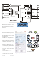
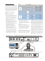
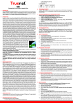
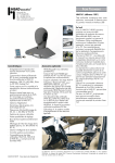
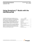
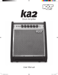
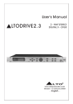
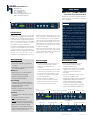
HEAD acoustics GmbH DATA SHEET MFE VI.1 (Code 6462) Ebertstraße 30a D-52134 Herzogenrath Tel: +49 (0)2407-577-0 Fax: +49 (0)2407-577-99 E-mail: [email protected] WEB: www.head-acoustics.de Telecom Measurement Front End Portable two-channel front end with integrated mouth amplifier and software-controlled level adjustment Overview The portable, cost-effective front end MFE VI.1 forms the connecting link between data acquisition via the artificial head HMS II.3 and digital speech quality analysis with ACQUA. Connected to a notebook or PC via the Plug&Play USB port, it is configured and controlled by ACQUA. Via MFE VI.1, ACQUA performs automated measurements according to international, HEAD acoustics or user-defined standards. MFE VI.1 thus serves for problem solving, quality control, benchmarking and product optimization in many areas where the voice quality of communication devices and networks plays an important role. The integrated power amplifier allows direct connection to the artificial mouth of HMS II.3. In addition, MFE VI.1 can be extended to a digital binaural equalizer (by software option). DESCRIPTION MFE VI.1 is a universal two-channel front end for measuring digital and analog (tele)communication components and networks. The battery power supply and the compact, light-weight design enable the use of MFE VI.1 as a portable system for data acquisition and signal conditioning. Due to the integrated digital echo path filter, it is particularly suited for the measurement of echo cancellers. The programmable digital signal processor (DSP) also allows the use of user-defined filters and, in combination with the BEQ option, the equa- MAIN FEATURES DSP onboard • Signal processing/filtering/equalization in real time • Digital filters, e.g. for echo path simulation or as user-defined filters Mobile use • Battery power, min. 2 h operating time • Compact design (hand luggage) • USB port: no PCI slots required • Can be used with notebook User-friendly • Integrated power amplifier allows direct connection of artifical mouth during mains operation/external power supply • Plug&Play operation • Control via intuitive Windows® software environment (ACQUA) Universal • Synchronizable in- and outputs, full duplex capabilities • IN: 2x Balanced, 2x Line, 2x MIC, 2x Pulse, AES/EBU, USB 2.0 • OUT: 2x Balanced, 2x Line, 2x Pulse, 2x Speaker, Headphones, AES/EBU, USB 2.0 • Binaural equalizer (software option) • High dynamic range, 24 bit technology • On-line switching of external and internal supply, "smart charge" electronics lization of artificial head signals, all in real time. Via Pulse in- and outputs (TTL levels) the measured devices can be controlled. The USB port allows Plug&Play operation with any standard Windows® PC or notebook. MFE VI.1 is controlled by an intuitive user interface via the communication analysis software ACQUA. When measuring especially low or high input levels, the level of the analog inputs can be adjusted by software control in 10 dB steps from -40 to +20 dB. APPLICATIONS DEPLOYMENT AREAS • Electrical / electroacoustical binaural measurements of analog / digital (tele)communication devices / networks • Particularly suited for measurement and control of echo cancellers (in real time) • Use of non-linear echo paths, e.g. for simulation of loudspeaker distortions or housing vibrations • Mouth amplifier for HMS II.3 • Binaural equalizer (software option) • Mobile data acquisition and analysis • Direct impedance measurements • Research and development: signal processing development, design validation, design ranking • Manufacturing: production control with regard to voice quality, ensuring system performance and compliance to standards • Providers and carriers: speech quality monitoring, troubleshooting • Independent test labs: objective comparison of products from different manufacturers, custom-ordered speech quality tests • Sales and marketing: demonstrating excellent quality of products tested and optimized with ACQUA and MFE VI.1 Front: 2x Microphone In Display 2x Line In/Out 2x Balanced In/Out 600 Ohm Rear: DC In/Out AES EBU In/Out USB LS Status LED Pulse 08.13 D6462e5 Operating Diode Speaker Headphones Subject to change Pulse in 1+2 (L+R) Pulse out 1+2 (L+R) AES / EBU in 1(L) Speaker 1+2 (L+R) D/A Mic in 1(L) -40 dB -30 dB -20 dB -10 dB 0 dB +10 dB +20 dB Line in 1(L) Balanced in 1(L) Mic in 2(R) Line in 2(R) 0 dB +10 dB A/D A/D Line out 1(L) AES / EBU out 1+2 (L+R) DSP Headphones (L+R) D/A Balanced in 2(R) Line out 2(R) 0 dB +10 dB AES / EBU in 2(R) MFE VI.1 Balanced out 1(L) Balanced out 2(R) USB in/out CONNECTION POSSIBILITIES MFE VI.1 has been developed for a wide range of applications and therefore offers numerous connection possibilities. The block diagram above gives a comprehensive overview. DIGITAL ECHO PATH Due to the integrated digital echo path the frontend MFE VI.1 is particularly suited for real-time measurement of echo cancellers. The pictures to the right show the function of the digital echo path which may consist of up to two branches: • In addition to the assignment of the inand output of the echo path, a source signal can be added. • Eight different filters according to ITU-T Recommendation G.168 can be selected, each with two amplitude factors, i.e. 16 filters in total. An Echo Return Loss (ERL) value is automatically assigned to each filter which can be modified by the user. The default ERL values are also derived from ITU-T G.168. Moreover, a userdefined filter can be used (for sampling rates of 8, 16, 48 kHz). • Non-linear distortions (NLD) can be used in the echo path, e.g. for simulation of loudspeaker distortions or housing vibrations. • Gain and noise level can be set. • Up to three parallel delay lines with a maximum delay of 900 ms can be defined. For each delay line an attenuation value can be determined. 08.13 D6462e5 MFE Input ACQUA Subject to change First Branch Second Branch Filter Filter ERL ERL Add Source NLD NLD Gain Noise + + t1 t2 t3 t1 t2 t3 Att1 Att2 Att3 Att1 Att2 Att3 + MFE Output Echo path block diagram Echo path settings in ACQUA Gain Noise SOFTWARE OPTION BEQ By an optional software upgrade, MFE VI.1 can be extended to a binaural equalizer. For this purpose, individual equalization filters for use with the corresponding artificial head are determined by HEAD acoustics and stored in the front end. These filters are then available in ACQUA for the following equalization types: • User: user-defined equalization • Lin: Linear (no equalization) • FF - Free field equalization In this case artificial head microphone signals for frontal sound incidence in a reflection-free environment are equalized so that a linear frequency-independent transfer response is obtained. • ID - Independent of Direction The outer ear transfer function can be sub-divided into two components. One is dependent on direction, the other is independent of direction. The directionally dependent one is affected by the diffraction and reflection resulting from external human geometry including the chest region, shoulder, head, edge of outer ear, cavum conchae opening. The independent-of-direction components result from resonances in the cavum conchae hollow and the ear canal entrance. ID equalization linearizes only those components of the transfer function produced by the independent of direction components. This indepen- dent of direction component of the outer ear function cannot be determined by measuring techniques. It is the result of a purely mathematical calculation. • DF - Diffuse field equalization In this case the artificial head recording microphone is brought into a diffuse sound field and in turn equalized so that a linear frequency-independent transfer function can be measured. The calibration values of the artificial head microphones are automatically read out from MFE VI.1 by ACQUA and are transferred for both channels into the list of calibration values in the window "Calibration Values". This window is evoked via the corresponding command in the ACQUA settings menu. In the rows "Acoustic" and "Electric" of the window "Calibration Assignment" (also evoked via the ACQUA settings menu), the microphones which are used for reference measurements and measurements are subsequently selected. The measurement descriptors which use one of these calibrations (SMD parameter "Calibration & unit") automatically use the values of the microphones selected in the Calibration Assignment. In the ACQUA software module for control of MFE VI.1 the desired type of equalization is selected via a context menu, which opens by right-clicking one of the input blocks. CONNECTING MFE VI.1 TO COMMUNICATION ANALYSIS SYSTEM ACQUA AND TO ARTIFICIAL HEAD HMS II.3 DC In 12V DC Out 12V AES In AES Out Pulse GmbH Speaker Headphones AES Shield to Chassis Out OFF In USB MFE VI.1 back panel Speaker USB MIC R MFE VI.1 front panel Left Right (I) (II) 200V Polarisation Voltage Out Bal. In Line Out ON LCD Modul 2 x 16 Mic 0V In OFF MODE Left (I) L (I) R (II) L (I) Right (II) Left (I) Right (II) Power R (II) 08.13 D6462e5 6462 MFE VI.1 Subject to change STANDARD DELIVERY ITEMS Technical data – MFE VI.1 Overview Interfaces Input: MIC In: Balanced In: Line In: Pulse In: AES EBU In: USB In/Out: Output: Balanced Out: Line Out: AES EBU Out: Power Amplifier “Speaker”: Headphones: Pulse Out: Channel separation: Digital unit Signal processor: A/D converter: Sampling rate: For all terminated inputs: THD+N > 95 dB (1 kHz ) and nominal level (-6 dBFS), channel separation > 60 dB, amplification for each channel adjustable in 10 dB steps from -40 to +20 dB (nominal sensitivity 0 dBV), frequency range 20 Hz – 20 kHz ± 0.3 dB, selectable filters: highpass 1st order 180 Hz (±10%) passive, highpass 3rd order 22 Hz active 2 x at front, nominal sensitivity in normal mode 114 dBSPL: 12.5 mVeff/Pa (calibratable), microphone voltage feed 120 V and 200 V 2 x at front, symmetrical, 600 Ohm input impedance, nominal sensitivity 1 Veff at 0 dB gain, maximum input signal voltage approx. 9 Veff 2 x at front, BNC, asymmetrical, nominal sensitivity 1 Veff at 0 dB gain, input impedance 50 kOhm, maximum input signal voltage approx. 9 Veff 2 x at rear via D-Sub socket, limit frequency approx. 20 kHz, input sensitivity TTL level 1 x at rear, XLR, digital audio input 1 x at rear, universal serial bus 2.0 for control and data exchange with ACQUA For all outputs (except “Speaker”): THD + N > 90 dB (1 kHz), frequency range 20 Hz – 20 kHz ± 0.3 dB 2 x at front, symmetrical, 600 Ohm output impedance, nominal level 1 Veff for all sensitivities, max. level approx. 6V 2 x at front, BNC, nominal level 1 Veff for all sensitivities, output impedance approx. 10 Ohm, max. level approx. 6V; direct impedance measurement (approx. 4 – 350 Ohm) possible at Line Out 1 1 x at rear, XLR, digital audio output Bridge amplifier with max. 14 W sine output power at 4 Ohm at 0.1% distortion factor, signal-to-noise ratio 73 dB, requires external power supply via power unit PSH I.1 1x rear panel, 6.3 mm cinch socket, headphone type: dynamic, nominal level approx. -12dBV/ 250mV (at +10 dB output adjustment correspondingly higher), not calibratable, maximum current: approx. 30mA, headphones with low impedance (<50Ohm) can lead to distortions during high levels 2 x at rear via D-Sub socket, TTL level Typically > 90 dB (without equalization) Motorola DSP56311 (120 Mips), 24 bit data processing 24 bit resolution Internal synchronization 32 kHz, 44.1 kHz, 48 kHz; alternatively: external synchronization via AES/EBU with 32 kHz, 44.1 kHz, 48 kHz Digital echo path filter Linear (Lin), Independent-of-direction (ID), Free-field (FF), Diffuse-field (DF), User-specific (USER) Filter: Digital equalizations (requires BEQ option): Power supply On-line switching between external and internal supply, “smart charge“ electronics External power unit - PSH I.1 Input voltage: 100-240 V AC ~ 47-63 Hz Max. input current: 0.65 A at 90 V AC Output voltage: 15 V DC Output current: 4A DC output: XLR 4-pin External DC power supply: 15 V DC nominal voltage (9 V - 18 V, e.g. vehicle circuit or external power unit PSH I.1) Internal DC power supply: NiMH rechargeable battery, 12 V, 2 Ah Charging procedure: Fast charge (max. 3 h), conservation charge Operating time with battery: Minimum 2 h Current, power consumption: Charging and operating (during power amplifier mode): 4 A / 60 W Operation: Remote control: Via ACQUA software (Version 2.5.100 or later) System check: Automatic hardware check of digital and analog units as well as A/D converter at system boot Display: 2 x 16-digit LCD with LED background lighting for display of active in/outputs and sensitivities on both channels Environmental conditions Operating temperature 0°C - 45°C, 32°F - 113°F range: (in power amplifier mode: 0°C - 35°C, 32°F - 95°F) Storage temperature range: -20°C - 70°C, -4°F - -94°F Air Humidity: 35 – 70 % (non-condensatory environment) Housing Overall dimensions (WxHxD): 327 mm x 44 mm x 230 mm Weight: ca. 2.5 kg 08.13 D6462e5 Subject to change • MFE VI.1 (Code 6462): Two-channel analog/digital frontend (incl. USB cable, 1.5m) • PSH I.1 (Code 1364): External power supply, 100-240 V AC -> 15 V DC • PCC I.9x (Code 997x): Mains cable to local specification • Pulse Breakout Cable: D-Sub 9-pin « 4 × BNC • User Manual ACCESSORIES • ACQUA (Code 6810)*: Advanced Communication Quality Analysis System • ACQUA Compact Systems (Code 68xx)* • HMS II.3-33/HMS II.3-34 (Code 1230.1/1230.2): Head and torso simulator including ear simulator and artificial mouth • CTD II (Code 6078): Cable Telecom plug « D-Sub 9-pin (for GSM/3G) alternatively: CTD III (Code 6081): Cable Telecom plug « D-Sub 9-pin (for CDMA) OPTIONS • Software Option MFEVI.1-BEQ (Code 6461): extends MFE VI.1 to Binaural Equalizer *ACQUA Version 2.5.100 or later required! represented by