1
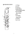
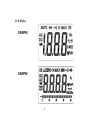
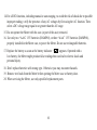
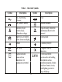
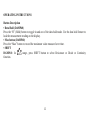
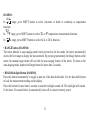
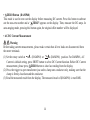
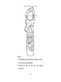
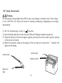
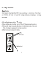
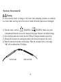
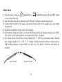
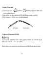
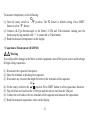
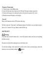
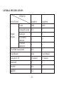
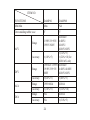
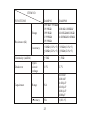
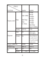
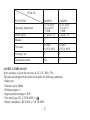
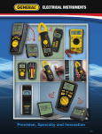
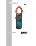
99 Washington Street
Melrose, MA 02176
Phone 781-665-1400
Toll Free 1-800-517-8431
Visit us at www.TestEquipmentDepot.com
DAMP60/DAMP68
USER’S MANUAL
DAMP60 AUTO RANGING AMP CLAMP METER/
DAMP68 AUTO RANGING TRUE RMS AMP CLAMP METER
TABLE OF CONTENTS
TITLE
FEATURES.........................................................................................
FUNCTIONS DESCRIPTION............................................................
SAFETY INFORMATION.................................................................
OPERATING INSTRUCTIONS........................................................
MAINTENANCE................................................................................
SPECIFICATIONS..............................................................................
SAFETY COMPLIANCE....................................................................
2
PAGE
3
4-6
7-11
12-22
22
23-27
27
FEATURES
DAMP60
• Ergonomic Design
• Rugged Over-mold Housing
• Easy to use
• Data Hold, Max Hold
• Auto Ranging
• 3-1/2 Digit Jumbo LCD Display
• Continuity Buzzer, Diode Test
• Auto Power Off
• Includes Carrying Case & Test Leads
DAMP68
• Ergonomic Design
• Rugged Over-mold Housing
• Ideal for HVAC/R Applications
• True RMS
• Analog Bar Graph
• Easy to use
• Temperature
• Capacitance
• Range, Zero Button
• Auto Ranging
• 3-3/4 Digit Jumbo LCD Display
• Continuity Buzzer, Diode Test
• Auto Power Off
• Includes Carrying Case & Test Leads
& K-Type Thermocouple
3
FUNCTION DESCRIPTION
These clamp meters have been designed for industrial use. They are high performance
instruments offering a wide variety of measurements. Their over-mold housing as well
as their ergonomic design makes them indispensable, durable and rugged for almost
any situation or application.
DAMP60 is a 3-1/2 digit auto ranging digital display clamp meter. It measures DC/ACV;
AC Current; Resistance; Diode Test; Continuity Buzzer and Frequency.
DAMP68 is a 3-3/4 digit auto/manual ranging digital display clamp meter with true RMS
measurement. It measures true RMS AC/DC Voltage, Current, Resistance, Capacitance
Frequency, Diode Test, Continuity Buzzer and Temperature Measurement.
4
● INSTRUMENTS OVERVIEW
1. LCD Display
2. Clamp Jaw
3. Function Switch
4. Backlight (DAMP60)
Data Hold /Backlight (DAMP68)
5. Max Hold (DAMP60)
ZERO (DAMP68)
6.SHIFT
7.Hold (DAMP60)
Range (DAMP68)
8. Jaw Release
9. Input Terminal
2
3
8
5
6
1
7
4
9
5
LCD Display
DAMP60
DAMP68
6
SAFETY INFORMATION
To avoid possible electric shock or personal injury, follow these guidelines:
◆Do not perform the performance tests or adjustment procedures described in this manual unless
you are qualified to do so.
◆The information provided in this manual is for the use of qualified personnel only.
◆Read “Safety Information” before using this meter.
◆These multimeters are battery operated, with a digital display.
◆These Meters comply with IEC61010-1,2001 CAT Ⅲ 600V. Refer to “GENERAL
SPECIFICATIONS” for more information.
◆In this manual, a Warning identifies conditions and actions that pose hazards to the user.
◆A Caution identifies conditions and actions that may damage the Meter or the equipment under test.
International symbols used on the Meter and in this manual are explained in Table 1 on page 11.
7
Warning
To avoid possible electric shock or personal injury, and to avoid possible damage to the Meter
or to the equipment under test, comply with the following practices:
1. Do not use the Meter in a manner not specified by this manual or the safety features
of the Meter may be impaired.
2. Before using the Meter, inspect the case. Do not use the Meter if it is damaged.
Look for cracks or missing plastic. Pay particular attention to the insulation
around the connectors.
3.
Inspect the test leads for damaged insulation or exposed metal. Check
the test leads for continuity. Replace damaged test leads before using the Meter.
4. Verify a Meter’s operation by measuring a known voltage. Do not use the Meter if it operates
abnormally. Protection may be impaired. When in doubt, have the Meter serviced.
5.
Do not apply more than the rated voltage, as marked on the Meter,
between the terminals or between any terminal and earth ground.
6.
Do not measure voltages above 600 V in Category III installations.
8
7.
Do not measure voltage when the function/range switch is set on the
resistance (ohms), current, capacitance or temperature settings. Never measure current when the
meter is set on the resistance (ohms), capacitance or temperature settings. Never measure AC
voltage when the meter is set on DC voltage or DC current settings. Setting the meter on the
incorrect function may burn out some of the internal circuitry and may pose a safety hazard.
8. Use caution when working with voltages above 30 V AC rms, 42 V AC peak, or 60 V DC.
These voltages pose a shock hazard.
9. Use the proper terminals, function, and range for all measurements.
10.
Do not operate the Meter around explosive gas, vapor, or dust.
11.
When using the probes, keep the fingers behind the finger guards.
Do not touch the metal probes of the test leads when making a measurement.
12. When making connections, connect the common test lead before connecting the
live test lead; when disconnecting, disconnect the live test lead before
disconnecting the common test lead.
13. Disconnect circuit power and discharge all high-voltage capacitors before testing
resistance, continuity, diodes, or capacitance.
9
14. For all DC functions, including manual or auto-ranging, to avoid the risk of shock due to possible
improper reading, verify the presence of any AC voltages by first using the AC function. Then
select a DC voltage range equal to or greater than the AC range.
15. Do not operate the Meter with the case (or part of the case) removed.
16.. Use only two “AAA” 1.5V batteries (DAMP60), or three “AAA” 1.5V batteries (DAMP68),
properly installed in the Meter case, to power the Meter. Do not use rechargeable batteries.
” appears. Operated with a
17. Replace the battery as soon as the battery indicator “
low battery, the Meter might produce false readings that can lead to electric shock and
personal injury.
18. Don’t replace batteries with wrong type. Otherwise you may encounter hazards.
19. Remove test leads from the Meter before opening the Meter case or battery door.
20. When servicing the Meter, use only specified replacement parts.
10
Table 1.Electrical Symbols
Symbol
Description
Symbol
Description
AC (Alternating
Current)
DC (Direct Current)
Fuse
Caution, risk of
electric shock.
Hazardous voltage.
Battery (Low battery)
when shown on display
Diode
Risk of danger. Important
Information. Refer to the
manual.
Earth ground
AC or DC
Complies with EU
directives
For measurements
performed in the building
installation such as
distribution panels, feeders
and short branch circuits,
and lighting systems in
large buildings.
Double Insulated
Continuity/Beeper
Application and
removal from
hazardous live
conductors permitted
CAT III
11
OPERATING INSTRUCTIONS
Button Description
• Data Hold (DAMP60)
Press the “H” (Hold) button to toggle in and out of the data hold mode. Use the data hold feature to
lock the measurement reading on the display.
• Max button (DAMP60)
Press the “Max” button to record the maximum value measured over time.
• SHIFT
DAMP60: In Ω range, press SHIFT button to select Resistance or Diode or Continuity
function.
12
DAMP68:
Ω/
In / range, press SHIFT button to select resistance or diode or continuity or capacitance
function.
°C
In °F range, press SHIFT button to select °C or °F temperature measurement function.
/
In
A range, press SHIFT button to select ACA or DCA function.
• RANGE button (DAMP68)
The meter defaults to auto-ranging mode when powered on. In this mode, the meter automatically
selects the best range to display the measurement. By pressing momentarily the Range button on the
meter, the manual range mode will override the auto-ranging feature of the meter. To return to the
auto-ranging mode, depress the Range button for more than 2 seconds.
• HOLD/Backlight Button (DAMP68)
Press this button momentarily to toggle in and out of the data hold mode. Use the data hold feature
to lock the measurement reading on the display.
Press this button for more than 2 seconds to turn the backlight on and off. The backlight will remain
lit for about 10 seconds before it automatically turns off to conserve battery power.
13
• ZERO Button (DAMP68)
This mode is used to zero out the display before measuring DC current. Press this button to subtract
out the non-zero number and a “ ZERO” appears on the display. Then, measure the DC amps. In
auto-ranging mode, pressing this button again, the original offset number will be displayed.
• AC/DC Current Measurement
Warning
Before taking current measurements, please make certain that all test leads are disconnected from
the meter terminals.
A (DAMP60) or
A (DAMP68) position. For DAMP68, AC
(1) Set the rotary switch at
Current is default setting, press SHIFT button to select DC Current function. Before DC Current
measurement, please press ZERO button to clear last reading from the display.
(2) Press the trigger to open transformer jaw and to clamp one conductor only, making sure that the
clamp is firmly closed around the conductor.
(3) Read the measured result from the display. The measured result of (DAMP68) is true RMS.
14
Notes:
• Clamp the jaw around one conductor only;
• Close the jaw completely;
• Center the wire in the jaw for highest
accuracy.
15
• DC Voltage Measurement
Warning
Do not measure voltage higher than 600V. It may cause damage to internal circuit. If the voltage
is over 1000 VDC, the beeper will sound for warning continuously, designating an over-range
measurement.
V position.
(1) Set the function/range switch to
(2) Insert the black and red test leads into the COM and V/Ω input terminals respectively.
(3) Touch the black test lead to the negative polarity, and touch the red test lead to positive polarity
of the circuit to be tested.
(4) Read the measured voltage on the display. If the test leads are reversed, the “-” indicator will
appear on the display.
red test lead
red test lead
black test lead
black test
lead
16
• AC Voltage Measurement
Warning
Do not measure voltage higher than 600V. It may cause damage to internal circuit. If the voltage is
over 750 VAC, the beeper will sound for warning continuously, designating an over-range
measurement.
V position.
(1)) Set the function/range switch to
(2) Insert the black and red test leads into the COM and V/Ω input terminals respectively.
(3) Measure the voltage by touching the probes to the desired test points of the circuit.
With AC voltage, the polarity of the test lead is not a factor.
(4) Read the measured voltage on the display.
red test lead
black test lead
17
• Resistance Measurement (Ω)
Warning
To avoid electrical shock or damage to the meter when measuring resistance or continuity
in a circuit, make sure the power to the circuit is turned off and all capacitors are discharged.
Ω/
(DAMP68). Make sure power
(1) Turn the rotary switch to Ω (DAMP60) or /
is disconnected from the circuit to be measured. Resistance function is the default setting.
(2) Insert the black and red test leads into the COM and V/Ω input terminals respectively.
(3) Measure the resistance by touching the probes to the desired test points of the circuit.
(4) Read the measured resistance on the display. When the resistance value is over range,
“OL” will be indicated on LCD display.
red test lead
black test lead
18
• Diode Check
Ω/
(1) Turn the rotary switch to Ω (DAMP60) or / (DAMP68) position. Press SHIFT button
to select diode function.
(2) Insert the black and red test leads into the COM and V/Ω input terminals respectively.
(3) Connect the red probe to the anode side and the black probe to the cathode side of the diode
being tested.
(4) Read the forward bias voltage value on the display.
(5) If the polarity of the test leads is reversed with diode polarity, the display reading shows “OL”.
This can be used to distinguish the anode and cathode sides of a diode.
(6) For silicon diodes, forward bias voltage should be 0.5~0.8V, for germanium diodes, forward
bias voltage should be 0.2~0.3V. “0 V” reading in both directions indicates a shorted diode,
“OL” reading indicates an open diode. In either case, the diode is defective and should be
replaced.
red test lead
black test lead
19
• Continuity Measurement
Ω/
/ (DAMP68) position. Press SHIFT button
(1) Turn the rotary switch to Ω (DAMP60) or
to select continuity function.
(2) Insert the black and red test leads into the COM and V/Ω input terminals respectively.
(3) If the resistance is ≤ 50 Ω, the beeper will sound continuously.
red test lead
black test lead
• Temperature Measurement (DAMP68)
Warning
To avoid possible damage to the Meter or other equipment, remember that the included K-Type
thermocouple is rated -40° to 752°F (-40° to 400°C).
When the Meter is not connected to the included thermocouple, OL will be shown on the display.
20
To measure temperature, do the following:
°C
(1) Turn the rotary switch to
°F position. The °C feature is default setting. Press SHIFT
button to select °F feature.
(2) Connect a K-Type thermocouple to the Meter’s COM and V/Ω terminals, making sure the
thermocouple plug marked with “+” is connected to V/Ω terminal.
(3) Read the measured temperature on the display.
/
• Capacitance Measurement (DAMP68)
Warning
To avoid possible damage to the Meter or other equipment, turn off the power source and discharge
all high-voltage capacitors.
(1) Disconnect the capacitor from power.
(2) Short the terminals to discharge the capacitor.
(3) Disconnect any resistors that might be between the terminals of the capacitor.
Ω/
(4) Set the rotary switch to the / position. Press SHIFT button to select capacitance function.
(5) Plug the black test lead into the COM port and the red test lead into the V/Ω port.
(6) Connect the test leads to the two terminals of the capacitor and measure the capacitance.
(7) Read the measured capacitance value on the display.
21
• Frequency Measurement
(1) Turn the rotary switch to Hz position.
(2) Insert the black and red test leads into the COM and V/Ω input terminals respectively.
(3) Measure the frequency by touching the probes to the desired test points of the circuit.
(4) Read the measured frequency on the display.
• Turn off
Please set the function switch to OFF position after using.
The Meter enters the “Sleep mode” and blanks the display if the Meter is not used and the input is
inactive for 15 minutes. Press any button to wake the Meter up.
MAINTENANCE
Warning
If the Meter fails, check the batteries first,review this manual to make sure that you are operating
the Meter correctly.
Disconnect test leads before opening the case or the battery door.
To avoid false readings, which could lead to possible electric shock or personal injury, replace the
” appears.
batteries as soon as the battery indicator “
22
GENERAL SPECIFICATIONS
ITEM NO.
FUNCTIONS
Count
DAMP60
2000
DAMP68
4000
Analog Bar graph
NA
Y
Backlight
Low battery
indicator
Overload
indication
True RMS measurement
Y
Y
Y
Y
Y
Y
NA
Y
Digital
Display
Auto/Manual
Auto
Auto/Manual
Auto power off
15 minutes
15 minutes
Data hold
Y
Y
RANGE
NA
Y
ZERO
NA
Y
23
ITEM NO.
FUNCTIONS
Min/Max
DAMP60
Max
Over-molding rubber case
Y
Accuracy
Y
400.0mV/
1.999V/19.99V/ 4.000V/
199.9V/600V
40.00V/
400.0V/600V
±(1.0%+5)
±(1.0%+5)
±(2.0%+10) for
400.0 mV only
199.9mV/1.999V/ 400.0mV/
19.99V/199.9V/ 4.000V/40.00V/
600V
400.0V/600V
±(0.8%+5)
±(0.8%+5)
Range
Accuracy
Range
199.9/600A
±(3.0%+5)
NA
400.0A
±(3.0%+10)
400.0A
Accuracy
NA
±(3.0%+5)
Range
ACV
Accuracy
DCV
ACA
DCA
DAMP68
NA
Range
24
ITEM NO.
FUNCTIONS
Range
Resistance (Ω)
Accuracy
Continuity (audible)
Diode test
Capacitance
Open
circuit
voltage
DAMP60
199.9Ω/1.999KΩ/
19.99KΩ/
199.9KΩ/
1.999MΩ/
19.99MΩ
DAMP68
400.0Ω/4.000KΩ/
40.00KΩ/400.0KΩ/
4.000MΩ/40.00MΩ
<1MΩ±(1.0%+5) <1MΩ±(1.0%+5)
≥1MΩ±(2.0%+5) ≥1MΩ±(2.0%+5)
≤ 50Ω
≤ 50Ω
1.5V
2.7V
Range
NA
Accuracy
NA
25
40.00nF/
400.0nF/
4.000µF/
40.00µF/
400.0µF/
4000µF
±(4%+5)
ITEM NO.
FUNCTIONS
DAMP60
10Hz~1999Hz
Frequency counter
Temperature
Range
Input Voltage
range:
0.2~30Vrms
Accuracy
±(3%+10)
Range
NA
Accuracy
NA
Frequency response (Hz)
Withstand Voltage
Type
Jaw
Opening
50/60Hz
6000V AC
Coil
≥ 1.1" (28mm)
26
DAMP68
99.99Hz/
999.9Hz/
9.999KHz/
99.99KHz/
999.9KHz/
9.999MHz
Input Voltage
range: 0.2~600Vrms
±2.0%
-40° to 752°F
(-40° to 400°C)
-40° to 4°F ±(8%+8)
4° to 32°F ±(1.2%+7)
32° to 212°F ±(1.2%+6)
≥212°F ±(3%+5)
50/60Hz
6000V AC
Hall
≥ 1.2" (31mm)
ITEM NO.
FUNCTIONS
Carrying Case
DAMP60
32° to 104°F
(0° to 40°C)
≤ 75RH
2 –AAA 1.5V
Y
20AWG
CAT Ⅲ 600V
Y
DAMP68
32° to 104°F
(0° to 40°C)
≤ 75RH
3-AAA 1.5V
Y
20AWG
CAT Ⅲ 600V
Y
Temperature probe
NA
Y
Operating Temperature
Power source
Manual
Test Lead
SAFETY COMPLIANCE
Note: Accuracy is given for one year, at 23°±3°C, RH ≤ 70%.
This unit was designed to be safe at least under the following conditions:
• Indoor use
• Altitude: up to 2000m
• Pollution degree: 2
• Ingress protection degree: IP20
• Test leads type: CE, CAT III 600V,1A
• Safety Compliance: IEC61010-1, CAT III 600V
27
99 Washington Street
Melrose, MA 02176
Phone 781-665-1400
Toll Free 1-800-517-8431
Visit us at www.TestEquipmentDepot.com
DAMP60/DAMP68 User’s Manual
Specifications subject to change without notice
©2009 GENERAL TOOLS & INSTRUMENTS™
NOTICE - WE ARE NOT RESPONSIBLE
FOR TYPOGRAPHICAL ERRORS.
MAN#DAMP60/DAMP68 7/09