1
INTRODUZIONE
1.1
Dominio
UTM project e' un modulo di UUTM&M.
UUTM&M e' una suit di servizi aziendali con lo scopo di Monitorare e controllare i dispositivi elettrici usati da una compagnia.
La forza di UTM e; nell'avere un singolo punto di controllo, dove e' possibile eseguire IT operazioni e monitorare costi energetici in modo da aumentare i risparmi.
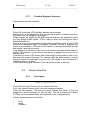
UTM si concentra sopratutto su dispositivi CISCO che implementano il protocollo POE. esempi
sono: IP Phones, access point, web cam e in un futuro anche luci e altri dispositivi IP.
UTM mette a disposizioni strumenti di controllo in grado di: capire e controllare i bisogni di corrente di dispositivi elettrici. I dispositivi in grado di essere riconosciuti sono tutti quelli che implementano il nuovo protocollo della Cisco: EnergyWise.
In piu' UTM provvede anche una vasta gamma di features usate per estendere i servizi degli IP
Phone services tra cui:
•
Click to dial
•
Text message
•
Presences
I servizi di UTM sono utilizzabili in due modi diversi: localmente da un amministratore o da remoto dai dipendenti aziendali attraverso l'intranet.
UTM e' in grado di collezionare in un unico punto di controllo tutti i dispositivi utilizzati in una
network aziendali.
Quindi siamo in grado con poche operazione di applicare politiche di scheduling e di controllo
globali.
In piu' grazie allo scheduler quando un dispositivo non e' utilizzato viene spento automaticamente.
Questo porterà' un sostanziale rientro economico.
1.2
Metodologie
L'intero progetto e' stato sviluppato seguendo le linee guida dell'ingegneria del software.
E quindi ogni diversa fase produttiva e' stata ben rispettata e ben documentata.
Questo ci ha permesso di sviluppare UTM in maniera piu' semplice ma allo stesso tempo potente. Chi verrà dopo di noi si troverà molto materiale disponibile, che lo aiuterà a mantenere il
progetto e ampliarle le sue funzionalità.
Come standard di grafica e' stato scelto UML o Unified Modelling Language, in quanto ritenuto
il piu' opportuno e largamente utilizzato.
1.3
Tecnologie
La forza principale del progetto si basa su due protocolli SNMP e AXL fondamentali per il corretto funzionamento.
SNMP or Simple Network Management Protocol appartiene alla suite di protocolli Internet definita dalla IETF (Internet Engineering Task Force).
Esso e ci permette di ricavare informazioni sugli apparati di una network aziendale. Informazioni quali:
•
•
•
tipo di dispositivi attaccati
nome
energia consumata.
Le specifiche di queste informazioni sono puntualizzate da un protocollo della Cisco: EnergyWise.
AXL o Administrative XML e' sostanzialmente un'interfaccia accessibile tramite richieste http e
xml. Questa interfaccia risiede dentro il Call Manager della Cisco.
AXL e' stata implementata da UTM in modo tale da ricavare informazioni sugli IP Phone, quali:
•
Proprietario
•
Modello
•
numero di telefono
•
credenziali.
1.4
Struttura della tesi
La tesi e' costituita essenzialmente da tre parti:
la prima parte e' quella introduttiva in cui viene spiegato il progetto e i motivi che ci hanno portato alla sua realizzazione.
Viene inoltre riportato come il progetto e' stato svolto, metodologie usate e la sua evoluzione
nel tempo.
La parte centrale e' costituita dalle ―features‖ del sistema, ossia operazioni e strumenti messi a
disposizione agli utenti, i quali andranno ad utilizzare il prodotto.
Per ogni feature viene esposto: una breve descrizione, I bisogni funzionali e la lista degli input
in ingresso accettati.
la parte finale riguarda i requirement usati dall'applicazione e quelli richiesti all'utente in modo
da poter utilizzare al meglio il software e trarne il massimo benefecio.
INTRODUCTION
1.5
Purpose
The UTM project is a module of UUTM&M or Unified User Device Management & Monitoring.
UUTM&M is a suite made up of services with the aim of monitoring and managing consumption
by devices used by a company.
UTM is single point of control with the aim of allowing IT operations and facilities to measure
and fine-tune power usage to realize significant cost savings. UTM focuses on reducing power
utilization in all devices connected to a Cisco network, ranging from Power over Ethernet (POE)
devices such as IP phones and wireless access points to integration with IP-enabled building
and lighting controllers.
It uses an intelligent network-based approach, allowing IT and building facilities management to
understand, optimize, and control power across an entire corporate infrastructure, potentially affecting any powered device by using Cisco's new management protocol ―EnergyWise‖.
Moreover UTM provides a suite of services used in order to extend the IP Phone features.
Services like:
•
Click to dial
•
Text message
•
Presences
•
…
In addition UTM is interfaced with the company's Intranet in order to extend its services to all
the employees.
UTM is able of collecting and showing network devices in one point of control.
With few operations you can set global policy and apply global controls.
Moreover the scheduler knows if devices are not consuming energy, if so it is automatically
turned off.
This will give back an interesting return.
1.6
Methodologies
The all project was developed by following the software engineering guidelines.
Each process phases was respected and well documented.
Thanks to this UTM was easy created but has been became powerful.
Moreover who will come after us will find many documents which will help him to maintain the
project and extends its functionality easily.
UML or Unified Modelling Language has been chosen since It is well documented and widely
used.
1.7
Technology
UTM strengths come from two important protocols: SNMP and AXL.
SNMP or Simple Network Management Protocol is a component of the Internet Protocol Suite
as defined by the Internet Engineering Task Force (IETF).
Thank to SNMP we are capable of retrieving network devices information. e.g:
•
model type
•
•
name
energy consumption
Where and how make SNMP are specified by Cisco EnergyWise protocol.
AXL or Administrative XML is an interface. You can access to it by HTTP and XML request.
This interface is within the Cisco Call Manager.
AXL is implemented by UTM in order to retrieve IP Phone information like:
•
IP Phone owner
•
Models
•
Numbers
•
credential
1.8
Thesis structure
This thesis is made up by three part:
the first part is an introduction. it explains what UTM is and what are its aims behind its creation.
Moreover it says how UTM was developed, the Methodologies used and how it is changed over
the time.
The main part is made up by UTM features.
Each feature is made up by three part: brief description, functional requirements and Stimulus/Response sequences.
The last part concerns about system and user requirements.
]
Mom & Dad,
Where there's a will, there's a way.
Table of Contents
1
1 Introduction ....................................................................................... 7
1.1 Purpose .................................................................................................... 7
1.2 Document Conventions ............................................................................. 7
8 1.3 Intended Audience and Reading Suggestions ......................................... 8
8 1.4 Test Step and workbench ........................................................................ 8
10 1.5
Project Scope ..................................................................................... 10
10 1.6
Organization ....................................................................................... 10
11 1.7
Communication .................................................................................... 11
12 1.8
Worked Hours..................................................................................... 12
2 13 2 Overall Description ..................................................................... 13
13 2.1 Product Perspective ............................................................................ 13
15 2.2 Product Features ................................................................................. 15
16 2.3 User Classes and Characteristics ........................................................ 16
17 2.4 Operating Environment ........................................................................ 17
19 2.5 Assumptions, Dependencies and Constraints ..................................... 19
3 21 3
Configuration Management ....................................................... 21
21 3.1
Reference Documents ........................................................................ 21
21 3.2
Responsibility ..................................................................................... 21
21 3.3
Component, Tools and Products Used .............................................. 21
22 3.4
Activity Plan ........................................................................................ 22
23 3.5 Gant diagram ....................................................................................... 23
24 3.6 Project risks ......................................................................................... 24
25 3.7
Deliverables ........................................................................................ 25
4 26 4
System Features ........................................................................ 26
26 4.1
SNMP ................................................................................................. 26
26 4.1.1 Description ................................................................................................. ..... 26
34 4.1.2 Functional Requirements ........................................................................... ..... 34
37 4.1.3 Stimulus/Response Sequences ................................................................... ..... 37
42 4.2
IP Phone Services .............................................................................. 42
42 4.2.1 Description ................................................................................................. ..... 42
50 4.2.2 Functional Requirements ........................................................................... ..... 50
52 4.2.3 Stimulus/Response Sequences ................................................................... ..... 52
UTM project
– 7 / 98 –
06/06/10
_________________________________________________________________________
55 4.3 Devices Over Map ............................................................................... 55
55 4.3.1 Description ................................................................................................. ..... 55
58 4.3.2 Functional requirement .............................................................................. ..... 58
60 4.3.3 Stimulus/Response Sequences ................................................................... ..... 60
61 4.4 Devices Over List ................................................................................ 61
61 4.4.1 Description ................................................................................................. ..... 65
65 4.4.2 Functional requirement .............................................................................. ..... 66
66 4.4.3 Stimulus/Response Sequences ................................................................... ..... 71
71 4.5 ShutDownSuperior ............................................................................. 71
71 4.5.1 Description and Priority ............................................................................. ..... 71
73 4.5.2 PsShutDown: List of Commands ............................................................... ..... 73
75 4.5.3 PsShutDown: Usage ................................................................................... ..... 75
78 4.5.4 Functional requirement .............................................................................. ..... 78
79 4.5.5 Stimulus/Response Sequences ................................................................... ..... 79
79 4.6 Scheduler ............................................................................................ 79
80 4.6.1 Description ................................................................................................. ..... 80
85 4.6.2 Functional requirement .............................................................................. ..... 85
86 4.6.3 Stimulus/Response Sequences ................................................................... ..... 86
88 4.7 Devices Energy Monitoring .................................................................. 88
88 4.7.1 Description ................................................................................................. ..... 88
90 4.7.2 Functional requirement .............................................................................. ..... 90
91 4.7.3 Stimulus/Response Sequences ................................................................... ..... 93
93 4.8 Intranet Integration .............................................................................. 93
93 4.8.1 Description ................................................................................................. ..... 93
98 4.8.2 Functional requirement .............................................................................. ..... 98
99 4.8.3 Stimulus/Response Sequences ................................................................... ..... 99
5 101 5 External Interface Requirements ........................................... 101
101 5.1 Hardware Interfaces ........................................................................ 101
101 5.2 Software Interfaces .......................................................................... 101
103 5.3 Communications Interfaces ............................................................. 103
103 5.3.1 UDP .......................................................................................................... ... 103
103 5.3.2 TCP .......................................................................................................... ... 103
105 5.3.3 IP Phone interfacing ................................................................................. ... 105
105 5.3.4 SNMP communication ............................................................................. ... 105
6 108 6 Other Requirement.................................................................. 108
108 6.1 User Interfaces ................................................................................ 108
108 6.1.1 Main page ................................................................................................. ... 108
7
8
9
10
11
12
112 6.2 System exception.............................................................................. 112
113 6.3 Application Setup .............................................................................. 113
117 6.4 System tuning ................................................................................... 117
118 7 Appendix A: Analysis Models................................................. 118
118 7.1 Beta/SNMP class diagram ................................................................ 118
119 7.2 Beta/SNMP - Trap class diagram ...................................................... 119
120 7.3 DeviceOver class diagram ............................................................... 120
122 7.4 SNMP get request activity diagram .................................................. 122
124 7.5 Push services on the phone ............................................................ 124
126 7.6 EnergyWise Database ..................................................................... 126
127 8 Appendix B: Issues List.......................................................... 127
128 9 Appendix C: Call manager AXL API ....................................... 128
128 9.1 Introduction ...................................................................................... 128
128 9.2 RisPort SOAP Service ..................................................................... 128
131 9.3 Response Format ........................................................................... 131
133 9.4 AXL Error Codes .............................................................................. 133
134 10 Appendix D: FAQ ................................................................. 134
135 10.1.1 How to configure SNMP on a Cisco router or switch.............135
135 10.1.2 How to retrieve devices name and numbers by SNMP.................
request. ........................................................................................................................... ...135
136 11 Appendix E: Acknowledgment ........................................... 136
139 12 Appendix F: References ..................................................... 139
UTM project
– 9 / 98 –
06/06/10
_________________________________________________________________________
2
Introduction
2.1
Purpose
The UTM project is a module of UUTM&M or Unified User Device Management &
Monitoring.
UUTM&M is a suite made up of services with the aim of monitoring and managing
consumption by devices used by a company.
UTM is single point of control with the aim of allowing IT operations and facilities to
measure and fine-tune power usage to realize significant cost savings. UTM focuses on reducing power utilization in all devices connected to a Cisco network,
ranging from Power over Ethernet (POE1) devices such as IP phones, wireless
access points and web-cam to integration with IP-enabled building and lighting
controllers.
It uses an intelligent network-based approach, allowing IT and building facilities
management to understand, optimize, and control power across an entire corporate infrastructure, potentially affecting any powered device by using Cisco's new
management protocol ―EnergyWise‖.
Moreover UTM provides a suite of services used in order to extend the IP Phone
features.
Services like:
•
Click to dial
•
Text message
•
Presences
•
…
In addition UTM service are capable of being reachable in two ways: locality by an
admin and remotely by company's employees.
Summing up the strength of UTM is to have a single point of control able to manage devices scattered across the network.
2.2
Document Conventions
This document uses the UML2 standard to draw diagrams since it is a standardized general-purpose modelling language in common use.
To view further information about UML and understand what the diagrams mean
see the website: http://en.wikipedia.org/wiki/Unified_Modeling_Language.
2.3
Intended Audience and Reading Suggestions
This document is intended for a wide range of readers since its aim is to present
and explain UTM goals and features.
1
2
http://en.wikipedia.org/wiki/Power_over_Ethernet
Unified Modelling Language
The rest of the document gives overall information about how and why the product
was born and how the configuration management was designed.
Moreover a big part is UML diagrams which describe all the main software features.
A developer or project manager can start with this paper in order to get a general
overview of the software architecture and flow of control.
This document is not for the client's use as it contains too much implementation
and development information.
To sum up the user manual explains step-by-step how to install and use the software.
2.4
Test Step and workbench
Before starting a project, at Loccioni group, we perform a wide range of tests in
order to verify the actual validity of a project whether it could bring a return or not.
This section explains the test steps that led to the creation of UTM.
First of all we started to simulate Cisco's EnergyWise protocol with the aim of finding if it really works and if the energy saved is acceptable.
The first experiment was made-up of
•
A Instrument capable of measuring and recording: current, voltage and
power; then sending them to a Database.
•
Cisco switch Catalyst 3560 48 interface POE.
•
IP Phone devices
◦
N.1 Cisco 7906
◦
N.2 Cisco 7911
◦
N.3 Cisco 7912
◦
N.28 Cisco 7940
◦
N.2 Cisco 7960
◦
N.1 Cisco 7970
The experiment was to see for two weeks how much power the above devices required.
We did two tests: in the first one the phones were on for 24H, in the other one the
phones had been scheduled by using the EnergyWise protocol and turned off for a
total of eleven hours a day.
The scheduling switched off the phones at 20:00 and switch them on at 7:00 each
day; in order to take an important differential sample.
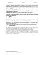
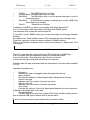
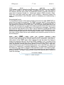
The result was good, as it is possible to see in picture 1, by using Cisco's protocol
(EnergyWise) it is possible to save up to 55% of power.
Picture 1 show the test activity, the first test (The one with no EnergyWise) is in
black, in contrast the second test is in red.
The first one is almost flat because the IP Phones consume almost the same energy. However when a call is performed or the speakerphone is on the IP Phones
consume a little bit more.
With EnergyWise the chart has columns because during the scheduling time, the
phones are switched off so they don't consume at all. The only consumption is by
the switch where the IP Phones are plugged. Cisco's next generation switch will be
capable of being switched off as well.
UTM project
– 11 / 98 –
06/06/10
_________________________________________________________________________
Picture 1: Energy Comparison
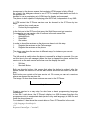
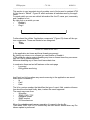
The second graph shows the consumption in Watt/Hour. (Figure 1)
Clearly the lowest column is the consumption from the second test (with EnergyWise).
EnergyWise gave us savings of at least 15% of energy.
For example, let's say you have a small company and the sum in watts of all your
POE devices is 330 and you leave them on 24/7. That's about 660 watts x 24
hours x 365 days/yr = 5,781,600 watt-hours, or 5782 kilowatt-hours.
If you're paying €0.14 per kWh, you're paying €809,48 a year to run your devices.
Let's do the same account but using the scheduler.
Let's say the scheduler switches off the device for 12 hours so 660 watts x (24-12)
hours x 365 days/yr = 5,781,600 watt-hours, or 5782 kilowatt-hours.
You are going to pay half.
To sum up, these tests were a complete success. It has motivated us, even more,
to go ahead and start to design and implement.
2.5
Project Scope
The long-term idea of the project is to develop a user friendly system in order to
manage and monitor company's equipment.
Thanks to this the company will be able to optimize energy; so this means saving
cost and maximizing the efficiently.
Moreover this means responding to green regulatory requirements and meeting
green corporate and social responsibility.
At the beginning this project was called just ―EnergyWise‖ from the Cisco protocol
and its aim was only to optimize and save energy, but during the implementation
we have included further features, such as IP phone services. Therefore the name
changed to UTM that means: Unified Telephony Management.
To sum up, the requirements of the the software are obvious. The project must be
user friendly and provide the must efficient scheduler in order to manage the device power usage.
2.6
Organization
This project was initiated by the Loccioni group.
Loccioni is a young company which provides high quality technical and environmental engineering.
UTM has been designed to contribute to the group innovation in relation to the environmental issues. Consequently Loccioni's R&D department has started look for
systems to optimize Company's energy usage. UTM is an example of this.
UTM's project Managers were Mirco Angeletti and Michele Casci.
They founded a team with two other members: Michel Uncini and Francesco Lilli;
They are students from the university of Camerino. Thanks to this experience, they
hop to get their bachelor.
They are also responsible to the project life cycle.
To sum up:
Project Managers
▪
▪
Mirco Angeletti
Michele Casci
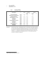
Project group
Name
Period
Availability
UTM project
– 13 / 98 –
06/06/10
_________________________________________________________________________
Michel Uncini
Franciesco Lilli
2.7
15/02/2010 from 15/06/2010 100,00%
15/02/2010 from 15/06/2010 100,00%
Communication
Communication has a great relevance in this project.
In order to
• Coordinate people
• Discover and solve problems
• Manage expectations
• Resolve conflict
• Exchange ideas
Everyone involved in the project must follow these guidelines.
As well the company culture leaves its employees to follow their own ideas and
take responsibility.
Meetings between Project groups and Project managers were weekly on Friday
with the aim of checking project status.
Brainstorming was used extensively on the project.
2.8
Worked Hours
In order to calculate the worked hours, each member of the project group after
each week, sent by email to the project managers how many hours they had
worked.
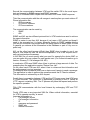
The format was:
Recipient: Mirco and Michele
Object: Name Last name – Project name code – hours.
Text: Must be empty.
Planned
working
time per
member
4
0
4
0
4
0
4
0
4
0
4
0
4
0
4
0
4
0
4
0
4
0
4
0
4
0
4
0
4
0
4
0
4
0
6
8
0
UTM project
– 15 / 98 –
06/06/10
_________________________________________________________________________
3
Overall Description
3.1
Product Perspective
This project is a component of a large system named: UUDM&M.
UUTM&M or Unified User Device Management & Monitoring is a suite made up of
services with the aim of monitoring and managing consumption by devices within
companies.
Services are:
•
Databases: Company address book management, inventory of devices,
user organization chart. It's integrable with Companies ERP and Active Directory.
•
ToTeM: Collecting and analysis of phone usage.
•
Reporting: Phone energy consumption and call usage and integration with
the intranet.
And now our project:
•
◦
UTM
IP Phone Services: Presence, ClickToDial, Text Message etc.
◦
Energy Wise: Energy consumption and management.
UUDM&M
We are very proud about of this suite, having a single unified platform where it is
possible to monitor and manage a wide range of devices is a great challenge and
means better reliability and cost saving.
To sum up the foregoing since UTM is an R&D product it changes as appropriate
therefore we don't have fixed ideas where it will run yet.
The main idea depends on the size of the company. If the company is small or the
devices to monitor are limited, the application will run in a backHoff screen.
The backHoff is a touch screen monitor, from where you can control and monitor
devices by clicking. Devices are shown on a floor plan of the company.
On the other hand if the company is bigger, one or more backHoffs isn't a good option therefore UTM will run in a Windows pc or in a Windows server. Devices are
shown by rows in a list.
In both cases employees can connect to UTM through the Intranet.
3.2
Product Features
The main UTM features are
•
device monitoring / managing
•
device scheduling
•
extending the IP Phone services
All these features must be available in a single platform and be user friendly.
The platform must be capable of monitoring devices' power consumption and
scheduling them when they are not used.
Moreover it must have the ability to retrieve device information for instance if the
device is an IP Phone its owner and its numbers are shown. As well with its energy
consumption and other critical parameters.
In addition, employees connected to the application through the intranet are capable of setting their own devices' schedule as well as retrieving device information.
Furthermore the IP Phone services are extended allowing Admin and Intranet users to send messages, call numbers, notify phones. From their IP Phones employees are able to retrieve information like: pay details, view news and so on...
IP Phone services extension allows employees to communicate more easily and to
share information and news faster.
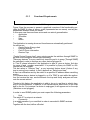
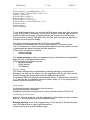
The figure 2 summarizes UTM features and its actors: Admin and Intranet user.
UTM project
– 17 / 98 –
06/06/10
_________________________________________________________________________
Picture 2: UTM uses case
3.3
User Classes and Characteristics
To work properly this product must be started by a network administrator because
during the wizard step, you have to insert several network parameters.
For instance you have to know in which switch the IP Phones are plugged, their IP
address and all the network credentials. (See the User Documentation for further
details.).
The administrator is the one that sets in which department the devices belong and
what scheduling the department has.
Moreover the administrator sets the device's position in UTM's floor plans so they
will be visible the next time the application is started.
On the other hand there are the Intranet users; in fact all the employees or whoever can reach the intranet can connect to UTM in order to retrieve critical information about their IP Phones and modify their device's default scheduling (Set up by
the administrator) in according with their needs.
For example assume that a technician has to work abroad for two weeks. He
doesn't need his office phone consequently before he leaves, he will log into the
Intranet and modify its IP Phone scheduling in order to leave it turned off while he
is out.
3.4
Operating Environment
The application can run in a small or a big company.
Clearly in a big company where there are a lot of devices it could be difficult use
the feature: ―Device over map‖ because a big company has a lot of devices and
putting them on each company's floor plan it's too much hard work.
For this reason there is also the feature: ―Device over list‖ where all the devices
are put in a sorted and categorized list.
Thanks to the search box you can filter devices by owner or department.
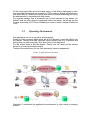
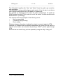
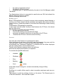
Picture 3: Application environment
Illustration 3 summarize the application's environment in other words a company
network.
UTM project
– 19 / 98 –
06/06/10
_________________________________________________________________________
The cylinder in the centre represents a typical company's Ethernet where data
passes and devices are plugged.
The devices considered are:
•
Cisco Communication manager V7 or higher (Call manager)
Used to save all the information regarding the IP Phones.
The application can retrieve information about a device's owner and phone numbers from its MAC (more then one number is allowed for the same device).
To have a call manager iis not mandatory because UTM doesn't use only the IP
Phone.
Not having a call manager means not having any IP phones as well so the IP
phone services features don't make sense.
•
Cisco Communication manager V4 (Call manager)
the use of this version is deprecated because it is no longer supported by Cisco,
however it is possible run the application and perform the same operations.
•
SOAP DB
Is attached to the CCM 7 and is used to store the Call manager information like
the devices registered, their number and owner and so on.
•
SQL DB
Is attached to the CCM 4 and contains the same information as the SOAP DB. It Is
different because unlike the CCM 7, it runs on Windows so the first idea was use a
Windows component like is SQL DB. On the other hand CCM 7 runs on linux and
it has not any SQL DB.
•
SQLserver
or EnergyWise Database from the picture. The application uses a SQL Database
because it has to save critical information like: switches, companies, floor plans
and all the scheduling information.
As well the phone's status in order to use the feature ―Ip Phone presences'
•
switches POE
All the devices monitored and managed are plugged into switches.
They are plugged in cascade and thanks to the Cisco CDP3 from any switch you
can know its neighbours.
The switches have to be POE and its IOS has to include the EnergyWise module
in order to accept and execute the SNMP request sent by UTM
•
IP phone series 70XX or higher, WebCam POE, AP POE and Windows
computers
They make up UTM's devices. In other words they are monitored and scheduled.
•
Windows XP, Vista, 7
Is where the UTM application runs and is controlled by an Administrator
3.5
Assumptions, Dependencies and Constraints
An Assumption is something that we cannot establish as being true at this point in
time, but is likely to be true.
In a project we make assumptions like in real life, because it is necessary to go
ahead in spite of lack of information, otherwise If we wait until it is available, we
would probably never start.
Most of UTM is based on Cisco's EnergyWise protocol so we assumed that will be
available and fully supported for a long time.
3
http://en.wikipedia.org/wiki/Cisco_Discovery_Protocol
Actually this is a higher risk because EnergyWise protocol is very young and is not
implemented at all by some devices.
For instance lets take an IP Phone from Cisco series. It implements some of EnergyWise but not all.
In fact it misses several levels from the protocol feature: ―EnergyWise Level‖.
In accordance with the protocol devices should be able to be set on 10 different
levels of energy, where level 0 means shutdown and level 10 means full energy,
the levels between 10 and 0 optimize the energy as appropriate. However this device can assume only two levels 0 or 1, full or no energy.
Unfortunately Cisco has not started to produce that kind of device yet, although it
will do soon.
During the phase: ―Project analysis‖ we have also analysed project constraints.
Two types of constraint were raised: time constrained and resource constrained.
The first one was the most important and we faced it all the time. It is the ability to
finish the project in time.
In our case it is very important because this project came from R&D department
and developing a new product from a new technology means being first in the
market and attracting new customers before others.
The second one, a project is resource constrained if the level of resource availability cannot be exceeded.
The focus of scheduling in these situations is to prioritize and allocate resources in
such a manner that there is minimal project delay.
UTM project
– 21 / 98 –
06/06/10
_________________________________________________________________________
4
Configuration Management
4.1
Reference Documents
•
SQLserver :http://technet.microsoft.com/it-it/library/bb418491.aspx
•
WireShark : https://www.wireshark.org/docs/wsug_html_chunked/
•
CallManager
V.7
:
http://www.cisco.com/en/US/products/sw/voicesw/ps556/prod_installation_guides_
list.html
4.2
•
Responsibility
The project manager has the overall responsibility for the SCM4.
Tasks of the SCM group:
•
Creation and management of the project's software baseline library
◦
Responsible: Mirco Angeletti
•
Management of the access to the software baseline library
◦
Responsible: Michele Casci
•
Updates of the software baselines
◦
Responsible: Mirco Angeletti
•
Creation of products from the software baseline library
◦
Responsible: Michele Casci
4.3
Component, Tools and Products Used
The following development platforms are used in the project:
•
Windows Xp
•
Windows Server 2003
•
SQLserver
•
VisualStudio
•
PSPad V 4.5.4
•
VMware
•
Call manager V 7
•
WireShark
•
The following tools are used in the project:
•
•
•
4
StarUML
Microsoft Visio
Buzan iMindMap
http://en.wikipedia.org/wiki/Software_configuration_management
•
•
Keynote 2009
OpenOffice 3.2.0
4.4
Id
Milestone
Description
Responsibl
e
Plan
Project Description
Requirement Specification
Design Description
Implementation V.Cisco
Verification
Validation
Implementation V.Indesit
Verification
Validation
Implementation V.1
Verification
Validation
M&F5
M&F
M&F
M&F
M&F
M&F
M&F
M&F
M&F
M&F
M&F
M&F
28 2
73
21 3
11 4
11 4
11 4
25 4
25 4
25 4
16 5
16 5
16 5
Comment:
5
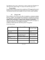
Activity Plan
Finished week
Forecast
Actual
Week +/Week
+/28 2
28 2
73
73
21 3
21 3
11 4
11 4
11 4
11 4
11 4
11 4
25 4
25 4
25 4
25 4
25 4
25 4
16 5
16 5
16 5
16 5
16 5
16 5
Finished week: Plan = original plan; Actual = week when it was actually available;
Forecast Week indicates the estimated finished week; Forecast indicates changes in
the estimation compared to the previous project report; Actual is the actual week
delivered. “+/-“ indicates the difference between Plan and Forecast or Actual, that
is if Plan is 14 and Actual is 16, then Metr will be +2. To be filled in when the
milestone is reported as completed;
M&F is Michel Uncini and Francesco Lilli.
UTM project
– 23 / 98 –
06/06/10
_________________________________________________________________________
4.5
Gant diagram
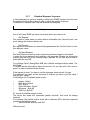
Picture 4: Gantt diagram
Picture 4 is a bar chart called Gantt diagram. It shows a project schedule, the start
and finish dates of the terminal elements and summary elements of a project.
Terminal elements and summary elements comprise the work breakdown structure
of the project. UTM used Gantt charts to show current schedule status using percent-complete shadings and a vertical "TODAY" line.
UTM Gantt diagram is made up by 7 phases:
•
Project analysis
This phase gave to us an abstract idea about UTM scope and how it basic functionality.
•
Requirement Analysis
Here most the time was spent in research. The aim was to find as much information as we could. At the end of this phases we came out with several requirements
ready to be developed.
•
Design
In this phases we started to define each object and drew class diagram.
Moreover we defined class method and attributes.
•
Implementation
This is the part of the process where we actually program the code.
•
Verification
In this phases we tested the code already done.
Moreover it allow us to ensure that defect was recognized and corrected.
•
Validation
This phase was carry out by us and clients. In order to check that UTM design satisfies and fits the intended usage. For instance if we built the right product.
•
Documentation
In documentation phase we wrote text to explain how UTM operate and how use it.
Furthermore this document will be used by who will continue UTM and maintain it.
This document was write from the begin to the end. In order to catch everything.
4.6
Project risks
Risk is defined in ISO 31000 as the effect of uncertainty on objectives (whether
positive or negative). Risk management can therefore be considered the identification, assessment, and prioritization of risks followed by coordinated and economical application of resources to minimize, monitor, and control the probability and/or
impact of unfortunate events or to maximize the realization of opportunities.
This project come from R&D department consecutively the risk is very higher because its environment is very unstable and uncertain.
In addiction UTM is based on a new Cisco protocol: ―EnergyWise‖.
A list of other risk are
Risk
Bad communication within the
steering group
A project member is sick
A project member leaves the
project
Problems with tools and
technology
Cisco's EnergyWise protocol
fail
Scheduler Fail
Potential Effect
Preventive /
Corrective Action
Project runs inefficiently
Talk and minimize the
problem
Some tasks are not done in time Delay the deliver time
Project scope must be decreased / Provide the best
some tasks need to be repossible environment
distributed to members
Some tasks are not done in time Don't be shy and ask for
help
Project fail
Find a new protocol
Some devices are shutdown
Risk table
Deactivate the scheduler
and turn on all the
device by one click.
UTM project
– 25 / 98 –
06/06/10
_________________________________________________________________________
4.7
Deliverables
Before UTM is born, it was made up by three deliverers. Them was basically since
we realize what we did wrong. And we understand all the project errors.
The first delivers was did for the project managers, the second for Cisco's employees and the last for a company which is called Indesit.
To
Output
Project Manager Requirements Specification
Cisco's employees Software V.0.1 (Verification &
verification)
Indesit
Software V.1 (Verification &
verification)
Comment:
Planned
week
28 - 2
4-4
Promised Late + Rem
week
28 - 2
1
1
4-4
0
2
9-5
9-5
0
3
Required week = week when it is required by the project; Promised week indicates
when the From expects to deliver; Late + indicates a discrepancy between
Required week and Promised week; Received week is week when it was actually
received; Rem is a remark index number.
For example 28 2 means the 28th week of February.
5
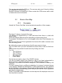
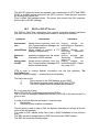
System Features
This section illustrates the major services provided by the product. Each features
is divide by three part: Description and priority, Functional requirement and Stimulus/Response Sequences.
The first part provide a short overview and basic concept of the features. The second part often is explained by a uses case since it show the system's behaver as it
responds to a request that originates from outside of that system. In other words, a
use case describes "who" can do "what" with the system in question.
The last part show the sequences of user actions and system responses that
stimulate the behaver defined for this feature.
5.1
SNMP
5.1.1
Description
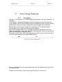
SNMP is a network protocol, it is a component of the Internet Protocol suite as defined by the Internet Engineering Task Force (IETF)6.
An SNMP-managed network consists of three key components: managed devices,
agents, and network management systems (NMS).
•
Managed devices
◦
Contain an SNMP agent and reside on a managed network.
◦
Collect and store management information and make it available to NMS by
using SNMP.
◦
Include routers, access servers, switches, bridges, hubs, hosts, or printers.
◦
In UTM the managed device are: Switch EnergyWise and PC.
•
Agent
◦
A network-management software module, such as the Cisco IOS software,
that resides in a managed device. An agent has local knowledge of management
information and makes that information available by using SNMP.
•
Network Management Systems (NMS)
◦
Run applications that monitor and control managed devices. NMS provide
resources required for network management.
◦
In this case of study UDM is a NMS
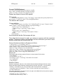
Figure 5 illustrates the relationship between the managed devices, the agent, and
the NMS.
Picture 5: SNMP
overview
The manager and agent use a Management Information Base (MIB) and a relatively small set of commands to exchange information.
A long numeric tag or
object identifier (OID) is used to distinguish each variable uniquely in the MIB and
in SNMP messages.
6
UTM project
– 27 / 98 –
06/06/10
_________________________________________________________________________
SNMP uses five basic messages
•
GET
•
GET-NEXT
•
GET-RESPONSE
•
SET
•
TRAP
to communicate between the manager and the agent. The GET and GET-NEXT
messages allow the manager to request information for a specific variable. The
agent, upon receiving a GET or GET-NEXT message, will issue a GETRESPONSE message to the manager with either the information requested or an
error indication as to why the request cannot be processed. A SET message allows the manager to request a change be made to the value of a specific variable
in the case of an alarm remote that will operate a relay. The agent will then respond with a GET-RESPONSE message indicating the change has been made or
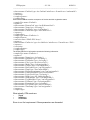
an error indication as to why the change cannot be made. The TRAP message allows the agent to spontaneously inform the manager of an "important" event.
As you can see, most of the messages (GET, GET-NEXT, and SET) are only issued by the SNMP manager. Because the TRAP message is the only message
capable of being initiated by an agent, it is the message used by DPS Remote Telemetry Units (RTUs) to report alarms. This notifies the SNMP manager as soon
as an alarm condition occurs, instead of waiting for the SNMP manager to ask.
Picture 6: SNMP interactions
A Management Information Base (MIB):
•
Presents a collection of information that is organized hierarchically.
•
Is accessed by using a network-management protocol, such as SNMP.
•
References managed objects and object identifiers.
Managed object—A characteristic of a managed device. Managed objects reference one or more object instances (variables). Two types of managed objects exist:
•
Scalar objects—Define a single object instance.
•
Tabular objects—Define multiple-related object instances that are grouped
together in MIB tables.
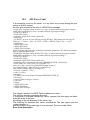
Object identifier (or object ID)—Identifies a managed object in the MIB hierarchy.
The MIB hierarchy is depicted as a tree with a nameless root. The levels of the
tree are assigned by different organizations and vendors.
Picture 7: Mib Tree
As shown in Figure 7, top-level MIB object IDs belong to different standards organizations while low-level object IDs are allocated by associated organizations.
Vendors define private branches that include managed objects for products. Non
standard MIBs are typically in the experimental branch.
A managed object has these unique identities:
•
The
object
name—For
example,
iso.identifiedorganization.dod.internet.private.enterprise.cisco.
temporary
variables.AppleTalk.atInput
or
•
The equivalent object descriptor—For example, 1.3.6.1.4.1.9.3.3.1.
SNMP must account for and adjust to incompatibilities between managed devices.
Different computers use different data-representation techniques, which can compromise the ability of SNMP to exchange information between managed devices.
But why the application need SNMP?
•
•
•
•
•
Switch Off / On Devices
Energy monitoring
Devices discovering
retrieve device's information
Realtime update (Trap listening)
To work properly the switches should implement the right IOS (see Hardware &
Software requirement) in order to understand and to response the application requests.
In order to make the devices information available the switch (Managed Device)
has an Agent which knows how its Mib (kind of database) is structured and how to
responds when a SNMP request arrives (from UTM).
The Mib structure is defined by CISCO-EnergyWise-MIB7.
It's a text file where the ―Managed objects‖ are specified.
Each object has several fields like: description, OID8 numbers, access type and
accepted value. And also whether it is a scalar object or is a tabular object.
In order to get or set any object you have to specify the right OID plus the value to
set.
For example to switch off a device you have to:
1.
2.
3.
4.
5.
Find the right name: CewLevelEntry
Verify the access type: R/W
Find the OID : 1.3.6.1.4.1.9.9.683.1.6.1.10
Set the message: In my case I'm going to set it to 1 (No energy).
Send the request by SNMP
Picture 8: List of cisco-EnergyWise's MIB
Figure 8 shows how CISCO-EnergyWise-MIB is structured. That picture is taken
from Ireasoning9 an open-source Mib browser.
7
http://www.oidview.com/mibs/9/CISCO-ENERGYWISE-MIB.html
http://www.paessler.com/support/kb/questions/49
9
http://www.ireasoning.com/
8
UTM project
– 29 / 98 –
06/06/10
_________________________________________________________________________
Thanks to SNMP we were capable of creating a ―User-Friendly‖ application since
SNMP is easily implementable by using a hight language program like C# or Java.
Due to Company's politics we decided to use C#, because it is feasible and easy
to be integrated.
Moreover UUTM&M is written in C#.
In addition another SNMP duty is to listen for incoming switch's traps.
Traps are sent when any events in a switch are raised. For instance when a device is plugged or unplugged.
Catching TRAP allows UTM to know the current state of any devices.
During the ―Requirement analysis‖ before the SNMP idea came up, we considered
different alternatives like:
•
Telnet
•
SSH10
•
Hyper terminal
All of them are good alternatives but none of them can be implemented by a high
programming language since they can be used only by CLI11.
SNMP is not only used between switches and application. In fact you can use it
with the Call manager too.
You can query the Call Manager in order to retrieve IP Phones information like:
•
IP Phone owner
•
IP Phone numbers
So whenever the application has to associate IP Phones with their owners or its
numbers it has to use SNMP (the same request can be done by AXL too).
For further information see the section: Appendix B: ANALYSIS MODE.
In conclusion SNMP is the most important application feature. Thanks to it we are
capable of retrieving any kind of information. (Specified in the MIB) e,g.: device
name, energy consumption and so on. The next step will be to improve this feature
and become as fast as possible.
10
11
http://en.wikipedia.org/wiki/Secure_Shell
http://en.wikipedia.org/wiki/Command-line_interface
5.1.2
Functional Requirements
Picture 9: SNMP usage, uses case
Figure 9 has the purpose to present a graphical overview of the functionality provided by SNMP in terms of actors, goals (represented as use cases), and any dependencies between those use cases.
In this uses case there are three actors and one actor's generalization:
•
Application
•
Scheduler
•
User
◦
Admin
The Application is running alone and its actions are automatically performed.
Its actions are:
•
Create Device Energy chart
•
Discover devices
•
Find IP Phone information
•
Receive Trap
―Create Device Energy chart‖ every minute queries the switches through SNMP to
get how much energy its devices are consuming.
―Discovery devices‖ is a very useful tool since the goal is to query (Through SNMP)
the switches in order to discover any other devices plugged in.
In ―Find IP phone information‖ the application is able to: given a device, find who
its owner is and numbers associated. It Is possible by query via SNMP or AXL
request the Call manager.
The last action is ―Receive Trap‖, a very important feature since it listens if any
trap is coming from a switch. In fact it depends on ―Switch send trap‖.
A trap is a notification sent by the switch to a specified IP address when something
occurs.
For instance when a device is plugged in or off a TRAP is sent while the application first receive the trap, second extracts the trap and finally analyses and execute the correct actions.
Thanks to this feature the application is able to log on in real time to what is happing in the environment, in addition it can refresh device status both on the map
and on the list. For instance if a device is unplugged, it will appear red on the map
(Shutdown or not plugged).
In order to send SNMP packet you must respect the following parameters:
•
Host
The switch IP. Is unique in a network
•
Community
Is a switch password, you need that in order to use switch's SNMP services.
•
Port
Together with the host, define a Socket.
UTM project
– 31 / 98 –
06/06/10
_________________________________________________________________________
The ―Scheduler‖ together with ―User‖ and ―Admin‖ have the goal to get or set device information.
The scheduler is a timer which elapses each minute. It has the aim to set device
level in accord with policies set by the admin or Intranet user.
For example an employee has to leave the office unexpectedly. He sends an
SNMP request through UTM in order to turn off his device. In other words he sets
device level to 1 (no energy).
This scenario can throw exception if the following occurs:
•
Host is unreachable
•
Community string is wrong
•
Port is closed
Whatever happens, the admin is advised to reinsert commands again by UTM..
Likewise it is possible that the network parameters are correct but the switch is
shut off so the admin can verify that by sending a PING12 packet again through
UTM.
Moreover he can check if any ports are opened by using the utility ―Verify port‖.
12
http://en.wikipedia.org/wiki/Ping
5.1.3
Stimulus/Response Sequences
In this paragraph I'm going to explain in detail how SNMP requests are sent over
the network and how the product is able to catch the switch's response.
Furthermore it explains how Trap are received and analysed.
Picture 10: SNMP get/set request/response
First of all in any SNMP you have to set what action you want to do:
•
Get Request
Get request is used when you want retrieve information like: Device's level, how
much energy the device consume etc..
•
Set Request
Set request is used when you want setting parameters like: Device's level or interface device's name.
•
Get Next Request
Get Next Request is used in order to discovery devices plugged in the switch.
It works like a get request but in addiction, the response contains the information
required and the OID of the following object required. So you can send a new request with the new OID.
For instance Cisco's EnergyWise MIB has a tabular managed object called: ―CewEntTable‖.
It contains all the informations about its devices. So you can send ―Get next request‖ in order to retrieve all the devices.
If the request Is a set. You have to set the message value too and its type.
For instance if you want set the new level of a device you have to put the value 1
and the type ―Integer‖.
Is following a list of available types in byte:
•
•
•
•
•
•
Integer - Byte 2
Byte string - Byte 4
Null - Byte 5
Object Identifier - Byte 6
Sequence - Byte 48
TimeTick - Byte 67
Of course is possible erring in errors.
The errors are inside the responded packet received. And must be always
checked.
For instance if the switch receive a get with a unknown OID it send the response
containing the following error:
•
―NoSuchName‖ with the code 0x3.
Other error are
UTM project
– 33 / 98 –
06/06/10
_________________________________________________________________________
•
•
•
•
•
―TooBig :
The SNMP packet is too large.
―NoSuchName‖:The MIB object does not exist.
―BadValue‖:
The MIB object value is not the proper data-type or is not in
the proper range.
―ReadOnly‖:
A SetRequest message is attempting to modify a MIB entry
with Read-only privileges.
―GenErr‖:
Generic error condition.
In addition in a SNMP you have to put another field called: Request-ID.
It is a 4-byte integer value that uniquely identifies each SNMP packet.
The response must contain the same request-ID.
To conclude, in each SNMP packet you can put more than one message (Variable
binding).
At maximum ten. Each variable contain: OID, message type and message value.
Clearly the response contain the same numbers of variable binding.
This is a optimization technique since it reduce the numbers of packet sent. Also
UTM speed.
Picture 11: SNMP trap
Picture 11 show through a state chart how UTM is listening for SNMP trap.
How is possible view, the application waiting a trap after be started.
It move to the state: ―Host analysing‖ when a trap is received.
In this state the trap is analysed and discard if is unknown.
After this state the trap is extracted and the informations found are made available
to UTM.
Important information are:
•
Enterprise
◦
Identifies the type of managed object that generates the trap
•
Agent Address
◦
Provides the address of the managed object that generates the trap
•
Generic trap type
◦
Indicates one of a number of generic trap types
•
Specific trap code
◦
Indicates one of a number of specific trap codes
•
Time stamp
◦
Provides the amount of time that has elapsed between the last network reinitialization and generation of the trap
•
Variable bindings
◦
The data field of the trap that contains PDU. Each variable binding associates a particular MIB object instance with its current value
Picture 12 show an incoming trap captured by an network sniffer.
Picture 12: Trap device plugged in
5.2
IP Phone Services
5.2.1
Description
In this paragraph I'm going to explain the following topics:
N.B: The point from 1 to 3 and 5 can be skipped if the reader already have basics
acknowledgement about the IP Phone but is vividly recommended.
1.
2.
3.
4.
5.
An overview of the network architecture the Cisco Call manager uses
The Cisco IP Phone
The XML message format used by Cisco IP Phones
Brief description of the IP Phone services features
Resources for further study (Can be found in XXX section)
Cisco Call Manager Architecture:
Picture 13: Network component
The pieces we are concerned with are:
• Phone This is an IP Phone. The Cisco IP Phones used by Call manager at this
writing include
the 7960, 7940, and 7910 models. A typical system has hundreds or thousands of
phones.
• Call manager Call manager is a Linux server running Cisco's Call manager software
packages. Although only one Call manager is shown in the figure, a standard corporate
installation has at least two and as many as five Call managers in a cluster.
• Web server This designation is for a Web server on the same corporate network
as the IP
phones and manager. It is linked with the software.
• Web server This Web server is outside the corporate network and supplies content
developed by a third party.
• Desktop PC This is a normal desktop PC, where UTM application is running.
The Call manager is a software-based call-processing develop by Cisco System.
CUCM is able to track all active VoIP13 network components these include phones,
gateways, conference bridges, transcoding resources, and voicemail boxes
among others.
Call manager often utilizes the Skinny Client Control Protocol (SCCP) as a communications protocol for signalling the hardware endpoints of the system, such as
IP Phones.
13
http://en.wikipedia.org/wiki/Voice_over_Internet_Protocol
UTM project
– 35 / 98 –
06/06/10
_________________________________________________________________________
H.32314, Media Gateway Control Protocol (MGCP)15 or Session Initiation Protocol
(SIP)16 is used to pass call signalling to gateways.
The call manager used by the software is Version 7 or superior.
The Cisco IP Phone is shows in figure 15
Picture 14: IP Phone
The phone communicates with Call manager using the Skinny protocol17.
All the operations needed to place phone calls, retrieve voice mail, put calls on
hold, and so
forth are initiated and/or modulated by the exchange of Skinny messages between
the phone and
Call manager.
Likewise, all the voice data that goes in or out of the phone is sent via e streams 18.
The phone has
the ability to listen to multiple streams, issue multiple streams, and mix streams in
the phone. The
phone supports G.711 and G.729 streams. G.711 is the primary format for voice
data on the Public
Switched Telephone Network (PSTN), while G.729 is a low-bandwidth format typically used over a
corporate network during toll bypass.
How and why the IP phone are able to communicate with any other compatible device on the network.?
When the engineers at Cisco were working on the concept of Cisco IP Phone services, they started
with a blank slate. The first question to solve was how the phones would communicate with other
computers in order to deploy services. The best fit seemed to be to let the phones
act as browsers,
with the service suppliers acting as Web sites.
Web browsers and servers operate in a client/server fashion and communicate by
sending data using the HTTP protocol. The protocol is fairly simple and is successfully deployed on a variety of platforms.
Initially, the phone was set up to have an HTTP client that it would use to access
data on external Web servers.
Unfortunately, the phone is only able to give up a 132 by 64 pixel window for services, which
completely rules out using Web pages created for conventional PCs. In addition,
the limited
14
http://en.wikipedia.org/wiki/H.323
http://en.wikipedia.org/wiki/MGCP
16
http://en.wikipedia.org/wiki/Session_Initiation_Protocol
17
http://en.wikipedia.org/wiki/Skinny_Call_Control_Protocol
18
http://en.wikipedia.org/wiki/Real-time_Transport_Protocol
15
horsepower in the phones means that rendering HTML pages is fairly difficult.
As a result, the designers chose to use HTTP to transport data back and forth to
the phones, but
decided to use a proprietary set of XML tags for display and command.
The phone is also capable of displaying pure ASCII text, independent of any XML.
In UTM context the IP Phone services can be showed in the IP Phone by two
ways:
•
retrieve from a web server
•
Pushed by the application
In the first one is the IP Phone that query the Web Server and get a service.
For example you can create a list of services in the web server like:
•
Message of the Day
•
Address Book
•
Read Mail
•
Get orders.
In order to show this services on the phone we have to do this step:
1.
Register the services on the Call manager
2.
Register the services on the phone
The phone can show the services in different ways, for instance you can set:
•
Idle mode
The Idle mode is switch when the phone is unused for at least x seconds (You can
set this time in the call manager) when the time is elapsed the phone contact the
service url on the web service and show over the display the result.
•
•
Soft-key
Services Button
Both are phone's bottom, this means that when the button is pushed, after the
phone contact the service url on the web service and show the result on the display.
Each button can contain at list one service url. Of course you can set a services
where are showed the services list.
The image 16 show how those services are seen in the IP Phone:
Picture 15: Ip Phone services
Create a service is a easy step for who have a basic programming language
knowledges.
In fact like I said above, the IP Phone's display is a XML browser therefore the
programmer duty is encapsulate data (wrote in any web language) in XML file and
leave the phone parse is.
For instance if I want show the current data on Cisco IP Phone this is the code:
<%@ Language=JavaScript%>
<%
Response.ContentType = "text/xml";
UTM project
– 37 / 98 –
06/06/10
_________________________________________________________________________
Response.Write("<CiscoIPPhoneText>\r\n");
Response.Write("<Title>Get Data</Title>\r\n");
response = Date.Now();
Response.Write( response );
Response.Write("<Text>\r");
Response.Write("\r</Text>\r\n");
Response.Write("</CiscoIPPhoneText>\r\n");
Response.Flush();
Response.End();
Session.Abandon();
%>
To see what happens when you execute this Web page, make sure that you have
a copy of this code in a directory on your Web server. You should then be able to
invoke the Web server using a browser and see the output from the Web page.
The phone then treats the text defined for the Title and Text tags and lays the information out on the phone display.
The other way to push services on a IP Phone is using UTM.
In other word UTM contact the IP Phones by sending HTTP request to them.
The IP Phones have to listen incoming request and use their own parser in order
to understand the request and exe the right operations.
UTM provide two groups of services:
•
Instant message
•
retrieve message
The instant message is sent in a unexpected way to the phone by the application
when the user or the administrator need it.
UTM has three kind of those services:
•
Message sending
•
Notify sending
•
Call Sending
Message sending
This feature allows users or administrators sending message to employments.
Messages are sent by the admin from the application and by the user from the
intranet (anyway the intranet will contact the application automatic).
For instance UDM can advise an employments that its IP phone will be shutdown
in 10 second due to scheduler actions or admin policy, so if the employment is
present can block the action in time.
Notify sending
It's a simple acoustic sound comes from the phone.
Notifies are sent after messages.
In addition this features can be used in order to discover where a IP Phone is.
Call Sending Or Click to dial
Admin or intranet users can over the application or the Intranet put any numbers
and call it. The call will be done by their default phone.
Retrieve message works in the opposite way, in fact are the IP Phones that queries UTM web service in order to get informations.
Queries can be done in three different ways:
•
By pushing ―Application button‖
•
By pushing ―Soft-key buttons‖
•
Automatic each ―x‖ second (setted by the admi in the Call Manager) called
―Idle Mode‖
The Administrator duties is to associate for each button an URL that indicate the
address where the service is hosted.
Retrieve message services are:
Booking services
Before UTM application in Loccioni's company when somebody wanted booking a
meeting room those should call the secretary and register their name and time
range, however it raised the problem to how show the scheduling for each meeting
rooms.
Consequently UTM application solved this.
In fact it has a service called ―booking‖ linked between the IP Phone, the intranet
and the Web server.
The scenario is very easy and is the following:
1.
An user logs into the intranet
2.
Choose the meeting room and the time range
3.
Automatic the intranet refresh the url associate to the IP Phone
4.
Therefore the IP Phone show the current booking
Presences
The main aim of this feature is to employment's status.
When employments are busy or they don't want be disturbed, they can push the
―services button‖ on their IP Phone and select the state ―Busy‖.
Automatically the ―Presence's Database‖ is refreshed and the others employes
can see its busy status over the address book.
Thanks to this features employes status are well know.
Moreover the employments privacy is respected.
To conclude the possible status are
•
Available
•
Shutdown
•
Busy
•
Meeting
•
Don't
bother
If the status doesn't change for x minute automatically change in Busy:
ShutDown
ShutDown is a useful utilities used in order to sensitize employees and save energy cost.
This request is made by pushing a button on the phone. The Request goes to
UTM and it shutdown who made the request.
UTM project
– 39 / 98 –
06/06/10
_________________________________________________________________________
When the device is off you can't turn it on due to this feature has not implemented
yet on Cisco's EnergyWise protocol although Cisco will provide this features with
the new IP phone mode.
On the other hand is possible turn on the devices by logging on the Intranet or on
the application.
News retrieve
There aren't limitations of this feature it can be tailored to any particular needs!
UTM allow the IP phone to receive the following news:
•
PayCheck
By clicking a phone's button users can see their payCheck over the display. Thus
save paper cost and increase the efficiently.
Moreover you don't have to go and take the payCheck by your hand! It will come
to you wherever you are.
•
Company's news
By pushing a button you are update about company's news!
For instance you will know if there is an incoming meeting or a beach soccer game.
•
World's news
In order to get advised about what are happening in the world.
But this services can be extended, for instance you can provide the most varied
services like:
•
Things to Ponder
•
Phrases of the day
•
Day's duties
•
…
In conclusion, Cisco IP Phones expand the capabilities of the traditional phone.
While the expected phone functions are provided (call connection, transfer, conference, hold, and so on), the addition of phone services enables you to use Cisco
phones to solve complex business problems.
The IP phone services can provide companies to solve their own business needs
or the needs of their customers.
More than just a communication device, the Cisco IP Phone can be leveraged for
standard business functions including generating revenue, convenience, increasing productivity, entertainment, gaining a competitive advantage, and more. All it
takes from you is a little imagination and some code.
5.2.2
Functional Requirements
Picture 16: IP Phone services use cases
The uses case below summarize the IP Phone functional requirement.
Actors who interact with the system are:
•
Admin
•
Employee
•
Scheduler
•
Device
•
Device's Owner
The Admin is who uses and manager UTM software he runs the application.
From the application he can Call devices, Notify devices and Text devices;
All those required authentication first.
The authentication consists of Device's IP, Device's username and Device's Password;
In order to simplify the authentication, Device's Password is the same for each devices and it is set in the Call Manager when a new device is added. Otherwise you
have to ask the password each time an operation is performed.
Username and IP are not encrypted therefore in order to get them, the application
have to query the Call manager by SNMP or AXL request.
You can retrieve those by passing device's mac or device's internal because are
static information that doesn't change unlike IP and username.
An Employee is a normal company's worker, he can the company's Intranet perform the same services explained below.
In any case the services are executed by UTM.
In order to communicate UTM and the Intranet exchange UDP or TCP packets.
For example if Michel has the number: 8401 and he want send a message (ID operation = 5) that say ―Hello‖ to Francesco(he has the numbers 8402) after Michel
has filled the fields, the Intranet send an UDP packet to UTM and it says:
5@8401@8402@Hello.
Thanks to UTM's PHP thread (For further information have a look to the section:
Intranet integration and Communication requirement) the UDP packet is received,
interpreted and performed.
The scheduler before perform any operation, it will inform the device. So if device's
owner if present, may block the operation.
The device is the physic IP phone; it is associated with a meeting room instead a
user.
Beside the normal IP phone operation, it show room's schedule by query a dedicate database. The device's display is refreshed each x second.
UTM project
– 41 / 98 –
06/06/10
_________________________________________________________________________
This operation is independent from UTM application due to it queries the web
server and it receives answer from it.
The last actor is device's owner, he use the IP Phone and its services.
5.2.3
Stimulus/Response Sequences
Picture 17: Booking uses case
Figure 18 show a simple state chart that summarize how the booking service
works.
This services is showed in the IP Phone display every x second and stay still till
any buttons are pushed or the services request to be refreshed.
More precisely In UTM after 10 second the IP Phones make the request in order to
refresh the service. It contacts UTM's web server with its mac and UTM response
with phone's status.
Picture 18: Notify – Call – Message Uses case
Picture 19 show how the IP Phone carry out the following operations:
•
Notify
•
Call
•
Message
All those operation are pushed into the IP Phone by UTM AXL request.
At first when the IP Phone are turned on, It is waiting to an incoming request.
When the request arrive it is parsed and is established which type of request is finally it is showed over its display.
Picture 19: Presences -- News -- Shutdown services
Figure 20 show the rest of the services
•
Presences
•
News
•
Shutdown
UTM project
– 43 / 98 –
06/06/10
_________________________________________________________________________
This services are inside the IP Phone. The user can make use of those by clicking
on a specified IP Phone's button.
Anytime a services is clicked the IP Phone contact the UTM's server web in order
to retrieve the correct information.
5.3
Devices Over Map
5.3.1
Description
Literally the ―Device Over Map‖ show the planimetry position of the company.
Picture 20: Loccioni's planimetry
The figure 21 shows a Loccioni's floor map.
The devices are represented by a circle and below them there is a label with
owner initials.
Circles are filled by different colours depending on device energy level.
For example if the device is off or is not plugged in the colour is red otherwise it is
green.
With the new Cisco's IP Phone generation the device will be able to assume more
then two energy levels.
By holding the mouse over the devices the full owner name is shown.
This is a useful trick if you don't remember the owner name or who is in that location.
UTM services are provided for each device by clicking over them .
You can:
•
Turn On Device
•
Turn Off Device
•
Set Level (Soon)
•
Set categories
•
Delete image
The first two are used in order to Turn ON/OFF devices.
The third at present doesn't work because it has not yet been implemented by
Cisco's protocol. It will allow the admin to set 10 different levels of energy.
Moreover it is possible to set device categories. This information is used by the
scheduler.
For each category there is a different scheduling; for instance if a device belongs
to the category ―Research & Development‖ it will be powered off at 7 pm, instead a
device belonging to the category ―Commercial‖ will be powered off at 8.30 due to
the fact that the commercial department finishes later than the other department
and therefore needs power.
Finally it is possible to delete devices over the map since the employees can move
from one desk to another.
Clearly the admin can add devices over the maps.
Figure 22 shows how.
First you set the switch where the device belongs, second you choose in which
port the device is, thirdly you click to ―Choose location‖ button and finally you click
over the map where the real device position is.
Picture
21: Set Device's position
The ―Device Over Map‖ feature is in real time which means when there are any
changes in status the map is automatically updated.
If a device is being updated it will became black and the label below will show ―Refreshing‖ until UTM can establish the real device status see picture 22.
There are different kinds of events:
•
Device is turned ON / OFF
•
Device is plugged / unplugged
While the first is obvious the second is raised when the device is plugged / unplugged manually.
This service is made available by a UTM process, running in background called
―Thread trap‖.
Its duty is to listen for incoming trap (What a trap is and how it works, is explained
in the section SNMP).
Device Over Map can run in two different ways:
•
Application
•
Touch-screen monitor
An idea may be to run Device Over Map feature over a Touch-screen monitor.
This monitor is positioned in specific locations. For instance you can set the monitor in a room and leave device over map showing room planimetry and devices.
Thanks to the Touch-screen it is possible to touch any device and perform any operations.
This mode-view is very nice and user-friendly.
In addition it allows any employee to have complete control of all devices present
in the rooms.
Consequently the devices are well monitored. Furthermore you need just a single
point of control capable of controlling any devices present.
In other words this feature optimizes energy cost.
Picture 22: Demo Desk
The image above is taken from UTM during the implementation phase.
It shows our demo desk where all the services and functionalities were tested.
The demo was composted by:
•
Three IP phone devices
•
One computer
UTM project
– 45 / 98 –
06/06/10
_________________________________________________________________________
5.3.2
Functional requirement
The following uses case show this feature requirement.
The actors who interact with the system are:
•
Employee
•
Admin
•
Monitor
•
Thread Trap
Picture 23: Device Over map requirement
The previous uses cause can throw different exceptions.
Like the following:
•
•
•
•
•
Device not found
Device operation not performed
Device name or numbers not retrieved
Monitor doesn't show any devices
Trap not received
The first one is thrown when the admin want to add a new device over the map,
the possible causes are
•
Device non existent
•
The switch where the device is plugged doesn't answer
Therefore the admin should check if the field inserted is correct and the device is
in the correct switch.
If any operation (Turn on / off...) is not performed the only cause could be switch.
The switch could fail for many reasons:
•
UDP packet is lost
•
The switch is restarting
•
The switch is off
The first exception is possible but very rare because the probability of losing any
UPD packet is very low therefore you should retry later.
For the other exception you show check the switch status.
The device name and numbers are retrieved from the Call manager by passing
devices mac (The only information that is static and doesn't change) Therefore if
any exception is raised the only cause is the call manager. Maybe it is refreshing
or it is momentarily shutoff. Consequently you should contact the administrator.
If the trap is not received the possible causes are
•
Switch is misconfigured
•
Switch is down
•
The application trap is down
The switch configuration in order to send trap notification must have enabled the
SNMP services.
Appendix Z FAQ explains how to configure it.
UTM project
– 47 / 98 –
06/06/10
_________________________________________________________________________
5.3.3
Stimulus/Response Sequences
Trap received and map refreshed
Picture 24: Refresh devices over map
Picture 25 shows how UTM refreshes devices over the maps.
Devices must be refreshed when they change their status for instance when they
are turned on or off, plugged or unplugged.
Those changes are notified by the switch where the devices are plugged by sending Trap thought SNMP packet. UTM in order to listen for incoming trap has a
thread dedicated to it.
When trap arrive, they are analysed. Since there are different kinds of trap If UTM
receives an unexpected trap it is discarded. Otherwise the trap is analysed and
thanks to its information UTM can find the device on the map that raised the trap
and refresh it with the new status.
It can happen that the device is not found so the trap is discarded and the admin is
notified. This situation occurs when a new device is plugged but not yet put on
map by Admin.
If the device is found, UTM checks how much energy is being used in order to update map with correct information. For instance when the device doesn't consume
energy it means it is unplugged or turned off so the device is red. Otherwise if it
consumes energy it is green.
In both cases the map is refreshed. Then the system returns to wait trap.
5.4
Devices Over List
5.4.1
Description
Picture 25: Device Over list
Picture 26 show what ―Device over list‖ feature looks like.
It is a very powerful feature which can solve company problems.
There are two windows. The second is where devices are shown. If they are
dragged into the first windows you can call them. The call is made by the default
IP Phone set by the administrator and registered on the configuration file.
In both windows there are three fields:
•
•
•
Level
Name
Numbers
The Level shows the device status, it is dependent on the IP Phone service: Presences.
In fact if a phone owner changes status by using IP Phone service, the list is refreshed automatically.
Possible status are
•
Available
•
Shutdown
•
Busy
•
Meeting
•
Don't disturb
Clearly the presences feature is available only if the device is an ―IP Phone‖ otherwise the only levels acceptable are: Available and ShutDown.
The name is the real owner's name if the device is an IP phone or the name of the
tool being used e.g: ―Switch‖, ‖WebCam‖, ―Access Point‖.
To conclude the last field is ―Numbers‖ which shows the numbers associated to the
device.
In the second window a text field capable of filtering the list is available.
Device Over List is similar to Device over map but with more features:
•
Discovery
•
Plug and Play
•
Device Operations
―Discovery‖, ―Device over list‖ is able to automatically discover any devices
plugged in any switch by simply giving input of one switch.
Diagram 27 shows how the discovery feature works
Picture 26: Neighbor discovering
First of all when the discovery protocol is started, application prepare a list of all
switch interfaces.
Second each interface is examined and if any device is plugged, it is added to
the ‖Device over list‖.
Third if any other switches are connected to the given switch, all the process is
started again.
But How does the application know if a device is plugged?
We solved this problem thanks to SNMP and the Cisco's Mib.
In other words for each interface we send an SNMP request and retrieve how
much energy is being consumed (This features is also used to make energy
charts). Clearly if there is no energy consumption before excluding any devices we
must check if interface is turned off by the scheduler or any user.
As explained in ―Device Over Map‖ section; devices in ―Device Over List‖ are
automatically refreshed.
UTM project
– 49 / 98 –
06/06/10
_________________________________________________________________________
In fact it uses the same ―Thread trap‖.
Moreover thanks to the features ―Plug and play‖ when any device is plugged in
the switch, a trap is raised and caught by UTM. Then the device is put on list.
―Device Over List‖ is able to overcome ―Device Over map‖ weaknesses like:
•
Limitation in device numbers
•
manual devices entry
All the devices are shown in a list so you have a complete system environment
overview.
Moreover In order to find devices quickly the list can be filtered.
On the other hand in this beta version we found problems when the list is loaded
for the first time since it has to retrieve a lot of information from both the call manager and the switch. When the information is saved in the memory access becomes faster.
Finally in ―Device Over List‖ you can do the same ―Device over map‖ operations
like:
•
Turn ON / OFF
•
Make call (Also with the draw and drop)
•
Send Message
•
Send notification
5.4.2
Functional requirement
Picture 27: Device Over List's Uses case
Picture 28 shows the main requirements.
The actors are:
•
Application
•
User
The application is the system. When the software is started, the device list is made
up and is kept updated.
The other actor is the user who uses the program and performs the operations.
The exceptions thrown by the system are similar to those thrown by the ―Device
over map‖ therefore in this section are omitted.
UTM project
– 51 / 98 –
06/06/10
_________________________________________________________________________
5.4.3
Stimulus/Response Sequences
Picture 28: Device Over List
Picture 29, shows how the device list is created.
UTM examines each interfaces for each switches.
For each interface first check its status (For status I mean whether is consuming
energy or not), second its energy level (The energy level is set by the admin or the
scheduler and can assume 1(no energy) or 11(full energy)).
Now if the status is 0 ( no energy in that interface ) and the level is > 0 that interface is discarded since nothing is plugged there.
Then the application retrieve the old mac for that interface. Since when any devices are plugged in any interface UTM send a SNMP set request and save the
device's mac in a static SNMP field in the switch so it will remain there even the
device is turned off by the admin or the scheduler.
The mac is saved because you are capable of finding it whether the device is on
or off.
Now if device's status is 0 the interface are discarded. On the other hand if the
status is more then 0 you can by SNMP retrieve the current device's mac.
Then it is compared with the old mac and if they are different, the old MAC is synchronized with the new one.
The only case where the old mac is different from the new one is when a device is
moved from an interface to another.
The last step is take device's name and device's number's. At this point we have
anything we need so let's combine it and append over the list.
Picture 29: Device added/modified by Trap
Picture 30 shows how Device Over list is capable of being realtime.
First of all UTM has a separate thread called ―Trap thread‖.
It is used to wait incoming trap. When a trap arrives, first it is analysed then if recognized, UTM starts to look in the list in order to find the device that raised the trap.
If it is found, this can mean two things:
•
A device is unplugged
•
A device is turned on or off (By admin or scheduler)
In both cases the application checks device's energy consumption and if it is equal
to zero the device is unplugged or turned off .
In order to distinguish the two cases UTM checks the device level. If the device
level is more than zero, the device has been plugged off so it will be removed from
the list because it is no longer available in the network.
On the other hand if the energy level is 0 the device has been turned off by the
Admin or the scheduler so the device will appear red on the list.
Conversely if the device is not found in the list it means it is plugged in to an interface so it is created and appended on the list.
The thread will not stop till admin instructions.
1.
Refresh presences for each device
Picture 30: Presences refreshing
The state chart in figure 31, represents UTM states when it updates devices on the
list.
Device status are saved in a Database and each 30 seconds (you can set the time)
UTM checks if there are any changes.
2.
Query device over list
The last chart in figure 32 shows how the system filters the list, given an input by
the admin.
As soon as a single input (character) is inserted, it is analysed and the list is filtered.
If the list is empty the application continues to wait user input. If not a new list is
created and the application continues to wait user input.
If the user input is incomprehensible an error message is shown.
The complete list is shown when the input are empty.
Picture 31: Query device over list
UTM project
– 53 / 98 –
06/06/10
_________________________________________________________________________
5.5
ShutDownSuperior
Taken from: Lilli F.,2010 , EnergyWise technology & UUDM&M interfacing
5.5.1
Description and Priority
What Cisco EnergyWise can do is what we described so far. At least for the moment it's possible to manage the power consumption of telephones, IP-based
video surveillance cameras and not so much more devices; moreover in many devices it's not possible to specify power levels different from 0 (device shut down)
and 10 (device at full energy), even at the time of writing this thesis.
The biggest power consumers in an enterprise (like computers, routers, switches,
etc.) cannot be supervised and managed on the energy consumption field yet.
Cisco Systems is currently working on the realization of standards-de-facto and
new network protocols that will make all of this possible, one day.
It is kind of useless to say that the work done so far is not really sufficient to guarantee important and very advantageous savings inside an enterprise. The simple
operation of shutting down the phones can be an help, but way more significant
savings could be reached with the power management of devices with a huge
need for energy, such as the computers.
So we can just say: let's give Cisco some more time. But what can we do while
we're holding on?
PsShutDown: Executable
PsShutDown is a command-line utility similar to the shutdown utility from the Windows 2000 Resource Kit, but with the ability to do much more. It is part of a growing kit of Sysinternals command-line tools that aid in the adminstration of local and
remote systems named PsTools. PsShutDown requires no manual installation of
client software: in order to install the component, just copy PsShutDown onto your
executable path, and type psshutdown with command-line options defined below.
This
executable
program,
freely
downloadable
from
Internet
at
http://technet.microsoft.com/en-us/sysinternals/bb897541.aspx, allows users to
make the following operations on Windows computers:
•
•
•
•
•
•
•
suspension;
hibernation (requires Windows 2000 or higher);
poweroff;
lock (requires Windows 2000 or higher);
logoff;
reboot;
shutdown without poweroff.
Moreover it's possible to specify the collection of computers on which to perform
the shutdown, the operations timeout and much more. Of course in order to take
advantage of these services on remote computers there are some requirements to
obse
1.
the user who launches the application should know the IP address or the
PC's name on which to make the desired operations;
2.
the computers should be connected through a network in some way;
3.
the user who wants to make these operations should have the permissions
to do it.
Regarding the point 3. : if the application's user does not have administrator permissions, or in general not enough permissions, he will not be able to do anything
on remote PCs but only on the user's one.
UTM project
– 55 / 98 –
06/06/10
_________________________________________________________________________
5.5.2
PsShutDown: List of Commands
Picture 32: PsShutDown.exe commands
The following is the list of PsShutDown (v2.52) commands. The reader can also
find it by writing ―psshutdown.exe‖ from the Windows console.
Syntax
psshutdown -s|-r|-h|-d|-k|-a|-l|-o [-f] [-c] [-t [nn|h:m]] [-v nn] [-e [u|p]:xx:yy] [-m "message"]
[-u Username [-p password]] [-n s] [\\computer[,computer[,...]|@file]
Options
-a
-c
-d
-e
-f
-h
-k
-l
-m
-n
-o
-p
-r
-s
-t
-u
-v
computer
@file
Abort a shutdown (only possible while countdown is in progress)
Allow the shutdown to be aborted by the interactive user
Suspend the computer
Shutdown reason code (available on Windows XP and higher)
Specify 'u' for unplanned and 'p' for planned
shutdown reason codes:
xx is the major reason code (must be less than 256)
yy is the minor reason code (must be less than 65536)
Forces running applications to close
Hibernate the computer
Poweroff the computer (reboot if poweroff is not supported)
Lock the computer
Message to display to logged on users
Specifies timeout in seconds connecting to remote computers
Logoff the console user
Specifies optional password for user name. If you omit this you will be
prompted to enter a hidden password.
Reboot after shutdown
Shutdown without poweroff
Specifies countdown in seconds until shutdown (default is 20) or the time of
shutdown (in 24 hour notation)
Specifies optional user name for login to remote computer
Display message for the specified number of seconds before the shutdown. If
you omit this parameter the shutdown notification dialog displays and specifying a value of 0 omits the dialog.
Shutdown the computer or computers specified
Shutdown the computers listed in the file specified
5.5.3
PsShutDown: Usage
So far we presented what it's possible to do by using the PsShutDown Application, but we
haven't said anything about how all of this can be useful for our purposes. What we want is
not a tool manageable only by command line. A command-line tool, even if very easy to
use, remains really uncomfortable for the most of the people (specially if there are several
computers to manage: to write every time all the PCs where to operate would be just for
crazy people).
Fortunately something comes to help us: it's C#, the same language used for the rest of the
Server-side Application. With some C# lines of code we can call an executable program,
such as PsShutDown, and make it work giving to it the parameters it needs in a very comfortable way.
UTM project
– 57 / 98 –
06/06/10
_________________________________________________________________________
Picture
Picture 33:
34: ShutDown
ShutDown Application's
application's login
operation
pagepage
In particular we would like an application (or better, as we said, a “block” inside the
Server-side Application) very easy to manage, that would make us pick up the computers
we want and would make us choose all the parameters we prefer, and we want it with a as
much user-friendly as possible graphic interface.
So, here's what has been developed. In somewhere in the Server-side Application's main
window there's a button named “Shut Down Computers”: when pressed this button opens a
new window like the one presented in Figure 34:
Once a network domain is inserted in the apposite text box and the ―Enter‖ button
is pressed, a new window like the following (Fig. 35) will be opened:
How it's simple to imagine, from this window it's possible to choose a number of
options: we can choose the type of operation to do (the radio buttons collection at
the top), how much time to wait before the execution of the chosen operations (selectable from the combo box with the ―Countdown‖ label), the message to show on
screen before the shutdown (it can be omitted), the network domain name (initially
this name coincides with the name given in input at the beginning) and user credentials (who must have particular permissions to execute such important operations).
Furthermore it's possible to proceed in two ways: we can execute the shutdown of
some of the elements inside the listbox (which coincide with the computers currently connected in the network), or we can execute it regarding a specific element.
In the first case it's necessary to select the concerned elements, putting a check
on them, and to click on the ―Shutdown Selected Elements‖ button. In the second
case we should manually fill the textbox ―IP or PC-name‖ with the IP Address or
the name of the concerned computer, and then to click on the ―Shutdown Specific
Element‖ button.
Once the command has been launched the affected computers will receive an
alert message similar to the one in Figure 36:
Picture 35: Example of PsShutDown message
The message does not get visualized if the sender decides to execute the operation immediately (Countdown = 0 seconds): in that case the user will not be preemptively warned, and he will not have any time for saving its own work or to
make the necessary operations before the shut down. This is strongly not recommended specially if there are some delicate operations in progress, such as the
data backup.
If allowed to (Countdown at least >= 1 seconds), the user can abort the shutdown
operation either by pressing the ―Cancel‖ button (if provided) or by typing from
Windows command-line ―psshutdown -a‖ (of course this is going to work just for
computers with PsShutDown program installed).
5.5.4
Functional requirement
Picture 36: ShutDown use cases
The only actor in figure 37 is the Admin. He is the only that can interact with the
system and perform operations.
UTM project
– 59 / 98 –
06/06/10
_________________________________________________________________________
The next UTM release this feature will be carry out automatically by the system. It
will give back a large return cause Computers consume a lot of energy.
5.5.5
Stimulus/Response Sequences
Picture 37: ShutDown stateChart
Figure 38 show how ShutDown superior feature works.
The system starts when the user active ShutDown superior. At first the system request to insert the domain where the computer is supposed to be.
Once the domain is inserted the system makes a computers list. If computers
aren't found an error is showed and the system go in the previous step otherwise
the list is showed.
The next step the user can select computers in order to perform operations on
them. When the user has finished he select which operation performs and finally
put his privileges.
His privileges must me higher then the computers target otherwise the operation
will not be executed.
The finally step is performing the operation it is carry out by the system. The operation can fails when
•
The privileges aren't enough
•
Computer target has blocked the operation.
•
Proxy problems
The system finishing to operate when the user decides to exit.
5.6
Scheduler
5.6.1
Description
The scheduler is the main UTM feature. It is a background service that each 2
minutes (The time is settable) looks for elapsed events.
Its duty is to set device level in accord with policies set by the admin or the employees.
Ideally the scheduler should find the best algorithm capable of turning off devices
when not in use.
However it is very difficult to accomplish this since there are too many exceptions
and employee needs are different and often change. For this reason employees
can help the scheduler by setting their own device policies through the Intranet.
An event is made up by:
•
SchedulingType
•
Value
•
TimerStart
•
TimerStop
•
EnergyLevel
•
Disabled
The first field together with the second field identifies the type of scheduling of the
event.
The next fields are ―TimeStart‖ and ―TimerStop‖. The event must be performed
when the current time is between those limits.
The action performed is carried in ―EnergyLevel‖. It is a constant value that can
assume a value between 1 and 11. where 1 is shutdown and 10 is full energy. It
states at what level the device must be set.
The last field is ―Disabled‖ used in order to deactivate the event.
An event should be disabled when performed otherwise it will be scheduled. For
instance if a device is turned off by the scheduler according to a plan but in reality
is necessary for a user the devices will be turned on and will remain on since the
event is disabled.
The field ―Disabled‖ is dis-activated at the end of each day (Midnight) in order to let
the scheduler start working again.
UTM project
– 61 / 98 –
06/06/10
_________________________________________________________________________
Picture 38:
Scheduling type
The scheduler is able to recognize the exact type of event and apply the corresponding action.
Types of scheduling are: (Figure 39)
•
Department type
•
User type
•
Device type
•
SwitchPort type
They are divided by Granularly and Priority.
Granularity is the extent to which a system is broken down into small parts, the
more it is fine – grained the more it is extended to only one device.
The granularity scale is from bottom to top. Accordingly department type has more
granularity then SwitchPort type.
Granularity is a useful tool because it is fast to set. However it does not fit employees requirements due to the fact they can belong to the same department but may
have different needs. In the event of two R&D employees, one starting work earlier
than the other, an event to activate one phone earlier that the other is necessary.
Consequently in order to overcome this problem, UTM application allows the users
to set their scheduling (User type).
The priority list is from the top to the bottom so department type has less priority
then SwitchPort type.
For instance if there are equal events but with different scheduling types the one
with more priority is executed.
We have equal events when their ―TimeStart‖ and ―TimeStop‖ fields are intersected.
An event with scheduling type: department, will be applied to all devices associated with it. On the other hand an event with scheduling type device or SwitchPort
refers only to one device.
Moreover each device can belong only to one department. On the contrary the
scheduling type SwitchPort and device can refer only to one device.
The type device is easy to understand while the type ―switch port‖ is the switch interface.
SwitchPort scheduling is used when the admin wants to leave shutdown or activate a switch port.
For example an ―Emergency IP Phone‖ can be placed on each floor. Therefore
those phones must always remain active. On the other hand an interface can be
left on shutdown in order to fix a technical problem.
To sum up the scheduling can be set by
•
Administrator
•
Employees
The administrator is the only one able to see the application running.
Moreover he has the power to set all the scheduling types.
On the other hand employees can set only user type and device type through the
intranet. In fact after authentication, they will see their devices and apply scheduling.
Picture 40 shows events associated to a device belonging to a Loccioni employee.
Device has the MAC SEP001BD4A05373 and it has three events.
Each event can be edited or deleted.
Picture 39: User's scheduling
The scheduler is truly a main features.
It can't make mistakes otherwise it will create chaos within a company.
Think about what could happen if devices are turned on or turned off without any
plausible reason.
Business problems could occur and employees time could be wasted.
In addition conflict between events should always be resolved unambiguously.
To sum up the foregoing, the better the scheduler is the more money it will save.
Without doubt a device turned off will not consume energy.
Even if an IP phone (The most frequent kind of device used in Loccioni's company)
does not consume a lot of energy in a big company it can make a difference since
there are a lot of IP phones.
In any cases devices are not only IP Phones, but UTM and its scheduler is able to
schedule all kinds of POE devices.
POE devices tested by UDT are:
•
IP Phone
On average consumes 7 W
•
Access point
On average consumes 25 W
UTM project
– 63 / 98 –
06/06/10
_________________________________________________________________________
•
WebCam
On average consumes 15 W
.
And soon it will be able to schedule Computers too; for the moment it can only disactivate.
The scheduler must be set in the most efficient manner since it has to meet employees requirements while fit the time where the devices are used.
This is a difficult challenge for the reason that employees needs are different and a
lot of exceptions could be raised.
However it is possible to empower employes in order to sensitize them to set their
own scheduling that best fit their requirements.
Moreover the best scheduler not only saves money but limiting consumption
means responding to green regulatory requirements and fulfilling social responsibility.
5.6.2
Functional requirement
Picture 40: Scheduler's uses case
Picture 41 show the scheduler use cases. It summarizes what we have already
said previously.
5.6.3
Stimulus/Response Sequences
Picture 41: Timer Schedule Device is elapsed
Before performing an event the scheduler checks if it is colliding with other events.
If so their priority is compared.
Picture 42: Timer Schedule Department is elapsed
Figure 43 is very similar to Figure 42 with the exception that it explains the system
status when timer schedule per department is elapsed.
Since more than one device belongs to a department you have to check each department thoroughly. Clearly before performing any event, the scheduler has to
check the priority.
UTM project
– 65 / 98 –
06/06/10
_________________________________________________________________________
5.7
Devices Energy Monitoring
5.7.1
Description
The aim of this feature is to collect energy consumption from any devices in a
company.
For all devices I mean POE devices and soon Computers and monitors as well.
In fact thanks to the POE and SNMP protocol the application can query any switch
interface and retrieve how much energy the devices plugged are consuming.
knowing how much energy a company is consuming, is an important feature.
You are able to act on critical issues and control wastes.
Moreover this feature allow you to compare company's consumption over time.
There is a possibility to see if the scheduler is working well; in fact you can create
charts with and without scheduler policy.
Picture 44 is taken from UTM and compares two charts one by using the scheduler (Red chart) and the other without (Black Chart).
Picture 43: Energy Comparision
The only consumption in the red series comes from the switches since they can't
be turned off (Yet).
Furthermore the scheduler is able to get energy information in real time too.
The administrator can always be informed about how much energy devices are consuming. Thanks to the following formula he has an average estimate of how much the energy
is costing.
Having a real time monitoring situation allows the administrator to be informed if there are
power surges. Then he may apply safety procedures.
(See the section ―Test step and workbench‖ in order to get more information).
Watts x Hours
Used
X Cost per kilowatt - hour = Total Cost
1000
Figure 45 is taken from UTM and it is a real time chart that measures how much energy
devices are consuming.
Picture 44: Area chart monitoring
It shows details of two IP phone devices.
At 9 a.m on the day 21. They are consuming 10 W (5 W each). After they are
turned off by the scheduler or the admin energy consumption became 0 W
(switch's consume are omitted).
When turned on again by the scheduler consumption is greater (14 W) because
until stabilization, they consume 7 W instead of 5 W since they need extra operations like: configuration, initialization and so on.
Usually this operation takes between 1 and 2 minutes.
UTM project
– 67 / 98 –
06/06/10
_________________________________________________________________________
5.7.2
Functional requirement
Picture 45: Devices Energy Monitoring
The only actor shown in figure 46 is the ―Monitor‖.
Duties are to create charts, collect energy from devices over the network and keep
them updated.
5.7.3
Stimulus/Response Sequences
Picture 46: Activity diagram: Create chart and refreshing
Picture 47 shows devices energy monitoring life cycle.
Features start automatic when application begins.
First it creates the chart by setting:
•
Title
•
Data points interval
•
Maximum and minimum value in the X and Y axis..
Second the timer is set to elapse every 2 minutes (The time can be set by manual).
Third if the timer is elapsed, then the system starts to find and collect energy over
the network.
It begins to look in the switch interfaces and queries it by sending SNMP request
in order to discover if a device is plugged. If so, with a different SNMP request the
energy consumption is retrieved.
That operation is performed until there are interfaces and switches.
Finally a new point is created, where the y is all the data collected and counted,
the x is the current time so you know at what time the measuring was done.
With the new point the chart is refreshed.
UTM project
– 69 / 98 –
06/06/10
_________________________________________________________________________
5.8
Intranet Integration
5.8.1
Description
UTM is completely integrated with a company's intranet.
Employees from the Intranet are allowed to:
•
Login
•
Control their devices
•
Schedule their devices
•
Set devices level
•
Use IP Phone services
First of all employees, in order to view the UTM intranet services, have to login by
inserting internal number and password. (Figure 48)
Picture 47: Intranet Login
Employees through the Intranet can retrieve device information such as level or
numbers.
Figure 49 shows Michel device. The blue columns represent the device level.
Picture 48: Device's informations
Device level can be set according to needs. For instance if an employee has to
leave the office, why leave the device turned on? It should be switched off.
Employees
can
set
their
own
device
scheduling.
This scheduling has more priority than the department scheduling (See the section:
Scheduler) where the device belongs since it better fits employees needs. For example if the owner decides to have a holiday, first he will log on to the intranet then
set the device scheduling to be powered off while he is on holiday, in order to save
energy cost and to respect the environment.
Figure 50 shows device scheduling
Picture 49: Example of device scheduling
Further more Intranet allows use of IP Phone services. Send messages, notify or
make phone calls. Figure 51
Picture 50: IP Phone services from intranet
To sum up, in order to have a more efficient scheduler UTM is fully integrated with
the Loccioni intranet.
An example is UTM integration with an Intranet features called: ―travel sheet‖. It is
an online form to be filled in for company trips.
For instance if you have to do technical repairs or you have to present a product to
clients outside the company you have to fill in a form and put:
•
Name
•
Leaving date
•
Arriving date
•
Reason
•
Contact
Travel sheet has the utility to let others know where you are, what you are doing
and how you may be contacted.
The UTM scheduler uses that data to improve its algorithm since it switches off the
phones when employees are not present.
The last thing analysed in this section is communication between intranet and
UTM. It is made by:
•
UDP packet
•
TCP packet
•
SQL Database
Thanks to the UDP and the TCP packet the application and the intranet can communicate and exchange critical information.
The UDP packet unlike the TCP packet is less complicated and so easier to implement. It is used when operation are not of great importance.
Besides UDP packet informs only if a packet is sent or not. You don't have to worry
about any connection or error issues.
In detail the UDP packet is generated from the intranet and sent to the application
in order to:
•
Set device level.
•
Use IP Phone services.
The application will not send back any packet even if an error occurs.
To set a device level the intranet prepare the following packet: 2@SEPxxxxx@11
(Id
operation
@device's mac@level), then sends it to the application which decodes the packet
and performs the operation.
IP phone services that a user can use are:
•
Call number
•
Send message
•
Send notification
The packets are created in the same way as ―Set a device level‖. For instance the
calling number packet is: 4@SenderNumber@RiciverNumber.
On the other hand the TCP packet is also generated from the intranet and sent to
the application but the results are important before a connection is established.
Thanks to the connection the user knows if any errors have occured.
It is used for:
•
retrieval of device information, like:
UTM project
– 71 / 98 –
06/06/10
_________________________________________________________________________
◦
◦
device list
device level
The following diagrams (Figure: 52 and 53) explain how it works:
Picture 51: TCP retrieve devices list
Picture 52: TCP retrieve devices level
The ACK is the abbreviation of acknowledgments which means that the packet is
received.
For further detail see the section: Communication interface.
Finally the SQL Database is a Database shared between the application and the
Intranet in order to save device scheduling.
Device scheduling has the same format as the one explained in the section:
Scheduler .
The Intranet just appends events from device in the same Database used by UTM.
Picture 53: Intranet uses case
5.8.2
Functional requirement
In the above uses case I considerat just two actor:
•
User
•
Intranet
The user is an employs that can log to the Intranet and perform operation, The
Intranet duty are to show itself to the user and communicate with UTM in order to
perform what the user is asking.
For example if he want set its device level, The intranet has to send to UTM the
correct information.
5.8.3
Stimulus/Response Sequences
Explain how the intranet communicate with the application.
Picture 54: Intranet flow of control
Figure 55 shows the flow of control of a user logged on to the Intranet.
First state number and password; secondly the system after check credentials, will
send a TCP request to the UTM in order to retrieve devices.
Now the user can see devices and choose an option:
•
Log out
•
Select a device
Logging out means exiting Intranet, on the other hand with a chosen device it is
possible:
•
Perform an operation
•
Schedule it
If an operation is performed the system will prepare an UDP packet and send it to
UTM.
Schedule means refresh the Database with new information.
UTM project
– 73 / 98 –
06/06/10
_________________________________________________________________________
6
External Interface Requirements
6.1
Hardware Interfaces
In this section I'm going to describe he logical and physical characteristics of each
interface between the software product and the hardware components of the system.
UTM is interfaced with the following hardware:
•
Linux server
Where the Cisco Communication Manager is running
•
Ip phone 70xx
Phones where are pushed message and installed services.
•
Windows XP SP3
Is the test machine where UTM was installed and is running.
•
SQL server 2005
A database in use to store critical information.
6.2
Software Interfaces
In this section I'm going to describe the connection between this product and other
specific components, including Database SQL 2005, switch's IOS, Call manager,
IP Phone, local intranet and XML configuration file.
As well as the services needed and the nature of communications.
First UTM has a strong connection with the Database. It has a Database named
―EnergyWise‖ and is used to share and save critical information.
Into the Database are saved
•
Events to schedule
•
Companies and floor maps
•
Switch EnergyWise and its switch port
Events are saved in a table, this table is also used by the Intranet in order to allow
users to set their own devices' scheduling.
The admin can also update company floor plans. These will be shown in ―Device
Over Map‖. Then the admin can add devices over the map. Actually since the devices can move within the company, UTM doesn't save the devices' positions but it
saves the interface where devices were plugged recently.
Only when the application is started it associates interfaces with the devices
through the discovery protocol.
The application can remember positions since they are saved in the ―Switch port‖
table.
Moreover each entry in ―Switch Port‖ has associated one entry in ―Switch‖ because it belongs in one switch only.
The switch table stores switches within the companies. It is used by the application
in order to use the ―Discovery‖ protocol and find whatever is plugged in there.
Second the communication between UTM and the switch IOS is the most important and is made by SNMP request and SNMP response.
Actually UTM sends SNMP request and the switch IOS sends SNMP response.
Third the communication with the call manger is used anytime you want retrieve IP
Phone information like:
•
IP Phone owner.
•
IP Phone IP address.
•
IP Phone numbers.
The communication can be made by
•
SNMP
•
AXL
SNMP and AXL are two different protocols but in UTM context are used to retrieve
the same information.
SNMP is easier to use then AXL because it just uses a UDP packet and doesn't
need to be encrypted so it is faster. Moreover thanks to SNMP variable binding
you can put more than one request within the same packet so when SNMP is used
in general you retrieve all the information in the Database or part of it by one request only.
AXL on the other hand is more difficult than SNMP since in order to use it you
have to: first create an XML file second encapsulate it in a HTML request and finally get and analyse the answer.
In the XML file you must specify what you need for example the device MAC so
you can make only one request for each packet sent. (For further information go to
section: Glossary C: Call manager AXL API).
In conclusion UTM uses SNMP when it has to retrieve a large amount of date. For
example when the application creates ―Device Over List‖.
On the other hand UTM uses AXL when it has to retrieve ad-hoc information and
the performance is not so important.
For example when the admin clicks over a device and it wants to send a message.
The application in order to perform the operation needs the IP Phone's address.
This information is retrieved by an AXL request.
Fourth there is connection between UTM and the IP Phones every time UTM uses
IP Phone services. The connection is performed by pushing in the IP Phone an
HTTP request containing XML. The IP phones will parse the request and perform
the specific operation.
Fifth UTM communicates with the local Intranet by exchanging UDP and TCP
packets.
Finally UTM uses a very important XML file. Where critical information, essential
for UTM to operate correctly, is saved.
Important information is:
•
Call manager version
•
Call manager information
◦
IP
◦
username and password
◦
SNMP info
•
Internal information
UTM project
– 75 / 98 –
06/06/10
_________________________________________________________________________
◦
◦
IP
Ports services
In internal information the IP is the address of the machine where UTM is running.
that information are used by the Intranet to send UDP and TCP packets and by the
switch to send TRAP.
6.3
Communications Interfaces
In this section I'm going to describe how is the format of the message exchanged
between software system.
6.3.1
UDP
First of all there are UDP messages sent between the Intranet and UTM in order to:
1.
Call number
The format is 5@sender@reciver where 5 is a unique identifier while
sender is the IP phone number of who send the message and receiver is
the number of who is called.
2.
Send message
The format is similar to call number except the id is 6 and in more there is
the text to send: 6@sender@reciver@text
3.
Send notify
Is equal to Call number although the id is 7 : 7@sender@reciver
6.3.2
TCP
Secondly there are TCP packets used for:
1.
Get devices list
2.
Get devices level
Figure 56 show the flow of control in order to retrieve the device list (left picture)
and device's level (right picture).
The message format is well explain in the picture.
Picture 55: TCP connection.
6.3.3
IP Phone interfacing
Third the XML encapsulated in a HTTP request in order to :
1.
Push text into phones
This is the xml:
<CiscoIPPhoneText>
<Title>Title Here.</Title>
<Text>Text message to display.</Text>
<Prompt>Prompt text.</Prompt>
</CiscoIPPhoneText>
2.
Notify phones
This is the xml:
3.
Call phones
This is the xml:
<CiscoIPPhoneExecute>
<ExecuteItem Priority=0 URL=Play:<path> >
</CiscoIPPhoneExecute>
<CiscoIPPhoneExecute>
<ExecuteItem Priority=0
URL=Dial:<Number> >
</CiscoIPPhoneExecute>
When the IP Phone receive any oh those XML file, first it is parsed, then it is executed.
In order to get further information about IP Phone services see the section: IP
Phone Services.
6.3.4
SNMP communication
Making an additional point I'm going to talk about SNMP communication.
Image 57 shows the SNMP packet formats. Each variable binding contains an
identifier, a type and a value. The agent checks each identifier against its MIB to
determine whether the object is managed and changeable. The manager uses its
MIB to display the readable name of the variable and sometimes interpret its value.
Picture 56: SNMP packet
SNMP message is not sent by itself. It is wrapped in the User Datagram Protocol
(UDP), which in turn is wrapped in the Internet Protocol (IP). These are commonly
referred to as layers and are based on a four-layer model developed by the Department of Defender (you may recall the DoD origins of the Internet).
UTM project
– 77 / 98 –
06/06/10
_________________________________________________________________________
SNMP
SNMP resides
Resides
on
Application
Layer
in what is called the Application layer, UDP resides in the Transport
layer and IP resides in the Internet layer (somewhat obvious). The fourth layer is
the Network Interface layer where the assembled packet is actually interfaced to
some kind of transport media (i.e., twisted pair copper, RG58 co-axial or fibre).
While this multi-layer model may seem a bit confusing, it effectively isolates the
tasks of communication and ultimately assists in designing and implementing a
network.
Traversing the Layers
To illustrate the function of this layered model, let's look at a single SNMP GET request from the agent's perspective. The SNMP manager wants to know what the
Agent's System Name is and prepares a GET message for the appropriate OID. It
then passes the message to the UDP layer. The UDP layer adds a data block that
identifies the manager port to which the response packet should be sent and the
port on which it expects the SNMP agent to be listening for messages. The packet
thus formed is then passed to the IP layer. Here a data block containing the IP and
Media Access addresses of the manager and the agent is added before the entire
assembled packet gets passed to the Network Interface layer. The Network Interface layer verifies media access and availability and places the packet on the media for transport.
Pull
SNMP
Traps
from
the
Network
Interface
Layer
After working its way across bridges and through routers (the modern equivalent of
over the rivers and through the woods) based on the IP information, the packet finally arrives at the SNMP agent. Here it passes through the same four layers in
exactly the opposite order as it did at the SNMP manager. First, it is pulled off the
media by the Network Interface layer. After confirming that the packet is intact and
valid, the Network Interface layer simply passes it to the IP layer. The IP layer verifies the Media Access and IP address and passes it on to the UDP layer where the
target port is checked for connected applications. If an application is listening at
the target port, the packet is passed to the Application layer. If the listening application is the SNMP agent, the GET request is processed as we have discussed in
previous articles. The agent response then follows the identical path in reverse to
reach the manager.
Agents
Picture 57: SNMP transport
7
Other Requirement
7.1
User Interfaces
It include screen images, error message display standards and so on.
7.1.1
Main page
Picture 58: UTM's main page
Image 59 shows the main page of UTM, from here it is possible to access all the
UTM features.
On the top left you can see a list of all the companies within UTM environment; if
you click there, the company's maps are showed. By clicking on any map, the
map will appear in the middle of the main page where there is the label ―Loccioni‖.
Figure 60 shows what a company map looks like.
Picture 59: Device over Map
To add device over the selected map choose ―SwitchPort setting‖ on top left .
First select the switch, second the name of the interface where the device is
plugged, third click ton the button ―Choose Location‖ and finally click over the map
where the exact device position is.
Below the ―SwitchPort Setting‖ column there is the feature ‖Scheduling‖. (Figure
61)
In order to set a scheduling policy per department the admin has to select ―Department‖, in ―Scheduling Criterion‖ and the application will retrieve from the Database all the categories and the events associated to them.
Picture 60: Scheduling per department
In figure 61 there are 5 categories with their own scheduling.
The white field means no energy therefore all the switch ports associated to those
departments will be shutdown in the corresponding time.
On the other hand the red colours mean full energy. The two types of red are used
only to better distinguish the lines.
The other features below ―Scheduling‖ are ―Devices Over list‖ then ―ShutDown PC‖
and finally ―Utilities‖.
Utilities is made up of
•
Switches
•
Application components
UTM project
– 79 / 98 –
06/06/10
_________________________________________________________________________
This section is very important since it provides a set of tools used to maintain UTM.
At first there is ―Switch‖. Figure 62 which activates all switches used by the application.
For each switch you can see critical information like: the IP, name, port, community
and if enabled or not.
By right click on a switch you can
•
Enable it
•
Disable it
•
Ping it
Picture 61: Switches status
Further ahead the utilities ―Application components‖ (Figure 63) shows all the system components. Those are divided in two categories:
•
Timer
•
Thread
Picture 62: Administrator tools
In the application six timers and three threads are present.
By clicking on a timer or on a thread you can Enable or Disable it.
UTM advise the admin against disabling any timer or thread since they are necessary for UTM to operate correctly.
Moreover disabling any of them could cause data loss.
In conclusion there are two left features on the main page
•
Log event
•
EnergyWise monitoring
Log Event is a list box where any events occurring to the application are saved.
Each event is marked by
•
Id
•
Field
•
Data
The Id is a unique number that identifies the type of event, field, contains information about the event and finally, data, is when the event happened.
The event may come from:
•
Scheduler
•
TRAP / PHP / TCP
•
Database update
•
SNMP request
•
IP Phone services
When the scheduler performs any operation it is saved in the log file.
Then when TRAP, PHP or TCP arrives they are also saved. Similar when any Database update is performed.
Lastly when the admin perform any SNMP request or IP Phone services it is registered.
Therefore the admin can view and check what is done.
A further implementation should allow the admin to undo changes if something
went wrong.
7.2
System exception
UTM in order to prevent system crashes it has different kinds of exceptions.
This features is still in beta and a next step could be to improve this section.
First of all UTM make sure that any SNMP packets are sent and received.
If some packets are missing an error message is raised.
For instance if the timer monitor wants to retrieve information about how much energy the devices are consuming, it has to send SNMP requests to the right switch.
If the switch is not reachable the message in figure 64 is showed.
Picture 63: SNMP exception
Then the Admin can decide to disable the switch or the chart timer.
However you can reactive the timer in the ―Application component‖ section.
7.3
Application Setup
Picture 64: EnergyWise Wizard
The application is auto-installing. In fact is enough run the application wizard and
do a series of easy steps in order to configure UTM.
Figure 66 show the step: ―Switch setting‖. In there the administrator can insert
switches that will be used in UTM.
Picture 65: Switch setting
If the user clicks in ―Add new Switch‖ the form in picture 67 will be showed:
UTM project
– 81 / 98 –
06/06/10
_________________________________________________________________________
Picture 66: Add switch.
The only mandatory field is marked by an asterisk: ―*‖.
In ―Add switch‖ fields the only mandatory field is ―IP address‖. The other fields are:
•
Name
•
Community
•
Port
Name is a mnemonic name used to remember the switch on the other hand
Community and Port are used to authenticate SNMP packets.
In addiction the admin can check the IP and the Port usability through the buttons:
Ping test and Port test.
Picture 67: Application setup.
Picture 68 shows the application status during the wizard.
Each states represent a different setting. When the system moves from a state to
another the information set for that state are saved into the Database.
Moreover the user can undo the changes by pushing the back button in the form.
7.4
System tuning
The system in addition to the standard control it has:
•
PING control
•
PORT control
The PING control is used to test if a particular host is reachable across an Internet
Protocol (IP) network and to measure the round-trip time for packets sent from the
local host to a destination computer, including the local host's own interfaces. In
my case The PING is used to test if switches inserted by the administrator are
reachable. Picture 69 shows two PING cases: the first is a success conversely the
second is a failure.
Picture 68: Ping's feedback
The PORT control instead checks if a port is open and if a connection could be set.
Picture 69: Port's
Feedback
The picture 70 shows that the port 1234 is open.
8
Appendix A: Analysis Models
8.1
Beta/SNMP class diagram
Picture 70: SNMP class diagram
Figure 71 shows SNMP, Variable Binding and Mib class diagrams.
They belong to the project: "BetaSNMP" it is used by UTM in order to perform
SNMP operation.
SNMP object is created when a SNMP packet is sent or received.
It contains all the mandatory fields explained in the section SNMP.
SNMP class has two important method:
•
createPacketVariableBinding: When all the fields are filled the system invoke this method. The method converts the fields in byte and make a packet. The
packet then is sent over the network to the right switch.
•
extractPacketVariableBinding: is a static method and it is invoke when the
system receive a SNMP request from the network.
Since the SNMP request are in byte you have to use this method. It will return an
SNMP object ready to use.
SNMP has a list of Variable Binding objects. this list can be at least 1 and maximum 10. this limit come from the SNMP specification.
•
VariableBinding object is a very important object since it contains:
• valueMsg: this value modify an managed object of a MIB database.
• typeMsg: is the type of the message value.
• mibObject: is the managed object of a MIB database.
VariableBinding has also two important methods:
•
returnByteInString(): converts the message from string to byte.
•
returnRealValue(): converts the message from byte to the real value. The
real value is specified in the field "typeMessage".
The last class is "Mib". it contains information about the Mib hierarchy. As well the
real OID and the name. it contains method capable of converting OID from string
to byte or viceversa.
UTM project
– 83 / 98 –
06/06/10
_________________________________________________________________________
8.2
Beta/SNMP - Trap class diagram
Picture 71: SNMPTRAP
Figure 72 shows the class SNMPTRAP it extends SNMP.
SNMPTRAP reimplement the method ‖extractPacket‖ since the packets received
from switches are different.
8.3
DeviceOver class diagram
Picture 72: DeviceOver class diagram
Figure 73 shows the DeviceOver class and its generalizations: DeviceOverMap
and DeviceOverList.
DeviceOver represent a device over an company network. Therefore it has important fields like:
•
name: if the device is a IP Phone this field contains the name of its owner
otherwise it contains the name of the device type.
•
numInternal: this field is filled only if the device is an IP phone. It contains
the IP Phone numbers.
•
ipDevice:(deprecate) with the new version this field will be deleted since the
IP is not static. Store that information doesn't make any sense. Rather will be calculate from the device mac dynamically while the application is running.
•
indexInSwitch: is the index where the device is plugged in the switch. this
field is used by SNMP in order to retrieve SNMP information.
•
IndexInCallManager: is the index where the device is plugged in the call
manager. this field is used by SNMP in order to retrieve SNMP information.
•
ipSwitch: contain the switch IP address where the device is plugged.
•
MAC: device's MAC.
•
status: represent the status of the device. For instance if it is off or on. If the
device is an IP Phone it contains the presences too. See the service ―Presence‖ in
the section: IP Phone services.
DeviceOver has two important method:
•
phoneOperation_click(): this method is called by the admin when he wants
perform
an
IP
Phone
operation.
Examples of operation are: call device, send message or send notification.
•
itemTuneLevel_Click(): this method is called by the admin or the scheduler
when they want change device's level.
•
For instance when you want turn decives off or on .
DeviceOver class is generalized by DeviceOverMap and DeviceOverList. The DeviceOverMap are the objects viewable in the floor maps (section DeviceOverMap).
DeviceOverList are objects viewable over the list (section DeviceOverList).
As well it needs further fields like
•
Label: the label shows the device level, it is red when the device is off,
green when it is on.
•
ellipse: the ellipse contains information about the device. For instance It
shows device name, mac and numbers if the device is a IP Phone.
•
imgMyArea: it points to the image class where the device is. The image
usually is a floor plan.
DeviceOverMap has a several methods:
•
setDepartment_Click(): it shows a context menu where you can set the device department. This information is used by the scheduler in order to apply policies.
•
deviceDelate_Click(): delete this device over the map.
•
refreshDevice: put the device label and ellipse in a refreshing state while
the system is updating the device information.
•
refreshLevel: set a new level for the device.
•
ModifyDeviceOverMap: it modifies device's parameters and it creates a
new ellipse and label.
•
createEllipse: it creates a new ellipse.
•
CreateLabel: it creates a new label.
The other generalization is DeviceOverList. It made up a list called ―DeviceOverList see the feature: DeviceOverList.
it has has two more methods:
•
setContextMenu: it shows a context menu where the user can choose
which operations to perform. The user can choose between
◦
deviceOperation_click()
◦
itemTuneLevel_Click()
•
refreshName: it refreshes the device name by SNMP request to the switch
or to the call manager if the device is a IP Phone.
8.4
SNMP get request activity diagram
Picture 73: SNMP Scheduler set energy level
Figure 73 is a sequence diagram in Unified Modelling Language (UML) is a kind of
interaction diagram that shows how processes operate with one another and in
what order. It is a construct of a Message Sequence Chart.
Sequence diagrams are sometimes called event diagrams, event scenarios, and
timing diagrams.19
It shows how processes operate with other process and in what order.
The one in figure 73 show the scheduler when it wants set the energy level to a
device.
19
OBM (2005). FEA Consolidated Reference Model Document. May 2005. p.91.
UTM project
– 85 / 98 –
06/06/10
_________________________________________________________________________
First he create the OID class by passing switch's parameters. Then it calls the OidOperation method: setEnergyLevel by passing
•
OID
•
Device index. It is the index of the device in the call Manager.
•
The message value. In our case the message value contain a number from
1 to 11. where 1 means no energy and 11 means full energy.
Then the oidOperation objects prepares the SNMP packet to be sent.
The packet is sent by a static method in the class Utilities called ―sendPacket‖.
The Utilities class return a response packet. The packet then is extracted and a
SNMP object is created.
Finally the system notify the admin with the result of the operation.
8.5
Push services on the phone
Picture 74: Send message by the Admin
Picture 74 shows when the admin send a text message to a IP Phone.
At first the application create a new object ―Phone operation‖ by passing:
•
username
•
password
•
IP Device and message.
The first three parameters are used in order to be authenticated in the IP Phone
and initialize the object ―IP Phone Function‖.
―IP Phone function‖ is a class library which contain methods capable of contacting
the IP Phones and creating the XML file indispensable for use the IP Phone services.
The function used to create the XML file is ipPhoneText. It is called by ―Phone operation‖ object. Then the file is sent to the phone by the method ―SendMSG()‖ .
SendMSG return a feedback. It contains the result of the operation whether was a
success or not.
The feedback is showed to the admin by UTM.
UTM project
– 87 / 98 –
06/06/10
_________________________________________________________________________
8.6
EnergyWise Database
Picture 75: UML Database
9
Appendix B: Issues List
UTM as a R&D project is still a beta version. Since is under development and new
requirements and conflicts are rising.
Recently a new conflict has raised since we found that UTM doesn't work with
non-Cisco switches since they use a different implementation of the SNMP protocol.
A new challenge will be to overcome that problem and extend UTM targets.
Moreover the application run only in Windows environment so Linux or Mac platform are cut off.
In conclusion we in R&D department strongly believe in UTM.
We will never stop to correct its faults and maintain it.
Moreover performance and velocity are continuously analysed and improved.
10
Appendix C: Call manager AXL API
10.1
Introduction
The Administrative XML Layer (AXL) Application Programming Interface (API) provides a mechanism for inserting, retrieving, updating, and removing data from the
Database by using an eXtensible Markup Language (XML) Simple Object Access
Protocol (SOAP) interface. This allows a programmer to access Cisco Unified Call
manager data by using XML and receive the data in XML form, instead of using a
binary library or DLL.
The AXL API methods, known as requests, use a combination of HTTP and SOAP.
SOAP is an XML remote procedure call (RPC) protocol. Users perform requests
by sending XML data to the
Cisco Unified Call manager server. The server then returns the AXL response,
which is also a SOAP message.
10.2
RisPort SOAP Service
The RisPort (Real-Time Information Port) service comprises several operations
that allow clients to do the following tasks related to real-time information:
Operation
Description
selectCmDevice
Allows clients to perform Cisco Unified Communications Manager device-related queries
Allows clients to perform a CTI
manager-related query
selectCtiItem
getServerInfo
SelectCmDeviceSIP
Reference
RisPort
Service:
selectCmDevice Operation,
page 2-12
RisPort
Service:
selectCtiItem
Operation,
page 2-18
Exports information from the Server RisPort Service: getInformation SOAP interface
ServerInfo
Operation,
page 2-20
Allows clients to perform Cisco Uni- RisPort
Service:
Sefied Communications Manager SIP lectCmDeviceSIP Operadevice related queries
tion, page 2-23
UTM in order to retrieve device's information use the first operation: ―SelectCmDevices‖.
Request Format-Example → retrieve Devices information
The basic idea is this:
1.
Post a request to the Call Manager on port 8443.
2.
The request must be made using SOAP and HTTPS
3.
The URI is /realtimeservice/services/{servicename}
So in my case the url was:
https://192.168.180.2/realtimeservice/services/RisPort
The IP is the Call manager address and the rest of the URL is the services that I'm
going to use.
In order to retrieve devices information I need two step:
1.
Get devices
2.
Retrieve devices' realtime information
The first point is used in order to filter the devices otherwise you will get all the devices in the call manager.
It is made by SQL request since Cisco uses a SOAP Database to store informations.
The SQL request is encapsulate in a XML file and sent by SOAP request.
The XML file needs the following steps:
UTM project
– 89 / 98 –
06/06/10
_________________________________________________________________________
ExecuteCCMSQLStatement
<ns1:ExecuteCCMSQLStatement soapenv:encodin
Style="http://schemas.xmlsoap.org/soap/encoding/"
xmlns:ns1="http://schemas.cisco.com/ast/soap/">
Prepare the system to exec a SQL request.
SQL request
<ExecuteSQLInputData xsi:type="xsd:string">select name,description from Device
where tkclass = 1 order by name;</ExecuteSQLInputData>
The effective SQL request.
Column definition
<GetColumns soapenc:arrayType="ns1:ColumnType[2]" xsi:type="soapenc:Array"
xmlns:soapenc="http://schemas.xmlsoap.org/soap/encoding/">
<item xsi:type="ns1:ColumnType">
<Name xsi:type="xsd:string">name</Name>
</item>
<item xsi:type="ns1:ColumnType">
<Name xsi:type="xsd:string">description</Name>
</item>
</GetColumns>
Are informations that the Call manager will give.
Then when the first request Is made, you receive an response with the requested
devices. Therefore in order to retrieve them real time information you have to send
another request with the following XML file:
Query information includes an Envelope as follows:
<?xml version="1.0" encoding="utf-8"?>
<soap:Envelope xmlns:soap="http://schemas.xmlsoap.org/soap/envelope/"
xmlns:soapenc="http://schemas.xmlsoap.org/soap/encoding/"
xmlns:tns="http://schemas.cisco.com/ast/soap/"
xmlns:types="http://schemas.cisco.com/ast/soap/encodedTypes"
xmlns:xsi="http://www.w3.org/2001/XMLSchema-instance"
xmlns:xsd="http://www.w3.org/2001/XMLSchema">
Session ID
This SOAP header will have session ID that is a unique session ID from client.
<soap:Header>
<tns:AstHeader id="id1">
<SessionId xsi:type="xsd:string">SessionId</SessionId>
</tns:AstHeader>
</soap:Header>
Selection Criteria
Selection criteria type, which is a Cisco Unified Communications Manager Selection criteria,
follows the SOAP header. Selection criteria should not include ―unknown.‖ If you do specify
―unknown,‖ it is treated as ―any.‖ The ―Unknown‖ state can be present in a response.
<soap:Body soap:encodingStyle="http://schemas.xmlsoap.org/soap/encoding/">
<tns:SelectCmDevice>
If the same information is queried over and over again, send Stateinfo from the previous request
for each repetitive query by client.
<StateInfo xsi:type="xsd:string" />
<CmSelectionCriteria href="#id1"/>
</tns:SelectCmDevice><tns:CmSelectionCriteria id="id1"
xsi:type="tns:CmSelectionCriteria">
Maximum Devices Specification
This example specifies how many maximum devices can be returned for search criteria.
<MaxReturnedDevices
xsi:type="xsd:unsignedInt">10</MaxReturnedDevices>
Search Device Classes
This example specifies the device class type to query for real-time status. Device classes include
'Any', 'Phone', 'Gateway', 'H323', 'Cti', 'VoiceMail', 'MediaResources', 'HuntList', 'SIPTrunk', and
'unknown'.
<Class xsi:type="tns:DeviceClass">Any</Class>
This example specifies the Model of the device—255 specifies all models.
<Model xsi:type="xsd:unsignedInt">255</Model>
Device Status in Search Criteria
Specify registered/unregistered status devices. The following example shows status 'Any',
'Registered', 'UnRegistered', 'Rejected', and 'Unknown.'
<Status xsi:type="tns:CmDevRegStat">Registered</Status>
The following example specifies the server name where the search needs to be performed. If no
name is specified, a search in all servers in a cluster results.
<NodeName xsi:type="xsd:string" />
Specify Selection type whether it is IP Address/Name
<SelectBy xsi:type="tns:CmSelectBy">Name</SelectBy>
Array of Items for Which Search Criteria Are Specified
The following example specifies an array that contains the Name (for UTM the name is associated
with the device's MAC) of the items for which a real-time status is required.
<SelectItems soapenc:arrayType="ns1:SelectItem[TO]" xsi:type="soapenc:Array"
xmlns:soapenc="http://schemas.xmlsoap.org/soap/encoding/">
<item xsi:type="ns1:SelectItem">
<Item xsi:type="xsd:string">NAME (MAC)</Item>
</item>
…further items.
To sum up now after the request, you will get an response. The system then has to
parse it.
10.3
Response Format
The Response follows the following schema and contains information for one to many servers for
each server and contains a sequence of search information that is found on the search criteria.
<complexType name='SelectCmDeviceResult'>
<sequence>
<element name='TotalDevicesFound' type='xsd:unsignedInt'/>
<element name='CmNodes' type='tns:CmNodes'/>
</sequence>
</complexType>
CMNodes provides a list of Unified CMNodes that are given in search criteria.
<complexType name='CmNodes'>
<complexContent>
<restriction base='SOAP-ENC:Array'>
<sequence>
UTM project
– 91 / 98 –
06/06/10
_________________________________________________________________________
<element name='CmNode' type='tns:CmNode' minOccurs='0 maxOccurs='unbounded'/>
</sequence>
</restriction>
</complexContent>
</complexType>
Each Unified CMNode contains a sequence of devices and their registration status.
<complexType name='CmNode'>
<sequence>
<element name='ReturnCode' type='tns:RisReturnCode'/>
<element name='Name' type='xsd:string'/>
<element name='NoChange' type='xsd:boolean'/>
<element name='CmDevices' type='tns:CmDevices'/>
</sequence>
</complexType>
<complexType name='CmDevices'>
<complexContent>
<restriction base='SOAP-ENC:Array'>
<sequence>
<element name='CmDevice' type='tns:CmDevice' minOccurs='0' maxOccurs='200'/>
</sequence>
</restriction>
</complexContent>
</complexType>
The Unified CM Device information contains the following information.
<complexType name='CmDevice'>
<sequence>
<element name='Name' type='xsd:string'/>
<element name='IpAddress' type='xsd:string'/>
<element name='DirNumber' type='xsd:string'/>
<element name='Class' type='tns:DeviceClass'/>
<element name='Model' type='xsd:unsignedInt'/>
<element name='Product' type='xsd:unsignedInt'/>
<element name='BoxProduct'type='xsd:unsignedInt'/>
<element name='Httpd' type='tns:CmDevHttpd'/>
<element name='RegistrationAttempts' type='xsd:unsignedInt'/>
<element name='IsCtiControllable' type='xsd:boolean'/>
<element name='LoginUserId' type='xsd:string'/>
<element name='Status' type='tns:CmDevRegStat'/>
<element name='StatusReason' type='xsd:unsignedInt'/>
<element name='PerfMonObject' type='xsd:unsignedInt'/>
<element name='DChannel' type='xsd:unsignedInt'/>
<element name='Description' type='xsd:string'/>
<element name='H323Trunk' type='tns:H323Trunk'/>
<element name='TimeStamp' type='xsd:unsignedInt'/>
</sequence>
</complexType>
What actually UTM needs are:
•
Name
•
IpAddress
•
DirNumber
Since is our first requirement. Others parameters are discarded.
10.4
AXL Error Codes
If an exception occurs on the server, or if any other error occurs during the processing of an AXL request,
an error gets returned in the form of a SOAP Fault message:
<SOAP-ENV:Envelope xmlns:SOAP-ENV="http://schemas.xmlsoap.org/soap/envelope/"
SOAP-ENV:encodingStyle="http://schemas.xmlsoap.org/soap/encoding/">
<SOAP-ENV:Body>
<SOAP-ENV:Fault>
<faultcode>SOAP-ENV:Client</faultcode>
<faultstring>
<![CDATA[ An error occurred during parsing Message: End element was missing the
character '>'. Source = Line : 41, Char : 6 Code : c00ce55f, Source Text : </re ]]>
</faultstring>
</SOAP-ENV:Fault>
</SOAP-ENV:Body>
</SOAP-ENV:Envelope>
SOAP Fault messages can also contain more detailed information. The following example
depicts adetailed SOAP Fault.
<SOAP-ENV:Envelope xmlns:SOAP-ENV="http://schemas.xmlsoap.org/soap/envelope/"
SOAP-ENV:encodingStyle="http://schemas.xmlsoap.org/soap/encoding/">
<SOAP-ENV:Body>
<SOAP-ENV:Fault>
<faultcode>SOAP-ENV:Client</faultcode>
<faultstring>Device not found with name SEP003094C39708.</faultstring>
<detail xmlns:axl="http://www.cisco.com/AXL/1.0"
xmlns:xsi="http://www.w3.org/2001/XMLSchema-instance"
xsi:schemaLocation="http://www.cisco.com/AXL/1.0
http://myhost/CMApi/AXL/V1/axlsoap.xsd">
<axl:error sequence="1234">
<code>0</code>
<message>
<![CDATA[ Device not found with name SEP003094C39708.]]>
</message>
<request>doDeviceLogin</request>
</axl:error>
</detail>
</SOAP-ENV:Fault>
</SOAP-ENV:Body>
</SOAP-ENV:Envelope>
The <detail> element of a SOAP Fault includes error codes.
The axl:Error element represents the errors.
If a response to a request contains an <error> element, the user agent can determine the cause of the error
by looking at the sub-elements of the <error> tag.
The following list describes the <error> elements:ws The user agent uses the
<code> element, a
numerical value, to find what type of error occurred. The error codes follow:
Error Code Description
UTM project
– 93 / 98 –
06/06/10
_________________________________________________________________________
Less than 5000
These errors directly correspond to DBL Exception
error codes. Refer to the
documentation for the DBLException class for explanations of these errors.
5000 Unknown Error
An unknown error occurred while the request was
processed.
This can occur due to a problem on the server but
can also be due to errors in the
request.
5001 Parser Error
An error occurred while the XML request was being
parsed.
5002 Unknown Request Error
The user agent submitted a request that is unknown
to
the API.
5003 Invalid Value Exception
The API detected an invalid value in the XML request.
5004 AXL Unavailable Exception
This error indicates that the AXL service is too
busy to handle the request at this time. The request
should be sent again at a later
time
5005 Unexpected Node Exception
The server encountered an unexpected element.
For example, if the server expects the next node to
be <name>, but encounters
<protocol>, this error gets returned. Malformed requests that do not adhere to the
latest AXL Schema will cause these errors.
5007 Item Not Valid Error
The specified item gets identified as invalid, which
means
that it does not exist or that it was specified incorrectly at input.
11
Appendix D: FAQ
11.1.1
How to configure SNMP on a Cisco router or
switch.
To configure SNMP, I suggest starting off with the optional step of identifying your
device. Here’s an example:
Switch(config)#
snmp-server
contact
Uncini-Michel
Switch(config)# snmp-server location General impianti, gruppo loccioni
Switch(config)# snmp-server Cisco EnergyWise
Next, we need to configure SNMP. There are a great many ways to configure
SNMP. For this example, we’ll configure the bare minimum to allow you to manage
a Cisco router or switch.
To do this, we’ll create a community string. Think of a community string as a password for certain types of access to the device. Let’s configure this device to have a
community string good for both reading and writing to the device. Here’s an example:
Switch(config)# snmp-server community EnergyWise RW
Now UTM, wherever it is on the network, can both read (i.e., view) and write (i.e.,
change) device configurations and statistics. (With a more advanced NMS, you
can use SNMP to make configuration changes on your device, but that isn’t
SNMP’s most popular use.)
We set our community string to EnergyWise for this example. Of course, set it using your own internal complex password.
Let’s take it a step further and configure the router or switch to alert UTM when an
interface goes down or up.
We’ll configure the router or switch to send an SNMP trap to host 192.168.180.1
(Where UTM is running) with our community string so we know it’s authentic. We
want SNMP to send these traps if the interfaces go down or go up, or if someone
reboots the router. Here are the commands:
Switch(config)# snmp-server host 192.168.180.1 version 1 EnergyWise
Switch(config)# snmp-server enable traps snmp
There are some SNMP vulnerabilities in certain versions of the Cisco IOS 12.0 to
12.3, so be cautious. Make sure you aren’t using one of the vulnerable versions,
and take steps to configure SNMP as securely as possible.
While it’s easy to configure SNMP, configurations can also get very complex. I
highly recommend taking the first step of using SNMP to develop a baseline of
your router’s WAN interface utilization over time. From there, you could move on
to more advanced uses for SNMP.
11.1.2
How to retrieve devices' name and numbers by
SNMP request.
UTM project
– 95 / 98 –
06/06/10
_________________________________________________________________________
In this section I'm going to explain deeper how retrieve device name and numbers
from the call manager SNMP Database.
First of all the tables that I need from the SNMP Database are (Are showed only
the column used in the applciation):
•
ccmPhoneTable
◦
Column
▪
ccmPhoneIndex
▪
ccmPhonePhysicalAddress (devices mac)
▪
ccmPhoneIpAddress
▪
ccmPhoneusername
•
ccmPhoneExtnTable
◦
Column
▪
ccmPhoneIndex
▪
ccmPhoneExtnIndex
▪
ccmPhoneExtn
The first table containing the list of all IP Phone devices which have tried to register with the local CUCM at least once. When the local CUCM is restarted, this table will be refreshed.
This table has index ccmPhoneIndex.
The second table containing the list of all phone extensions associated with the
registered and unregistered phones in the ccmPhoneTable.
This table has combination index ccmPhoneIndex, ccPhoneExtnIndex so the
ccmPhoneTable and the ccmPhoneExtnTable entries can be related.
In order to retrieve information, as I explained in the SNMP section, UTM has to
send a SNMP request with the exact MIB.
For instance if you want get the second column (ccmPhonePhysicalAddress) from
the first record on the ccmPhoneTable table you have to specificay the first part of
the mib: 1.3.6.1.4.1.9.9.156.1.2.1 (Table ID) more the column id: 2 and finally the
record index (can be any numbers usually is a natural sequence.)
The idea for get the device name is:
1.
Get all the indexes
2.
retrieve records from the indexes and the column ccmPhonePhysicalAddress.
Similar the ipAddress and the user name. Only the colum name change respectively ccmPhoneIpAddress and ccmPhoneusername.
Next for get the numbers the operation are different since to a record in ccmPhoneExtnTable can be associated more that one record in ccmPhoneTable.
So the trick is: first get the ccmPhoneIndex from ccmPhoneTable and after compare it with the corresponding in ccmPhoneTable.
In order to increase the perforamce before execute any comparision, the table will
be requested by SNMP and retrieve fully in memory.
12
Appendix E: Acknowledgment
From experience I can tell you that these last pages of a Bachelor thesis are the
most Important pages of the entire publication. It is here where you think that you
will find out whether you have meant something in the life of the Bachelor candidate.
This thesis would not have been possible without the support of many people.
I wish to express my gratitude to my family who always been there to motivate and
give courage. I owe what I'm became.
I owe my deepest gratitude and love to Giorgia Bini. the one who hold me tight and
tell me that everything will be ok. You which understand me without speaking.
I can't forget the days when we met, our shady school text conversation and shay
glances.
Giorgina! My best friend ever. Nothing more, even the words with you lose meaning.
I would like to say thank to my friends from Rosora, my town. I can't stop thinking
how much I love you! So many days spent together. Crazy nights, and endless
conversations. My true friends since ever. I owe so many shots and ―Cannucciate‖!
I am deeply indebted to my Erasmus friends for embarking with me on the Erasmus experience.
I could not have wished for better friends!
I miss you and I am looking forward to live much closer to you. In particular to my
special neighbour Nick... Thanks for all your motivation! And let's say: Dai Dai Dai!!!
community
I would like to thank my friends from my undergraduate years in Camerino. I cherish our many holidays together and hope that we will be able to stay in touch despite the large distances between us.
Not forgetting my Prof. Dr. Fausto Marcantoni who was abundantly helpful and offered invaluable assistance, support and guidance.
I would like to thank Luca Tesei for his help and patience with my thousand of
questions!
Deepest gratitude are also due to the members of the company supervisors committee, Eng. Dr. Mirco Angeletti and Eng. Dr. Michele Casci without whose knowledge and assistance this study would not have been successful.
Mirco! You give us so much motivation! Even when things were not going in a right
way! You were there in front of me and point at the sky and say: ―California is waiting for you! Don't give up‖.
Thanks to Francesco Lilli, trusted project partner as life long friend. The one who
accompanied me through so many adventures: Jesi, Camerino, Erasmus and
Loccioni! Friend of unforgettable nights in the middle of nowhere! Vasteras, Göteborg, Stockholm and even in Camerino!
I would also like to convey thanks to all Loccioni's employees for providing the
laboratory
facilities
and
trusted
friendship.
To conclude I can't miss all Victoria school staff especial to Derek and Dorothy,
which helped me to revision and correct my English.
UTM project
– 97 / 98 –
06/06/10
_________________________________________________________________________
13
Appendix F: References
Books
[BrCnPa]Blum R., C# Network Programming, Sybex, 2003, Part III: Application Layer
Programming Examples, Chapter 13: SNMP.
[SaGjHfAb]Stellman A., Greene J., Head First c#,A Brain-Frienfly Guide, 2007.
[DdNmSaDc]Deel D., Nelson M., Smith A., Developing Cisco IP Phone Services: A Cisco
AVVID Solution, Cisco Press, february 15 2002, chapter 2.
Articles
[LfEt] Lilli F, 2010, EnergyWise Technology & UUDM&M interfacing, last visit
03/06/2010
Web
[GgCi]Gros G.,2006, Cisco IP Phone Services,
http://www.codeproject.com/KB/aspnet/CiscoIPPhoneServices.aspx, last reference 10/04/2010
[CcSci]Crown C.,2008, Sending a CISCO IP Phone a simple command using C#
http://blog.crowe.co.nz/blog/archive/2008/10/28/Sending-a-CISCO-IP-Phone-a-simplecommand-using-C.aspx, last visit: 30/05/2010
[GsEt]Cisco Systems,2008, EnergyWise Technical
Overview,http://www.cisco.com/en/US/prod/collateral/switches/ps5718/ps10195/prod_presentation
_c97-512619.pdf, last visit: 26/05/2010
[CsTr]Cisco Systems,2008, The role of EnergyWise in SmartGrid
VoD,http://www.cisco.com/survey/exit.html?http://tools.cisco.com/cmn/jsp/index.jsp?id=82106,
last visit: 26/05/2010
[SyOo]Cisco Systems,2009,Overview of SIP Support within Cisco Unified
Communications, http://www.cisco.com/en/US/products/sw/voicesw/ps2156/index.html, last visit:
26/05/2010
[CsEa]Cisco Systems,2010, EnergyWise At-AGlance,http://www.cisco.com/en/US/prod/collateral/switches/ps5718/ps10195/at-a-glance_c45514506.pdf, last visit: 26/05/2010
[CsAx]Cisco Systems,2008,Administration XML
(AXL),http://developer.cisco.com/web/axl/home, last visit: 26/05/2010
[CsCu]Cisco Systems,2008, Cisco Unified Communications Manager Interface
Introduction,
http://developer.cisco.com/c/document_library/get_file?folderId=38836&name=DLFE-11905.ppt,
last visit: 26/05/2010
[CsAx]Cisco Systems,2008, Admin XML SOAP Sample Requests,
http://developer.cisco.com/c/document_library/get_file?folderId=38836&name=DLFE-4815.zip,
last visit: 26/05/2010
[CsAx]Cisco Systems,2008, Admin XML Browser Sample Requests,
http://developer.cisco.com/c/document_library/get_file?folderId=38836&name=DLFE4816.zip,2008, last visit: 26/05/2010
[CsEw]Cisco Systems,EnergyWise Flash
Demonstration,2010,http://www.cisco.com/cdc_content_elements/flash/netsys/energywise/demo.ht
ml, last visit: 25/05/2010
[JmHm]Jay M.,How much electricity do
computers use?,http://michaelbluejay.com/electricity/computers.html,2010, last visit: 25/05/2010.
[CsCU]Cisco Systems,Cisco Unified Communications Manager XML Developers
Guide,2008,
http://developer.cisco.com/c/document_library/get_file?folderId=192390&name=DLFE-11526.pdf,
last visit: 25/05/2010.