1
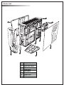
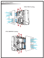
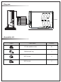
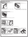
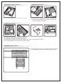
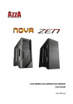
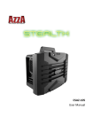
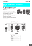
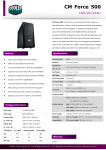
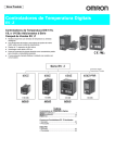
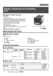
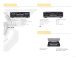
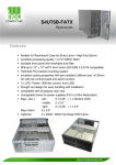
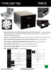
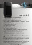
Z CSAZ-103
www.azzatek.com
Specifications
Model
Model Name
Z
Model Number
CSAZ-103
Specs
Type:
Mini-ITX Gaming Case
Color:
Black/Black(inside chassis)
Material:
0.6mm SECC
Side Panel Window:
Yes
With Power Supply:
No
CPU Cooler Compatibility:
up to 80mm
Motherboard Compatibility:
Mini ITX
Power Location
Front Bottom
Expansion
External 5.25" Drive Bays:
1
Internal 3.5" Drive Bays
2
Expansion Slots:
2
Front Ports:
1x USB 3.0, 2xUSB 2.0, HD Audio
Cooling System
120mm Fan:
1x120mm LED fan on side
Physical Spec
Dimensions(HxWxD)
13.5"x4.4"x17.3" (342mmx112mmx440mm HxWxD)
Weight
8lbs
Feature
Exceptional Cooling System
1x120mm LED fan on the side, intake the cool air in.
Support ATX power supply
Support Regular ATX power supply. No need to use
special kind TFX or 1U power supply.
Maximum Capacity water cooler Support up to 2x120mm water cooling radiators.
Support longest VGA card
Accommodate VGA card up to 11"
USB 3.0 Ready
1xUSB 3.0, 2xUSB 2.0
Easy install CPU cooler
A cut-off hole is prepared for installing CPU cooler with
ease, eliminating the need for prior removal of the
motherboard.
Parts List
1
2
7
9
8
3
5
6
4
1
2
3
4
5
6
7
8
9
Case
Left Side Panel
Right Side Panel
Stand
Front Panel
USB/Audio
Fan
Power Cord
PCI-E cable
Aircooling system
VGA/ PSU Cooling
CPU/ WATER Cooling
Diagram
POWER
RESET
RESET
342mm
USB 2.0(Black)
USB 3.0(Blue)
Mic
Audio
440mm
112mm
Assembly kit
Figure
Parts Name
Quantity
6*6 Hex washer screw
14
Motherboard tray
1
M3*5 screw
5
M2*4 screw
6
Installation Instruction
1.Remove the Front Cover
2.Remove the Side Cover
1.1 pull the front cover to remove as shown in the figure.
2.1 Remove the thumbscrews and pull the side covers
toward the back of the case, as shown in the figure.
3.Remove the Cooling System Bracket
3.1 Loosen the screws to remove the cooling system bracket.
4.PSU Installation
4.1 place the PSU into the chassis as shown figure.
4.2 connect the PSU cable, then tighten the screws to secure the PSU in place.
5.HDD Installation
5.1
5.2
5.3
5.4
Loosen the screws and remove the HDD tray.
Insert HDD into the tray, and fasten the screws as shown in the figure.
Put the HDD tray back, fasten the screws then.
Connect the HDD cable.
6.ODD (BD/DVD-ROM) Installation
6.1 Insert the ODD device, and fasten the screws.
7.Motherboard Installation
7.1 Install the I/O cover on the rear side of the chassis.
7.2 Place the motherboard into the slot as shown in the
figure, and fasten the screws.
8.VGA Card Installation
8.1
8.2
8.3
8.4
loosen the screw, and remove the VGA holder.
Install the VGA Card, and fasten the screws.
Remove the sticker(s) and paste the rubber pad(s) on the VGA holder if necessary.
Put VGA holder back, and connect the PCI-E cable.
9.Cooling System Installation
9.1 A Cooling system bracket is provided that accommodates
the installation of 120 / 240 mm water cooling system.
Maximum 240 mm
120 mm
Front Connector Installation Guide
Please refer to your motherboard user manual on the sections of “USB connector”And “audio connector”.
Please verify the pin definition before connecting the connectors to the motherboard
Remark:
1. USB and Audio connectors have foolproof design, can only be inserted in one direction
2. LED connectors have electrically positive and negative poles