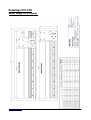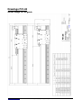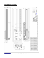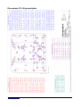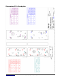
1
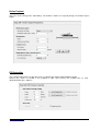
LinMot F01-37S and F01-48 Guides Version 1.67e www.LinMot-usa.com 0185-0026-E_1V67_IG_Linear_Guides_F01.odt 1/61 CAUTION LINMOT SLIDERS CONTAIN NEODYMIUM MAGNETS WHICH MAY DISTURB OR DAMAGE MAGNETIC DATA CARRIERS AND DELICATE ELECTRONIC EQUIPMENT MERELY BY COMING CLOSE TO THEM. WHEN HANDLING SLIDERS BE AWARE THAT, DUE THE STRONG MAGNETIC ATTRACTION, INJURY FROM FINGERS BEING PINCHED BETWEEN THE SLIDER AND NEARBY STEEL PARTS IS A VERY REAL POSSIBILITY IF CAUTION IS NOT EXERCISED. THE SLIDERS OF LINMOT® MOTORS CAN REACH TEMPERATURES WHICH MAY CAUSE BURNS UPON BEING TOUCHED. THE SLIDERS AND SHAFTS OF LINMOT® LINEAR-ROTARY MOTORS ARE FASTMOVING MACHINE PARTS. THE USER MUST TAKE ALL NECESSARY PRECAUTIONS TO PREVENT THEIR BEING TOUCHED (PROVIDE COVERS, PROTECTION AGAINST TOUCHING ETC.). The complete documentation including technical data, drawings and accessories can be downloaded from the download area on the web page www.LinMot-USA.com . CAD files and STEP files can be downloaded from the CAD download area on the web page www.LinMot-USA.com . www.LinMot-usa.com 0185-0026-E_1V67_IG_Linear_Guides_F01.odt 2/61 1 Inhaltsverzeichnis EXAMPLE LAYOUT............................................................................................................................................5 DESCRIPTION....................................................................................................................................................6 TECHNICAL DATA FOR F01-37 GUIDE............................................................................................................8 Dimensions and mass of F01-37S guides................................................................................................9 Moving masses 37S guides......................................................................................................................9 TECHNICAL DATA FOR F01-48 GUIDE..........................................................................................................10 Dimensions and mass of F01-48 guides.................................................................................................11 Moving masses of F01-48 guides...........................................................................................................11 DRIVE SETUP..................................................................................................................................................12 WIZARD LINMOT-TALK SOFTWARE.............................................................................................................12 Select the right stator and slider length..........................................................................................12 Define Payload...............................................................................................................................13 PID Controller.................................................................................................................................13 Homing............................................................................................................................................14 Full length of stroke........................................................................................................................15 ORDER INFORMATION FOR GUIDE F01-37S...............................................................................................16 1. Step: Select F01-37S guide...............................................................................................................16 2. Step: Select Slider..............................................................................................................................16 3. Step: Select type and quantity of Carriage-Kit...................................................................................17 4. Step: Select type and quantity of Stator.............................................................................................17 5. Step: Select Trailing chain kit or trailing chain (optional)....................................................................18 6. Step: Select Trailing chain cables (high-flex cable)............................................................................19 7. Step: External Sensor-Kit (optional)...................................................................................................20 8. Step: Magnetic strip (optional.............................................................................................................20 9. Step: Adapter plate for linear rotary motors (optional)........................................................................21 10. Step: Nuts for T-Slot (optional)..........................................................................................................21 Order example:.......................................................................................................................................22 ORDER INFORMATION FOR GUIDE F01-48.................................................................................................23 1. Step: Select F01-48 guide.................................................................................................................23 2. Step: Select Slider..............................................................................................................................23 3. Step: Select quantity of Carriage-Kit...................................................................................................24 4. Step: Select type and quantity of Stators and Flanges......................................................................24 5. Step: Select Trailing chain kit or trailing chain (optional)....................................................................25 6. Step: Select Trailing chain cables (high-flex cable)............................................................................26 7. Step: External Sensor-Kit (optional)...................................................................................................27 8. Step: Magnetic strip (optional.............................................................................................................27 9. Step: Adapter plate for linear rotary motors (optional)........................................................................28 10. Step: Nuts for T-Slot (optional)..........................................................................................................28 DIMENSIONS SEE DRAWINGS.....................................................................................................................28 GANTRY DESIGN.............................................................................................................................................29 Assembly of Gantry design.....................................................................................................................29 COMBINATION OF F01-48 AND F01-37S GUIDES........................................................................................30 Semi gantry design.................................................................................................................................30 MULTIPLE CARRIER DESIGN........................................................................................................................31 www.LinMot-usa.com 0185-0026-E_1V67_IG_Linear_Guides_F01.odt 3/61 MOUNTING INSTRUCTIONS...........................................................................................................................32 ASSEMBLING INSTRUCTIONS......................................................................................................................33 Direction of the motor cable ...................................................................................................................33 Assembly and disassembly of the motors and carriages ......................................................................33 Assembly of the slider.............................................................................................................................35 Assembly of the railway..........................................................................................................................35 Assembly of Trailing Chain Kit................................................................................................................36 Assembly of an external sensor-kit.........................................................................................................37 BEARING LOAD ON F01-37S GUIDES..........................................................................................................38 Static and dynamic bearing loads Fx und Fy..........................................................................................38 Calculation of the static load bearing Fx and Fy ...........................................................................38 Static and dynamic moment load Mxyz..................................................................................................39 ELECTRICAL CONNECTION OF TH PS01-37S STATORS ........................................................................40 Installation of the motor cable.................................................................................................................41 MAINTENANCE................................................................................................................................................42 Maintenance of Carriages.......................................................................................................................42 Relubrication of carriages...............................................................................................................42 Quantity of lubricant for carriages...................................................................................................42 Lubricant for carriages....................................................................................................................42 Maintenance of LinMot Motors................................................................................................................43 Storage / transport..................................................................................................................................44 CAUTION: HANDLING INSTRUCTIONS FOR SLIDERS...............................................................................45 DRAWINGS F01-37S........................................................................................................................................46 Stroke Range F01-37S guide ................................................................................................................46 Dimensions F01-37S guide.....................................................................................................................47 Dimensions F01-37S-AP ground plate...................................................................................................48 Dimensions F01-37S end plates.............................................................................................................49 Dimensions F01-37S T-slots...................................................................................................................50 Dimensions with H01-23x86 guide.........................................................................................................51 Dimensions with H01-37x166 guide.......................................................................................................52 Dimensions with PR01-52x40-R/37x120F-HP-C-80/-L..........................................................................53 Dimensions with PR01-52x60-R/37x120F-HP-C-100/-L........................................................................54 Dimensions with PR01-52x60-R/37x120F-HP-C-100-G........................................................................55 DRAWINGS F01-48..........................................................................................................................................56 Stroke Range F01-48 guide ...................................................................................................................56 Dimensions F01-48 guide ......................................................................................................................57 Dimensions F01-48 ground plate............................................................................................................58 Dimensions F01-48 end plate.................................................................................................................59 DECLARATION OF CONFORMITY CE-MARKING........................................................................................60 CONTACT ADDRESS:.....................................................................................................................................61 www.LinMot-usa.com 0185-0026-E_1V67_IG_Linear_Guides_F01.odt 4/61 Example Layout Figure 1: Gantry-Design with three F01-37S guides Figure 2: F01-37S guide with two independent motors on the same track www.LinMot-usa.com 0185-0026-E_1V67_IG_Linear_Guides_F01.odt 5/61 Description The LinMot F01-37S and F01-48 guides are moving stator applications with tubular linear motors. The mechanical design is based on a special aluminum profile on which a high precision profile rail guide is attached. Use of ball bearings in the carriages guarantee a reliable and smooth operation. The design of both guides is very similar but different in the dimensions. F-guides can be mounted together into a gantry design (Fig. 1) without any additional adapters. It is also possible to run more than one motor on the same guide (Fig. 2). There are two sizes of motors available for each size of F-guide; the PS01-37Sx60 offers highest velocity on a very short design while the PS0137Sx120 presents double the peak force with an additional 60mm length. The motors of the PS01-48 series offers a peek force up to 1000 N (250 lbf). Together with the H01 guides for the vertical axis (Fig. 3) and the linear rotary motors of the PR01-52 series (Fig. 4&5) the F-guides offer a powerful toolbox for any automation task. Figure 3: F01-37S Guide with mounted H01-23 guide for z-axis www.LinMot-usa.com 0185-0026-E_1V67_IG_Linear_Guides_F01.odt 6/61 Figure 4: F01-37S Guide with mounted linear rotary motor PR01-52 Figure 5: Gantry Design with mounted linear rotary motor PR01-52 www.LinMot-usa.com 0185-0026-E_1V67_IG_Linear_Guides_F01.odt 7/61 Technical data for F01-37 Guide value Note Static load rating C 15'400 N (3462 lbf) See chapter bearing load Dynamic load rating C0 8'400 N (1888 lbf) See chapter bearing load Static moment load Mx0 103 Nm (75.9 lb ft) See chapter bearing load My0 90 Nm (66.3 lb ft) See chapter bearing load Mz0 90 Nm (66.3 lb ft) See chapter bearing load Mx 56 Nm (41.3 lb ft) See chapter bearing load My 49 Nm (36.1 lb ft) See chapter bearing load Mz 49 Nm (36.1 lb ft) See chapter bearing load Max velocity vmax 5 m/s (196 in/s) Max acceleration amax Dynamic moment load 75 m/s 2 Depending on motor (2952 in/s ) 2 Depending on motor Stator PS01-37Sx60 Peak Force Fpeak 122 N (27.4 lbf) Continuous Force Fcont 20 N (4.5 lbf) Max phase current @ 72VDC Imax 12 A m lin tot 1100 g (2.42 lb) Moving mass total Repeatability without external Sensor +/- 0.05 mm (+/- 0.002 in) +/- 0.01 mm (+/- 0.0004 in) Repeatability with external Sensor Fr 7 N (1.6 lbf) Peak Force Fpeak 255 N (57.3 lbf) Continuous Force Fcont 35 (7.8 lbf) Max phase current @ 72VDC Imax 15 A m lin tot 1470 g (3.24 lb) Friction (estimation) Stator, carriage, adapter plate With external sensor Dependent on application Stator PS01-37Sx120 Moving mass total Repeatability without external Sensor +/- 0.05 mm (+/- 0.002 in) Repeatability with external Sensor +/- 0.01 mm (+/- 0.0004 in) Friction (estimation) Fr 7 N (1.6 lbf) Stator, carriage, adapter plate With external sensor Dependent on application To calculate the motor specific application data we recommend to use the sizing tool LinMot Designer. (see Download sector on www.LinMot.com ) www.LinMot-usa.com 0185-0026-E_1V67_IG_Linear_Guides_F01.odt 8/61 Dimensions and mass of F01-37S guides Description Part-No Length total Mass F01-37Sx300 0150-5453 330 mm (13.0 in) 3430 g (7.57 Ib) F01-37Sx400 0150-5449 430 mm (16.9 in) 4310 g (9.5 Ib) F01-37Sx500 0150-5450 530 mm (20.9 in) 5220 g (11.51 Ib) F01-37Sx600 0150-5424 630 mm (24.8 in) 6100 g (13.45 Ib) F01-37Sx800 0150-5425 830 mm (32,7 in) 7860 g (17.33 Ib) F01-37Sx1000 0150-5426 1030 mm (40.6 in) 9640 g (21.25 Ib) F01-37Sx1200 0150-5427 1230 mm ( 48.4 in) 11400 g (25.13 ib) F01-37Sx1400 0150-5428 1430 mm (56.3 in) 13200 g (29.10 Ib) F01-37Sx1600 0150-5429 1630 mm (64.2 in) 14930 g (32.92 Ib) F01-37Sx2000 0150-5430 2030 mm (79.9 in) 18490 g (40.76 Ib) Mass including end-plates, profile rail and slider (without stator and adapter plate) Moving masses 37S guides Stator PS01-37Sx60-HP-N-AGI with carrier kit F01-37S/FWK: carrier kit F01-37S/FWK-F: 1100 g (2.42 Ib) 1290 g (2.84 Ib) Stator PS01-37Sx120-HP-N-AGI with carrier kit F01-37S/FWK: carrier kit F01-37S/FWK-F: 1470 g (3.24 Ib) 1660 g (3.66 Ib) www.LinMot-usa.com 0185-0026-E_1V67_IG_Linear_Guides_F01.odt 9/61 Technical data for F01-48 Guide value Note Static load rating C 30'800 N (6924 lbf) See chapter bearing load Dynamic load rating C0 16'800 N (3776 lbf) See chapter bearing load Static moment load Mx0 206 Nm (151.8 lb ft) See chapter bearing load My0 180 Nm (132.6 lb ft) See chapter bearing load Mz0 180 Nm (132.6 lb ft) See chapter bearing load Mx 112 Nm (82.6 lb ft) See chapter bearing load My 98 Nm (72.2 lb ft) See chapter bearing load Mz 98 Nm (72.2 lb ft) See chapter bearing load Max velocity vmax 3 m/s (118 in/s) Max acceleration amax Dynamic moment load 50 m/s 2 Depending on motor (1968 in/s ) 2 Depending on motor Stator PS01-48X240F-C Peak Force Fpeak 550 N (123.6 lbf) Continuous Force Fcont 145 N (32.6 lbf) Max phase current @ 72VDC Imax 26 A m lin tot 4900 g (10.8 Ib) Moving mass total Repeatability without external Sensor +/- 0.05 mm (+/- 0.002 in) +/- 0.01 mm (+/- 0.0004 in) Repeatability with external Sensor Fr 30 N (6.7 lbf) Peak Force Fpeak 1024 N (230.1 lbf) Continuous Force Fcont 203 N (45.7 lbf) Max phase current @ 72VDC Imax 32 A m lin tot 6250 g (13.8 Ib) Friction (estimation) Stator, carriage, adapter plate With external sensor Dependent on application Stator PS01-48X360F-C Moving mass total Stator, carriage, adapter plate Repeatability without external Sensor +/- 0.05 mm (+/- 0.002 in) Repeatability with external Sensor +/- 0.01 mm (+/- 0.0004 in) With external sensor 34 N (7.6 lbf) Dependent on application Friction (estimation) Fr To calculate the motor specific application data we recommend to use the sizing tool LinMot Designer. (see Download sector on www.LinMot.com ) www.LinMot-usa.com 0185-0026-E_1V67_IG_Linear_Guides_F01.odt 10/61 Dimensions and mass of F01-48 guides Description Part-No Length total Mass F01-48x500 0150-5469 540 mm (21.3 in) 6.93 kg (15.27 lb) F01-48x620 0150-5470 660 mm (26.0 in) 8.19 kg (18.04 lb) F01-48x800 0150-5471 840 mm (33.1 in) 10.19 kg (22.46 lb) F01-48x1010 0150-5472 1050 mm (41.3 in) 12.45 kg (27.44 lb) F01-48x1220 0150-5473 1260 mm (49,6 in) 14.70 kg (32.42 lb) F01-48x1400 0150-5474 1440 mm (56.7 in) 16.71 kg (36.84 lb) F01-48x1610 0150-5475 1650 mm ( 65,0.4 in) 18.97 kg (41.81 lb) F01-48x1820 0150-5476 1860 mm (73.2 in) 21.23 kg (46.81 lb) F01-48x2000 0150-5477 2040 mm (80.3 in) 23.18 kg (51.09 lb) F01-48x2210 0150-5478 2250 mm (88,6 in) 25.44 kg (56.09 lb) F01-48x2450 0150-5478 2490 mm 28.03 kg (61.79 lb) (98.0 in) Mass including end-plates, profile rail and slider (without stator and adapter plate) Moving masses of F01-48 guides Stator PS01-48x240F-C , Flange PF03-48x226 and carrier kit F01-48/FWK-F: 4.90 kg (10.8 Ib) Stator PS01-48x360F-C, Flange PF03-48x346 and carrier kit F01-48/FWK-F: 6.25 kg (13.8 Ib) www.LinMot-usa.com 0185-0026-E_1V67_IG_Linear_Guides_F01.odt 11/61 Drive Setup The best way to setup a F-Guide together with a LinMot drive is to follow the wizard of the LinMot-Talk software. Detailed information about this wizard can be found in the manuals about the drives. Please note the following screen shots of the wizard which may help to answer some questions Wizard LinMot-Talk Software Select the right stator and slider length (Note: F01-37Sx1600-F relates to a slider PL01-20x1600/1540-HP stator selection: see label on the stator) Select 'regular' for Slider mounting direction (comment: in this kind of application the slider direction is not important). www.LinMot-usa.com 0185-0026-E_1V67_IG_Linear_Guides_F01.odt 12/61 Define Payload The mass of the carriage-kit is about 465 g. The friction is about 7 N. In gantry design, the friction may be higher. PID Controller See recommended values to start (the values are higher than normal motor without F-guide) Increase the values if needed. If the payload is high, then increase the D-Filter time as well. (Default D-Filter time = 400 us). www.LinMot-usa.com 0185-0026-E_1V67_IG_Linear_Guides_F01.odt 13/61 Homing Measure the distance B, which is the distance between the carriage and the end-plate, if the carriage is at the other end of the guide. www.LinMot-usa.com 0185-0026-E_1V67_IG_Linear_Guides_F01.odt 14/61 Full length of stroke To use the full length of the mechanical stroke on a F01-37S guide it is necessary to switch off the 'Maximal Position' error. Or change the minimal and maximal position www.LinMot-usa.com 0185-0026-E_1V67_IG_Linear_Guides_F01.odt 15/61 Order Information for Guide F01-37S The guides will be delivered pre-assembled. See section 'Assembling of components' if additional stators or parts must be installed later. Go step by step though the following order procedure: 1. Step: Select F01-37S guide Description Part-No F01-37Sx300 0150-5453 F01-37Sx400 Length total Stroke w. PS01-37Sx60* Stroke w. PS01-37Sx120* 330 mm 200 mm (7.8'') 140 mm (5.5'') 0150-5449 430 mm 300 mm (11.8'') 240 mm (9.4'') F01-37Sx500 0150-5450 530 mm 400 mm (15.7'') 340 mm (13.3'') F01-37Sx600 0150-5424 630 mm 500 mm (19.6'') 440 mm (17.3'') F01-37Sx800 0150-5425 830 mm 700 mm (27.5'') 640 mm (25.1'') F01-37Sx1000 0150-5426 1030 mm 900 mm (35.4'') 840 mm (33'') F01-37Sx1200 0150-5427 1230 mm 1100 mm (43.3'') 1040 mm (40.9'') F01-37Sx1400-F 0150-5428 1430 mm 1300 mm (51.1'') 1240 mm (48.8'') F01-37Sx1600-F 0150-5429 1630 mm 1500 mm (59'') 1440 mm (56.6'') F01-37Sx2000-F 0150-5430 2030 mm 1900 mm (74.7'') 1840 mm (72.4'') *Stroke tolerance: +0 mm/ -5 mm Guide including end-plates and profile rail 2. Step: Select Slider Description Part-No For Guide PL01-20x300/240-HP 0150-1506 F01-37Sx300 PL01-20x400/340-HP 0150-1508 F01-37Sx400 PL01-20x500/440-HP 0150-1509 F01-37Sx500 PL01-20x600/540-HP 0150-1510 F01-37Sx600 PL01-20x800/740-HP 0150-1512 F01-37Sx800 PL01-20x1000/940-HP 0150-1514 F01-37Sx1000 PL01-20x1200/1140-HP 0150-1515 F01-37Sx1200 PL01-20x1400/1340-HP 0150-1516 F01-37Sx1400-F PL01-20x1600/1540-HP 0150-1517 F01-37Sx1600-F PL01-20x2000/1940-HP 0150-1543 F01-37Sx2000-F One slider is necessary for each guide. www.LinMot-usa.com 0185-0026-E_1V67_IG_Linear_Guides_F01.odt 16/61 3. Step: Select type and quantity of Carriage-Kit Description Part-No Description F01-37S/FWK 0150-5480 Carriage and ground plate for guides <1400 mm F01-37S/FWK-F 0150-5481 Carriage and ground plate for guides >= 1400 mm It is possible to run more than one carriage on one guide. Kit includes carriage, adapter plate and all screws to mount stator and carriage. Note: F01-37S guides equal or longer than 1400 mm need F01-37S/FWK-F carriage kits. The ground plate of the F01-37S/FWK-F is 7 mm thicker than the ground plate of the F01-37S/FWK. That means all mounted parts are moved by 7 mm. See dimensions in brackets on the drawings. Spare part: Carriage (from SKF) without adapter plate: LLTHC 15 U-T2 P5 Part-No 0150-5265 4. Step: Select type and quantity of Stator Description Part-No PS01-37Sx60-HP-N-AGI 0150-2549 37 series HP stator with N connector (IP50) PS01-37Sx120F-HP-N-AGI 0150-2550 37 series HP stator with N connector (IP50) It is possible to run more than one stator on one guide. Each stator needs its own carriage-kit. If different stators are ordered, it is necessary to note the assembling sequence of the stators (from left to right) on the guide, viewing angle from the site with the trailing chain (see pictures Design 'cable to the left' or 'cable to the right'. (e.g. 3 stators in the sequence (from left to right): PS01-37Sx60 / PS01-37Sx60 / PS01-37Sx120 ) Design: ' cable to the left' Design: 'cable to the right' (default) If not mentioned differently, F-guides will be assembled 'cable to the right'. www.LinMot-usa.com 0185-0026-E_1V67_IG_Linear_Guides_F01.odt 17/61 5. Step: Select Trailing chain kit or trailing chain (optional) 5.1 Trailing chain kit Description Part-No For Guide Length of trailing chain F01-TC300 0150-5457 F01-37Sx300 Ca 200 mm F01-TC400 0150-5456 F01-37Sx400 Ca 300 mm F01-TC500 0150-5455 F01-37Sx500 Ca 400 mm F01-TC600 0150-5439 F01-37Sx600 Ca 500 mm F01-TC800 0150-5440 F01-37Sx800 Ca 600 mm F01-TC1000 0150-5441 F01-37Sx1000 Ca 700 mm F01-TC1200 0150-5442 F01-37Sx1200 Ca 800 mm F01-TC1400 0150-5443 F01-37Sx1400-F Ca 900 mm F01-TC1600 0150-5444 F01-37Sx1600-F Ca 1000 mm F01-TC2000 0150-5445 F01-37Sx2000-F Ca 1200 mm Includes trailing chain and brackets to mount the trailing chain to the stator and the guide. (The kit can not be used for multiple carriage applications). 5.2 Trailing chain Description Part-No For Guide Length of trailing chain F01h-KS300 0160-0983 F01-37Sx300 Ca 200 mm F01h-KS400 0160-0981 F01-37Sx400 Ca 300 mm F01h-KS500 0160-0982 F01-37Sx500 Ca 400 mm F01h-KS600 0160-0971 F01-37Sx600 Ca 500 mm F01h-KS800 0160-0972 F01-37Sx800 Ca 600 mm F01h-KS1000 0160-0973 F01-37Sx1000 Ca 700 mm F01h-KS1200 0160-0974 F01-37Sx1200 Ca 800 mm F01h-KS1400 0160-0975 F01-37Sx1400-F Ca 900 mm F01h-KS1600 0160-0976 F01-37Sx1600-F Ca 1000 mm F01h-KS2000 0160-0977 F01-37Sx2000-F Ca 1200 mm Only trailing chain without any brackets www.LinMot-usa.com 0185-0026-E_1V67_IG_Linear_Guides_F01.odt 18/61 6. Step: Select Trailing chain cables (high-flex cable) Description Part-No Description For Motor KS03-R/N-1.5 0150-3563 Trailing chain cable 1.5 m with R/N-connector PS01-37Sx60 or PS01-37Sx120 KS03-R/N-2 0150-3564 Trailing chain cable 2 m with R/N-connector PS01-37Sx60 or PS01-37Sx120 KS03-R/N-3 0150-3565 Trailing chain cable 3 m with R/N-connector PS01-37Sx60 or PS01-37Sx120 KS03-R/R-1.5 0150-3566 Trailing chain cable 1.5 m with R/R-connector PR01-52x40-R/37x120F-... KS03-R/R-2 0150-3567 Trailing chain cable 2 m with R/R-connector PR01-52x40-R/37x120F-... KS03-R/R-3 0150-3568 Trailing chain cable 3 m with R/R-connector PR01-52x40-R/37x120F-... KS03-C/C-1.5 0150-3569 Trailing chain cable 1.5 m with C/C-connector PR01-52x40-R/37x120F-.. KS03-C/C-2 0150-3570 Trailing chain cable 2 m with C/C-connector PR01-52x40-R/37x120F-.. KS03-C/C-3 0150-3571 Trailing chain cable 3 m with C/C-connector PR01-52x40-R/37x120F-.. The KS03 trailing chain cable should be as short as possible. Use an extension cable for the connection between the trailing chain cable and the drive. • • • PS01-37S stators which are built into the F01-37S guides need KS03-R/N-.. cables The rotary part of the PR01-52x40-R/37x120F-..motors or the PS01-23x …-R stators need KS03R/R-... cables The lineary part of the PR01-52x40-R/37x120F-..motors or PS01-37x … -C stators need KS03C/C-... cables www.LinMot-usa.com 0185-0026-E_1V67_IG_Linear_Guides_F01.odt 19/61 7. Step: External Sensor-Kit (optional) Description Part-No F01-37S-SK 0150-5446 Identical for all guides, cable length 2m The external sensor kit includes sensor MS01-1/D Part- No 0150-1840, sensor adapter plate and mounting screws. The magnetic strip must be ordered separately. 8. Step: Magnetic strip (optional Description Part-No For Guide F01-MB300 0150-5454 F01-37Sx300 F01-MB400 0150-5451 F01-37Sx400 F01-MB500 0150-5452 F01-37Sx500 F01-MB600 0150-5431 F01-37Sx600 F01-MB800 0150-5432 F01-37Sx800 F01-MB1000 0150-5433 F01-37Sx1000 F01-MB1200 0150-5434 F01-37Sx1200 F01-MB1400 0150-5435 F01-37Sx1400-F F01-MB1600 0150-5436 F01-37Sx1600-F F01-MB2000 0150-5437 F01-37Sx2000-F Only one magnetic strip is needed for several motors with external position sensor kits to run on one guide. www.LinMot-usa.com 0185-0026-E_1V67_IG_Linear_Guides_F01.odt 20/61 9. Step: Adapter plate for linear rotary motors (optional) Description Part-No For linear rotary motors F01k-PR01-52 0160-2536 PR01-52x40-R/37x120F-HP-C-80 (-L) PR01-52x60-R/37x120F-HP-C-100 (-L) F01k-PR01-52x60 0160-2657 F01k-PR01-84* 0160-2594 PR01-52x60-R/37x120F-HP-C-100 (-L) PR01-52x60-R/37x120F-HP-C-150 (-L) PR01-84x80-C/48x240F-C100 (-L) (-G0x) PR01-84x80-C/48x360F-C100 (-L) (-G0x) The adapter plats must be mounted to a F01-37S/FWK or F01-37S/FWK-F carriage kit. 10. Step: Nuts for T-Slot (optional) Description Part-No Nut N8 / M4 0150-2189 Nut for 8 mm slots of F01 guides with M4 thread Nut N8 / M6 0150-2558 Dimensions see drawings Nut for 8 mm slots of F01 guides with M6 thread www.LinMot-usa.com 0185-0026-E_1V67_IG_Linear_Guides_F01.odt 21/61 Order example: Example 1: F01-37S guide shorter than 1400 mm pcs Description Part-No comment 1 F01-37Sx800 0150-5425 F01-37S guide 800 mm 1 PL01-20x800/740-HP 0150-1512 Slider 1 F01-37S/FWK 0150-5480 Carriage kit (Guide <1400 mm) 1 PS01-37Sx120F-HP-N-AGI 0150-2550 Stator (linear motor) 1 F01-TC800 0150-5440 Trailing chain kit 1 KS03-R/N-2 0150-3564 Trailing chain cable 2 m Example 2: F01-37S guide longer than 1400 mm with optional external sensor pcs Description Part-No comment 1 F01-37Sx1600-F 0150-5429 F01-37S guide 1600 mm 1 PL01-20x1600/1440-HP 0150-1517 Slider 1 F01-37S/FWK-F 0150-5481 Carriage kit (guide >= 1400 mm) 1 PS01-37Sx60-HP-N-AGI 0150-1549 Stator (linear motor) “Design: cable to the left” 1 F01-TC1600 0150-5444 Trailing chain kit 1 KS03-R/N-2 0150-3564 Trailing chain cable 2 m 1 F01-37S-SK 0150-5446 External Sensor kit, cable length 2m 1 F01-MB1600 0150-5436 Magnetic Strip for F01-37Sx1600 Example 3: F01-37S guide longer than 1400 mm with 3 moving stators pcs Description Part-No comment 1 F01-37Sx1600-F 0150-5429 F01-37S guide 1600 mm 1 PL01-20x1600/1440-HP 0150-1517 Slider 3 F01-37S/FWK-F 0150-5481 Carriage kit (guide >= 1400 mm) 2 PS01-37Sx120F-HP-N-AGI 0150-2550 Stator (linear motor) 1 PS01-37Sx60-HP-N-AGI 0150-1549 Stator (linear motor) 3 KS03-R/N-2 0150-3564 Trailing chain cable 2 m 4 Nut N8 / M6 0150-2558 Nuts for T-Slot to mount the F-Guide Sequence of stators: PS01-37Sx120F / PS01-37Sx120F /PS01-37Sx60F www.LinMot-usa.com 0185-0026-E_1V67_IG_Linear_Guides_F01.odt 22/61 Order Information for Guide F01-48 The guides will be delivered pre-assembled. See section 'Assembling of components' if additional stators or parts must be installed later. Go step by step though the following order procedure: 1. Step: Select F01-48 guide Description Part-No Length total Stroke w.ith PS01-48x240F-C Stroke w.ith PS01-48x360F-C F01-48x500 0150-5469 540 mm (21.3 in) 200 mm (7.8'') 80 mm (3.1'') F01-48x620 0150-5470 660 mm (26.0 in) 320 mm (12.5'') 200 mm (7.8'') F01-48x800 0150-5471 840 mm (33.1 in) 500 mm (19.6'') 380 mm (14.9'') F01-48x1010 0150-5472 1050 mm (41.3 in) 710 mm (27.9'') 590 mm (23.2'') F01-48x1220 0150-5473 1260 mm (49,6 in) 920 mm (36.2') 800 mm (31.4'') F01-48x1400 0150-5474 1440 mm (56.7 in) 1100 mm (43.3'') 980 mm (38.5'') F01-48x1610 0150-5475 1650 mm ( 65,0.4 in) 1310 mm (51.5'') 1190 mm (46.8'') F01-48x1820 0150-5476 1860 mm (73.2 in) 1520 mm (59.8'') 1400 mm (55.1'') F01-48x2000 0150-5477 2040 mm (80.3 in) 1700 mm (66.9'') 1580 mm (62.2'') F01-48x2210 0150-5478 2250 mm (88,6 in) 1960 mm (77.1'') Not available F01-48x2450 0150-5478 2490 mm 2150 mm (84.6'') Not available (98.0 in) 2. Step: Select Slider Description Part-No For Guide PL01-28x500/420 0150-1382 F01-48x500 PL01-28x620/540 0150-1383 F01-48x620 PL01-28x800/720 0150-1385 F01-48x800 PL01-28x1010/930 0150-1387 F01-48x1010 PL01-28x1220/1140 0150-1388 F01-48x1220 PL01-28x1400/1320 0150-1389 F01-48x1400 PL01-28x1610/1530 0150-1390 F01-48x1610 PL01-28x1820/1740 0150-1395 F01-48x1820 PL01-28x2000/1920 0150-1396 F01-48x2000 PL01-28x2210/2130 0150-1397 F01-48x2210 PL01-28x2450/2370 0150-1398 F01-48x2450 One slider is necessary for each guide. www.LinMot-usa.com 0185-0026-E_1V67_IG_Linear_Guides_F01.odt 23/61 3. Step: Select quantity of Carriage-Kit Description Part-No Description F01-48/FWK-F 0150-5488 Kit inlucedes 2 carriages and ground plate It is possible to run more than one carriage on one guide. Kit includes 2 carriages, ground plate and all screws to mount stator, flange and carriage. Spare part: Carriage (from SKF) without ground plate: LLTHC 15 U-T2 P5 Part-No 0150-5265 (2 pcs necessary) 4. Step: Select type and quantity of Stators and Flanges Description Part-No PS01-48x240F-C PF03-48x226 0150-1220 0150-5489 48 series HP stator with C connector Flange for PS01-48x240F-C and F01-48 Guide PS01-48x360F-C PF03-48x346 0150-1269 0150-5490 48 series HP stator with C connector Flange for PS01-48x360F-C and F01-48 Guide Each stator needs a flange to be mounted on an a ground plate F01-48/FWK-F. It is possible to run more than one stator on one guide. Each stator needs its own carriage-kit. If different stators are ordered, it is necessary to note the assembling sequence of the stators (from left to right) on the guide, viewing angle from the site with the trailing chain (see pictures Design 'cable to the left' or 'cable to the right'. (e.g. 3 stators in the sequence (from left to right): PS01-48x240F / PS01-48x240F / PS01-48x360F ) Design: ' cable to the left' Design: 'cable to the right' (default) If not mentioned differently, F-guides will be assembled 'cable to the right'. www.LinMot-usa.com 0185-0026-E_1V67_IG_Linear_Guides_F01.odt 24/61 5. Step: Select Trailing chain kit or trailing chain (optional) 5.1 Trailing chain kit Description Part-No For Guide Length of trailing chain F01-TC500 0150-5455 F01-48x500 Ca 400 mm F01-TC600 0150-5439 F01-48x620 Ca 500 mm F01-TC800 0150-5440 F01-48x800 Ca 600 mm F01-TC1000 0150-5441 F01-48x1010 Ca 700 mm F01-TC1200 0150-5442 F01-48x1220 Ca 800 mm F01-TC1400 0150-5443 F01-48x1400 Ca 900 mm F01-TC1600 0150-5444 F01-48x1610 Ca 1000 mm F01-TC1800 0150-5492 F01-48x1820 Ca 1100 mm F01-TC2000 0150-5445 F01-48x2000 Ca 1200 mm F01-TC2200 0150-5493 F01-48x2210 Ca 1300 mm F01-TC2400 0150-5494 F01-48x2450 Ca 1400 mm Includes trailing chain and brackets to mount the trailing chain to the stator and the guide. (The kit can not be used for multiple carriage applications). 5.2 Trailing chain Description Part-No For Guide Length of trailing chain F01h-KS500 0160-0982 F01-48x500 Ca 400 mm F01h-KS600 0160-0971 F01-48x620 Ca 500 mm F01h-KS800 0160-0972 F01-48x800 Ca 600 mm F01h-KS1000 0160-0973 F01-48x1010 Ca 700 mm F01h-KS1200 0160-0974 F01-48x1220 Ca 800 mm F01h-KS1400 0160-0975 F01-48x1400 Ca 900 mm F01h-KS1600 0160-0976 F01-48x1610 Ca 1000 mm F01h-KS1800 0160-1011 F01-48x1820 Ca 1100 mm F01h-KS2000 0160-0977 F01-48x2000 Ca 1200 mm F01h-KS2200 0160-1012 F01-48x2210 Ca 1300 mm F01h-KS2400 0160-1013 F01-48x2450 Ca 1400 mm Only trailing chain without any brackets www.LinMot-usa.com 0185-0026-E_1V67_IG_Linear_Guides_F01.odt 25/61 6. Step: Select Trailing chain cables (high-flex cable) PS01-48x240F-C and PS01-48x360F-C should be used with KS10 trailing chain (high flex) cables. Description Part-No Description For Drives KS10-C/C-2 0150-1816 Trailing chain cable 2 m with C/C-connector Extension cable KS10-C/C-4 0150-1817 Trailing chain cable 4 m with C/C-connector Extension cable KS10-W/C-4 0150-1807 Trailing chain cable W/C, 4 m E1100, E1200 series KS10-W/C-5 0150-1860 Trailing chain cable W/C, 5 m E1100, E1200 series KS10-W/C-6 0150-1858 Trailing chain cable W/C, 6 m E1100, E1200 series KS10-W/C-8 0150-1808 Trailing chain cable W/C, 8 m E1100, E1200 series KS10-Y/C-4 0150-2439 Trailing chain cable Y/C, 4 m C1100, C1200 series KS10-Y/C-6 0150-2440 Trailing chain cable Y/C, 4 m C1100, C1200 series KS10-Y/C-8 0150-2441 Trailing chain cable Y/C, 8 m C1100, C1200 series See LinMot databook or e-catalogue for more cable options. www.LinMot-usa.com 0185-0026-E_1V67_IG_Linear_Guides_F01.odt 26/61 7. Step: External Sensor-Kit (optional) Description Part-No F01-37S-SK 0150-5446 Identical for all guides, cable length 2m The external sensor kit includes sensor MS01-1/D Part- No 0150-1840, sensor adapter plate and mounting screws. The magnetic strip must be ordered separately. 8. Step: Magnetic strip (optional . Description Part-No For Guide F01-MB500 0150-5452 F01-48x500 F01-MB620 0150-5461 F01-48x620 F01-MB800 0150-5432 F01-48x800 F01-MB1010 0150-5462 F01-48x1010 F01-MB1220 0150-5463 F01-48x1220 F01-MB1400 0150-5465 F01-48x1400 F01-MB1610 0150-5464 F01-48x1610 F01-MB1820 0150-5465 F01-48x1820 F01-MB2000 0150-5437 F01-48x2000 F01-MB2210 0150-5467 F01-48x2210 F01-MB2450 0150-5468 F01-48x2450 www.LinMot-usa.com 0185-0026-E_1V67_IG_Linear_Guides_F01.odt 27/61 9. Step: Adapter plate for linear rotary motors (optional) Description Part-No For linear rotary motors F01k-PR01-52 0160-2536 PR01-52x40-R/37x120F-HP-C-80 (-L) PR01-52x60-R/37x120F-HP-C-100 (-L) F01k-PR01-52x60 0160-2657 F01k-PR01-84 0160-2594 PR01-52x60-R/37x120F-HP-C-100 (-L) PR01-52x60-R/37x120F-HP-C-150 (-L) PR01-84x80-C/48x240F-C100 (-L) (-G0x) PR01-84x80-C/48x360F-C100 (-L) (-G0x) The adapter plats must be mounted to a F01-48/FWK-F carriage kit. Note: H- and B-guides can directly be mounted to the F01-48/FWK-F carriage kit. 10. Step: Nuts for T-Slot (optional) Description Part-No Nut N8 / M4 0150-2189 Nut for 8 mm slots of F01 guides with M4 thread Nut N8 / M6 0150-2558 Dimensions see drawings Nut for 8 mm slots of F01 guides with M6 thread www.LinMot-usa.com 0185-0026-E_1V67_IG_Linear_Guides_F01.odt 28/61 Gantry Design If requested, Gantry Designs will be delivered pre-assembled. Please note direction of the cables Design “left” (cable to the left) Design “right” (cable to the right): Assembly of Gantry design 1. Pins 5x20 mm (2 pcs on both side) 2. Screws M6x30 (4 pcs on both side) www.LinMot-usa.com 0185-0026-E_1V67_IG_Linear_Guides_F01.odt 29/61 Combination of F01-48 and F01-37S guides F01-37 guides can directly be mounted to the bigger F01-48 guides. It is also possible to realize semi gantry constructions as shown below. Semi gantry design Semi gantry designs are very cost effective solutions. It is possible to realize a semi gantry without an additional X-guide as long as the F01-37 guide is short (max 400 mm) and some vibrations are acceptable. However in high performance applications, heavy load conditions, or long Y-axis strokes an additional Xguide must be considered. Semi gantry design: F01-48 guide (X-axis), short F01-37 guide (y-axis), H01-23 guide (Z-axle) Semi gantry design: F01-48 guide (X-axis), F01-37S guide (Y-Axis) with additional X-guide to eliminate vibrations, H01-23 guide (Z-axis) www.LinMot-usa.com 0185-0026-E_1V67_IG_Linear_Guides_F01.odt 30/61 Multiple carrier design The picture shows one possibility to arrange the trailing chains for a multiple carrier design. Because of the huge number of design variations the adapters must be produced by the customer. www.LinMot-usa.com 0185-0026-E_1V67_IG_Linear_Guides_F01.odt 31/61 Mounting instructions Mounting by side plates Mounting 'from the bottom' with nuts and T-slots. Orientation: “Slider to the top” Note: F01-37S guides, which are 1400 mm or longer, must be mounted with the “slider to the top”, as shown in the drawings. Shorter guides can be mounted in every direction. In this case the user has to mount the trailing chain cables corresponding. www.LinMot-usa.com 0185-0026-E_1V67_IG_Linear_Guides_F01.odt 32/61 Assembling Instructions F01-37 guides will normally be delivered completely assembled. In case of replacements or if additional carriages/motors should be installed the following installation guides must be considered. Use always threadlocker. Direction of the motor cable According to the application and trailing chain installation of the motor cable, the outlet must be selected. See installation guide of the short stators PS01-37Sx... for details. Assembly and disassembly of the motors and carriages Disassemble the end plate from the side where the slider is in the loose bearing (not fixed by the screw). Support the slider with non-iron parts so that it can not fall into the guide and remove the end plate. www.LinMot-usa.com 0185-0026-E_1V67_IG_Linear_Guides_F01.odt 33/61 1. Move the carriage (3) carefully on the profile rail. Mount adapter plate (2) with screws 5 (M4x8) to the carriage. Make sure that the adapter plate (2) is aligned to the profile rail (use 90° bracket) ! Now tighten screws 5. Mount stator (1) with screws 4 (M5x45) to the adapter plate (2). (The direction of the stator may depend on the needs of the application). 2. Assemble end plate with screws M6x25 3. Loosen screws 4 to align the stator. Move the carriage unit to the loosen bearing side of the guide. Then tighten screws 4 . 4. Move carriage unit to the side with the fixed bearing and loose screws 4 once again if the carriage shows heavy friction. Re-tighten screws 4. 5. Move the carriage unit to the side with the loose bearing, If the carriage shows heavy friction then loose screws from the end plate and tighten screws again. Loosen screws 4 to align the stator. Move the carriage unit to the loose bearing side of the guide. Then tighten screws 4 6. Move the carriage unit to the side with the fixed bearing, If the carriage shows still heavy friction then loosen the M8 screw of the slider and tight it again. Then start alignment process as written before again (steps 3 to 6). ) www.LinMot-usa.com 0185-0026-E_1V67_IG_Linear_Guides_F01.odt 34/61 Assembly of the slider Select the end of the slider without the notches and fasten slider with screw M8x35 to the end plate. Mount spherical washers on both side of the end plate. Use conical washer on the side of the slider. Assembly of the railway Use M4x16 screws and nuts to mount the railway to the profile. Align the railway with the profile. Every position for the screws must be used.The end plates are mounded with M6x25 screws. www.LinMot-usa.com 0185-0026-E_1V67_IG_Linear_Guides_F01.odt 35/61 Assembly of Trailing Chain Kit Mount the L-profile with M4x10 screws and nuts into the middle or lower slot of the guide depending on the bend radius of the high flex cables. Mount the adapter to the stator with 2 screws M4x5. Fix the trailing chain to the L-profile and the adapter with 4 screws M3x6. Trailing chains are located in parallel (side by side) for multiple motor applications. Adapters and L-profiles for the chains are depending on the application and must be designed by the user. www.LinMot-usa.com 0185-0026-E_1V67_IG_Linear_Guides_F01.odt 36/61 Assembly of an external sensor-kit 1.) Clean slot on guide profile 2.) Stick magnetic strip with cover into the slot 3.) Screw sensor with 2 pcs M3x12 on the adapter plate and adjust distance according to the installation guide for the external sensor. 4.) Install adapter with sensor to the backside of the adapter plate (2 pcs M2.5x8) . Secure sensor cable with bracket to the adapter plate (M3x6). www.LinMot-usa.com 0185-0026-E_1V67_IG_Linear_Guides_F01.odt 37/61 Bearing load on F01-37S guides Static and dynamic bearing loads Fx und Fy F01-37S guide SKF profile rail guide: LLT Size 15 profil rail, carriage LLTHC 15 U-T2 P5 See SKF Manual 'Profile rail guides LLT' ( www. SKF.com, document: 12942_1_EN_LLT_2013.pdf) for additional information about lifetime and maintenance. (LLT Size 15 profil rail, carriage LLTHC 15 UT2 P5) Load capacity static: Load capacity dynamic: C0:= 15,400 N C := 8,400 N The static and dynamic load bearing will normally not be calculated because a reasonable application will be limited by the motor performance and not the load bearing. To calculate the application data we recommend to use the analyzing program LinMot Desiger (see Downloads sector on www.LinMot.com ) If the application shows massive static forces, e.g. if a press is punching on parts which are moved on the guide, then the load bearing must be evaluated carefully. Calculation of the static load bearing Fx and Fy To calculate the static bearing load you need the factor fd for the load condition, the desired static safety factor s0, and the resulting force Fres. The static load of the F01-37S guide is: C0 := 15,400 N www.LinMot-usa.com 0185-0026-E_1V67_IG_Linear_Guides_F01.odt 38/61 Load condition fd Max velocity Max acceleration vmax< 2 m/s : vmax> 2 m/s: fd=1 .....1.5 fd=1.5 ....3 static safety factor s0 normal conditions: medium vibration or impact loads: high vibration or impact loads: s0:>= 2 s0= 3-5 s0>5 resulting Force Fres Fres := abs(Fx) + abs(Fy) Evaluation of the static load Fres := abs(Fx) + abs(Fy) < C0 /( fd * s0 ) Sample: C0 of the F01-37S guide: Load in y-direction: Max velocity: High vibration or impact loads: Fres C0 := 15,400 N Fres := abs(Fy) vmax = 1.5 m/s --> fd=1 s0 := 5 := abs(Fx) + abs(Fy) < C0 /( fd * s0 ) := abs(Fy) := 15,400 N / (1 *5) := 3,080 N Note: The static load bearing must normally not be calculated because it is impossible to move a payload of 308 kg with a P01-37S motor. However impacts from presses must be considered. Static and dynamic moment load Mxyz F01-37S guide Direction of moment Static Dynamic Mx 103 Nm (75.9 lb ft) 56 Nm (41.3 lb ft) My 90 Nm (66.3 lb ft) 49 Nm (36.1 lb ft) Mz 90 Nm (66.3 lb ft) 49 Nm (36.1 lb ft) To minimize the moment load it is recommended to mount a payload as close as possible to the carriage. In case of overhanging loads the moments must be reviewed. See SKF Manual 'Profile rail guides LLT' ( www. SKF.com, document: 12942_1_EN_LLT_2013.pdf) for additional information about lifetime and maintenance. (LLT Size 15 profil rail, carriage LLTHC 15 UT2 P5). www.LinMot-usa.com 0185-0026-E_1V67_IG_Linear_Guides_F01.odt 39/61 Electrical connection of th PS01-37S stators Attention! Do not connect or disconnect motor while there is power on the servo drive. Use only double shielded original LinMot cable. Cables from other sources must be checked precisely before commissioning. Incorrect connections can destroy the drive and stator. (The electrical connection of PS01-37Sx60-HP-N-AGI and PS01-37Sx120-HP-N-AGI is identical to the versions PS01-37Sx60-HP-N and PS01-37Sx120-HP-N) Adapter cables are available with different connectors and in different length. Please find a list of these options in the LinMot data book on www.linmot.com. If you need a special cable, please contact LinMot directly (see contact information on last page). www.LinMot-usa.com 0185-0026-E_1V67_IG_Linear_Guides_F01.odt 40/61 Installation of the motor cable Depending on the direction of the cable exit, it may happen that the cables are above the screw holes. It is important to ensure that the screw holes are available before screwing! In every case make sure that the cable is properly secured outside of the stator (see arrow!) and the bending radius of the high-flex cable is maintained: KS03 high flex cable: min. bending for fix installation: 1 inch min. bending for moving applications: 2 inch www.LinMot-usa.com 0185-0026-E_1V67_IG_Linear_Guides_F01.odt 41/61 Maintenance Maintenance of Carriages Relubrication of carriages The lubrication intervals for profile rail guides depend primarily on the average running speed, operating temperature and grease quality. Where contamination, use of coolants, vibration, shock loads etc. form part of the environmental conditions, it is advisable to increase re-lubrication intervals accordingly. The following re-lubrication intervals should be used until empirical values are available. for velocities v < 1m/s Constant main load < 0.30 C every 1200 km (C = Load Capacity) See SKF Manual 'Profile rail guides LLT' ( www. SKF.com, document: 12942_1_EN_LLT_2013.pdf) for additional information about lifetime and maintenance. Quantity of lubricant for carriages Quantity of lubricant:= 0,4 cm3 Lubricant for carriages Lubricant: SKF LGEP 2 Figure: Relubrication with grease press. www.LinMot-usa.com Grease nipple 0185-0026-E_1V67_IG_Linear_Guides_F01.odt 42/61 Maintenance of LinMot Motors LinMot Stators will be shipped with an initial lubrication. Maintenance will only be required if the motors run 'dry' or there is a heavy pollution of the motors. Under normal industrial conditions (5 days, 8hr/day) one inspection every 3 months is adequate. Where conditions differ, as with severe and permanent fouling, direct sunshine, operation out in the open, increased operating temperature etc., the maintenance intervals must be shortened till empirical values for the particular application are obtained. Assembling of the Motors The sliders must be cleaned first. Sliders with a length of more than 500 mm (20 in) must be lubricated with LU02. Lubricate the slider with a soft fabric or manually. 4 g of lubricant per meter slider is enough to create a film of lubricant on the surface of the sliders. (4 g (0.14 oz) is about ½ of a hazelnut). Do not over lubricate! Especially in higher operating temperatures, over lubrication can lead to a gumming of the lubricant. (In such a situation the motor must be cleaned completely.) Inspection Inspections have to be executed according to the operating condition and the load of motors. Following points have to be checked during inspection: • Is a film of lubricant on the slider? • Is the lubricant not sticky? • Can the slider be moved easily? If the motors are heavily polluted respectively if no film of lubricant is on the slider, then stators and sliders must be cleaned and lubricated again. Cleaning Pull the sliders carefully out of the Stator: Attention: huge magnetic attraction! Use non magnetic material (e.g. wood) to cover close-by iron constructions. Clean slider completely with cleaning agent LU06. The stators should also be cleaned with a soft fabric and LU06 until all dirt is removed. After that lubricate the bore of the stators with about 2-3 g (=0.1 oz) Lubricant LU02. There should only be a slight film of lubricant. Do not over lubricate! Slider should be lubricated according to the chapter 'Assembling of the Motors'. Lubricant The lubricant reduces the friction between the chromium-nickel steel surface of the slider and the reinforced plastic plain bearing. The following lubricant is recommended: LinMot® Lubricant LU02-08 (8g) LinMot® Lubricant LU02-50 (50g) LinMot® Lubricant LU02-1000 (1000g) Art. No. 0150-1953 Art. No. 0150-1954 Art. No. 0150-1955 LinMot® LU02 Lubricant corresponds to KLÜBERSYNTH UH1 14-31 which was developed for the food processing industry. www.LinMot-usa.com 0185-0026-E_1V67_IG_Linear_Guides_F01.odt 43/61 Cleaning Agent The following Cleaning Agent spray is recommended for LinMot Stators and Sliders: LinMot® Spray LU06-250 (250ml) Art. No. 0150-2394 LinMot® LU06 Lubricant corresponds to KLÜBERSYNTH NH1 4—2 which was developed for the food processing industry. Storage / transport Sliders are to be stored and transported only in the plastic containers (with cardboard inlay) provided for this, or already fitted in LinMot® motors and secured. Maximum storage temperature: 70 °C www.LinMot-usa.com 0185-0026-E_1V67_IG_Linear_Guides_F01.odt 44/61 Caution: Handling Instructions for Sliders LinMot Slider LinMot® Linear Motor sliders must be handled with care especially if not assembled within the stator! Damaging or warping of the slider can result in shortened life and/or failure of the motor. The slider is essentially a high-precision machine component consisting of neodymium magnets and plastic materials assembled in a thin steel tube. Do not use sliders who are already damaged on the surface (scratches, deformation, etc.). This can provide a further damage of the stator! Keep slider away from unshielded flame or heat. Temperature of more than 120°C will cause demagnetization. Magnetism LinMot® sliders contain neodymium magnets which may disturb or damage magnetic data carriers and delicate electronic equipment merely by coming close to them. Examples for such equipment are: television and computer monitors, credit cards and EC-cards, computers, floppy discs and other data storage medium, video tapes, mechanical watches, hearing devices and loudspeaker. Heart pacemakers can be disturbed by strong magnets. Keep a minimum distance of 1m. Crushing When handling sliders be aware that, due the strong magnetic attraction, serious injury from fingers being pinched between the slider and nearby steel parts is a very real possibility if caution is not exercised. No modification of sliders provided to customers is allowed! Do not modify the slider in any way. Any modification could destroy the included magnets and magnet dust can be generated. Magnet dust is flammable! NdFeB-Magnets are not made of steel. These magnets are sintered and therefore highly breakable. www.LinMot-usa.com 0185-0026-E_1V67_IG_Linear_Guides_F01.odt 45/61 Drawings F01-37S Stroke Range F01-37S guide www.LinMot-usa.com 0185-0026-E_1V67_IG_Linear_Guides_F01.odt 46/61 Dimensions F01-37S guide www.LinMot-usa.com 0185-0026-E_1V67_IG_Linear_Guides_F01.odt 47/61 Dimensions F01-37S-AP ground plate www.LinMot-usa.com 0185-0026-E_1V67_IG_Linear_Guides_F01.odt 48/61 Dimensions F01-37S end plates www.LinMot-usa.com 0185-0026-E_1V67_IG_Linear_Guides_F01.odt 49/61 Dimensions F01-37S T-slots Description Part-No Nut N8 / M4 0150-2189 Nut for 8 mm slots of F01-37S guides with M4 thread Nut N8 / M6 0150-2558 Nut for 8 mm slots of F01-37S guides with M6 thread www.LinMot-usa.com 0185-0026-E_1V67_IG_Linear_Guides_F01.odt 50/61 Dimensions with H01-23x86 guide www.LinMot-usa.com 0185-0026-E_1V67_IG_Linear_Guides_F01.odt 51/61 Dimensions with H01-37x166 guide www.LinMot-usa.com 0185-0026-E_1V67_IG_Linear_Guides_F01.odt 52/61 Dimensions with PR01-52x40-R/37x120F-HP-C-80/-L www.LinMot-usa.com 0185-0026-E_1V67_IG_Linear_Guides_F01.odt 53/61 Dimensions with PR01-52x60-R/37x120F-HP-C-100/-L www.LinMot-usa.com 0185-0026-E_1V67_IG_Linear_Guides_F01.odt 54/61 Dimensions with PR01-52x60-R/37x120F-HP-C-100-G www.LinMot-usa.com 0185-0026-E_1V67_IG_Linear_Guides_F01.odt 55/61 Drawings F01-48 Stroke Range F01-48 guide www.LinMot-usa.com 0185-0026-E_1V67_IG_Linear_Guides_F01.odt 56/61 Dimensions F01-48 guide www.LinMot-usa.com 0185-0026-E_1V67_IG_Linear_Guides_F01.odt 57/61 Dimensions F01-48 ground plate www.LinMot-usa.com 0185-0026-E_1V67_IG_Linear_Guides_F01.odt 58/61 Dimensions F01-48 end plate www.LinMot-usa.com 0185-0026-E_1V67_IG_Linear_Guides_F01.odt 59/61 Declaration of Conformity CE-Marking Manufacturer: NTI AG LinMot ® Haerdlistrasse 15 8957 Spreitenbach Switzerland Tel.: +41 (0)56 419 9191 Products: Fax: +41 (0)56 419 9192 LinMot ® Servo Motors Type Art.-No. PS01-37Sx60-HP-N PS01-37Sx120F-HP-N PS01-37Sx120G-HP-N PS01-37Sx60-HP-N-AGI PS01-37Sx120F-HP-N-AGI 0150-1295 0150-1296 0150-2379 0150-2549 0150-2550 PS01-48x240F-C PS01-48x360F-C 0150-1220 0150-1269 Type Art.-No. The product must be mounted and used in strict accordance with the installation instruction contained within the User’s Manual, a copy of which may be obtained from NTI AG. I declare that as the authorized representative, the above information in relation to the supply/manufacture of this product is in conformity with the stated standards and other related documents in compliance with the protection requirements of the EMC Directive (89/336/EEC) and is marked in accordance with the CE Marking Directive (93/68/EEC). Standards Complied with: Conducted EMI EN 55011 Class A EN 61000-4-2 EN 61000-4-4 EN 61000-4-3 EN 61000-4-6 ENV 50204 4 kV / 8kV 1 kV / 2kV 10 V/m 10 V 10 V/m EN 61000-6-4 Electromagnetic Suspectibility EMC EN 61000-6-2 Company NTI AG Spreitenbach, May 2014 ----------------------------------------------------------Dr.-Ing. Ronald Rohner / CEO NTI AG www.LinMot-usa.com 0185-0026-E_1V67_IG_Linear_Guides_F01.odt 60/61 Contact address: NTI AG LinMot Haerdlistr. 15 CH-8957 Spreitenbach Switzerland Tel. Fax. email: Web: +41 (0)56 419 9191 +41 (0)56 419 9192 [email protected] www.LinMot.com LinMot Inc. 204 E Morrissey Dr. Elkhorn WI 53121 USA Phone: Fax: email: Web: 262-743-2555 262-723-6688 [email protected] www.LinMot-usa.com Liability NTI AG / LinMot (LinMot) is not responsible for any damages caused by improper use, application, or handling of LinMot manufactured or supplied materials and is not responsible for any consequential damages of any sort relating to the use of LinMot products. LinMot's warranty is limited to repair or replacement as stated in our standard warranty policy as described in our "terms and conditions" previously supplied to the purchaser of our equipment (please request copy of same if not otherwise available). Product warranties are void if LinMot products are used with stators, sliders, or controllers not manufactured by LinMot unless such use was specifically approved by LinMot. A copy of this notice must be attached to each motor and/or machine that the purchaser provides to others. LinMot®, LinRot® and MagSpring® are registered trademarks of NTI AG Specification of products are subject to change without notification www.LinMot-usa.com 0185-0026-E_1V67_IG_Linear_Guides_F01.odt 61/61