1
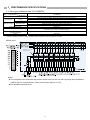
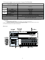
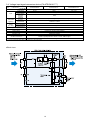
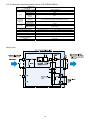
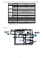
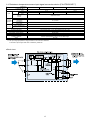
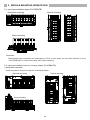
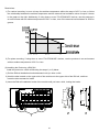
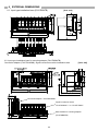
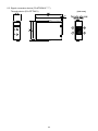
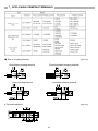
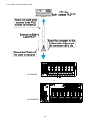
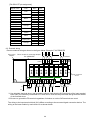
Analog Signal Conversion Module FA-ATB8XTB, FA-ATKB8XTB FA-ATKAA8XM FA-ATSVM1X***** FA-ATFTMXY User's Manual Thank you for purchasing FA Goods product. Before using, please read this User’s Manual and the relevant manuals carefully to ensure correct use. SAFETY PRECAUTIONS (Always read these precautions prior to use.) Before using this product, please read this User’s Manual and the relevant manuals carefully and pay full attention to safety to handle the product correctly. The precautions presented in this manual are concerned with this product only. For programmable logic controller system safety precautions, refer to the User’s Manual of the programmable logic controller to be used. In this manual, the safety precautions are classified into two levels: " WARNING" and " CAUTION". WARNING Indicates that incorrect handling may cause hazardous conditions, resulting in death or severe injury. CAUTION Indicates that incorrect handling may cause hazardous conditions, resulting in minor or moderate injury or property damage. Under some circumstances, failure to observe the precautions given under " CAUTION" may lead to serious consequences. Observe the precautions of both levels because they are important for personal and system safety. 1 [Design Precautions] WARNING Configure safety circuits external to the product to ensure that the entire system operates safely even when a fault occurs in the external power supply or the product. Failure to do so may result in an accident due to an incorrect output or malfunction. [Design Precautions] CAUTION Do not install the control lines or communication cables together with the main circuit lines or power cables. Keep a distance of 100mm (3.94 inches) or more between them. Failure to do so may result in malfunction due to noise. At power on/off, voltage or current may instantaneously be output from the output terminal of this module. In such case, wait until the analog output becomes stable to start controlling the external device. [Installation Precautions] WARNING Shut off the external power supply (all phases) before installation. Failure to do so may result in electric shock. 2 [Installation Precautions] CAUTION Use the product in an environment that meets the general specifications in this User’s Manual. Failure to do so may result in electric shock, fire, malfunction, or damage to or deterioration of the product. Use an input device type. Mistaken use of an output device type results in the risk of failure. Securely fix the module with a DIN rail or mounting screws. Incorrect mounting may cause malfunction, failure or drop of the module. Tighten the screw within the specified torque range. Undertightening can cause drop of the screw, short circuit or malfunction. Overtightening can damage the screw and/or module, resulting in drop, short circuit, or malfunction. Shut off the external power supply for the system in all phases before mounting or removing the module. Failure to do so may result in damage to, malfunction, or failure of the product. Do not directly touch any conductive parts and electronic components of this product. Doing so can cause malfunction or failure of the product. In attaching a signal conversion device to the Installation Base and performing conveyance and attachment to a board, please work by holding the Installation Base. If it works by holding a device, it will become device coming off and a cause of failure. [Wiring Precautions] WARNING Shut off the external power supply for the system in all phases before installation and wiring. Failure to do so may result electric shock or product damage. 3 [Wiring Precautions] CAUTION Individually ground the FG terminals of the product with a ground resistance of 100 Ω or less. Failure to do so may result in electric shock or malfunction. Use applicable solderless terminals and tighten them within the specified torque range. If any spade solderless terminal is used, it may be disconnected when the terminal screw comes loose, resulting in failure. Check the rated voltage and terminal layout before wiring to the module, and connect the cables correctly. Connecting a power supply with a different voltage rating or incorrect wiring may cause a fire or failure. Do not install the control lines or communication cables together with the main circuit lines or power cables. Keep a distance of 100mm (3.94 inches) or more between them. Failure to do so may result in malfunction due to noise. Place the cables in a duct or clamp them. If not, dangling cables may swing or inadvertently be pulled, resulting in damage to the module or cables or malfunction due to poor connection. Tighten the terminal screw within the specified torque range. Undertightening can cause short circuit, fire, or malfunction. Overtightening can damage the screw and/or module, resulting in drop, short circuit, or malfunction. Install the connector to the module securely. Failure to do so may cause malfunction. When disconnecting the cable from the module, do not pull the cable by the cable part. For a cable with connector, hold the connector by hand and pull it out. For a cable connected to a terminal block, loosen the terminal block screws first before removing the cable. Failure to do so may result in malfunction and damage to the module or cable. Before connecting the cables, check the type of interface to be connected. Connecting or erroneous wiring to the wrong interface may cause failure to the module and external devices. Prevent foreign matter such as dust or wire chips from entering the module. Such foreign matter can cause a fire, failure, or malfunction. This product must be installed to control panels. Connect the main power supply to this product in the control panel through a relay terminal block. Wiring and replacement of a this product must be performed by qualified service personnel who is familiar with protection against electric shock. Keep a distance of 100mm (3.94 inches) or more between a thermocouple and the main circuit line or AC control lines. Also, keep the thermocouple away from a circuit that includes harmonics, such as a high-voltage circuit and a load circuit of an inverter. Do not place the module near a device that generates magnetic noise. When connecting programmable logic controller, check that the product configuration are correct. The modules may be failure or malfunction if the configuration is incorrect. For each module, please load the correct modules depending on their external input signal. The wrong loading of the modules could occur failures on the external sensor. 4 Install the device in the unit surely. It causes the malfunction by damage, the drop, and the poor contact if not correctly installed. Moreover, mounting or removing the device it according to a correct procedure. It causes the malfunction by damage, the drop, and the poor contact if not correctly mounting or removing the module. Use it with power doesn't join the connector of this product. Failure or disconnection may cause malfunction. Install the protection cover and device in an unused connector and empty slot of the module. If the cover etc. are not installed, it causes a fire, the failure, and the malfunction by the foreign body. [Startup and Maintenance Precautions] WARNING Do not touch any terminal while power is on. Doing so will cause electric shock or malfunction. Shut off the external power supply for the system in all phases before cleaning the module or retightening the terminal screws, connector screws, or module fixing screws. Failure to do so may result in electric shock or cause the module to fail or malfunction. Undertightening can cause drop of the screw, short circuit or malfunction. Overtightening can damage the screw and/or module, resulting in drop, short circuit, or malfunction. [Startup and Maintenance Precautions] CAUTION Do not disassemble or modify the modules. Doing so may cause failure, malfunction, injury, or a fire. Use any radio communication device such as a cellular phone or PHS (Personal Handy phone System) more than 25cm (9.85 inches) away in all directions from the programmable logic controller, this product. Failure to do so may cause malfunction. Shut off the external power supply for the system in all phases before mounting or removing the module. Failure to do so may cause the module to fail or malfunction or damage. After the first use of the product, do not mount/remove the module, and the cable more than 50 times (IEC 61131-2 compliant) respectively. Exceeding the limit of 50 times may cause malfunction. Startup and maintenance of a control panel must be performed by qualified maintenance personnel with knowledge of protection against electric shock. Lock the control panel so that only qualified maintenance personnel can operate it. Before handling the module, touch a grounded metal object to discharge the static electricity from the human body. Failure to do so may cause the module to fail or malfunction. 5 [Disposal Precautions] CAUTION When disposing of this product, treat it as industrial waste. [Transportation Precautions] CAUTION The shock that exceeds the range of the general specification during transportation must avoid this product for the precision instrument. Doing so results in the risk of failure. When fumigants that contain halogen materials such as fluorine, chlorine, bromine, and iodine are used for disinfecting and protecting wooden packaging from insects, they cause malfunction when entering our products. Please take necessary precautions to ensure that residual fumigant components do not enter our products, or treat the packaging with methods other than fumigation (such as a heat method). Additionally, disinfect and protect wood from insects before packing the products. EMC and Low Voltage Directives Compliance to the EMC Directive, which is one of the EU Directives, has been a legal obligation for the products sold in European countries since 1996 as well as the Low Voltage Directive since 1997. Manufacturers who recognize their products are compliant to the EMC and Low Voltage Directives are required to declare that print a "CE mark" on their products. (1) Authorized representative in Europe Authorized representative in Europe is shown below. Name: Mitsubishi Electric Europe B.V. Address: Gothaer strasse 8, 40880 Ratingen, Germany (2) For the conformity to EMC and Low Voltage Directive of FA - Goods To configure a system meeting the requirements of the EMC and Low Voltage Directives when incorporating the FA-Goods (EMC and Low Voltage Directives compliant) into other machinery or equipment, refer to “EMC and Low Voltage Directives Compliant Manual_50D-FA9010-108”. Moreover, refer to the manual to compliant to EMC and Low Voltage Directives of PLC used. 6 CONTENTS 1. INTRODUCTION . . . . . . . . . . . . . . . . . . . . . . . . . . . . . . . . . . . . . . . . . . . . . . . . . . . . . . . . . . . . . . . . . . 8 2. GENERAL SPECIFICAION . . . . . . . . . . . . . . . . . . . . . . . . . . . . . . . . . . . . . . . . . . . . . . . . . . . . . . . . . . 8 3. PERFORMANCE SPECIFICATIONS . . . . . . . . . . . . . . . . . . . . . . . . . . . . . . . . . . . . . . . . . . . . . . . . . . 3.1. Input type installation base (FA-ATB8XTB) . . . . . . . . . . . . . . . . . . . . . . . . . . . . . . . . . . . . . . . . 3.2. Input type installation base for mounting adapter (FA-ATB8XTB) . . . . . . . . . . . . . . . . . . . . . . . 3.3. Conversion adapter current connection (2 outputs) (FA-ATKAA8XM) . . . . . . . . . . . . . . . . . . . 3.4. Voltage input signal conversion device (FA-ATSVM1XV****) . . . . . . . . . . . . . . . . . . . . . . . . . . 3.5. Current input signal conversion device (FA-ATSVM1XA420) . . . . . . . . . . . . . . . . . . . . . . . . . . 3.6. 2-wire system transmission equipment input signal conversion device . . . . . . . . . . . . . . . . . . . 3.7. Thermo-couple temperature input signal conversion device (FA-ATSVM1XT*) . . . . . . . . . . . . 3.8. Resistance temperature sensor input signal conversion device (FA-ATASVM1XR***) . . . . . . . 3.9. Through device (FA-ATFTMXY) . . . . . . . . . . . . . . . . . . . . . . . . . . . . . . . . . . . . . . . . . . . . . . . . . 9 9 10 11 12 13 14 15 17 18 4. Installing the Conversion adapter and Signal conversion device . . . . . . . . . . . . . . . . . . . . . . . . . . . . . 4.1. Installing the signal conversion device . . . . . . . . . . . . . . . . . . . . . . . . . . . . . . . . . . . . . . . . . . . 4.2. Installing the conversion adapter . . . . . . . . . . . . . . . . . . . . . . . . . . . . . . . . . . . . . . . . . . . . . . . . 19 19 19 5. MODULE MOUNTING ORIENTATION . . . . . . . . . . . . . . . . . . . . . . . . . . . . . . . . . . . . . . . . . . . . . . . . . 5.1. Input type installation base (FA-ATB8XTB) . . . . . . . . . . . . . . . . . . . . . . . . . . . . . . . . . . . . . . . . 5.2. Input type installation base for mounting adapter (FA-ATKB8XTB) . . . . . . . . . . . . . . . . . . . . . . 20 20 20 6. EXTERNAL DIMENSIONS . . . . . . . . . . . . . . . . . . . . . . . . . . . . . . . . . . . . . . . . . . . . . . . . . . . . . . . . . . 6.1. Input type installation base (FA-ATB8XTB) . . . . . . . . . . . . . . . . . . . . . . . . . . . . . . . . . . . . . . . . 6.2. Input type installation base for mounting adapter (FA-ATKB8XTB) . . . . . . . . . . . . . . . . . . . . . . 6.3. Signal conversion device (FA-ATSVM1X*****) . . . . . . . . . . . . . . . . . . . . . . . . . . . . . . . . . . . . . . 22 22 22 23 7. APPLICABLE CRIMPING TERMINALS . . . . . . . . . . . . . . . . . . . . . . . . . . . . . . . . . . . . . . . . . . . . . . . . 24 8. CONNECTED TARGET MODEL/PLC MODULE, CONNECTION CABLE . . . . . . . . . . . . . . . . . . . . . . 8.1. Input type installation base (FA-ATB8XTB) . . . . . . . . . . . . . . . . . . . . . . . . . . . . . . . . . . . . . . . . 8.2. Input type installation base for mounting adapter (FA-ATKB8XTB) . . . . . . . . . . . . . . . . . . . . . . 25 25 25 9. INSTALLATION METHOD . . . . . . . . . . . . . . . . . . . . . . . . . . . . . . . . . . . . . . . . . . . . . . . . . . . . . . . . . . . 26 9.1. Connection example with terminal block PLC module . . . . . . . . . . . . . . . . . . . . . . . . . . . . . . . . 26 9.2. External wiring . . . . . . . . . . . . . . . . . . . . . . . . . . . . . . . . . . . . . . . . . . . . . . . . . . . . . . . . . . . . . . . 29 10. PRECAUTIONS . . . . . . . . . . . . . . . . . . . . . . . . . . . . . . . . . . . . . . . . . . . . . . . . . . . . . . . . . . . . . . . . . . 30 11. GRATIS WARRANTY TERMS AND GRATIS WARRANTY RANGE . . . . . . . . . . . . . . . . . . . . . . . . . 31 12. WARRANTY PERIOD AFTER DISCONTINUATIO OF PRODUCTION ...................... 31 13. EXCLUSION OF OPPORTUNITY LOSS AND SECONDARY LOSS FROM WARRANTY LIABILITY . . . . . . 31 7 1.INTRODUCTION This user's manual explains the specification and handling of the Installation base (FA-ATB8XTB, FA-ATKB8XTB) and the conversion adapter (FA-ATKAA8XM) and the Signal conversion device (FA-ATSVM1X*****) and the Through device (FA-ATFTMXY) of the Analog signal conversion module, etc. By attaching the Signal conversion device to the Installation base, the Analog signal conversion module insulates between input and output and between channels, and changes and outputs various analog input signals, such as a sensor, to a predetermined signal. 2.GENERAL SPECIFICATIONS Item Specifications Operating ambient temperature 0 to 55°C Storage ambient temperature -25 to 75°C Operating ambient humidity 5 to 95% RH, no condensation Storage ambient humidity 5 to 95% RH, no condensation Compliant standards Under Vibration resistance intermittent vibration Under continuous vibration Shock resistance Operating atmosphere JIS B 3502, IEC61131-2 Frequency Acceleration Amplitude 5 to 8.4Hz ― 3.5mm 8.4 to 150Hz 9.8m/s2 (1G) ― 5 to 8.4Hz ― 1.75mm 8.4 to 150Hz 4.9m/s2 (0.5G) ― Sweep count 10 times each in X, Y, and Z axis directions ― Conforms to JIS B 3502 and IEC61131-2 (147m/s2 (15G), 3 times each in X, Y, and Z axis directions) There should be no corrosive gases. Operating altitude (*1) 2,000m or lower Installation location Inside control panel Overvoltage category (*2) II or lower Pollution level (*3) 2 or lower *1: Do not use or store in a pressurized environment greater than the atmospheric pressure at an altitude of 0m. *2: Indicates how an assumption has been made on the point at which the devices are connected from the public power grid to the machinery and equipment inside the facilities. *3: This is a guideline indicating the extent to which conducting substances are found in the environment in which the devices are used. 8 3.PERFORMANCE SPECIFICATIONS 3.1. Input type installation base (FA-ATB8XTB) Model name FA-ATB8XTB Item Number of slots Terminal block screws Terminal block Applicable wire Module mounting Mounting screws DIN rail External supply power Module consumption current (24VDC) 8 M3 screw, Pitch of 7.62mm, spring-up screw with finger protector cover Terminal screw tightening torque range: 58.8 to 88.2N・cm (6 to 9kgf·cm) 2 Applicable wire: 0.5 to 1.25mm M4 × 0.7mm × 20mm or greater Tightening torque range: 78 to 118N·cm (8 to 12kgf·cm) Applicable DIN rail: TH35-7.5Fe, TH35-7.5Al (conform to JIS C 2812) 24VDC±10% 6mA or less (exclude current for Signal Conversion Device) Dielectric withstand voltage, Between input and output and power supply: 750 VAC 1 minute, 10MΩ or higher insulation resistance Weight About 320g *1: Please install the dummy device (FA-ATNDM) in an unused slot to do an empty slot. *2: When connecting a cable to a module, a cable connector is pushed in until it is locked of a connector. ●Block chart Connector for signal conversion device Notes: The equipment connected with the monitor output must use the one with very large input resistance. (1MΩ or more is recommended.) The monitor output signal is 1 to 5V. Use shielded electrical wires. 9 3.2. Input type installation base for mounting adapter (FA-ATKB8XTB) Model name FA-ATKB8XTB Item Number of slots screw Terminal block Applicable wire, (IN1, OUT2) Tightening torque 8 M3 screw, Pitch of 7.62mm, spring-up screw with finger protector cover 2 AWG 22 to AWG 14: 0.3-2mm (with solderless terminal use), 58.8-88.2N•cm (6-9kgf•cm) M4 × 0.7mm × 20mm or greater Mounting screws Module Tightening torque range: 78 to 118N•cm (8 to 12kgf•cm) mounting DIN rail Applicable DIN rail: TH35-7.5Fe, TH35-7.5Al (conform to JIS C 2812) External supply power 24VDC±10% 24VDC: 6mA or less Module consumption current (exclude current for Conversion Adapter and Signal Conversion Device) Dielectric withstand voltage, Each input channels, each output channels, and between power supply: insulation resistance 750 VAC 1 minute, 10MΩ or higher Weight About 370g *1: Please install the dummy device (FA-ATNDM) in an unused slot to do an empty slot. ●Block chart Notes: Use shielded electrical wires. Note that the SLD terminals of the input terminal block (IN1) are internally connected to FG and can be used as relay terminals that ground the shields of the external wires. 10 3.3 Conversion adapter current connection (2 outputs) (FA-ATKAA8XM) Model name FA-ATKAA8XM Item Number of points Input signal Accuracy (While full scale) 8 Depends on the output of dedicated Signal conversion device (*1) (1 to 5V DC) Standard accuracy ±0.1% or less (ambient temperature 25°C±5°C) Temperature characteristics Interface Output Signal Permissible load resistance Interface Output Signal Permissible load resistance (*4) Response speed Power supply Module consumption current Isolation method ±0.015%/°C or less MIL20pin connector Output 1 4 to 20 mA (OUT1) 250Ω to 350Ω By output of extend base unit Output 2 4 to 20 mA (OUT2) 600Ω or less 10ms or less 24V DC ±10% (via base module for mounting adapter) 24V DC: 310mA or less (via base module for mounting adapter) Lump outputs (OUT1) with inputs and outputs (OUT2) with each channels: Transformar isolation Lump outputs (OUT1) with inputs, outputs (OUT2) with each channels, and between power Dielectric withstand voltage, insulation resistance supply: 750VAC 1minute, 10MΩ or higher Weight About 200g * 1: Current signal input of the Through module (FA-ATFTMXY) is not applicable. * 2: Please combine the characteristics of signal conversion device that are combined when using the products. Calculate the accuracy in the following method. Example: When using FA-ATSVM1XA420 Standard accuracy: ±0.2% = ±0.1% (Conversion adapter) + ±0.1% (Signal conversion device) Temperature characteristics: ±0.030%/°C = ±0.015%/°C (Conversion adapter) + ±0.015%/°C (Signal conversion device) * 3: When connecting a cable, a cable connector is pushed in until it is locked of a connector. * 4: It is time until it becomes 90% of an output to a rise pulse input. ●Block chart 11 3.4. Voltage input signal conversion device (FA-ATSVM1XV****) Model name Item FA-ATSVM1XV05 FA-ATSVM1XV15 FA-ATSVM1XV1010 Number of points 1 point (1 channel) Input signal 0 to 5V 1 to 5V -10 to +10V Input resistance 1MΩ or higher Input Disconnection detection None function Standard ±0.1% or lower (Surrounding air temperature 25°C±5°C) Accuracy accuracy (Full-scale Temperature against.) ±0.015%/°C or lower characteristic Output signal 1 to 5V Output Output allowable (PLC side) 10kΩ or higher load resistance (*1) 15ms or lower Response speed Zero/Span Adjustment Zero adjustment range: -2 to 2%, Span adjustment range: 98 to 102% Power supply DC24V±10% (Supply by base module) Consumption current (DC24V) 20mA or lower Insulation type Transformer insulation Dielectric withstand voltage, Between Input/Output/Power: 750VAC 1 minute, 10MΩ or higher insulation resistance Weight About 30g *1: It is time until it becomes 90% of an output to a rise pulse input. ●Block chart 12 3.5. Current input signal conversion device (FA-ATSVM1XA420) Model name FA-ATSVM1XA420 Item Number of points 1 point (1 channel) Input signal 4 to 20mA Input resistance 250Ω Input Disconnection detection None function Standard ±0.1% or lower (Surrounding air temperature 25°C±5°C) Accuracy accuracy (Full-scale Temperature against.) ±0.015%/°C or lower characteristic Output signal 1 to 5V Output Output allowable (PLC side) 10kΩ or higher load resistance (*1) 15ms or lower Response speed Zero/Span Adjustment Zero adjustment range: -2 to 2%, Span adjustment range: 98 to 102% Power supply DC24V±10%(Supply by base module) Consumption current (DC24V) 20mA or lower Insulation type Transformer insulation Dielectric withstand voltage, Between Input/Output/Power: 750VAC 1 minute, 10MΩ or higher insulation resistance Weight About 30g *1: It is time until it becomes 90% of an output to a rise pulse input. ●Block chart 13 3.6. 2-wire system transmission equipment input signal conversion device (FA-ATSVM1XD) Model name FA-ATSVM1XD Item Number of points 1 point (1 channel) Input signal 2-wire system transmission equipment Input resistance 250Ω Input Disconnection detection None function Supply voltage DC26V±2V Power supply Max supply for 24mA current Transmission Short-circuit equipment Limitation current: 25 to 35mA protection Standard ±0.1% or lower (Surrounding air temperature 25°C±5°C) Accuracy accuracy (Full-scale Temperature against.) ±0.015%/°C or lower characteristic Output signal 1 to 5V Output Output allowable (PLC side) 10kΩ or higher load resistance (*1) 15ms or lower Response speed Zero/Span Adjustment Zero adjustment range: -2 to 2%, Span adjustment range: 98 to 102% Power supply DC24V±10%(Supply by base module) Consumption current (DC24V) 68mA or lower Insulation type Transformer insulation Dielectric withstand voltage, Between Input/Output/Power: 750VAC 1 minute, 10MΩ or higher insulation resistance Weight About 30g *1: It is time until it becomes 90% of an output to a rise pulse input. *2: Please keep in mind that a base unit has the restrictions by the attachment direction in the case of three or more set use. ●Block chart 14 3.7. Thermo-couple temperature input signal conversion device (FA-ATSVM1XT*) [K Thermo-couple] Model name Item FA-ATSVM1XTK FA-ATSVM1XTK0040 Number of points Input signal Accuracy (Full-scale against.) Output (PLC side) FA-ATSVM1XTK0080 1 point(1 channel) K Thermo-couple Type Input FA-ATSVM1XTK0060 Measurement range Input resistance Disconnection detection function Standard accuracy Error margin of linearization Temperature characteristic Cold junction compensation accuracy Output signal Output allowable load resistance -200 to 1200°C 0 to +400°C 0 to +600°C 0 to +800°C 1MΩ or higher Upper bound excess ±0.1% or lower (Surrounding air temperature 25°C±5°C) ±0.1% or lower ±0.015%/°C or lower ±0.5°C or lower (25°C±5°C), ±1°C or lower (0 to 55°C) 1 to 5V 10kΩ or higher (*1) Response speed Zero/Span Adjustment 100ms or lower Zero adjustment range: -2 to 2%, Span adjustment range: 98 to 102% Power supply DC24V±10%(Supply by base module) Consumption current (DC24V) Insulation type Dielectric withstand voltage, insulation resistance Weight 24mA or lower Transformer insulation Between Input/Output/Power: 750VAC 1 minute, 10MΩ or higher About 40g *1: It is time until it becomes 90% of an output to a rise pulse input. *2: The input range (temperature range) is fixation in the value of a statement. In demand of input ranges other than a statement, please ask. [B, S, E, T, R, J, N Thermo-couple] Model name Item FA-ATSVM1XTB FA-ATSVM1XTS Number of points Type Input signal Input Accuracy (Full-scale against.) Output (PLC side) Measurement range Input resistance Disconnection detection function Standard accuracy Error margin of linearization Temperature characteristic Cold junction compensation accuracy Output signal Output allowable load resistance (*3) B Thermo-couple S Thermo-couple +600 to +1700°C 0 to +1600°C FA-ATSVM1XTE FA-ATSVM1XTT 1 point(1 channel) E T Thermo-couple Thermo-couple -200 to +900°C -200 to +350°C FA-ATSVM1XTR FA-ATSVM1XTJ FA-ATSVM1XTN R Thermo-couple J Thermo-couple N Thermo-couple 0 to +1600°C -40 to +750°C -200 to +1250°C 1MΩ or higher Upper bound excess ±0.1% or lower (Surrounding air temperature 25°C±5°C) ±0.1% or lower ±0.015%/°C or lower ±0.5°C or lower (25°C±5°C), ±1°C or lower (0 to 55°C) 1 to 5V 10kΩ or higher Response speed Zero/Span Adjustment 100ms or lower Zero adjustment range: -2 to 2%, Span adjustment range: 98 to 102% Power supply DC24V±10% (Supply by base module) Consumption current (DC24V) Insulation type Dielectric withstand voltage, insulation resistance Weight 24mA or lower Transformer insulation Between Input/Output/Power: 750VAC 1 minute, 10MΩ or higher About 40g *3: It is time until it becomes 90% of an output to a rise pulse input. *4: The input range (temperature range) is fixation in the value of a statement. In demand of input ranges other than a statement, please ask. 15 ●Block chart 16 3.8. Resistance temperature sensor input signal conversion device (FA-ATSVM1XR***) Model name Item FA-ATSVM1XRPT FA-ATSVM1XRPT0010 Number of points Type Input signal Measurement range Input Disconnection detection function Standard accuracy Accuracy Error margin of (Full-scale linearization against.) Temperature characteristic Output signal Output Output allowable load (PLC side) resistance (*1) FA-ATSVM1XRPT0020 FA-ATSVM1XRJPT 1 point (1 channel) Pt100 -200 to +650°C JPt100 0 to +100°C 0 to +200°C Upper bound excess ±0.1% or lower (Surrounding air temperature 25°C±5°C) ±0.1% or lower ±0.010%/°C or lower 1 to 5V 10kΩ or higher Response speed Zero/Span Adjustment 100ms or lower Zero adjustment range: -2 to 2%, Span adjustment range: 98 to 102% Power supply 24VDC ±10% (Supply by base module) Consumption current (24VDC) Insulation type Dielectric withstand voltage, insulation resistance Weight 25mA or lower Transformer insulation Between Input/Output/Power: 750VAC 1 minute, 10MΩ or higher About 40g *1: It is time until it becomes 90% of an output to a rise pulse input. *2: The input range (temperature range) is fixation in the value of a statement. In demand of input ranges other than a statement, please ask. ●Block chart 17 -200 to +600°C 3.9. Through device (FA-ATFTMXY) Model name FA-ATFTMXY Item Number of points 1 point (1 channel ) (*1) Conversion type When signal is through When current → voltage is converted Resistance - 250Ω Resistor accuracy - ±0.1% or less Input Characteristic of - ±0.0025%/°C or less temperature of resistor Permissible I/O signal Voltage: 10V or less, Current: 20mA or less Weight About 30g *1: When current → voltage is converted, it should be short-circuited between base module terminal block A-C terminals. *2: When using conversion adapter, the Through module (FA-ATFTMXY) is not applicable. ●Block chart 18 4.Installing the Conversion adapter and Signal conversion device 4.1. Installing the signal conversion device 1) The signal conversion device is set to 1) An attachment-and-detachment hook is the slot of the base. pushed from both sides. attachment-anddetachment. 2) It inserts unit a signal conversion device attachment-and-detachment hook locks (there is sound) attachment-and- 2) A signal conversion device is drawn out with an attachment-and-detachment hook pressed down. detachment. Note Use an input device type (devices with purple lines). Mistaken use of an output device type (devices with orange lines) results in the risk of failure. Point (1) It works with the main body of installation Base without having the device part when installing it in transportation and the enclosure with the device installed on Base. (2) The dummy device (FA-ATNDM) is sold for dustproof measures when there is an empty slot in Base. 4.2. Installing the conversion adapter (When using FA-ATKB8XTB) Specified installation torque: 36-48N•cm (3.7-4.8kgf•cm) 19 5.MODULE MOUNTING ORIENTATION 5.1. Input type installation base (FA-ATB8XTB) Horizontal mounting Vertical mounting Plane mounting Restriction: Please adjust the surrounding air temperature to 50°C or less when you use three devices or more "FA-ATSVM1XD" at “Vertical mounting” and “Plane mounting”. 5.2. Input type installation base for mounting adapter (FA-ATKB8XTB) (1)Installation Orientation Install the product using one of the four orientations below. Horizontal mounting Vertical mounting Plane mounting 20 Restrictions: 1) For vertical mounting, be sure to keep the ambient temperature within the range of 45˚C or less, or follow the relationship between the ambient temperature and the external load resistance value of output 2 shown in the graph on the right. Additionally, if using three or more "FA-ATSVM1XD" devices, use the products in an environment with an ambient temperature of 50˚C or less, even if the external load resistance is 250Ω or greater. 2) For plane mounting, if using three or more "FA-ATSVM1XD" devices, use the products in an environment with an ambient temperature of 50˚C or less. (2) Installing the Product to a DIN Rail Install the product to a DIN rail following the steps 1) to 3) below. 1) Pull the DIN rail installation hooks downward until you hear a click. 2) Hook the tabs located on the upper side of the module onto the upper side of the DIN rail, and then insert the tabs rearward to install. 3) Insert the DIN rail installation hooks of the module until you hear a click, locking the hooks. 21 6.EXTERNAL DIMENSIONS 6.1. Input type installation base (FA-ATB8XTB) [Unit: mm] 6.2. Input type installation base for mounting adapter (FA-ATKB8XTB) Conversion adapter (FA-ATKAA8XM), Signal conversion module installation state [Unit: mm] Conversion adapter(FA-ATKAA8XM) Signal conversion device "FA-ATSVM1X****" or "FA-ATFTMXY" Base module for mounting adapter (FA-ATKB8XTB) 22 6.3. Signal conversion device (FA-ATSVM1X*****) Through device (FA-ATFTMXY) 23 [Unit: mm] 7.APPLICABLE CRIMPING TERMINALS ● Size of crimping terminal [Unit: mm] Round bare crimping terminal Round insulated crimping terminal Y bare crimping terminal Y insulated crimping terminal ● Terminal trapezoid [Unit: mm] 24 8.CONNECTED TARGET MODEL/PLC MODULE, CONNECTION CABLE 8.1. Input type installation base (FA-ATB8XTB) PLC Module Model MELSEC-Q Series Analog input module Connection Cable Model Q68ADV Q68ADV FA-CBL**ATQ8XVT Conversion adapter: FA-Q6TCA FA-CBL**ATQ8XVA AJ65BT-64AD CC-Link Analog input module AJ65SBT-64AD FA-CBL**ATF AJ65SBT2B-64AD Each company PLC General analog input Module General analog input module FA-CBL**ATF 8.2. Input type installation base for mounting adapter (FA-ATKB8XTB) (When using FA-ATKAA8XM) PLC Module Model MELSEC-Q Series Analog input module Connection Cable Model Q68ADI Q68ADI FA-CBL**ATQ8XVT Conversion adapter: FA-Q6TCA FA-CBL**ATQ8XVA AJ65BT-64AD CC-Link Analog input module AJ65SBT-64AD FA-CBL**ATF AJ65SBT2B-64AD Each company PLC General analog input module General analog input module 25 FA-CBL**ATF 9.INSTALLATION METHOD 9.1. Connection example with terminal block PLC module 9.1.1. When cable with terminal block is used. Attach the terminal block securely to the PLC module with attachment screws PLC module *1 Connection cable Insert the connector to the back, and then fully secure the connector with a clip. *1 Ground the FG wire to the panel (ground both terminals) FA-ATB8XTB or FA-ATKB8XTB *1 ground the FG wire of the cable to the panel. 26 9.1.2 When terminal block - connector conversion adapter is used. FA-ATB8XTB or FA-ATKB8XTB *1: Ground the FG wire of the cable to the panel. 27 9.1.3. When rose line cable is used. FA-ATB8XTB or FA-ATKB8XTB 28 [FA-CBL*ATF pin assignment] Core wire Signal name Dots color CH1+ 2 Pink CH12 CH2+ 2 Yellow CH22 CH3+ 2 White CH32 CH4+ 2 Light gray CH42 CH5+ 2 Orange CH52 CH6+ 2 Pink CH61 CH7+ 1 Yellow CH71 CH8+ 1 White CH81 NC 1 Light gray NC 1 FG 1 Orange FG 1 Dot color Black Red Black Red Black Red Black Red Black Red Black Red Black Red Black Red Black Red Black Red 9.2. External wiring Execute external wiring as shown in the figure below. Example: FA-ATKB8XTB Conversion adapter Base module for mounting adapter FA-ATKB8XTB CH1 CH2 CH3 CH8 *1 OUTPUT2 OUT2 CH1 CH2 CH3 CH4 CH5 CH6 CH7 CH8 PW Signal conversion device IN1 INPUT *2 FG + - 24VDC CH1 CH2 CH3 CH8 *1 *1: Use shielded electrical wires, and ground the shields. Note that the SLD terminals of the input terminal block (IN1) are internally connected to FG and can be used as relay terminals that ground the shields of the external wires. *2: Be sure to ground the FG terminal regardless of whether or not the SLD terminals are used. The wiring to the input terminal block (IN1) differs according to the mounted signal conversion device. The wiring to the base module by each device is as shown below. 29 ●Wiring connection diagrams of wiring to base module by signal conversion device Voltage input (FA-ATSVM1XV****) Resistance bulb (FA-ATSVM1XR***) Current input (FA-ATSVM1XA420) 2-wire transmitter (FA-ATSVM1XD) Thermocouple temperature (FA-ATSVM1XT*) Through device (FA-ATFTMXY) *2 When current → voltage is converted When signal is through Base module for mounting adapter Resistance bulb (three-wire type) A A B B b C *1: Secure the end (round solderless terminal) of the RJC sensor of the thermocouple temperature input device to the terminal block. The round solderless terminal area and device internal circuit are electrically isolated. Please do not strongly pull, do not twist, and do not bend RJC sensor of the thermocouple temperature input signal conversion device. It becomes a cause of failure of a RJC sensor. *2: Signals other than voltage input (1-5V) are not applicable, when using FA-ATKB8XTB. 10.PRECAUTIONS (1) Please go through a warm-up to make sure for ten minutes or more though this module works at the same time as turning on the power supply. (2) Because signal isolation conversion device had been proofread when having shipped it, it is not necessary to proofread again. However, please Zero/Span adjust it according to the following when the adjustment with connected equipment is taken or the customer executes the proofreading. (Trimmer operation/// Right(Clockwise)Rotation;Largeness, Left(Counterclockwise)Rotation;Smallness) 1) Please go through a warm-up for ten minutes or more after turning on the power supply of the module. 2) The signal equivalent to 0% in the input range is input, the Zero adjustment trimmer is adjusted, and the output signal is matched to 0%. 3) The signal equivalent to 100% in the input range is input, the Span adjustment trimmer is adjusted, and the output signal is matched to 100%. 4) Please repeat above-mentioned 2) to 3) several times and adjust Zero/Span completely. 5) Please input the signal within range 25%, 50%, 75% of the input, and confirm the linearity of the output. (3) When the monitor output is used, the handling is different according to the usage condition of the device. Please see the following tables about handling by each device. 30 11.GRATIS WARRANTY TERMS AND GRATIS WARRANTY RANGE If any fault or defect (hereinafter referred to as “Failure”) attributable to Mitsubishi Electric should occur within the gratis warranty period, Mitsubishi Electric shall replace the product free of charge via the distributor from whom you made your purchase. ●Gratis Warranty Period The gratis warranty period of this product shall be one (1) year from the date of purchase or delivery to the designated place. ●Gratis Warranty Range (1) The gratis warranty range shall be limited to normal use based on the usage conditions, methods and environment, etc., defined by the terms and precautions, etc., given in the instruction manual, user’s manual, and caution labels on the product. (2) In the following cases, a repair fee shall be applied even if within the gratis warranty period. 1) Failure resulting from inappropriate storage or handling, carelessness or negligence by the user, or Failure caused by the user’s hardware or software design. 2) Failure caused by unapproved modifications, etc., to the product by the user. 3) Failure that could have been avoided if, when the Mitsubishi Electric Engineering product was assembled into the user’s device, safeguards defined by legal regulations applicable to the user’s device or functions or structures considered standard by the industry had been provided. 4) Failure recognized as preventable if the consumed products specified in instruction manuals, etc., were normally maintained or replaced. 5) Replacement of consumable parts (relays, etc.). 6) Failure caused by external factors beyond anyone’s control such as fires or abnormal voltage, and Failure caused by Force Majeure such as earthquakes, lightning, or wind and water damage. 7) Failure caused by reasons unpredictable by scientific technology standards at the time of shipment from Mitsubishi Electric Engineering. 8) Any other failure not attributable to Mitsubishi Electric Engineering or found by the user to not be attributable to Mitsubishi Electric Engineering. 12. WARRANTY PERIOD AFTER DISCONTINUATION OF PRODUCTION (1) MEE shall offer product repair services (fee applied) for seven (7) years after production of the product has been discontinued. Discontinuation of production shall be reported via distributors. (2) Product supply (including spare parts) is not possible after production has been discontinued. 13. EXCLUSION OF OPPORTUNITY LOSS AND SECONDARY LOSS FROM WARRANTY LIABILITY Regardless of the gratis warranty period, MEE shall not be liable for compensation for damages arising from causes not attributable to MEE, opportunity losses or lost profits incurred by the user due to Failures of MEE products, damages or secondary damages arising from special circumstances, whether foreseen or unforeseen by MEE, compensation for accidents, compensation for damages to products other than MEE products, or compensation for other work carried out by the user. 31 FOR YOUR SAFETY This product has been manufactured as a general-purpose product for general industry applications, etc. The product is not intended for use in devices or systems used under conditions in which human life could be greatly affected. When considering application of this product to special applications, such as nuclear power, electrical power, aerospace, medical, or manned transport devices or systems, contact our sales service desk. Although this product was manufactured under a strict quality management system, the product shall be systematically provided with backup and fail-safe functions when applied to equipment that may lead to a major accident or damage in the unlikely event any failure or defect should occur in the product. 1-13-5 Kudankita, Chiyoda-ku, Tokyo, Japan 102-0073 Homepage URL: http://www.mee.co.jp/ During product use, be sure to ensure safety in the unlikely event failure occurs. Mitsubishi Electric Engineering assumes no responsibility whatsoever for any secondary damage caused by the failure of this product. 50D-FA9010-122-B Information such as specifications is subject to change without notice. Developed March 2014 32