1
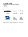
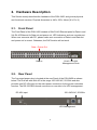
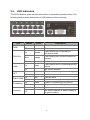
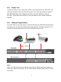
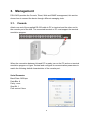
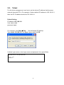
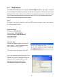
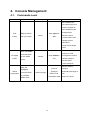
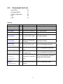
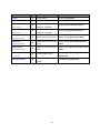
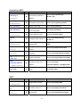
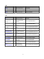
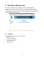
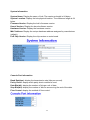
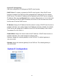
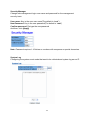
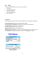
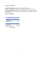
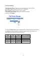
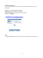
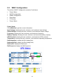
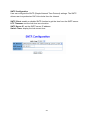
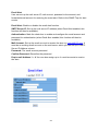
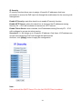
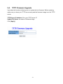
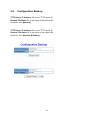
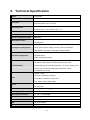
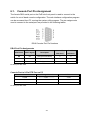
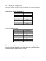
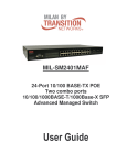
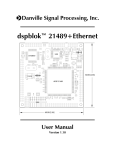
LevelOne POH-2450 24-Port PoE Midspan Hub User Manual Ver. 1.0-0704 FCC Warning This equipment has been tested and found to comply with the limits for a Class A digital device, pursuant to Part 15 of the FCC Rules. These limits are designed to provide reasonable protection against harmful interference when the equipment is operated in a commercial environment. This equipment generates, uses, and can radiate radio frequency energy and, if not installed and used in accordance with this manual, may cause harmful interference to radio communications. Operation of this equipment in a residential area is likely to cause harmful interference in which case the user will be required to correct the interference at his own expense. CE Mark Warning This is a Class-A product. In a domestic environment this product may cause radio interference in which case the user may be required to take adequate measures. II Table of Contents 1. INTRODUCTION ................................................................................................. 1 1.1. 1.2. 2. HARDWARE DESCRIPTION.............................................................................. 3 2.1. 2.2. 2.3. 2.4. 2.5. 3. FEATURES ...................................................................................................... 1 PACKAGE CONTENTS ...................................................................................... 2 FRONT PANEL ................................................................................................. 3 REAR PANEL .................................................................................................. 3 LED INDICATORS ............................................................................................ 4 POWER ON .................................................................................................... 5 NETWORK APPLICATION................................................................................... 5 MANAGEMENT .................................................................................................. 6 3.1. CONSOLE ....................................................................................................... 6 Serial Parameter ................................................................................................. 6 3.2. TELNET .......................................................................................................... 8 Default Setting..................................................................................................... 8 3.3. WEB-BASED ................................................................................................... 9 Default Setting..................................................................................................... 9 4. CONSOLE MANAGEMENT.............................................................................. 10 4.1. COMMANDS LEVEL ........................................................................................ 10 4.2. COMMANDS SET LIST .....................................................................................11 System ...............................................................................................................11 SNMP ................................................................................................................ 13 TFTP ................................................................................................................. 13 SystemLog, SMTP ............................................................................................ 14 SNTP................................................................................................................. 14 UPS ................................................................................................................... 15 PoE.................................................................................................................... 15 5. WEB-BASED MANAGEMENT ......................................................................... 16 5.1. SYSTEM ....................................................................................................... 16 System Information ........................................................................................... 17 Console Port Information................................................................................... 17 System IP Configuration.................................................................................... 18 Security Manager .............................................................................................. 19 III System Log ....................................................................................................... 19 5.2. POE ............................................................................................................ 20 PoE Status......................................................................................................... 20 Controller Temperature...................................................................................... 21 PoE Power Manage........................................................................................... 22 POE Port Configuration ..................................................................................... 23 PoE Port Status ................................................................................................. 24 5.3. MISC CONFIGURATION ................................................................................. 25 Power Status ..................................................................................................... 25 SNTP Configuration........................................................................................... 26 SNMP Configuration.......................................................................................... 27 Email Alert ......................................................................................................... 29 IP Security ......................................................................................................... 30 5.4. TFTP FIRMWARE UPGRADE .......................................................................... 31 5.5. CONFIGURATION BACKUP .............................................................................. 32 5.6. SAVE CONFIGURATION .................................................................................. 33 5.7. FACTORY DEFAULT ........................................................................................ 33 5.8. SYSTEM REBOOT .......................................................................................... 33 6. TECHNICAL SPECIFICATION ......................................................................... 34 6.1. 6.2. CONSOLE PORT PIN ASSIGNMENT .................................................................. 35 RJ-45 PIN ASSIGNMENT ................................................................................ 36 IV 1. Introduction POH-2450 follows the IEEE 802.3af and is completely compatible with existing Ethernet switches and networked devices. Because the Power Sourcing Equipment (PSE) tests whether a networked device is PoE-capable, power is never transmitted unless a Powered Device is at other end of the cable. It also continues to monitor the channel. If the Powered Device does not draw a minimum current, because it has been unplugged or physically turned off, the PSE shuts down the power to that port. Optionally, the standard permits Powered Devices to signal to the PSEs exactly how much power they need. This allows greater flexibility in the locating of network devices and significantly decreasing installation costs in many cases. 1.1. Features Complies to 802.3af Power Over Ethernet 400W full powered supply Complies to IEEE802.3 10BASE-T, 802.3u 100BASE-TX Support 802.3af pre-standard PD Support power feeding priority Temperature monitoring Power limit setting TFTP firmware update System log Configuration up-load and down-load SNMP / Web/Console/Telnet management Circuit shot protect Support Redundant Power Simple Network Time Protocol (SNTP) Simple Mail Transfer Protocol (SMTP) DHCP Client support SNMP Trap support Management IP address security Fan fail detect Command line support Power overloading protect 1 1.2. Package Contents Unpack the contents and verify them against the checklist below. - POH-2450 - Power Cord - RS-232 cable - CD Manual / Utility POH-2450 Console Cable Power Cord CD Manual / Utility Rack-mount Kit Rubber Pads Compare the contents of your POH-2450 package with the standard checklist above. IF any item is missing or damaged, please contact your local dealer for service. 2 2. Hardware Description This Section mainly describes the hardware of the POH-2450, and gives a physical and functional overview. Physical dimension is: 440 x 225 x 44mm (W x D x H) 2.1. Front Panel The Front Panel of the POH-2450 consists of 24x RJ-45 Ethernet ports for Data in and 24x RJ-45 Ethernet for Data out and power out, LED indicators, and one console port. When user connects with PD, please make sure connection of Data in and Data out and power out is correct. Otherwise, the PoE function will not work. Data + Power Out Data In 2.2. RJ-45 / RS-232 Management Ports Rear Panel The 3-pronged power plug is located at the rear Panel of the POH-2450 as shown below. The Hub will work with AC in the range 100-240V AC, 50-60Hz and also provides one DC 48V input for the extra power connection for the power redundant function. The RS-232 DB-9 female connector on rear side is for UPS management. DC 48V input 100~240V AC, 50/60Hz UPS Management 3 2.3. LED Indicators The LED Indicators gives real-time information of systematic operation status. The following table provides descriptions of LED status and their meaning. LED PWR FDX/COL LINK ACT FAN1~FAN4 Forwarding Overload Status On Color Green Description Power On Off -- Power is not connected. On Orange The Ethernet port is operating in full-duplex mode. Blink Orange The Ethernet port occurred collision of packets. Off -- In Half-duplex mode. On Green The Ethernet port is connecting with the device. Off -- No device attached. On Green The port is receiving or transmitting data. Off -- No data occurred On Red The fan failed. Off -- The fan is working functionally. On Green Power is transmitting to the device Off -- Power is not transmitting to the device On Green Device is overload or short. Off -- No device attached or power feeding is in good condition. 4 2.4. Power On Connect the power cord to the power socket on the rear panel of the POH-2450. The other side of power cord connects to the power outlet. The internal power supply of the POH-2450 works with voltage range of AC in the 100-240VAC, frequency 50~60Hz. Check the power indicator on the front panel to see if power is properly supplied. 2.5. Network Application The POH-2450 can provides power to the PD that follow the IEEE 802.3af standard in the network. It can solve the problem of position limitation. The following figure is an example of network application for Power over Ethernet inject Hub. PD (Powered Device) Data + Power POH-2450 Managed Switch Note: When the POH-2450 connects with the Cisco Aironet 350 Access Point, please use cross over cable for connection. For the other brands’ devices, please use non-cross over cable. 5 3. Management POH-2450 provides the Console, Telnet, Web and SNMP management, this section shows how to connect the device through different managing tools. 3.1. Console Attach one end of the supplied RS-232 cable to PC or terminal and the other end to the console port of the hub. The connected terminal or PC must support the terminal emulation program. When the connection between Hub and PC is ready, turn on the PC and run a terminal emulation program or Hyper Terminal and configure its communication parameters to match the following default characteristics of the console port: Serial Parameter Baud Rate: 9600 bps Data Bits: 8 Parity: none Stop Bit: 1 Flow control: None 6 After finished the parameter settings, click “OK“. When the blank screen shows up, press Enter key to bring out the login prompt. Key in the “root“(default value) for the both User name and Password (use Enter key to switch), then press Enter key and the Main Menu of console management appears. Please see below figure for login screen. POH-2450: 24-Port PoE Midspan Hub User Name : Password : CLI Management The system supports the console management – CLI command. After you login to the system, you will see a command prompt. To enter CLI management interface, enter “enable” command. Switch>enable Switch# 7 3.2. Telnet For the telnet management, user has to set the device IP address that the same network class with PC’s. For example; it factory default IP address is 192.168.16.1, then the PC IP address should be 192.168.16.x Default Setting IP Address: 192.168.16.1 User name: root password: root For example, click Start Æ Run... from Windows XP desktop Type telnet 192.168.16.1 into Open: space and click OK It shows login screen, enter login name and password, then press Enter POH-2450 24-Port PoE Midspan Hub Login: root Password: 8 3.3. Web-Based The Web-Based Management supports Internet Explorer 5.0 or up. And, it is applied for Java Applets for reducing network bandwidth consumption, enhance access speed and present an easy viewing screen. Before using web management, install the inject hub on the network and make sure that any one of PC on the network can connect with the inject hub through the web browser. Note: By default, user has to explicitly modify the IE browser setting to enable Java Applets to operate network ports. Default Setting IP Address: 192.168.16.1 Subnet Mask: 255.255.255.0 Default Gateway: 192.168.16.254 User Name: root Password: root System Login Launch the Internet Explorer on the PC, key in “http:// “+” the IP address of the hub”, and then Press “Enter”. The login screen will appear right after Key in the user name and password. The default user name and password are the same as “root”. Press “Enter” or ”OK”, and then the home screen of the Web-based management appears 9 4. Console Management 4.1. Commands Level Modes Access Method Prompt Exit Method About The available user commands at the user level are a subset of those available at the User Begin a session EXEC with your switch. Enter logout or switch> quit privileged level. Use this mode to • Perform Basic tests. • Display system information. • Enter the Privileged mode. The privileged command Enter the enable Privileged EXEC is advance mode command while in user EXEC Enter disable to switch# exit mode. Privileged this mode to • Display advance function status • save configures Use this mode to Enter the Global configuration configure command while switch(config)# To exit to configure privileged parameters that apply to EXEC mode, in privileged enter exit or end EXEC mode. 10 your switch as a whole. 4.2. Commands Set List User EXEC Privileged EXEC Global configuration PoE UPS E P G P U System Commands Level Description Example show system-info E Show system status switch>show system-info show version E Show version status switch>show version show config E Show switch configuration switch>show config show terminal P Show console status switch#show terminal Save user configuration into write memory G permanent memory (flash switch#write memory rom) write terminal system name [System Name] system location [System Location] system description [System Description] G G G G Display user configuration on terminal Configure system name Set switch system location string Set switch system [Subnet-mask] G switch(config)#system name xxx switch(config)#system location xxx switch(config)#system description xxx description string ip address [Ip-address] switch#write terminal Configure the IP address of switch switch(config)#ip address 192.168.1.1 255.255.255.0 192.168.1.254 [Gateway] ip dhcp [Enable|Disable] G Enable DHCP client function switch(config)#ip dhcp enable of switch 11 Commands Level Description Example reload G Reboot switch switch(config)#reload default G Restore to default Switch(config)#default username [Username] password [Password] security enable [Enable|Disable] http-server [Enable|Disable] telnet-server [Enable|Disable] address [1~10] [IP] show ip-security G G G G G G P Changes a login username. (maximum 10 words) Specifies a password (maximum 10 words) Enable IP security function switch(config)# username xxxxxx switch(config)# password xxxxxx switch(config)# ip-security enable Enable IP security of HTTP switch(config)# ip-security http-server server enable Enable IP security of telnet switch(config)# ip-security telnet-server server enable Set the IP security list Show the information of IP security 12 switch(config)# ip-security address 1 192.168.1.55 switch#show ip-oosecurity SNMP Commands snmp system-name [System Name] snmp system-location [System Location] Level G G Description Example Set SNMP agent system switch(config)#snmp system-name name l2switch Set SNMP agent system switch(config)#snmp system-location location lab Add SNMP community switch(config)#snmp community-strings string. public right rw Configure SNMP server switch(config)#snmp-server host host information and 192.168.1.50 community public community string. trap-version v1 snmp community-strings [Community] G right [RO/RW] snmp-server host [Host-address] community G [Community-string] no snmp-server host [Host-address] G no snmp community-strings G [Community] Remove SNMP server host Switch(config)#no snmp-server host information. 192.168.1.50 Remove SNMP community Switch(config)#no snmp string. community-strings public TFTP Commands Level Description Example Save configuration to TFTP copy flash:config.text tftp G and need to specify the IP switch(config)# copy flash:config.text of TFTP server and the file tftp name of image. Get configuration from TFTP server and need to tftp:config.text flash G specify the IP of TFTP switch(config)# tftp:config.text flash server and the file name of image. Upgrade firmware by TFTP tftp:firmware flash G and need to specify the IP of TFTP server and the file name of image. 13 switch(config)# tftp:firmware flash SystemLog, SMTP Commands systemlog ip [IP address] systemlog Level G Description Set System log server IP address. Example switch(config)# systemlog ip 192.168.1.100 G Set System Log Function switch(config)# systemlog enable show systemlog E Display system log. Switch>show systemlog show systemlog P [Enable|Disable] smtp [Enable|Disable] smtp ip [IP] smtp authentication [Enable|Disable] smtp account [account] smtp password [password] smtp [Enable|Disable] e-mail alert Enable SMTP function G Configure SMTP server IP G G G G G [1~4] [Mail address] show smtp server information G smtp recept-mail-address Show system log client & P switch#show systemlog switch(config)#smtp enable switch(config)#smtp serverip 192.168.1.5 Enable SMTP switch(config)#smtp authentication authentication enable Configure authentication account Configure authentication password switch(config)#smtp account User switch(config)#smtp password 123456 Enable e-mail alert switch(config)#smtp enable e-mail alert Set SMTP recept mail switch(config)#smtp address recept-mail-address 1 [email protected] Show the information of SMTP switch#show smtp SNTP Commands sntp enable [Enable|Disable] sntp ip [IP] sntp timezone [Timezone] Level Description Example G Enable SNTP function switch(config)#sntp enable G Set SNTP server IP switch(config)#sntp ip 192.169.1.1 G Set timezone switch(config)#sntp timezone Hawaii 14 UPS Commands Level Description Example power P Enter Power function. switch#power status G Show Power I/O status. switch(power)#status Info G Show Power info. switch(power)#info test10 G Test for 10 seconds. switch(power)#test10 PoE Commands poe Level P portebl [Enable|Disable] G [Ports] portplm [100~20000] [Port] system-power-limit [37~400] 8023af-pre-standard [Enable|Disable] temperature-alarm [1~2] [Temperature] power-management [1~5] G G G G G Description Enable PoE function. Port Enable & Disable configure. Port Power Limit Max Setting. Set system power limit value. Set IEEE 802.3af Example switch#poe switch(poe)#portebl enable 2 switch(poe)#portplm 15400 3 switch(poe)#system-power-limit 806 switch(poe)#8023af-pre-standard enable pre-standard. Set system temperature alarm. Set power management mode. switch(poe)#temperature-alarm 1 50 switch(poe)#power-management 5 show status G Show POE status. switch(poe)#show status show configure G Show POE configure. switch(poe)#show configure show system G show temperature G show power-management G Show POE system switch(poe)#show system information. Show POE system switch(poe)#show temperature temperature. Show POE power management mode. 15 switch(poe)#show power-management 5. Web-Based Management This section introduces the configuration and functions of the Web-Based management. On CPU board of the hub there is an embedded HTML web site residing in flash memory, which offers advanced management features and allow users to manage the hub from anywhere on the network through a standard browser such as Microsoft Internet Explorer. 5.1. System The System contains 5 sub-items, such as follows: System Information Console Port Information System IP Configuration Security Manager System Log. 16 System Information System Name: Display the name of hub. The maximum length is 64 bytes. System Location: Display the hub physical location. The maximum length is 64 bytes. Firmware Version: Display the hub’s firmware version. Kernel Version: Display the kernel software version. Hardware Version: Display the hardware version MAC Address: Display the unique hardware address assigned by manufacturer (default) PoE Chip Version: Display the chip version on main board. Console Port Information Baud Rate(bps): display the transmission rate (bits per second). Parity Check: display which parity check method is used. Data Bits(bit): display the number of bits per unit of data. Stop Bits(bit): display the number of bits for announcing the end of the data. Flow Control: display the method of flow control. 17 System IP Configuration User can configure the IP Settings and DHCP client function DHCP Client: To enable or disable the DHCP client function. When DHCP client function is enabled, the PoE hub will be assigned the IP address from the network DHCP server. The default IP address will be replaced by the DHCP server assigned IP address. After user click [Apply] button, a popup dialog show up. It is to inform the user that when the DHCP client is enabled, the current IP will lose and user should find the new IP on the DHCP server. IP Address: Assign the IP address that the network is using. If DHCP client function is enabled, and then user needn’t assign the IP address manually. Instead, the network DHCP server will assign the IP address for the PoE hub and display in this column. The default IP is 192.168.16.1 Subnet Mask: Assign the subnet mask of the IP address. If DHCP client function is enabled, and then user needn’t assign the subnet mask Gateway: Assign the network gateway for the PoE hub. The default gateway is 192.168.16.254 Gateway: Assign the network gateway for the PoE hub. The default gateway is 192.168.16.254 18 Security Manager Change web management login user name and password for the management security issue User name: Key in the new user name(The default is “root”) New Password: Key in the new password(The default is “root”) Confirm password: Re-type the new password And then, click [Apply] Note: Password requires 1-10 letters or numbers with no spaces or special characters System Log Configuring the system event mode that want to be collected and system log server IP 19 5.2. PoE The article of PoE contains 5 sub-items, such as follows: PoE Status Controller Temperature PoE Power Manage PoE Port Configuration PoE Port Status PoE Status PoE Status shows status of power usage including Power Consumption, Voltage, etc. Current Get Power: display the current get power (watts). Currently Power Consumption: display the currently power consumption. Currently Voltage: display the currently voltage. Current: display the load current (ampere). System Power Limit: the maximum power limit. IEEE 802.3af Pre-standard: to enable or disable IEEE 802.3af Pre-standard function. Click [Refresh] for getting newest status, and then click [Apply] to configure. 20 Controller Temperature Chipset & Port number: display the controller chip number. Current Temperature: display the current operating temperature of the chip. Set Temperature Alarm: set the number of temperature in centigrade. When the operating temperature of the chip reach the set number, the system will issue an alarm message. And then, click [Apply] 21 PoE Power Manage Total Allocated Power: display the total allocated power of the PoE hub. Port Power Limit: display the power limit to a single port. Start Condition: display the type of start condition. Power Management Mode: there are 5 modes for selecting. And then, click [Apply] An optional "Power Class" feature allows the PD to indicate its power requirements by changing the sense resistance at higher voltages. Power Class selection is depending on the amount of power they require. Mode Class Usage Power Level (watts) 1 0 Default 0.44 to 12.95 2 1 Optional 0.44 to 3.84 3 2 Optional 3.84 to 6.49 4 3 Optional 6.49 to 12.49 5 4 Reserved 22 POE Port Configuration The Port Configuration menu allows the user to control individual ports, and set-up parameters. Port: port 1 ~ port 24 are listed for selecting Port State: enable or disable the selected port. Power Limit Value: set the power limit value to the port. And then, click [Apply] Note: If change the Power values, make sure your PD does correspond to required power. 23 PoE Port Status The Port Status shows individual ports status and monitor their status. Port: display the port number. Status: display the status of the port. Forward Power: display the forwarding power which is provided by the hub. Current: display the current of the port. Class: display the class status. Event: display the related events to the port. And then, click [Refresh] to get the newest information. 24 5.3. MISC Configuration The article of MISC Configuration contains 5 sub-items: Power Status SNTP Configuration SNMP Configuration Email Alert IP Security Power Status Power Status Click [Refresh] to get the current information. Input Voltage: showing the real, minimum, and maximum input voltage. Output Voltage: showing the real, minimum, and maximum output voltage. Frequency: showing the real, minimum, and maximum frequency. Battery Capacity: showing the real, minimum, and maximum battery capacity. UPS Overload: showing the real, minimum, and maximum UPS overload. Temperature: showing the real, minimum, and maximum operating temperature. RatVoltage(Vac): display the Rat Voltage(Vac). RatVoltage(Vdc): display the Rat Voltage(Vdc). RatCurrent: display the RatCurrent. RatFrequence: display the RatFrequence. 25 SNTP Configuration User can configure the SNTP (Simple Network Time Protocol) settings. The SNTP allows user to synchronize PoE Hub clocks from the Internet. SNTP Client: enable or disable SNTP function to get the time from the SNTP server. UTC Timezone: set the hub time zone location. SNTP Server IP: set the SNTP server IP address Switch Timer: display the hub current time 26 SNMP Configuration Use this page to define management stations as trap managers and to enter SNMP community strings. You can also define a name, location and contract person for the switch System Options Enter the following information about the hub, as needed: Name: Enter a name to be used for the hub. Location: Enter the location of the PoE hub Contact: Enter the name of contact person or organization. Community Strings Community strings serve as password and can be entered as one of the following: Current Strings: User can remove the current strings or add new community strings. New Community Strings: Fill the column with name of string. Click [Add] To remove the community string, select the community string that you have defined and click [Remove]. You cannot remove the default community string set. RO: Read only. Enables requests accompanied by this string to display MIB-object information. RW: Read/write. Enables requests accompanied by this string to display MIB-object information and to set MIB objects. Trap Managers A trap manager is a management station that receives traps. The management station then generates alerts based on the received traps. If no trap manager is defined, no traps will be issued. Create a trap manager by entering the IP address of the station, a community string, and selects the SNMP version. IP Address: Enter the IP address of trap manager. Community: Enter the community string. Trap version: Select the SNMP trap version type – v1 or v2c 27 SNMP Trap Managed Ethernet port Link down/up. DC disconnect trap - PoE port Event Disconnect PDU off - PoE port event Over loading trap - PoE port event Short circuit trap - PoE port event Over Temp protection trap - PoE port event. Power management - PoE port off event Authentication fail trap Cold start trap Redundant Power (DC48V) disconnect trap (RPS-2450) Redundant power AC fault - Redundant power fault trap (RPS-2450) Battery Low Trap (RPS-2450) Fan fail trap (RPS-2450) * RPS-2450 is optional Redundant Power unit for the POH-2450 28 Email Alert User can set up the mail server IP, mail account, password to the account, and forwarded email account for receiving the event alert. Refer to the SNMP Trap for alert events. Email Alert: Enable or disable the email alert function. SMTP Server IP: Set up the mail server IP address (when Email Alert enabled, this function will then be available). Authentication: Mark the check box to enable and configure the email account and password for authentication (when Email Alert enabled, this function will then be available). Mail Account: Set up the email account to receive the alert e.g. [email protected]. It must be an existing email account on the mail server, which you had set up in SMTP Server IP Address column. Password: The email account password. Confirm Password: Reconfirm the password. Rcpt e-mail Address 1 ~ 4: You can also assign up to 4 e-mail accounts to receive the alert. 29 IP Security IP security function allows user to assign 10 specific IP addresses that have permission to access the PoE inject hub through the web browser for the securing hub management. Enable IP Security: mark this check box to enable IP security function. Enable HTTP Server: when this check box is checked, the IP addresses among Security IP1 ~ IP10 will be allowed to access via HTTP service. Enable Telnet Server: when checked, the IP addresses among Security IP1 ~ IP10 will be allowed to access via telnet service. Security IP 1 ~ 10: Assign up to 10 specific IP address. Only these 10 IP address can access and manage the PoE hub through the Web browser And then, click [Apply] button to apply the configuration Note: User must add the DHCP Server IP on the list if DHCP Client is enabled 30 5.4. TFTP Firmware Upgrade It provides the functions allowing user to update the hub firmware. Before updating, make sure you have your TFTP server ready and the firmware image is on the TFTP server. TFTP Server IP Address: fill in your TFTP server IP Update File Name: the name of firmware image Click [Apply] 31 5.5. Configuration Backup TFTP Server IP Address: fill in your TFTP server IP Backup File Name: fill in the name of the backup file And then, click [Backup] TFTP Server IP Address: fill in your TFTP server IP Restore File Name: fill in the name of the restore file And then, click [Restore & Reboot] 32 5.6. Save Configuration Save all configurations that you have made in the system. To ensure the all configuration will be saved. Click [Save Configuration] to save the all configuration to the flash memory. 5.7. Factory Default Reset hub to default configuration. Click [Default] to reset all configurations to the default value. 5.8. System Reboot Reboot the hub in software reset. Click [Reboot] to reboot the system. 33 6. Technical Specification Model POH-2450 Standard IEEE802.3af Power over Ethernet Connector PIN Assignment Data in: 24 x RJ-45, Data pin 1,2,3,6 Data and power out: 24 x RJ-45 Data pin 1,2,3,6 Power pin (V+): 4, 5, Power pin (V-): 7, 8 Power out put Deliver 48VDC to PD Management SNMP, Telnet, Command line interface and Web management Power over Ethernet mode Mid-Spain Management utility Support Microsoft windows based application for power management IEEE802.3af and Pre-standard selection, PoE System Configuration Show system power voltage, current, power consumption. Temperature and power consumption limiting setting. Port Disable / Enable PoE Port Configuration Port Monitoring Power limiting rule setting Port status, Currently feeding power, current, detected class. Shows the cause of port off (AC off of disconnecting, DC off of PoE Port Status disconnecting, PDU off of disconnecting , off of over loading, off of short circuit, off of Over Temperature protection, Power management –Port off) System: Power LED Per port: Forwarding, Overload Console port: FDX/COL, LINK, ACT Fan: FAN1, FAN2, FAN3, FAN4 Power AC 100~240V, 50/60 Hz, 400 Watts DC input 48V Power consumption 407 Watts (maximum) @ AC 110V Cooling 4 x DC fan with fault detect function Operating environment 0℃~45℃, 5%~95%RH Storage temperature -40℃~70℃, 95% RH Dimension 440mm x 225mm x 44mm (W x D x H) EMI CE, FCC Class A Safety CE/EN60950-1 34 6.1. Console Port Pin Assignment The female DB-9 serial port on the PoE hub front panel is used to connect to the switch for out-of-band console configuration. The web interface configuration program can be accessed from PC running the system utility program. The pin assignments used to connect to the serial port are provided in the following tables. DB-9 Console Port Pin Numbers DB-9 Port Pin Assignments Switch DB9 PC DB9 DTE Pin # DTE Pin # RxD (Received Data) 2 2 103 TxD (Transmitted Data) 3 3 102 SGND (Signal Ground) 5 5 EIA Circuit CCITT Signal Description BB 104 BA AB No other pins are used Console Port to 9-Pin DTE Port on PC Switch 9-Pin Serial Port CCITT Signal PC 9-Pin DTE Port 2 RXD <---------RXD ------------ 3 TxD 3 TXD -----------TXD ----------> 2 RxD 5 SGND -----------SGND ---------- 5 SGND No other pins are used. 35 6.2. RJ-45 pin Assignment Non-802.3af standard PD with POH-2450 PoE Midspain Hub RJ-45 pin assignment Pin out of Cisco non-802.3af standard PD Pin Signal 1 RX+ 2 RX- 3 TX+ 4 VCC - 5 VCC - 6 TX- 7 VCC + 8 VCC + Pin out of PoE Midspain Hub Pin Signal / Name 1 RX+ 2 RX- 3 TX+ 4 VCC+ 5 VCC+ 6 TX- 7 VCC- 8 VCC- Note: Before you powered PD, please check the RJ-45 connector pin assignment follow IEEE802.3af standard, otherwise you may need change one of the RJ-45connector pin assignment, which attached with the UTP cable. 36