1
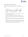
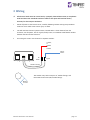
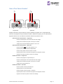
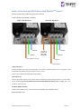
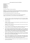
User Manual User Manual and Installation Guide Tornado Moving LightProjector Enclosures Blizzard Enclosures Heater Fan On Relay Temp DMX Lamp ESC OK Tempest Lighting, Inc. 13110 Saticoy Street, Unit C N. Hollywood, CA 91605, USA Tel +1 818 787 8984 Fax +1 818 982 5510 [email protected] For the following products, manufactured after August 2011 Baby Blizzard Blizzard Blizzard Stretch Blizzard X-Stretch www.tempestlighting.com In the interest of continuous product improvement, the information in this document is subject to change without notice. Neither Tempest Lighting, Inc. nor its representatives or agents may be held liable for expense or injury arising from it. © Tempest Lighting Inc. All Rights Reserved Tornado Enclosure User Manual August, 2012 page 1 Table of Contents 1 Introduction ............................................................................................................................. 5 Dimensions ....................................................................................................................... 6 2 Installation ............................................................................................................................... 8 Planning ............................................................................................................................ 9 Mounting .......................................................................................................................... 9 Mounting the Projector in the Blizzard Enclosure .......................................................... 13 3 Wiring..................................................................................................................................... 16 One or Two Power Circuits? ........................................................................................... 17 Indoor Enclosures and HUSH Boxes with MiniDEC TM Control......................................... 18 MiniDEC Operation ......................................................................................................... 19 4 Outdoor Enclosures: Digital Enclosure Control ...................................................................... 20 DEC3.2 Schematic ........................................................................................................... 21 DEC3.2 Main Functions ................................................................................................... 22 Factory Settings – Basic Mode ........................................................................................ 22 Operating Modes ............................................................................................................ 23 DEC3.2 Control Parameters ............................................................................................ 24 DMX Connections ........................................................................................................... 25 DMX Terminations .......................................................................................................... 25 Remote Device Management (RDM) .............................................................................. 26 Power Connections ......................................................................................................... 27 Common Feed operation (factory default) ..................................................................... 28 Split Feed Operation ....................................................................................................... 29 Control Interface ............................................................................................................ 30 RDM Monitoring and Configuration ............................................................................... 33 Firmware Upgrade over RDM ......................................................................................... 34 5 Closing up the Enclosure ........................................................................................................ 35 6 Operation ............................................................................................................................... 36 7 Routine Maintenance............................................................................................................. 37 8 Troubleshooting ..................................................................................................................... 39 9 Limited Warranty ................................................................................................................... 40 Tempest Product Support............................................................................................... 41 Tornado Enclosure User Manual page 2 Declaration of Conformity This is to certify that the following products 6500.IN* Baby Blizzard, force cooled, 230V 6505.IN* Baby Blizzard, force cooled, 230V 6510.IN* Baby Blizzard, DEC3 Enclosure Control, 230V 6515.IN* Baby Blizzard, DEC3 Enclosure Control, 230V 6550.IN* Blizzard, DEC3 Enclosure Control, 230V 6555.IN* Blizzard Stretch, DEC3 Enclosure Control, 230V 6556.IN* Blizzard X-Stretch, DEC3 Enclosure Control, 230V 6560.IN* Blizzard, Force-cooled, 230V 6565.IN* Blizzard Stretch, Force-cooled, 230V 6566.IN* Blizzard X-Stretch, Force-cooled, 230V * Part number may be followed by suffix H, I, or O are in Compliance with the following standards or specifications according to the EMC Directive 89/336/EEC. EN55015, EN61000-3-4, EN61000-3-5, EN61000-4-2, EN61000-4-3, EN61000-4-4, pr EN610004-5, EN61000-4-6, EN61000-4-8, EN61000-4-11 and are in compliance with the following standards or specifications according to the Low Voltage Directive 73/23/EEC. EN60598-1 This declaration is made by the manufacturer Tempest Lighting, Inc. 13110 Saticoy Street, Unit C North Hollywood, CA 91605, USA This declaration is based on tests that were conducted on the submitted samples of the above mentioned products. Detailed results can be referred to test reports CET.TE200909 and LVT.Te200909. Dated: October 26th, 2009 Signature . . . . . . . . . . . . . . Tempest Lighting Inc Tornado Enclosure User Manual page 3 This is to certify that the following products 6500.US Baby Blizzard, force cooled, 230V 6505.US Baby Blizzard, force cooled, 230V 6510.US Baby Blizzard, DEC3 Enclosure Control, 230V 6515.US Baby Blizzard, DEC3 Enclosure Control, 230V 6550.US Blizzard, DEC3 Enclosure Control, 230V 6555.US Blizzard Stretch, DEC3 Enclosure Control, 230V 6556.US Blizzard X-Stretch, DEC3 Enclosure Control, 230V 6560.US Blizzard, Force-cooled, 230V 6565.US Blizzard Stretch, Force-cooled, 230V 6566.US Blizzard X-Stretch, Force-cooled, 230V Have been tested and approved to standards UL 508 (electrical) and UL 50 (environmental), as NEMA 3R enclosures, for use in the United States and Canada. This declaration is made by the manufacturer Tempest Lighting, Inc. 13110 Saticoy Street, Unit C North Hollywood, CA 91605, USA This declaration is based on tests that were conducted on the submitted samples of the above mentioned products. Listing Report No. 3198609LAX-001a refers. Dated: December 12th, 2010 Signature . . . . . . . . . . . . . . Tempest Lighting Inc Tempest Lighting, Inc., 13110 Saticoy Street, North Hollywood, CA 91605, USA www.tempestlighting.com [email protected] t: +1 818 787 8984 f: +1 818 982 5582 Tornado Enclosure User Manual page 4 1 Introduction Products Covered by this Manual 6500 Baby Blizzard, Force-cooled 6505 Baby Blizzard, Force-cooled, Low noise 6510 Baby Blizzard, DEC 3.2 6515 Baby Blizzard, DEC3.2, Low noise 6550 Blizzard, DEC3.2 Enclosure Control 6555 Blizzard Stretch, DEC3.2 Enclosure Control * 6556 Blizzard X-Stretch, DEC3 Enclosure Control * 6560 Blizzard, Force-cooled 6565 Blizzard Stretch, Force-cooled* 6566 Blizzard X-Stretch, Force-cooled* 6590.BK Blizzard Remote Fan/Soundproofing Kit 6590.BK2 Stretch Blizzard Remote Fan/Soundproofing Kit Notes: Part # suffix .US for North American electrical systems Part # suffix .IN for European 230V electrical systems * North American versions are 208VAV as standard. 120VAC available to order Using This Manual Please read this manual in its entirety before starting work. All the information contained is important, and should be read carefully before proceeding. Heed all warnings and advisories. Icon Key: Valuable information Electrical Warning Safety Information Tornado Enclosure User Manual page 5 Dimensions 9” (23cm) 9” (23cm) Baby Blizzard Do not mount in areas shaded gray. ” 12” (30.5cm) 15” (38.1cm) 22” (55.9cm) 26” (66cm) Enclosure Weight: 29lb (13kg) 7” (18cm) 1.2 Maximum Projector Dimensions and Power 17” (43cm) Maximum Projector Power: Tornado Enclosure User Manual 17” (43cm) Standard Versions: 700W Low-Noise Versions: 350W page 6 Blizzard and Stretch Blizzard Maximum Projector Dimensions Model # Description 6550.US Blizzard, DEC3 Enc losure Control, 120V 6550.IN Blizzard, DEC3 Enc losure Control, 230V 6555.US Blizzard S tretc h, DEC3 Enc losure Control, 120V A B C D E F Weight 31"/79c m 33"/84c m 14"/36c m 10"/25c m 24"/61c m 26"/66c m 77lb/35kg 31"/79c m 33"/84c m 14"/36c m 10"/25c m 24"/61c m 26"/66c m 77lb/35kg 41"/104c m 45"/114c m 16"/41c m 12"/30c m 35"/89c m 26"/66c m 97lb/44kg 6555.IN Blizzard S tretc h, DEC3 Enc losure Control, 230V 41"/104c m 45"/114c m 16"/41c m 12"/30c m 35"/89c m 26"/66c m 97lb/44kg 6556.US Blizzard X-S tretc h, DEC3 Enc losure Control, 120V 49"/124c m 51"/130c m 16"/41c m 12"/30c m 42"/107c m 26"/66c m 106lb/48kg 106lb/48kg 6556.IN Blizzard X-S tretc h, DEC3 Enc losure Control, 230V 49"/124c m 51"/130c m 16"/41c m 12"/30c m 42"/107c m 26"/66c m 6560.US Blizzard, Forc e-c ooled, 120V 31"/79c m 33"/84c m 14"/36c m 10"/25c m 24"/61c m 26"/66c m 67lb/30kg 6560.IN Blizzard, Forc e-c ooled, 230V 31"/79c m 33"/84c m 14"/36c m 10"/25c m 24"/61c m 26"/66c m 67lb/30kg 6565.US Blizzard S tretc h, Forc e-c ooled, 120V 41"/104c m 45"/114c m 16"/41c m 12"/30c m 35"/89c m 26"/66c m 87lb/40kg 6565.IN Blizzard S tretc h, Forc e-c ooled, 230V 41"/104c m 45"/114c m 16"/41c m 12"/30c m 35"/89c m 26"/66c m 87lb/40kg 6566.US Blizzard X-S tretc h, Forc e-c ooled, 120V 49"/124c m 51"/130c m 16"/41c m 12"/30c m 42"/107c m 26"/66c m 96lb/47kg 6566.IN Blizzard X-S tretc h, Forc e-c ooled, 230V 49"/124c m 51"/130c m 16"/41c m 12"/30c m 42"/107c m 26"/66c m 96lb/47kg Maximum Projector Lamp Power – 1,300 Watts Note – Draw Latch Clearance Allow adequate clearance for all latches. 3”/75mm Tornado Enclosure User Manual page 7 2 Installation Safety and Warnings These warnings are for your protection. Failure to comply may result in serious injury or death. Tempest Lighting, Inc. assumes no responsibility for damages or injury incurred by misuse or mishandling of product. Do not attempt to install or operate the enclosure before fully reading and understanding this manual Never allow anyone who has not read this manual to open the enclosure or perform maintenance on the projector within. Never leave the enclosure unattended when open. Always make sure all bolts and latches are tight and safety locks are in place after performing any form of maintenance on the unit. Do not open any electrical boxes until power has been shut off to all supply lines to the enclosure (including the one powering the projector). Do not open the enclosure in wet weather. Tornado Enclosure User Manual page 8 Planning Snow clearance: MINIMUM 24”/60cm Allow at least 24”/60cm clearance behind enclosure for access and ventilation. 24”/60cm Enclosures with Digital Enclosure Control MUST be powered 24/7/365. Warning: In most cases this installation cannot be safely completed by 1 person. Mounting The Blizzard enclosure is provided with a pair of Unistrut channels on the enclosure base, for mounting to your structure. You may use standard Unistrut accessories, or purchase mounting kits from Tempest Lighting – four kits are required per enclosure. Each Enclosure must be mounted with FOUR points. All mountings must be made using the two Unistrut channels on the base of the enclosure. Tempest Lighting recommends the use of stainless steel mounting hardware. IMPORTANT SAFETY NOTICE: Installer must ensure that all mounting points are secure and conform to local safety regulations. Tempest Lighting Inc. accepts no responsibility for damage or injury arising from inappropriate or unsafe installation. Tornado Enclosure User Manual page 9 4900.MB Stainless Steel Unistrut channel nut, bolt and washer. Four required per enclosure. 4900.MC Stainless Steel Unistrut channel nut, bolt and pipe clamp, for pipes 1.5” (38mm) to 2” (50mm) OD. Four required per enclosure. 4925.MC Stainless Steel Unistrut channel nut, bolt and pipe clamp, for pipes 2” (50mm) to 2.5” (64mm) OD. Four required per enclosure. Blizzard and Stretch Blizzard Baby Blizzard Suggested layout for mounting plate, using four 4900.MB kits. Suggested layout for mounting plate, using four 4900.MB kits. Side 15.0”/381mm Front/Back Mounting holes 0.532”/13mm, 4 places Mounting holes 0.532”/13mm, 4 places 12.0”/305mm 10.0”/254mm 10.0”/254mm Front/Back Side Mounting plate Guidelines Use ¼” (6mm) or greater aluminum or stainless steel plate. Do not obstruct wiring access. Tornado Enclosure User Manual page 10 2.4 Mounting Base-down and Base-up All Blizzard enclosures are designed to be mounted base-down, on a solid structure, using Unistrut mounting hardware. They may also be suspended from an overhang, ceiling or truss, using the same hardware. Note that in this event it will be necessary to flip the projector image, since the projector itself will be hanging upside-down. It’s important to be sure that the projector to be used supports this feature (usually referred to as Ceiling Mount mode) before commencing installation. Air vents for Base-up operation When the Blizzard is used base-up, remove all air vents, invert, and replace, to prevent rainwater ingress. Air vent, inverted for base-up operation. Tornado Enclosure User Manual page 11 Drainage – Outdoor Enclosures Only Drainage holes are provided in the top and bottom of the Blizzard enclosure. The holes in the cover (top) are plugged with 10-32 screws and sealing washers. Important – Drainage in base-up installations: 1 Remove the drainage plug screws from the cover 2 Replace in the corresponding holes in the base Tornado Enclosure User Manual page 12 Mounting the Projector in the Blizzard Enclosure 1. If the Blizzard enclosure is suspended from a ceiling or overhang, this MUST be done by at least two people. Find the best location for the projector clamp(s), avoiding contact with access doors, vents and control on the projector top. 2. Make sure that all four Projector clamp threaded rods are screwed into the projector tray, and locked in place with the locknut provided. 3. Remove the projector clamp bars. 4. Place the projector on the projector tray. If hanging the projector upside-down, one person must hold the projector in position, while another person secures the projector clamp bars in place. 5. Replace the projector clamp bars and tighen the nuts above and below each end of each projector clamp. DO NOT OVERTIGHTEN. 6. Ensure that the projector is securely held before proceeding further. Note: You can still adjust the projector pan and tilt by loosening the projector clamp, adjusting the projector feet, then re-tightening the projector clamp to hold the projector firmly in place. Note: BABY BLIZZARD is equipped with a load strap to secure the projector in place. Projector Clamp Rubber Pad Threaded Rod Lock Nut Projector Tray 7. Connect the projector power cable to the projector, and plug into the receptacle provided inside the enclosure: Note: International Versions (.IN part # suffix) are equipped with CE17 16amp outlets. US Versions (.US part # suffix) have NEMA L6-20 outlets. Baby Blizzard has an IEC outlet. 8. Connect projector signal cables 9. Tie down any cables away from the exhaust fan 10. Power up the projector, check functions and adjust focus 11. Replace the enclosure cover Tornado Enclosure User Manual page 13 12. Make sure that all latches are securely fastened. The latches are adjustable, and should be checked periodically, since the rubber seal may compress slightly over time. 13. For additional security, use a bolt or padlock to lock one or more of the latches, using the security ring provided. The latch tension is adjusted by turning the screw – clockwise to tension, anti-clockwise to loosen. Tornado Enclosure User Manual Insert a padlock in one or more security rings for additional security. page 14 Blizzard HUSH - Installing the Remote Fan Kit Blizzard HUSH enclosures feature a remote fan that needs to be installed separately. Blizzard HUSH enclosures are equipped with sound insulation inside the enclosure, plus a remote fan kit. 1. Attach a Hose adapter plate to the exhaust air location on the right side of the rear panel, using the four 8-32 screws provided 2. Thread the fan cable through the padded hose provided, using a fish tape 3. Pass the fan cable through the hose adapter, and connect to the FAN terminals inside the enclosure, passing the fan cable through the rubber grommet in the side of the electrical cover. 4. Attach one end of the hose to the hose adapter plate, using one of the clamps provided. 5. Attach the other end to the Fan assembly in the same way, taking care not to crimp the fan cable. 6. Feed the hose through the wall or ceiling to a suitable location and screw in place. This will normally be either in a large ceiling void, or in a remote location with access to outside air. 7. DO NOT EXTEND the hose beyond its 25’/7.6m length. It has been tested at this length, and extending it further may reduce cooling efficacy inside the enclosure. Tornado Enclosure User Manual page 15 3 Wiring All electrical work must be carried out by a properly licensed electrician, in compliance with local electrical standards. Failure to observe this point will void the factory warranty for the Tempest Enclosure. 1 Switch off power to the branch circuit, carefully following lockout and tag-out procedures. Failure to do so could cause serious injury or death. 2 You will need two electrical junction boxes, located within a short distance from the enclosure, one for power, one for signal (usually CAT5). Use outdoor-rated flexible conduit between the box and the enclosure. 3 AC and signal circuits must be wired in separate conduits. 120VAC, or 208VAC or 230VAC Picture Source Heater Fan On Relay Temp DMX Lamp ESC OK AC Power Signal Flexible Conduit The conduit entry holes accept US ½” conduit fittings, and international 20-22mm (OD) conduit fittings. Ø 0.875” 22.2mm Tornado Enclosure User Manual page 16 One or Two Power Circuits? 1 1 2 Single Feed Split Feed Tempest enclosures may be wired on single or double line supplies. On a single feed, both enclosure and projector are permanently on. With a double-line supply, you can switch off the projector when not in use, while the enclosure continues to protect it 24/7. Indoor Enclosures & Hush Boxes – Single Feed Enclosure and Projector must be rated for the same voltage. Supply must be rated for projector current plus 10 watts. Supply may be switched off when projector is not in use. Indoor Enclosures & Hush Boxes – Split Feed Enclosure power must be on when projector is on. Projector power may be switched independently. Enclosure (fan) power must be rated for 10 watts. Projector power must be rated for the projector (see projector manual). Projector and enclosure power must be same voltage. Outdoor Enclosures - Single Feed Enclosure and projector are permanently on. Enclosure and Projector must be rated for the same voltage. Supply must be rated for projector current plus 150 watts. Supply must be permanently ON. Outdoor Enclosures - Split feed Enclosure power must be permanently on. Projector power may be switched off. Enclosure power must be rated for 1150 watts. Projector power must be rated for the projector (see projector manual). Projector and enclosure power must be same voltage. Tornado Enclosure User Manual page 17 Indoor Enclosures and HUSH Boxes with MiniDECTM Control Remove the DEC cover inside the back of the enclosure. Connect AC Wiring to MiniDEC Controller Single Feed Operation Split Feed Operation NEUTRAL GROUND CUT LINK 2 PLACES FOR SPLIT FEED OPERATION LIVE (Projector and Fan) NEUTRAL GROUND LIVE (Fan) LIVE (Projector) Single Feed Wiring Feed the controller with a single maintained supply. The enclosure should be powered 24/7. The projector must be switched off when needed using the projector’s control system. Twister ships configured for single feed wiring operation. Split Feed Wiring You may switch off the supply to the projector without interfering with the cooling fan operation. Connect feeder wires as shown, AND CUT THE COPPER LINK ON THE MiniDEC BOARD IN TWO PLACES, AS SHOWN. Fan circuit should be maintained 24/7. Fan Wire (HUSH versions) Connect the remote fan wire to the terminal marked FAN on the MiniDEC board. Replace MiniDEC Cover Tornado Enclosure User Manual page 18 MiniDEC Operation The MiniDEC controller monitors current going to the projector inside the Blizzard enclosure, and also heat inside the enclosure. When it detects that the projector is on and/or the internal temperature is getting warm, MiniDEC runs the enclosure fan. MiniDEC Operation is completely automatic. Summary: MiniDEC detects current to projector >1.5amps Fan on MiniDEC detects current to projector drop below 1amp 5-minute fan cool-down, then fan off MiniDEC detects temperature 25-35°C (77-95°F) Pulse fan to change air every minute MiniDEC detects temperature >35°C (95°F) Switch Fan on MiniDEC LED Indicator For information and faultfinding there is an LED indicator on the MiniDEC control board. Function as follows: LED OFF: MiniDEC is not powered, or power supply has failed. LED ON: MiniDEC is functioning normally and projector power is < 1amp LED blinking slowly: Projector Power > 1 amp, fan on LED blinking rapidly: Projector power has dropped below 1amp. Fan is running for five minutes for five-minute cool-down Tornado Enclosure User Manual page 19 4 Outdoor Enclosures: Digital Enclosure Control Heater Fan On Relay Temp DMX Lamp ESC OK DEC3.2TM – that’s Digital Enclosure Control, third Generation, revision 2 – is the brain of your Tempest enclosure. It will maintain the internal environment in a comfortable temperature and humidity range, and prevent condensation – the real killer of outdoor equipment. DEC3.2 monitors internal temperature, humidity and lamp current at all times, and uses this information to control the enclosure’s lamp relay, fan(s) and heater(s). It can report back over the DMX cable, using the RDM protocol (Remote Device Management) if desired. Tornado Enclosure User Manual page 20 DEC3.2 Schematic Enclosure Feed (always ON) Split Feed (optional) Cut links for split feed X SENSOR X AC HEATER(S) AC FAN(S) IN OUT IN OUT DMX/RDM – RS485 (OPTIONAL) Tornado Enclosure User Manual page 21 DEC3.2 Main Functions 1 Sense current to projector (lamp on/off) 2 Record lamp hours 3 Monitor temperature and humidity inside Enclosure 4 Maintain temperature at safe operating level 5 Prevent condensation 6 Isolate projector in case of unsafe temperature 7 Report status over RDM 8 (Optional) remote projector relay control over DMX DEC3.2’s function depends on whether the projector lamp is on or off: Lamp ON • Fans on • Heater off • Monitor temperature and humidity • Isolate projector power if temperature exceeds max limit • Record lamp hours Lamp OFF • Monitor temperature and humidity o If temp below bottom setting, run heater o If temp above top setting, run fans o If temp in normal range, run anti-condensation routine Factory Settings – Basic Mode In most applications, DEC3.2 will operate correctly with its factory default settings, in Basic operating mode. You do not need to do anything. Please skip to the Power Connections section below. If your needs are more complex, read on. Tornado Enclosure User Manual page 22 Operating Modes DEC3.2 may operate in one of four modes, set using either the Front Panel or by RDM control. In all configurations, the projector inside the enclosure may also be an RDM enabled device. Basic Mode (factory setting) • Standard temperature settings • DMX and RDM disabled • Best for standalone operation Monitor Mode • As Basic mode, plus: • RDM status reporting • RDM configuration – settings may be changed remotely or at the enclosure control panel • DEC3.2 does not require a DMX signal to operate Control Mode • As Basic mode, plus: • Enclosure functions as a 1-channel DMX device, with remote control of the lamp relay o DMX level > 75% enables normal relay operation (normally ON) o DMX level < 25% disables normal relay operation (relay turns OFF) o This allows you to force a hard reset of the lamp relay in the event of a projector malfunction • Control mode is recommended for show control applications, but can be risky in live show operation. Service Mode • For trained service personnel only • Normal operation is suspended and the enclosure functions as a 3-channel DMX device: • o Lamp Relay o Fans o Heater Service mode is ONLY for troubleshooting – DO NOT use Service mode for normal operation. Tornado Enclosure User Manual page 23 DEC3.2 Control Parameters Temperature Settings: Lamp relay open – Lamp OFF Cutoff Temp Range 0-15°C, Default = 15°C Over-temperature Warning, Fans on Top Set Range 35-45°C, Default = 40°C Normal operation Bottom Set Range 0-10°C, Default = 10°C Under-temperature Warning, Heater on, Fans off Notes: 1 The Cutoff Temperature is an incremental temperature range above the Top Set temperature. So the default 15°C cutoff and 40°C Top Set means that the lamp relay will open when a temperature of 55°C is reached. 2 In moving light enclosures the temperature sensor is located in the exhaust airflow. Temperatures shown may be higher than those around the projector. 3 We recommend using the factory default settings for several weeks or months before making any changes. In most cases they will not be necessary. Humidity Range 50-90%, Default 80% The threshold at which incoming air is more aggressively heated to remove moisture. DMX Address Range 001-510, Default 001 Sets the DMX address for the lamp relay control. Fan Overrun Range 1-15 minutes, Default 5 minutes Time that the enclosure fan(s) will run after the projector/projector lamp is turned off. Temp C/F Display Degrees Celsius or Fahrenheit. Default Celsius Note that temperature settings must always be Celsius. Lamp Hours Default 0000 Counts lamp hours – you must reset to zero when changing lamps. Tornado Enclosure User Manual page 24 DMX Connections DMX refers to USITT DMX512, a commonly used control protocol in the entertainment industry, running over RS485. Consult USITT DMX installation guidelines when laying out a system, or employ a qualified DMX system integrator. A DMX network will be required if: a) The projector inside the enclosure requires a DMX control signal b) You wish to monitor the enclosure using RDM c) You wish to control the enclosure lamp relay over DMX DMX Terminations Note: DMX will not normally be used in projector installations. Pinout: (1) Ground, (2) Data -, (3) Data +. DMX Connectors: ❹ ❸ ❷ ❶ 1 DMX IN from network 2 DMX OUT to projector (or to network if not controlling projector) DMX OUT to next DMX device DMX IN from outside world 3 DMX IN from projector 4 DMX OUT to network If the enclosed projector does not use DMX, then connector (2) on the controller is DMX OUT for the enclosure. DMX Line Terminations DMX cable runs must be terminated at the far end of the cable run with a termination resistor as detailed in the DMX512 standard. DMX terminal Pinout Detail The individual projectors installed inside the Tempest enclosures must NOT be terminated. + ‒ G DMX OUT + ‒ G DMX IN LIGHT + ‒ G DMX OUT LIGHT Tornado Enclosure User Manual + ‒ G DMX IN It is recommended that any line termination is done using the 3-pin terminal connector fitted to the DEC3.2 control circuit board. page 25 Remote Device Management (RDM) RDM refers to ANSI E1.20, a control protocol in the entertainment industry used for device configuration and monitoring, and essentially an “extension” of DMX512. The use of RDM is optional, and uses the same RS485 cable connection as DMX512, so no additional wiring is required. The user must ensure that any DMX splitters or other routing devices used are rated for RDM as well as DMX use. Tempest strongly recommends working with a qualified RDM system integrator when designing an RDM network. Go to www.tempestlighting.com for contact information. RDM and RDM Integration DEC3.2’s RDM implementation allows system integrators to set up remote control and status monitoring of all attributes and sensors, including: • Relative Humidity • Air Temperature • PCB Temperature • Lamp Current • Elapsed Lamp Hours • Lamp Relay Status • Fan Relay Status • Heater Relay Status • DMX Status • DMX Start Address • DMX Personality (RDM Mode) • Device Type • Device Label • Software Version RDM is an effective and powerful tool for commissioning and monitoring an installation, particularly in large systems. For further guidance, please consult a qualified RDM system integrator. Tempest Lighting warrants DEC3.2 to be compliant with the RDM standard, but is not an RDM systems integrator, and can offer only basic guidance on RDM utilization. Tornado Enclosure User Manual page 26 Power Connections IMPORTANT Tempest enclosures are supplied for either 120VAC 50/60Hz, or 208-240VAC, 50/60Hz operation. Tempest Lighting is not liable for damage or failure to operate correctly due to connection to an inappropriate electrical supply. ALL ELECTRICAL CONNECTIONS MUST BE UNDERTAKEN BY A QUALIFIED ELECTRICIAN, IN COMPLIANCE WITH LOCAL NORMS AND STANDARDS. Cut here for split supply operation Fan 1 Projector receptacle Fan 2 Heater(s) Projector Supply (split mode) Enclosure Supply (100-250VAC 50/60Hz) Note: wire colors may differ depending on applicable electrical standards. European wire colors are shown here. IMPORTANT: MAKE SURE THAT TERMINAL SCREWS ARE FULLY BACKED OUT BEFORE INSERTING WIRES. Tornado Enclosure User Manual page 27 Common Feed operation (factory default) 1 Enclosure and projector share the same electrical circuit. Circuit must be powered ON 24/7. Connect incoming power to the terminals labeled MAINS: (E) Earth/Ground (L) Live (N) Neutral E L N Tornado Enclosure User Manual page 28 Split Feed Operation Enclosure and projector have separate electrical feeds. The enclosure circuit must be powered ON 24/7. When splitting the feeders, both circuits should be on the same phase and at the same supply voltage. 1 Use a wire cutter to cut the copper links on the DEC3.2 board in four places. 2 Connect incoming ENCLOSURE power to the terminals labeled MAINS. This supply MUST be maintained 24/7. (E) Earth/Ground 3 E L N Projector Power E L N Enclosure Power Tornado Enclosure User Manual (L) Live (N) Neutral Connect incoming PROJECTOR power to the terminals labeled SPLIT: (E) Earth/Ground (L) Live (N) Neutral page 29 Control Interface LED Indicators Heater SHORT PULSES Lamp is off (green) Temperature is normal Heater is pulsing to prevent condensation ON (Green) Temperature is LOW Heater is ON OFF Lamp is on Temperature is normal Fan PULSES Lamp is off (green) Temperature is normal Fan is moving small amount of air to prevent condensation ON (Green) Lamp is ON, or Temperature is HIGH Fan is cooling enclosure Lamp On ON (Green) Current sensing shows lamp is ON Lamp hour counter is running OFF Current sensing shows lamp is OFF Lamp hour counter is not running Lamp Relay ON (Green) Lamp relay is closed (normal) Projector power receptacle is energized OFF Lamp relay open (due to overtemp or DMX control). Projector is electrically isolated Temp ON (Green) Temperature is in normal range ON (Red) Temperature is above Top setting, or below bottom setting FLASHING (Red) Temperature is above Cutoff level Projector power is isolated DMX OFF DEC3.2 is in BASIC Mode – DMX not used ON (GREEN) Good DMX or RDM data packet received. ON (RED) Control Mode: DMX Fail Monitor Mode: No RDM information being received (this is normal) Tornado Enclosure User Manual page 30 Control Interface Operation The Control Interface is normally LOCKED. To UNLOCK, hold ESC and OK together for 5 seconds. You are now in the CONTROL MENU Use to scroll up and down the menu. Press OK to enter a menu item Use to set the item parameter, or to scroll to the next menu level. Use ESC to go BACK, and OK to confirm settings ( ). To LOCK, hold ESC for 5 seconds. Menu will time out after ten minutes. Control Menu SET DMX ADDRESS (in Monitor, DMX or Service modes) Select a DMX starting address in the range 001 to 510 1 – Lamp Relay In Service Mode an addition two slots are available 2 – Fan Relay 3 – Heater Relay Note that the DMX control is designed using a SAFETY pile-on Logic. So the DMX input can only override automatic settings in a safe manner. SET DMX MODE From the Front Panel, this menu item allows the user to check (and if necessary change) the RDM mode. BASIC Standalone operation, no DMX/RDM (factory default) MONITOR Standalone, plus support for RDM remote configuration and monitoring CONTROL Monitor, plus use of a single DMX address to control Lamp relay SERVICE Monitor, plus use of three DMX slots to control Lamp, heater and fan Important: Please ensure that the DEC3.2 is NOT left in Service Mode. Tornado Enclosure User Manual page 31 STATUS DISPLAY View current status information, using the arrow keys to scroll through: a) Humidity – relative humidity in % b) Firmware version c) Lamp Hours elapsed d) Current being drawn by projector/light projector, in amps e) PCB temperature f) Air temperature, in degrees C or F RESET LAMP HOURS Reset each time you change the lamp in the projector/projector. Make this a part of your maintenance instructions. HUMIDITY SET The humidity level above which the heater kicks in to remove humidity from incoming air (default 80%, permissible range 50-90%). SET FAN OVERRUN Fan will keep running after projector lamp is sensed to change from ON to OFF, to allow the lamp to cool safely. Default is 5 minutes, permissible range 0-15 minutes. SET TEMP RANGES Set three temperature trigger points for Bottom, Top and Cutoff temperatures, in °C. TEMP BOTTOM (default 10°C, permissible range 0-10°C). TEMP TOP (default 40°C, permissible range 35-45°C). TEMP CUTOFF (default 15°C, permissible range 0-15°C). SET TEMP C OR F Choose to display temperature values in Celsius or Fahrenheit (default Celsius) Note that temperature settings must be entered in Celsius. Tornado Enclosure User Manual page 32 RDM Monitoring and Configuration All the features accessible over the DEC3.2 control panel are also available over RDM. Just how this information is displayed will depend on the RDM interface used. These screen shots were taken running the GetSet program in Windows 7, and connecting to a DEC3.2 controller using a RDM TRI MK1 interface, both from JESE Ltd (www.jese.co.uk). This view shows a single DEC3.2 test unit that has been correctly discovered and labeled by the GetSet software suite, and a log of RDM messages. This RDM interface provides a graphic view of the various sensor functions supported by DEC3.2 Important: Check that your RDM interface vendor has tested his interface with Tempest enclosures and all other RDM devices you plan to use on the same network. Tornado Enclosure User Manual page 33 Firmware Upgrade over RDM DEC3.2 firmware is fieldupgradeable, using RDM. A field upgrade requires a JESE RDM TRI MK1 interface to be connected to the DMX network on which the DEC3.2 is located, and the use of JESE GetSet software. Tornado Enclosure User Manual page 34 5 Closing up the Enclosure 1 Check all electrical connections 2 Clear the enclosure and projector of all dust and debris. 3 Check that the power switch on the projector is in the ON position. 4 Complete all signal connections, following projector manufacturer’s instructions. 5 Test projector 6 Tie down cables so that they will not touch heaters or fans. 7 Replace the cover on the Blizzard base. This may require two people. Congratulations! Your system is now ready for use. Tornado Enclosure User Manual page 35 6 Operation Enclosure must receive power at all times. It is an active, climate-controlled enclosure, and will not provide proper protection for the projector inside if it is not connected to AC power. Unless the enclosure or projector is undergoing routine maintenance, the globe should be in place and locked down at all times. Only authorized personnel should open the enclosure (see maintenance warnings in the next section). If the ambient temperature is high enough, the over-temperature shutdown feature may engage and temporarily cut off power to the projector. Once the temperature reaches acceptable levels, power will be automatically restored. Tornado Enclosure User Manual page 36 7 Routine Maintenance It is very important to perform routine maintenance on both the enclosure and the projector within. Failure to do so may reduce lifetime for both the enclosure and the projector. Note Maintenance schedules depend on location and environment. The times given here are general guidelines for you to use. It is up to you to judge whether maintenance should be done more often. We do advise doing these tasks no less often than mentioned here. Safety Although maintenance can be performed while the enclosure is powered, it is safer to carry it out with the power disconnected with proper lockout and tag out procedures followed. Be aware that once the enclosure has had power applied to it, the heater will get hot and the fans will start to turn. Make sure that your hands are clear of these areas before applying power to the enclosure. Only authorized personnel should perform maintenance on the enclosure or projector Do not service the unit in the rain or other adverse weather conditions (snow, sleet, high winds, etc.). Be aware that the cover is a large object that can be awkward to handle, especially when standing on a ladder or scaffolding. Inspection Checklist: - Every Three (3) Months All weep (drain) holes should be clear All vents should be free of debris Enclosure should be free of debris both inside and out Bolts should be tight Lid seal should be in good condition, Check seal inside and out for gaps. Window should not be cracked Fans should be moving (it will be necessary to have the power on to check this), with corresponding indicator status Except for the last two items (concerning globe and fan), problems with any of these things can be easily remedied. Contact technical support for problems with the last two items. Tornado Enclosure User Manual page 37 Air Filters - Every Three (3) Months The air filters should be removed and cleaned on a regular basis. To remove filters, pull them directly out of the cowls. The filters can be cleaned by running water from a hose and do not require any special solution. To reinstall, push filter back into place. Projector Review the manufacturer's instructions for proper maintenance of your projector. Remember, the enclosure simply protects the projector and is not a substitute for regular maintenance. Tornado Enclosure User Manual page 38 8 Troubleshooting This is a guide to the general symptoms, problems, and solutions that may occur during the lifetime of your enclosure. However, it is important to remember that problems may occur within the projector itself and these must also be considered. Projector does not have power. Check power switch of projector. (Note: the following actions should be performed by a licensed electrician) If power is on, check wiring (including metering supply voltages, enclosure must receive 200-240VAC to operate properly). If LEDs on the DEC3 control panel controller are lit, check the Lamp Relay LED. If it is on, meter power in receptacle. If no power is present at the receptacle, contact technical support. In case of over-temperature, the power disconnection is an intended function of the enclosure and is for the protection of the projector, which is not meant to operate in extreme conditions. In this case, the problem will only continue until temperature drops to acceptable levels. It is possible that the air intake or exhaust has become clogged, leading to higher temperatures inside the enclosure. Make sure that these areas are clear, the filters are clean, and the fans are working properly. Projector turns on and off repeatedly Check that vent areas and airways are clear. If so, ambient temperature may be too high (see over-temperature note above) or projector may have internal problem. Fans are not spinning. Fan cords may have become disconnected. Check connections between fan and cord. Fans may be obstructed. Shut off power to enclosure and check for obstructions. Turn power back on to see if fans will start spinning. If fans do not turn and display on temperature controller is lit, contact technical support. If fans do not turn display is not lit, then enclosure is not receiving power. Turn off all power and check wiring. If the wiring is correct, contact technical support. Excessive debris in unit. Filter may not be fully pushed into cowl. Check for gaps. Excessive water in enclosure. Weep (drain) holes may be clogged. Clear them. Latches do not latch properly. Check for obstructions. Tornado Enclosure User Manual page 39 9 Limited Warranty INSPECTION/WARRANTY/RETURNS. A. Customer, at its sole expense, shall inspect all Goods promptly upon receipt and accept all Goods that conform to the specifications or catalog. All claims for any alleged defect in or failure of the Goods or Seller's performance to conform to the Contract, capable of discovery upon reasonable inspection, must be set forth in a written rejection notice detailing the alleged non-conformity, and be received by Seller within thirty (30) calendar days of Customer's receipt of the Goods. Failure by Customer to notify Seller of the alleged nonconformity within thirty (30) days will be conclusive proof that the Goods have been received by Customer without defects or damage, and in the quantities specified on the bill of lading and shall constitute an irrevocable acceptance of the Goods and a waiver of any such claim in connection with the Goods. B. Seller warrants to Customer only that the Goods will be free from defects in material and workmanship at the time of delivery and, subject to the exceptions and conditions set forth below, for the following period (the "Warranty Period"): twelve (12) months from the date of shipment by Seller. Seller may provide additional years of warranty coverage beyond 12 month, at the rate of 2.5% of the net sale price per year, up to a total of four additional years’ coverage beyond the standard 12 month warranty period. Seller will remedy a defect as set forth in paragraph 7 D, below, (the "Warranty"). The Warranty is subject to each of the following exceptions and conditions: 1. Customer must promptly (and in all events within the Warranty Period) notify Seller of any alleged defect in a written notice (the "Notice") which shall set forth the quantity, catalog number, finish, original purchase order number, Seller's invoice number on which Goods were originally billed and a statement of the alleged defect, along with digital photographs showing such defects where feasible. 2. The Warranty shall not apply: (i) to any claimed defect that was capable of discovery upon reasonable inspection and deemed to be waived under paragraph A, above; (ii) to any Goods that have been subject to misuse, abnormal service or handling, or altered or modified in design or construction; (iii) to any Goods repaired or serviced by any person other than Seller's authorized service personnel or to Goods installed other than according to installation instructions, or (iv) with respect to normal wear and tear. 3. Seller makes no Warranty with respect to parts or components that are not the product of Seller, and specifically makes no warranty whatsoever for equipment housed inside enclosure products manufactured by Seller. 4. The Warranty is Seller's exclusive warranty with respect to the Goods. Seller makes no warranties, guarantees or representations, express or implied, to Customer except as set forth in this section. ALL OTHER WARRANTIES, EXPRESS OR IMPLIED, INCLUDING, WITHOUT LIMITATION ANY IMPLIED WARRANTY OF MERCHANTABILITY OR OF FITNESS FOR USE OR FOR A PARTICULAR PURPOSE, ARE HEREBY EXCLUDED AND DISCLAIMED. C. Seller will accept the return of Goods properly rejected under paragraph A, above, or as to which Notice of an alleged breach of Warranty has been timely given and such Goods may be returned to Seller, freight prepaid, but only upon Customer's receipt of Seller's written return material authorization ("RMA") and shipping instructions. The RMA shall be void if the Goods are not received within 45 days after issuance of the RMA. No deduction or credit in respect of any rejected or returned Goods shall be taken until Customer has received Seller's further written deduction or credit/authorization following Seller's inspection to confirm nonconformity or defect. Seller will charge to Customer any and all costs incurred by Seller in connection with the handling, shipping, inspection and disposition of any returned Goods that are determined by Seller not to have been nonconforming upon Delivery or as to which the warranty hereunder is not applicable. D. UPON ANY PROPER RETURN PURSUANT TO PARAGRAPH C, ABOVE, WHETHER IN CONNECTION WITH A REJECTION OF GOODS OR AN ALLEGED BREACH OF WARRANTY AND BASED UPON THE CONDITIONS SET FORTH IN THIS PARAGRAPH 7, SELLER AGREES THAT IT WILL, AS THE SOLE AND EXCLUSIVE REMEDY UNDER THE CONTRACT OR OTHERWISE, FOR ANY NONCONFORMITY OR BREACH OF WARRANTY, AND AT SELLER'S SOLE ELECTION: (i) REPAIR SUCH GOODS; OR (ii) REPLACE SUCH GOODS. Tornado Enclosure User Manual page 40 Tempest Product Support Step 1: First contact your local Dealer for support. Your dealer is best placed to respond quickly to your needs. Step 2: If your dealer is unable to answer your questions please contact Tempest Lighting 13110 Saticoy Street North Hollywood, CA 91605, USA Tel +1 818 787 8984 Fax +1 818 982 5582 [email protected] Visit our web site for current information and specifications: www.tempestlighting.com Tornado Enclosure User Manual page 41