1
User Manual
EtherNet/IP / Modbus TCP Master
Document code: MN67664_ENG
Revision 1.000
Page 14 of 26
Industrial Electronic Devices
SET COMMUNICATION:
This section define the fundamental communication parameters of two buses, EtherNet/IP and
Modbus TCP.
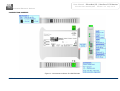
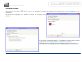
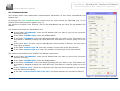
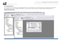
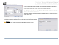
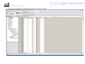
By Pressing the “Set Communication” button from the main window for SW67664 (Fig. 2) the
window “Set Communication” appears (Fig. 3).
The window is divided in two sections, one for the EtherNet/IP and the other for the Modbus TCP
Master.
The means of the fields for “EtherNet/IP” are:
In the fields “IP ADDRESS” insert the IP address that you want to give to the Converter
(EtherNet/IP side);
In the fields “SUBNET Mask” insert the SubNet Mask;
In the fields “GATEWAY” insert the default gateway that you want to use. This feature can
be enabled or disabled pressing the Check Box field. This feature is used for going out of the
net;
In the field “Port” the port used for EtherNet/IP communication is defined. The port has a
fixed value of 44818;
In the fields “Number Byte IN” insert the number of input byte of the slave station;
In the fields “Number Byte Out” insert the number of output byte of the slave station.
The means of the fields for the “Modbus TCP Master” section are:
In the fields “IP ADDRESS” insert the IP address that you want to give to the Converter
(Modbus TCP side);
In the fields “SUBNET Mask” insert the SubNet Mask;
In the fields “GATEWAY” insert the default gateway that you want to use. This feature can
be enabled or disabled pressing the Check Box field. This feature is used for going out of the
net;
In the “TimeOut (ms)” define the maximum time that the device attends for the answer
from the slave interrogated;
In the field “Communication Idle Time (ms)” the delay between two requests is defined.
Figure 3: “Set Communication” window
ADFweb.com S.r.l.