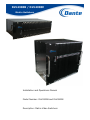
1
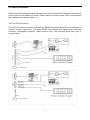
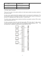
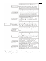
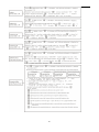
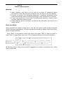
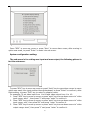
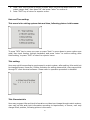
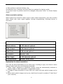
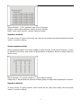
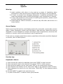
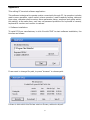
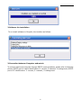
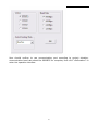
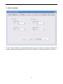
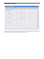
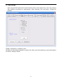
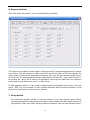
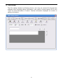
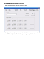
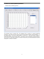
DLV4300B / DLV4900E
Matrix Switchers
Installation and Operations Manual
Model Number: DLV4300B and DLV4900E
Description: Matrix Video Switchers
Important Safety Introductions
Please read the following content before user installs our products.
Only qualified technician or installer should attempt the installation of this
unit.
1.
.Do not block or cover the ventilation openings in the enclosure.
Place the unit at least 2 inches/5cm away from the wall to prevent it from overheating.
2.
.Do not drop metallic parts into the ventilation openings.
Dropping parts will lead to unit malfunction. If this does happen, switch off the power
and notify qualified engineer to service the unit.
3.
.Do not open or remove covers with power on.
Opening or removing covers may expose user to dangerous voltage or other hazards.
There is no user serviceable part. Only qualified engineer may service the unit.
4.
.Handle with care.
Avoid excessive force or vibration to the unit, which will cause damage to it.
5.
.Keep the unit away from water or moisture.
Do not operate the unit near a wet location. If entered water or moisture cause
malfunction of the unit, switch off the power and notify qualified engineer to service
the unit. Water or moisture may damage the unit that may also expose user to
dangerous electric shock.
6.
.Do not use strong or abrasive detergent to clean the unit.
Use a dry soft cloth to clean the unit and remove any dust on it. Use neutral detergent
to clean the unit carefully when necessary. Operate the unit within the required
temperature, humidity ranges and under required power supply conditions.
7.
.Do not operate the unit in high temperature or humidity conditions.
The operating environment ranges are: Temperature : -0℃~+40℃, humidity <90%.
Responsibility
Regards to product warranty, should the following happen, user is responsible:
1. Physical damage the products directly or indirectly
2. User operate the products improperly and cause a personnel injury and damage by the
negligence
3. User who is unauthorized by company to disassemble, maintain or modify the products
personally;
4. Due to miss match with third-party system resulting in problems, loss or injury.
2
Content
Part I
Matrix system Introduction-------------------------------------------------------------------------------------------------------5
Introduction----------------------------------------------------------------------------------------------------------------------------5
System Function---------------------------------------------------------------------------------------------------------------------6
Part II
Matrix Components------------------------------------------------------------------------------------------------------------------8
Power Module--------------------------------------------------------------------------------------------------------------------------8
CPU----------------------------------------------------------------------------------------------------------------------------------------8
Video Input Module-------------------------------------------------------------------------------------------------------------------8
Video Output Module----------------------------------------------------------------------------------------------------------------10
Protocol Module----------------------------------------------------------------------------------------------------------------------11
Case Size--------------------------------------------------------------------------------------------------------------------------------11
Part III
Installation and Connection-------------------------------------------------------------------------------------------------------13
System Installation------------------------------------------------------------------------------------------------------------------ 13
Case Components--------------------------------------------------------------------------------------------------------------------13
Power Connections------------------------------------------------------------------------------------------------------------------14
CPU Connection----------------------------------------------------------------------------------------------------------------------14
Video Input Module Connection--------------------------------------------------------------------------------------------------15
Video Output Module Connection------------------------------------------------------------------------------------------------16
Part IV
System Operation---------------------------------------------------------------------------------------------------------------------17
System Keyboard---------------------------------------------------------------------------------------------------------------------17
Monitor Display------------------------------------------------------------------------------------------------------------------------21
Keyboard Login------------------------------------------------------------------------------------------------------------------------21
Video Input or output through Keyboard--------------------------------------------------------------------------------------21
Set Up preset displayed on keyboard--------------------------------------------------------------------------------21
3
Set Up Monitor displayed on keyboard------------------------------------------------------------------------------21
Switch camera into monitor---------------------------------------------------------------------------------------------22
Control front equipment -------------------------------------------------------------------------------------------------23
Control Pan/Tilt through Keyboard-----------------------------------------------------------------------------------23
Control Camera--------------------------------------------------------------------------------------------------------------23
Set Up preset-----------------------------------------------------------------------------------------------------------------24
Control Auxiliary------------------------------------------------------------------------------------------------------------24
Run auto Switch Group--------------------------------------------------------------------------------------------------------------24
Set Up system Synchronous Switch--------------------------------------------------------------------------------------------24
Alarm Confirmation(Clear)----------------------------------------------------------------------------------------------------------25
Part V
Matrix Menu Program----------------------------------------------------------------------------------------------------------------26
Enter into Menu------------------------------------------------------------------------------------------------------------------------26
System Deploy setting---------------------------------------------------------------------------------------------------------------27
Date and Time setting----------------------------------------------------------------------------------------------------------------28
Character Setting----------------------------------------------------------------------------------------------------------------------28
Character Display----------------------------------------------------------------------------------------------------------------------28
Alarm Association Setting----------------------------------------------------------------------------------------------------------29
Sequence Switch-----------------------------------------------------------------------------------------------------------------------30
Groups Switch---------------------------------------------------------------------------------------------------------------------------30
Group switch by order----------------------------------------------------------------------------------------------------------------31
Alarm recording inquiry--------------------------------------------------------------------------------------------------------------32
Default setting---------------------------------------------------------------------------------------------------------------------------32
Part VI
Appendix-----------------------------------------------------------------------------------------------------------------------------------33
Appendix A LCD display/Special Function key-------------------------------------------------------------------------------33
Appendix B Title PC terminal software application--------------------------------------------------------------------------35
Appendix C Equipment extended and application---------------------------------------------------------------------------50
Appendix D Typical Diagram---------------------------------------------------------------------------------------------------------52
4
Part I
Matrix System Introduction
Warning:
1) matrix switcher with alarm is only used as a means of interfacing alarm
equipment to other devices such as Digital Video Recorder to call out cameras.
2) In order to prevent from damaging equipment, a qualified professional must
install and maintain matrix switcher according to user introductions in manual.
3) If user meet problems in the process of installing and operation, please consult
re-seller technology service center.
4) Please keep bar code of enclosure, so that we may offer after sale service on a
timely fashion.
Introduction:
Matrix system is CCTV surveillance system, which has multi-channel video input, video
outputs and multi-control terminal. Standard units may control up to 1024 video inputs and
128 video outputs (higher input/outputs available). Video input can connect to front
cameras and video output can connect to monitor, or connect to DVR for recording.
Matrix system can switch max up to 1024 channels video input signal to 128 video
outputs, and it can work with multiple keyboards or computer, user may operate pan/ tilt or
camera through keyboard.
In order to add video switch function, matrix system has alarm and auxiliary switcher
control function to control light and switcher…etc. matrix adopts plug in and plug out PCB
design, including power PCB, CPU PCB, Data PCB, video loss inspection PCB, video input
PCB , video output PCB. Matrix is extended to add video input and video output quantity.
Externally connected equipment, such as keyboard, receiver/driver, auxiliary follower,
are connected to matrix system through multi-protocol, including RS232, RS485. System is
controlled by CPU PCB or multiple keyboards.
Switcher Case:
All PCB of matrix is set up before leaving factory, so basically, user doesn’t need to set up
it again, if user change PCB or system deploy is changed, user need to resume it. All
switchers are on printed PCB of PCB, it can be adjusted until all PCBs are moved out from
case, but for some operations, user don’t need to pull out PCB, such as title, display position,
light adjust.
Inner Switcher:
All PCB of matrix are set up before leaving factory, so basically, user doesn’t need to set
up again. If user change PCB or system configuration is changed, user need to resume it.
All switchers cards are adjustable until PCBs are removed from the enclosure, but for some
operations, user don’t need to pull out PCB, such as title, display position, light adjust.
5
System Function:
Menu Operation:
User may program matrix system through Keyboard and monitor. Program menu would
be displayed on Monitor, LCD menu will offer following function: system status display,
system setting save or Set up.
Video Switch:
Matrix can switch any camera video signal to any monitor, user may set camera preset
through matrix, user may Set up any presets on any monitors, switch is operated by
manual or system auto switch, synchronous switch, alarm switch and timed set up presets.
Auto Switch Queue:
Auto switch is to display a groups of cameras circularly on signal monitor, user may set up
different time for every image, moreover, one camera’s image would be displayed
repeatedly, switch would be operated by order, switch group has monitor switch Queue and
system switch Queue.
Monitor Switch Queue:
User may program one group of camera images to be displayed circularly on one
monitor, it is consist of 64 camera signals, every image may be set for different dwell time,
every monitor has separate switch queue.
System Switch Queue:
User may program system switch queue through system menu, Operator may Set up
64 units switch queue at will to any monitor to display, every switch queue is consist of
cameras, presets, dwell time, auxiliary function, in one switch queue, the same image or
camera’s multi-preset or assistant function would appear several times.
System Synchronous Switch:
System synchronous switch is to switch one group of image by order to one group of
continuous monitor to be displayed. There are 64 units system synchronous switch
programmed through system setting menu, every system synchronous switch is consist of
multi-cameras, presets, dwell time and auxiliary function.
Alarm Program:
Multi-unit consisted of 64 channel input alarm port may connect to system through RS-485
port, so that system may be extended to max 1024 channels alarm input. Every alarm
input can Set up any camera’s image or any group camera to any monitor through
programming.
Camera title:
User may program camera title on monitor, for every camera, user may input max 10
character, time, date, camera S/N, camera and monitor status, and camera’ title would be
displayed on monitor, in addition, title position is programmed on any corner of monitor.
6
RS-232/485 Communication Port:
Matrix system offer one RS-232 port which is used as I/O port. Matrix system offers 3
RS-485 ports which connect to keyboard, PTZ camera and audio matrix.
Receiver/driver Control
The matrix switcher control P/T, lens, speed dome, and alternate function by
receiver/driver which is built in the case. One camera can have 128 presets by program at
most. To control the P/T ‘speed. The receiver/driver build in muti-protocol, such as Pelco-D,
Pelco-P etc., Baud rate 1200, 2400, 4800, 9600 for options.
PC Control
By using the PC operating system which is supported by Windows OS, running graphical
interfaces software, to achieve matrix system operation and programming on the basis of
electronic map and equipments.
Graphical interfaces software may display muti-electronic map, all PTZ , camera , monitor,
alarming contacts, auxiliary switch etc. Which will display on the map by icon. After setup
the icon’s parameters, use may click the icon to achieve camera switch and control by
mouse, The function Virtual Keyboard can set and program the system. The alarm contacts’
status will displays on alarm icon, and linkage image switch and auxiliary switch when
alarm contacts.
Innovative input identification
User may Improve the camera title’s overlay Settings by our special application software.
Overlay can be image, image-text and restricted title.etc.
Power-off protection function
The matrix switcher with memory store when power off. Automatic recover the working
position when reboot computer. Such as the image display on monitor( camera number,
group switching, time sequence switching etc.)
Date Storage
After system is out of power, All data in the storage is saved at least five years by battery.
Such as data include the screen character denotation, switch data, alarm data, time and
date etc.
Password Login
User input 6688 number, then press “enter” to logon in or logon out.
7
Operation Authorities
The keyboard system provide operator password login function. User has to login with
right password, and then enable to control the system. Password login may be set up to
16 different users. When the keyboard with password login function control matrix
switcher , the password of the matrix should cancel.
Multistage Control
The keyboard admits setting different operation authorities on the basis of different users
and to limit the menu setup by non-user.
Part II
Matrix System Components
Warning:
1) matrix switcher with alarm is only used as assistant alarm equipment, it is not
used as professional alarm equipment.
2) In order to prevent from damaging equipment, It is professional worker who
install and maintain matrix switcher according to using introduction.
3) If user meet problems in the process of installing and using, please consult to
technology service center.
4) To keep bar code of case very well, so that we may offer our after sale service
in time.
2.1 Power Module
110VAC and 220VAC are DIP Switch selectable by User. See the pictures as follows,
2.2 CPU module
Matrix main module control the whole system, remote controlled PTZ and the lens of the
camera, and also offer the programmed menu which used to establish the system.
8
The back panel of the matrix (see the image) offer the different communicate ports of the
keyboard, digital receiver/driver, alarm and so on.
Matrix system receives the input signals of keyboard, PC and Alarm via the control port.
Different dimension matrix have different CPU, More specs, please see the pictures as
below,
2.3 Video Input Module(
(VIM)
)
The connection should be finished before the power is on.
All video input (such as cameras) should be connected to the BNC of video input module
(VIM); all video output (for example, monitors) should be connected to the BNC of the
video output module (VOM).
Note: All video cables should be used with high-quality BNC plug, (3U matrix switcher with
DB15 port),75Ω video cable. Video output has to connect the 75Ω load terminal.
Intermediate unit must be set to high resistance. If use does not take the load, the image
will be too bright. On the other hand, if use take the two times load; the image will be too
dark.
9
2.4 Video Output Module(
(VOM)
)
The connection should be finish before the power is on.
Note: All video links should be used with high-quality BNC plug, (3U matrix switcher with
DB15 port),75Ω video cable. Video output has to connect the 75Ω load terminal.
Intermediate unit must be set to high resistance. If use do not take the load, the image will
be too bright. On the other hand, if use take the two times load; the image will be too dark
10
2.5 Protocol Module
Matrix system built in muti-protocol module, user may set the matrix switcher’s control
protocol and communication rate. ( the factory standard is Pelco-D, communication rate is
2400Bit/s). The matrix switcher of operation method as follows,
3U matrix switcher : Turn on the two screws on the left of the case with three LED, then
use will see the PCB board, as below,
9U matrix switcher : Turn on the four screws on the left of the case with eight LED, then
use will see the PCB board , as below,
Switcher for Protocol and communication rate setting
Protocol
BIT1
BIT2
Baud Rate
BIT3
BIT4
Pelco-D
Pelco-P
Kalatel
Factory
OFF
ON
OFF
ON
OFF
OFF
ON
ON
9600BIT/S
4800BIT/S
2400BIT/S
1200BIT/S
OFF
ON
OFF
ON
OFF
OFF
ON
ON
2.6
Matrix Case
There are four kinds of matrix switcher for options; 3U standard case, 9U standard case, as
below:
11
12
Part III
Matrix Installation and Connection
Warning:
1) matrix switcher with alarm is only used as a means of interfacing alarm
equipment to other devices such as Digital Video Recorder to call out cameras.
2) In order to prevent from damaging equipment, a qualified professional must
install and maintain matrix switcher according to user introductions in manual.
3) If user meet problems in the process of installing and operation, please consult
re-seller technology service center.
4) Please keep bar code of enclosure, so that we may offer after sale service on a
timely fashion.
System Installation
It is person who is professional in Matrix can install matrix, and comply with relative rules,
in order to prevent from damaging matrix, before installation, please check equipment
carefully.
3.1 The Parts of Case
User manual
Standard case with all the modules use need
Power cords which accord with local standard requirements.
One RS-232 communication Cable
Client software
3.2 Equipment Installation
Firstly, please make a plan and form before connecting for ensure the installation
successfully.
Secondly, Record the process of installation for easy system maintenance and updating.
Such as,
the video input No. and where it is.
The color and spec of the cables and connecting lines.
The warning message of installation
The entire recorded text of the process of installation.
The main case should be fix on the standard cabinet with 19 inch(ETA). Keep the case and
environment ‘s distance with one meter at lease for easy operation and good ventilation.
13
3.3 Power Connection
When all system module and external equipment are connected well, please connect the AC
power line and the module of power, Please make sure input power which is accordance
with default power before power on.
3.4 CPU PCB Connection
The CPM of the matrix switcher provide three RS485 port which are used for connecting the
system’s control equipment. The three RS485 port receive the signals from keyboard
controller, multimedia computer, alarm extend case. The following show user how to
connect them.
14
3.5 Video Input Connection
There are two styles of matrix switchers, all video input modules have been installed in the
cases by order.
All video input modules should be installed in order for convenience of maintenance. The
first camera should be connected to the BNC of video input module, which is on the left of
the case. (3U standard case is BNC port with “1”) and so forth.
1. Video input connection
All video links should be used with high-quality BNC plug, all video cable with 75Ω. The
video cable should be high quality. All BNC port should be mark by order.
2. The requirements of Video cable
The video signal will decay by the transmission distance. so please select the accurate video
cable on the basis of transmission distance. The comparison table as follows ,
Video cable spec and transmit distance
Video cable spec
Transmit distance
75-2
About 150 M
75-3
About 200M
75-4
About 270 M
15
75-5
About 370 M
75-7
About 500 M
75-9
About 680 M
3.6 Video output Connection
There are four styles of the matrix switcher, all video input modules have been installed in
the case by order.
All video input modules should be installed in order for convenience of maintenance. The
first camera should be connected to the BNC of video input module, which is on the left of
the case. (3U standard case is BNC port with “1”) and so forth
The video output module of matrix switcher should be connected to monitor, VCR or other
video equipments with 75Ω.
All video connection should be used with high-quality 75Ω video cable. If video output
connect with muti-equipments, please switch the impedance switching tube to “HiZ”, the
last equipment’s impedance switching tube should be set by 75Ω.
16
Part IV
Matrix Switcher Operation
Warning:
1) matrix switcher with alarm is only used as a means of interfacing alarm
equipment to other devices such as Digital Video Recorder to call out cameras.
2) In order to prevent from damaging equipment, a qualified professional must
install and maintain matrix switcher according to user introductions in manual.
3) If user meet problems in the process of installing and operation, please consult
re-seller technology service center.
4) Please keep bar code of enclosure, so that we may offer after sale service on a
timely fashion.
System Operation
System Keyboard
User may operate and set matrix switcher through Keyboard with RS485 port and
Multimedia management software. Because keyboard and management software have
many kind of version, their function is different, herein we mainly introduce how to operate
matrix switcher through keyboard, how to operate matrix switcher through other
equipments, please refer to user manual.
User will use full function keyboard to operate matrix switcher, system setup includes
non-menu setting and menu programming, in order to protect setting information, user
need to long in keyboard to set information through password, max up to 16 users are
permitted to set password with 4 number for each keyboard, different user has different
operation limitation, different user may set relative function and program menu according
priority.
OSD of keyboard
To press ”menu” to enter into keyboard’s OSD ( speed dome setting, keyboard setting,
assistant switcher setting (rain brusher) assistant switcher setting(heat),assistant No.1
switcher, assistant No.2 switcher, Matrix menu operation, joystick setting),at the same time,
user may press “MPX” to page up and down menu or press “auto” to page up and down
menu.
Speed dome setting menu:
To press “MPX” to page up and down or press “auto” to page up and down menu until user
may see following menu on LCD of keyboard.
17
Keyboard setting Menu
To press “MPX” to page up and down or press “auto” to page up and down menu until user
may see following menu on LCD:
18
Other function setting menu for keyboard
To press “MPX” to page up and down or press “auto” to page up and down menu until user
may see following menu on LCD:
19
20
Monitor screen display:
Matrix system is characterized with screen title display, there are monitor number,
camera ID, camera title, monitor status, date and time (alarm information, switch time or
status information) displayed on monitor, these title is displayed or is not displayed on
screen according to requirement, even user may set position where title is located on
screen.
Title position would be changed according to signal system, title position in PAL
system is lower than that in NTSC, If screen title has been open, but user may see title
displayed on screen, please check whether signal system setting is accordance with video
input/output signal system or not.
Displayed content on screen may be changed through non-menu setting, user may
adjust monitor display parameters, these parameters can be opened or closed though
menu.
Keyboard Login
When operator need to lock keyboard, press “login” key to enter into user management
menu, at this time, LCD information as follows.
At the same time, user may input password, then press “enter” to lock and unlock
keyboard ( password 6688)
Choose video input/output through keyboard
To Set up video Image
The procedure are following:
1) To press “ clear” to clear screen number .
2) Input monitored position number to Set up image, the number would be displayed on
LCD of keyboard, please refer to following picture:
21
For example: To Set up number 2 monitor position
1) Press “clear” key.
2) Press number 2 key; at this time, this position is the place which is being monitored.
To Set up Monitor
The procedures are following:
1) To press “clear” to clear screen number.
2) To input monitor S/N, the number would be displayed on LCD
3) To press “MON” to clear number of MON, then input number of monitor client need,
please refer to following pictures.
For example: To Set up No.2 monitor
1) press “clear” key.
2) press “2” key
3) Press “MON” key
At this time,NO.2 monitor is the one which is being monitored.
To switch one image into monitor
The procedures are following:
1) To press “clear” to clear number
2) To input camera’s S/N, the number would be displayed on LCD.
3) To press “CAM” key, Image would be displayed on monitor, moreover, would display
camera title and No.
Refer to following picture:
For example: To Set up N0.8 camera
1) To press ”clear” key
2) To press number 8
3) To press “CAM” key.
At this time, No.8 camera is the one which is being monitored.
22
Front end equipment control:
To control P/T, Lens, Presets and other function of dome camera is valid until dome is
displayed up on monitor .
Joystick Operation:
The joystick of keyboard controls P/T, when joystick is moved to right, the dome also moves
to right, when joystick is moved to left, the dome also moves to left.
When user controls changed speed P/T, the speed of dome depends on joystick’s movement,
if user moves joystick slightly to right, the speed of dome would be slow, user continues to
move joystick to right powerfully, the dome would speed up. When joystick return to center,
the dome would stop moving. If user move joystick diagonally, P/T would move horizontally
and vertically, moreover moving direction is the same with joystick’s direction. User may
also move slowly joystick diagonally, dome would move slowly to right up.
Priority:
When several keyboards control the same address code of dome in matrix system at the
same time, system will carry out priority rule to avoid operation interference, namely, the
first control keyboard has priority to control dome, other keyboards can’t operate front
equipment (receiver/driver or speed dome ), when priority keyboard doesn’t control front
equipments within 2 seconds, other keyboard can control this equipment.
Lens Control:
The key of lens control on keyboard control receiver/driver and speed dome’s camera, the
operation is the same with joystick operation, lens control also priority.
Zoom in and zoom out:
The camera zoom in and zoom out to get near image and far image. When user press
“Zoom Tele” to get near image, the objective would be magnified on monitor, when user
press “zoom wide” to get far image, the objective would be smaller on monitor, objective
magnified or reduced depends on time of pressing key, if user use 3 axis keyboard, user
may zoom in and zoom out through joystick, if user rotate joystick clockwise, objective
would zoom out, if user rotate joystick counter clockwise, objective would zoom in.
Focus:
When user press “Focus Far” key, far objective would be clear, near objective would be
unclear. If user press” Focus Near” key, near objective would be clear, far objective would
be unclear or out of focus.
Control Iris:
Generally speaking, camera’s Iris auto adjust image brightness, however, sometimes user
need to adjust image brightness manually. There are two keys which can adjust light going
into camera, if user need to make image bright, need to press “Iris Open” key, if user want
to make image dark, need to press “Iris Close” key.
23
To Set Up preset:
Preset is a scene set in advance, whatever position camera is on, when user Sets up presets,
speed dome or receiver/driver will move to preset position, at the same time, camera lens
also auto adjust image size, preset image would be displayed on screen automatically,
matrix system supports max 128 presets.
As a result of mechanism structure, speed dome camera can Set up preset quickly, but P/T
only move to preset position slowly according to P/T speed.
“Call” key on keyboard can Set up preset, the operation procedure are following:
1) Set up camera which user need on monitor;
2)Input preset number( 1-128 )
3) press “call” key to Set up preset
Assistant Switcher Control:
“F1/On” or “F2/On” on keyboard is to control assistant switcher, receiver/driver, speed
dome… in matrix system, please refer to user manual for switchers in detailed
The procedure are following:
1) Set up camera which user need on monitor
2) input switcher number through keyboard
3) Press F1/On key, assistant switcher would be open.
4) Press F2/OFF key, assistant switcher would be closed.
Run auto switch group images:
When user operation this function, a series of set images would be displayed on one
monitor continuously, user not only set signal monitor to switch a group of images in matrix
system, but also user may set many monitors to switch a group of images.
The pre-condition for this operation is that switched images on appointed monitor must be
set. To press “SEQ” key, a group of images would be switched automatically according to
program.
1. To input switching group number 1-32 though keyboard.
2. To press “SEQ” key to carry out operation
3. If user want to stop it, press “shift+SEQ” key.
Set Up Synchronous Switch:
To Set up synchronous switch is to switch a group of images on a group of monitor one by
one, user may set synchronous switch though menu.
The procedures are following:
1) Input synchronous switch number 1-16 through keyboard.
2) Press “GRP” key to carry out this operation.
3) If user want to stop it, press “shift+GRP” key.
24
Alarm Confirm / Clear:
:
Once system send alarm signal, image would be displayed on monitor, and alarm
information would also be displayed on monitor. If this alarm spot need to be cleared
manually, user need to input command through keyboard to clear it.
Alarm operation:
1. Alarm arming: input alarm spot number (0-1024), press “enable” to arm alarm;
2. Alarm disarming: input alarm spot number (0-1024), press “shift+enable” key to
disarm alarm;
3. Alarm Inquiry: Input alarm spot number (0-1024), press ”ack”key to inquiry alarm
spot’s arming/disarming, “A-ON” is for alarm arming,” A-OFF” is for alarm disarming.
4. Clear alarm: press “shift+clear” key to clear alarm.
25
Part V
Matrix menu program
Warning:
1) matrix switcher with alarm is only used as a means of interfacing alarm
equipment to other devices such as Digital Video Recorder to call out cameras.
2) In order to prevent from damaging equipment, a qualified professional must
install and maintain matrix switcher according to user introductions in manual.
3) If user meet problems in the process of installing and operation, please consult
re-seller technology service center.
4) Please keep bar code of enclosure, so that we may offer after sale service on a
timely fashion.
Enter into Menu:
Matrix switcher has system setting menu, user may set system menu through keyboard
and PC client terminal software, let’s set keyboard for example to explain how to set system
menu through keyboard.
Press “Menu” on keyboard to enter into menu, then press ”MPX” to page up menu or
press ”Auto” to page down menu until LCD of keyboard displays following information.
At this time, matrix setting menu would be appeared on monitor connected to No.1 video
output, as follows.
26
Press ”MPX” to move up cursor or press “Auto” to move down cursor, after moving to
option user need, to press” Enter” to enter into sub-menu.
System configuration setting:
The sub-menu is for setting max input and max output, the following picture is
for this sub-menu.
To press "MPX” key to move up cursor or press” Auto” key to move down cursor to menu
option user need, then input number through keyboard, to press” Enter” to confirm it, after
finish setting, to press ”DVR” key to return to superior menu.
For example: To set video input from 1 to 64 and video output from 1 to 16:
1. Press” MPX” key to move up cursor or press” auto” key to move down cursor to” video
input range: start” , then press”1” and press “enter” to confirm it.
2. Press "MPX” key to move up cursor or press "auto” key to move down cursor to” video
input range: end”, then press”64” and press “enter” to confirm it.
3. Press "MPX” key to move up cursor or press "auto” key to move down cursor to” video
output range: start”, then press”1” and press “enter” to confirm it.
27
4. Press "MPX” key to move up cursor or press "auto” key to move down cursor to” video
output range: end”, then press”16” and press “enter” to confirm it.
5. Press “DVR” key to return to superior menu.
Date and Time setting:
This menu is for setting system date and time, following picture is this menu:
To press “MPX” key to move up cursor or press “Auto” to move down to menu option user
need, then input number through keyboard, and press "enter” to confirm setting, after
finish setting, to press “DVR” to return to superior menu.
Title setting:
User may set title according to requirement in matrix system, after setting, title would not
be changed forever, there are 12 letter limitation for setting camera title, user may set title
through PC client terminal software. Please refer to operation procedure in detailed.
Title Characteristic:
User may program title and clock information on video input image through matrix system,
user may set title and clock information according to requirement, of course, user may
change title’s position, following picture is the menu:
28
1) Title position is optional: bottom, top;
2) Character, time, character and time, blank are optional for display model;
3) To move cursor to position need to be changed, then press “enter” to choose display
model.
Alarm association setting:
Matrix system can connect to alarm input or alarm output equipments, user may combine
alarm signal with video signal together through programming, following picture is
sub-menu.
All data choose range:
Alarm address:
1-128 channel optional
Video Output:
1-16 channel optional
Dwell time:
1-99 second optional
Association
Invalid, valid
Video Input:
Arming Method:
1-128 channels optional
Manual, timed, often
Explanation for alarm association:
User may set alarm association for any alarm spot, if setting is right, once there is alarm
happen, matrix will carry out following commands:
1) “Video image” displayed on appointed monitor would be automatically switched to
display image of video association on appointed monitor.
2) If image of video association is more than one, matrix will auto switch images one by
one.
3) When matrix switch images one by one, dwell time for each is number of “dwell time”
(unit: second)
29
Warnings in the process of setting:
1)User set all data through keyboard, then press “enter” to confirm it.
2)If camera of “video association” is less than 5 pieces, please fill “0” in redundant S/N of
video association.
3)Regarding character modification, after modifying character, user press "enter” to
confirm it directly.
4)When arming method is timed, arming time and disarming time is helpful.
5)When arming method is “Normal Open”, the relative alarm equipments will work day
and night, any other equipments can’t control its arming and disarming.
Sequence switch setting:
:
Matrix switcher can switch all video images automatically on monitor through programming,
following picture is sequence switch sub-menu:
Warning:
There are max 32 groups of sequence switch menu in matrix system, switch input signal
max up to 32 channel for each group, number left “=” is S/N in above picture, it shows
image order, number right “=” is video input signal ID, user may choose number from 1 to
96 at will.
User may choose dwell time from 1 to 99 second, user may set dwell time of image
displayed on monitor.
Please pay attention to following points when user set information:
1) user may choose video input channels from 1 to 32,
2) each group of sequence switch has max 32 images, if user choose less than 32 number,
take 16 for example, user need to move cursor to 17 to input “0”, then press “enter”
to make sure all number is 0 after number 17.
Group switch setting:
User may switch appointed image on a group of monitor through group switch at the same
time, user only press one key to carry out this operation any time, this sub-menu offer 16
groups of program solution, please refer to following sub-menu.
30
Group Number: 1-16 is optional, max up to 16 groups.
Output: video output channel, namely monitor number.
Input: video input channel, namely camera number.
Operation method:
To move cursor to option need to be set, then input number through keyboard and press
“enter” to confirm setting.
Group sequence switch:
Group sequence switch is to switch image on many monitor at set time at interval, in order
to realize this function, user must set group switch in advance. Below is group sequence
switch menu.
Group Number: it is group number in “ group switch setting”.
Delay time: 1-99 seconds are optional for each group of images were displayed on monitor.
Operation Method:
To move cursor to group number which would be set, then input delay time and press
“enter” to confirm setting.
31
Alarm record inquiry:
Matrix switcher has alarm recording function, when alarm happens, matrix can record
alarm time and date according alarm order, save max 100 latest recording. Below is alarm
record inquiry menu.
S/N: alarm record S/N
Alarm No.: alarm address
Alarm time: it means
( month-day-hour-minute)
alarm
time,
recording
format
is
MM-DD,
HH:
MM
Warning:
1) Matrix system can record 10 alarm info on one page, total is 10 pages.
2) To move cursor to “clear”, to press “enter” to clear all alarm recording.
3) Alarm recording couldn’t be saved after power is off.
Default setting:
There are Initialization setting for system menu before all matrix was sent out . when user
moves cursor to main menu” default setting”, and press “enter” key, and cursor would stop
displaying on screen, initialization process will take about 90 seconds, then screen would
automatically return to status of power is on, initialization setting is finished.
Default setting are following:
1. Input range: start=1 end= 96
2. Output range: Start= 1 End= 32
3. Time: clock
4. Title character: display position=bottom display method= character time
5. Alarm association setting: if all alarm association happens on No.1 monitor, association
is invalid, arming method= keyboard.
6. Sequence switch setting: all output are ranged from 1 to 32 one by one
7. Group switch setting: Monitor No=camera No.
8. Group sequence switch: dwell time 5 second
9. Alarm recording: all are “0”
32
Part VI
Appendix
Warning:
1) matrix switcher with alarm is only used as a means of interfacing alarm
equipment to other devices such as Digital Video Recorder to call out cameras.
2) In order to prevent from damaging equipment, a qualified professional must
install and maintain matrix switcher according to user introductions in manual.
3) If user meet problems in the process of installing and operation, please consult
re-seller technology service center.
4) Please keep bar code of enclosure, so that we may offer after sale service on a
timely fashion.
Screen Display:
Matrix screen has title function, it will display monitor No, camera No., camera title, monitor
status ( alarm information, switch time and status), date and time, these titles may be
displayed or not be displayed on monitor according to user’s requirement, moreover, title
position on monitor may be set according to user’s requirement.
If user use my company speed dome camera, speed dome information would be displayed
on monitor, refer to below picture:
Function key:
Keyboard to Matrix:
1)
2)
3)
4)
5)
Input monitor No need to be switched, then press ”MON” to switch monitor.
Input camera No need to be switched, then press” CAM” to switch camera.
Input group No need to be run, then press “GRP” to run group switch function.
Input sequence No need to be run, then press “SEQ” to run sequence switch function.
Input sequence No need to be run, then press "Shift+SEQ” to stop sequence switch
function.
6) To press “NEXT” to switch next camera’s group.
7) To press ”Shift+NEXT” to switch former group camera
33
Keyboard to Speed dome camera:
1.
2.
3.
4.
To input preset No., then press “SHIFT+CALL” to set dome’s preset.
To input preset No., then press “CAM” to Set up preset.
Input preset No., then press “MPX” to delete dome’s preset.
Input scanning dwell time ( from 1 to 60), then press” Pan_A” to set two point scanning
start.
5. Input scanning dwell time ( from 1 to 60), then press” Pan_B” to set two point scanning
end.
6. Input scanning speed (from 1 to 64), then press "Auto” to run
Appendix A
Operate Alarm through Keyboard:
1. To input alarm number, then press” Enable” to arm this alarm spot,
2. To input alarm number, then press ” shift+enable” to disarm the alarm spot.
3. To input alarm number, then press ”Ack” to inquiry on alarm status, “A ON” stands
for arming,
“A OFF” stands for disarming.
4. When system send alarm signal, to press “Shift+clear” to clear alarm.
Other Function Keys of keyboard:
1.
2.
3.
4.
5.
To press” Menu” to enter programming menu;
To press "DVR” to enter into DVR menu and operate DVR;
To press ”List” to enter into” alarm recording inquiry”;
To press "Login” to enter into management menu;
When user enter into keyboard menu and matrix menu, to press "MPX”
sub-menu or move up cursor;
6. When user enter into keyboard menu and matrix menu, to press "Auto”
sub-menu or move down cursor;
7. When user enter into keyboard menu and matrix menu, to press "scan”
sub-menu or move left cursor;
8. When user enter into keyboard menu and matrix menu, to press "Call”
sub-menu or move right cursor;
9. To press” Iris Open” to open lens iris;
10.To press” Iris Close” to close lens Iris;
11.To press ”Focus Far” to focus far;
12.To press ”Focus Near” to focus near;
13.To press ”Zoom Tele” to zoom in;
14.To press ”Zoom Wide” to zoom out.
34
to enter
to enter
to enter
to enter
Appendix B
Title editing PC terminal software application:
This software is designed to operate matrix conveniently through PC, its operation includes
matrix menu operation, matrix switch, alarm operation, matrix capacity setting, date and
time setup, character position setup, alarm parameter setup, sequence and group switch,
title setting, at the same time, user may set password protection for keyboard to camera,
keyboard to monitor and monitor to camera
1. Software installation:
To install CD from manufacturer, to click file with”.EXE” to start software installation, the
interface as follows:
If user want to change file path, to press” browser” to choose path.
If there is hint which this file has exist on Screen, advise to skip all
35
2.Software Un-installation
To un-install software in file path, the interface as follows:
3.Connection between Computer and matrix
To connect matrix and computer through RS232 communications, please refer to following
picture. RS232 port of matrix identification:2—receive, 3-transmit, 5-underground; RS232
port of PC identification: 2- receive, 3- transmit, 5-underground.
36
switcher
4.Software Run
To click Matrix set.EXE in file path to run software, refer to following picture.
37
User should confirm to use communication port according to project situation,
communication baud rate should be 9600BPS for computer, then click “confirmation” to
enter into operation interface.
38
5. Software Operation:
1. Matrix Operation
1) OSD Operation:
To enter into OSD menu, there is matrix setting menu on No.1 monitor, to move up and
down cursor to control menu option, user may input data user needs, then to click
“enter” to confirm it.
If user want to exit menu, the matrix setting menu would be turn off on NO.1 Monitor.
2) Matrix Switch Operation:
User may choose camera ID through inputting number, user may switch image
according camera ID, image would be displayed on monitor. Sequence switch may
switch images at set time, Group switch will switch group of images, user may set
several groups,
3) Alarm Operation:
User may see alarm image through several monitors.” Arming” namely set alarm
function, ”Disarming” to cancel alarm setup,” Clear alarm” namely arming alarm, but its
status is “OFF” at this time.
39
2. Matrix Capacity:
To click “matrix capacity” to read capacity setting, user may also set up matrix starting and
ending number of input and output, then click ”sending” to send information to matrix.
40
3. Date and Time Setting:
User may set matrix date and time through entering into “date and time” option, then send
data to matrix, all set information would be saved in matrix.
41
4. Title setting:
User may set title and time for each channel video, at the same time, user may change
title position according to requirement, after entering into sub-menu, content as
follows:
Display information: character, time.
Number of video output stands for monitor No. after user finish setting, to send information
to matrix, setting is done.
42
5. Alarm Setting:
Alarm Address: user may choose number from 1-128
Video Output: Camera image of alarm association would be output from NO.1-16 monitor
Dwell Time: user may set time from 1-99 seconds.
Association start: alarm valid and alarm invalid.
Video Input: Max 5 association input, user may choose camera from 1-256.
Explanation for alarm association:
Any alarm equipment can be set alarm association, if setting is right, once alarm happens,
the matrix would act.
1) matrix will auto switch appointed camera of video association.
2) If camera quantity of video association is more than 1, matrix will auto run sequence
switch.
3) Dwell time is number behind ” dwell time” in sequence switch.
Warning in setting:
1) after user set up information in matrix, need to send information to matrix to confirm
setting.
2) If camera quantity of video association is less than 5, please input “0” in the rest video
association.
43
6. Sequence Switch:
After user enter into option, user will see following interface:
This option is set based on video output, there are max 32 images displayed one by one on
one monitor. The left number in “video input S/N” is switched order of 32 video signals, the
right number is camera No. displayed on monitor, user may choose camera number from 1
to 128 at will. If camera quantity would be switched is less than 32 , user need to input “0”
for camera No. which don’t need to be displayed. User may set dwell time for sequence
switch and choose dwell time from 1 to 99 second.
To start sequence switch: If user need to display setting information on monitor, user may
press “ SEQ” key on keyboard, or user operate sequence switch through software, at the
same time, user need to input monitor number.
7. Group Switch
In surveillance project consist of several monitors, user may operate group switch
through keyboard according to set information, this software can offer max 16 groups of
group switch, after user enter into group switch interface, user will see following menu:
44
Group S/N: user may set number from 1 to 16, max is 16 groups.
Output: Video output channel, namely monitor No.. max is 32 monitor,
No.1,No.2…..No.32
Input: Number right “Video output S/N” is video input source, user may choose camera
number from 1-256.
Start group switch: If user need to display above setting information on monitor, user
may press “GRP” on keyboard to realize it, or user operate group switch through software,
at the same time, user need to input group switch number.
45
8. Title setting:
The title setting interface is following picture, user may set camera title through this
software, after inputting editing information, user need to choose camera ID to click
“send” to send information to matrix. Camera information displayed on monitor is
setting information.
46
9. Keyboard to camera password protection:
After entering into menu, user will see following menu:
The software right is keyboard number ( 0-15), the software left is camera ID, transverse
coordinate of camera address is 0—9, portrait coordinate of camera address is 0—250. user
may set some keyboard which has password protection for all cameras, “Y” has password
protection, “N” hasn’t password protection. At the same time, user may click “read matrix
setting” to known all camera ID, and all camera ID are displayed on software interface.
47
10. Keyboard to monitor password protection:
After entering into menu, user will see following menu:
In the above picture, “√” has password protection, blank has not password protection. If
user set “√”, namely, keyboard authorized may see image on appointed monitor.
48
11. Monitor to camera password protection:
Please refer to following picture:
The software right is monitor No., the software left is monitor to camera password
protection. User may set some monitor which is authorized to display camera address, “Y”
has authorization, “N” has not authorization. If user set “Y”, user may switch images to
authorized monitor. After clicking “send” , information is set successfully. At the same time,
user may click “read matrix setting” to known all camera No, and camera address would be
displayed on software interface.
49
Appendix C
Extended Equipments and Application:
1. System Master keyboard
When user use matrix system, user should choose master keyboard to control matrix
system.
DLV6330 series is one kind of full function master keyboard, it is connected to RS-485
(KEY) port of matrix. User may operate all function and program, set up matrix through it,
including switch audio signal, control front receiver/driver, set up and program menu.
DLV6330 with 3-D joystick can control camera zoom in and zoom out through controlling
joystick.
Keyboard has password protection function which doesn’t allow others to operate
system, operator need to logon in and logon out through inputting password, moreover,
operator may set up user operation limitation.
DLV6330 keyboard has multi-equipment control and command , it can control matrix,
PTZ camera, receiver/driver, DVR.
2. Sub-Keyboard
Control Keyboard is regards of master control keyboard and sub-keyboard, but user need
to set up it through keyboard menu. It is connected to system through RS-485 port,
sub-keyboard may program other function expect for programming matrix menu, user may
control or operate switch video/audio signal, front receiver/driver, auto switch, alarm
arming and disarming, alarm confirmation, speed of pan/Tile.
3. Interface Control Software
Interface Control software is run on windows platform of computer, user may connect
matrix to computer through RS-485 port, it has internet function, can transmit video and
audio, user may operate matrix’s function through interface control software.
4. Distributor
When user need to connect many front equipments through matrix, especially for Star
configuration, user need to deploy distributor. Distributor can magnify and boost up one
channel control signal into 16 separate control signal. Every signal may connect to up to 10
PTZ camera or receiver/driver, distance is up to 1300 meters.
5. Alarm Association
Matrix system need to connect alarm to realize alarm input, every alarm association
equipment can offer 64 alarm input port, Multi-alarm association equipment is connected
to each other in series to be extended, alarm association equipment can choose alarm
connection of Normal On or Normal closed, to support connection method of damage proof.
When system receive alarm signal, it will send alarm signal to matrix system through
RS-485 Port.
50
6 Receiver/driver
User may connect matrix to receiver/driver to control P/T up and down, right and left, zoom
in and zoom out, focus and Iris, user may control assistant switcher, rain brusher, light and
so on.
7. PTZ camera
PTZ camera is all in one camera, it can receive keyboard’s control signal to control camera
up and down, left and right, zoom in and zoom out, focus and Iris control, it can revolve 360
degree, and set up or Set up 128 presets, some PTZ camera can support pattern, Privacy
mask, menu setting, matrix can control different PTZ camera through different ID.
51
Appendix D
Typical Connection
52


![View a product catalog[PDF/2.6 MB]](http://vs1.manualzilla.com/store/data/005774435_1-dc111fa54cd2566039eb2197a73b68ea-150x150.png)