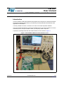
1
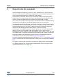
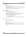
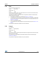
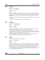
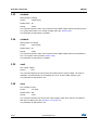
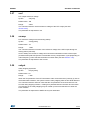
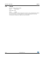
UM1881 User manual EVLSTNRG-170W: user interface manual Introduction The EVLSTNRG-170W demonstration board implements a simple user interface that allows the operator modifying temporarily or permanently several parameters that determine the application functionalities. It is also possible to monitor, in real time, the value of the most important variables. This user manual describes the commands available and how to use the interface. From the hardware point of view just a USB to UART (3.5 mm jack) cable is required. A picture of a working board with the serial interface in use is shown in Figure 1. Figure 1. EVLSTNRG-170W with serial interface in use June 2015 DocID027686 Rev 1 1/32 www.st.com 32 Contents UM1881 Contents 1 Getting started . . . . . . . . . . . . . . . . . . . . . . . . . . . . . . . . . . . . . . . . . . . . . . 5 1.1 System requirements . . . . . . . . . . . . . . . . . . . . . . . . . . . . . . . . . . . . . . . . . 5 1.2 General input rules . . . . . . . . . . . . . . . . . . . . . . . . . . . . . . . . . . . . . . . . . . . 5 1.3 Online help . . . . . . . . . . . . . . . . . . . . . . . . . . . . . . . . . . . . . . . . . . . . . . . . . 6 2 General rules for commands . . . . . . . . . . . . . . . . . . . . . . . . . . . . . . . . . . 7 3 Available commands . . . . . . . . . . . . . . . . . . . . . . . . . . . . . . . . . . . . . . . . . 8 2/32 3.1 acpdelay . . . . . . . . . . . . . . . . . . . . . . . . . . . . . . . . . . . . . . . . . . . . . . . . . . . 8 3.2 acpdelta . . . . . . . . . . . . . . . . . . . . . . . . . . . . . . . . . . . . . . . . . . . . . . . . . . . 8 3.3 acpexit . . . . . . . . . . . . . . . . . . . . . . . . . . . . . . . . . . . . . . . . . . . . . . . . . . . . 9 3.4 adt . . . . . . . . . . . . . . . . . . . . . . . . . . . . . . . . . . . . . . . . . . . . . . . . . . . . . . . 9 3.5 display . . . . . . . . . . . . . . . . . . . . . . . . . . . . . . . . . . . . . . . . . . . . . . . . . . . . 9 3.6 dllc . . . . . . . . . . . . . . . . . . . . . . . . . . . . . . . . . . . . . . . . . . . . . . . . . . . . . . 10 3.7 dlramp . . . . . . . . . . . . . . . . . . . . . . . . . . . . . . . . . . . . . . . . . . . . . . . . . . . 10 3.8 dpfc . . . . . . . . . . . . . . . . . . . . . . . . . . . . . . . . . . . . . . . . . . . . . . . . . . . . . . .11 3.9 dserv . . . . . . . . . . . . . . . . . . . . . . . . . . . . . . . . . . . . . . . . . . . . . . . . . . . . .11 3.10 dvin . . . . . . . . . . . . . . . . . . . . . . . . . . . . . . . . . . . . . . . . . . . . . . . . . . . . . . 12 3.11 dvout . . . . . . . . . . . . . . . . . . . . . . . . . . . . . . . . . . . . . . . . . . . . . . . . . . . . 12 3.12 factory . . . . . . . . . . . . . . . . . . . . . . . . . . . . . . . . . . . . . . . . . . . . . . . . . . . 12 3.13 help . . . . . . . . . . . . . . . . . . . . . . . . . . . . . . . . . . . . . . . . . . . . . . . . . . . . . 13 3.14 hwconf . . . . . . . . . . . . . . . . . . . . . . . . . . . . . . . . . . . . . . . . . . . . . . . . . . . 13 3.15 kil . . . . . . . . . . . . . . . . . . . . . . . . . . . . . . . . . . . . . . . . . . . . . . . . . . . . . . . 13 3.16 kih . . . . . . . . . . . . . . . . . . . . . . . . . . . . . . . . . . . . . . . . . . . . . . . . . . . . . . . 14 3.17 kpl . . . . . . . . . . . . . . . . . . . . . . . . . . . . . . . . . . . . . . . . . . . . . . . . . . . . . . . 14 3.18 kph . . . . . . . . . . . . . . . . . . . . . . . . . . . . . . . . . . . . . . . . . . . . . . . . . . . . . . 14 3.19 llcac . . . . . . . . . . . . . . . . . . . . . . . . . . . . . . . . . . . . . . . . . . . . . . . . . . . . . 15 3.20 llcdead . . . . . . . . . . . . . . . . . . . . . . . . . . . . . . . . . . . . . . . . . . . . . . . . . . . 15 3.21 llcs . . . . . . . . . . . . . . . . . . . . . . . . . . . . . . . . . . . . . . . . . . . . . . . . . . . . . . 16 3.22 llcstart . . . . . . . . . . . . . . . . . . . . . . . . . . . . . . . . . . . . . . . . . . . . . . . . . . . . 16 3.23 llcstop . . . . . . . . . . . . . . . . . . . . . . . . . . . . . . . . . . . . . . . . . . . . . . . . . . . . 16 DocID027686 Rev 1 UM1881 Contents 3.24 mincurr . . . . . . . . . . . . . . . . . . . . . . . . . . . . . . . . . . . . . . . . . . . . . . . . . . . 17 3.25 nompwr . . . . . . . . . . . . . . . . . . . . . . . . . . . . . . . . . . . . . . . . . . . . . . . . . . . 17 3.26 nshift . . . . . . . . . . . . . . . . . . . . . . . . . . . . . . . . . . . . . . . . . . . . . . . . . . . . . 17 3.27 ocpdelay . . . . . . . . . . . . . . . . . . . . . . . . . . . . . . . . . . . . . . . . . . . . . . . . . . 18 3.28 ocppwr . . . . . . . . . . . . . . . . . . . . . . . . . . . . . . . . . . . . . . . . . . . . . . . . . . . 18 3.29 ocpdelta . . . . . . . . . . . . . . . . . . . . . . . . . . . . . . . . . . . . . . . . . . . . . . . . . . 18 3.30 ocptime . . . . . . . . . . . . . . . . . . . . . . . . . . . . . . . . . . . . . . . . . . . . . . . . . . . 19 3.31 ovp . . . . . . . . . . . . . . . . . . . . . . . . . . . . . . . . . . . . . . . . . . . . . . . . . . . . . . 19 3.32 pfcdelay . . . . . . . . . . . . . . . . . . . . . . . . . . . . . . . . . . . . . . . . . . . . . . . . . . 19 3.33 pfcocp . . . . . . . . . . . . . . . . . . . . . . . . . . . . . . . . . . . . . . . . . . . . . . . . . . . . 20 3.34 pfcs . . . . . . . . . . . . . . . . . . . . . . . . . . . . . . . . . . . . . . . . . . . . . . . . . . . . . . 20 3.35 ratio . . . . . . . . . . . . . . . . . . . . . . . . . . . . . . . . . . . . . . . . . . . . . . . . . . . . . 20 3.36 reset . . . . . . . . . . . . . . . . . . . . . . . . . . . . . . . . . . . . . . . . . . . . . . . . . . . . . 21 3.37 rudelta . . . . . . . . . . . . . . . . . . . . . . . . . . . . . . . . . . . . . . . . . . . . . . . . . . . 21 3.38 rutfast . . . . . . . . . . . . . . . . . . . . . . . . . . . . . . . . . . . . . . . . . . . . . . . . . . . . 21 3.39 rutmax . . . . . . . . . . . . . . . . . . . . . . . . . . . . . . . . . . . . . . . . . . . . . . . . . . . 21 3.40 rutslow . . . . . . . . . . . . . . . . . . . . . . . . . . . . . . . . . . . . . . . . . . . . . . . . . . . 22 3.41 seteedata . . . . . . . . . . . . . . . . . . . . . . . . . . . . . . . . . . . . . . . . . . . . . . . . . 22 3.42 synch . . . . . . . . . . . . . . . . . . . . . . . . . . . . . . . . . . . . . . . . . . . . . . . . . . . . 22 3.43 tdelmax . . . . . . . . . . . . . . . . . . . . . . . . . . . . . . . . . . . . . . . . . . . . . . . . . . . 23 3.44 tdelmin . . . . . . . . . . . . . . . . . . . . . . . . . . . . . . . . . . . . . . . . . . . . . . . . . . . 23 3.45 tonblank . . . . . . . . . . . . . . . . . . . . . . . . . . . . . . . . . . . . . . . . . . . . . . . . . . 23 3.46 trace . . . . . . . . . . . . . . . . . . . . . . . . . . . . . . . . . . . . . . . . . . . . . . . . . . . . . 24 3.47 trrate . . . . . . . . . . . . . . . . . . . . . . . . . . . . . . . . . . . . . . . . . . . . . . . . . . . . . 24 3.48 uvp . . . . . . . . . . . . . . . . . . . . . . . . . . . . . . . . . . . . . . . . . . . . . . . . . . . . . . 25 3.49 vctrl . . . . . . . . . . . . . . . . . . . . . . . . . . . . . . . . . . . . . . . . . . . . . . . . . . . . . . 25 3.50 vctrloff . . . . . . . . . . . . . . . . . . . . . . . . . . . . . . . . . . . . . . . . . . . . . . . . . . . . 25 3.51 vers . . . . . . . . . . . . . . . . . . . . . . . . . . . . . . . . . . . . . . . . . . . . . . . . . . . . . 25 3.52 vin . . . . . . . . . . . . . . . . . . . . . . . . . . . . . . . . . . . . . . . . . . . . . . . . . . . . . . . 25 3.53 vinstart . . . . . . . . . . . . . . . . . . . . . . . . . . . . . . . . . . . . . . . . . . . . . . . . . . . 26 3.54 vinbout . . . . . . . . . . . . . . . . . . . . . . . . . . . . . . . . . . . . . . . . . . . . . . . . . . . 26 3.55 vout . . . . . . . . . . . . . . . . . . . . . . . . . . . . . . . . . . . . . . . . . . . . . . . . . . . . . 26 3.56 vrec . . . . . . . . . . . . . . . . . . . . . . . . . . . . . . . . . . . . . . . . . . . . . . . . . . . . . 26 DocID027686 Rev 1 3/32 32 Contents 4 4/32 UM1881 3.57 vref . . . . . . . . . . . . . . . . . . . . . . . . . . . . . . . . . . . . . . . . . . . . . . . . . . . . . . 27 3.58 vrramp . . . . . . . . . . . . . . . . . . . . . . . . . . . . . . . . . . . . . . . . . . . . . . . . . . . 27 3.59 vshyst . . . . . . . . . . . . . . . . . . . . . . . . . . . . . . . . . . . . . . . . . . . . . . . . . . . . 27 3.60 vstep . . . . . . . . . . . . . . . . . . . . . . . . . . . . . . . . . . . . . . . . . . . . . . . . . . . . . 28 3.61 zcddac . . . . . . . . . . . . . . . . . . . . . . . . . . . . . . . . . . . . . . . . . . . . . . . . . . . 28 3.62 zcdel . . . . . . . . . . . . . . . . . . . . . . . . . . . . . . . . . . . . . . . . . . . . . . . . . . . . . 28 3.63 zcdsbeg . . . . . . . . . . . . . . . . . . . . . . . . . . . . . . . . . . . . . . . . . . . . . . . . . . 28 3.64 zcdsend . . . . . . . . . . . . . . . . . . . . . . . . . . . . . . . . . . . . . . . . . . . . . . . . . . 29 3.65 zcdthrhi . . . . . . . . . . . . . . . . . . . . . . . . . . . . . . . . . . . . . . . . . . . . . . . . . . . 29 3.66 zcdthrlo . . . . . . . . . . . . . . . . . . . . . . . . . . . . . . . . . . . . . . . . . . . . . . . . . . . 29 3.67 zcdwait . . . . . . . . . . . . . . . . . . . . . . . . . . . . . . . . . . . . . . . . . . . . . . . . . . . 30 Revision history . . . . . . . . . . . . . . . . . . . . . . . . . . . . . . . . . . . . . . . . . . . 31 DocID027686 Rev 1 UM1881 Getting started 1 Getting started 1.1 System requirements In order to use the EVLSTNRG-170W user interface the following HW/SW tools are required: USB to UART cable (with 3.5 mm stereo jack) - example: FTDI Chip p/n TTL-232R-3V3-AJ PC driver for the USB to UART cable (provided by cable manufacturer) Terminal emulator client on the PC (like HyperTerminal or Tera Term) The serial interface has the following fixed configuration: 115200 bps 8 bit data No parity No flow control No echo After the power-on or hardware reset the application displays a version message followed by the input prompt. The initial prompt may vary on different revisions of the code; Figure 2 displays the initial prompt of the revision available at the time of writing this document. Figure 2. Initial prompt 1.2 General input rules The following general rules apply to all command input sequence: All commands are typed in lowercase letters The backspace character (ASCII code 0x08) may be used to cancel typed characters The Ctrl C character (ASCII code 0x03) may be used to cancel typed input and to restart a new input prompt All numbers unless explicitly indicated, are entered in the decimal format The arrow keys have no edit capability Input lines are terminated by a carriage return (ASCII code 0x0D) DocID027686 Rev 1 5/32 32 Getting started 1.3 UM1881 Online help The application has a simple online help feature that may be used to remind the syntax of the available commands. The help command has the two following formats: help help command_name The first version displays the list of all the available commands with their syntax in a short form. The second version displays a more complete syntax of the specified command in a long format; an example is displayed in Figure 3 for the help command itself. Figure 3. Help command example 6/32 DocID027686 Rev 1 UM1881 2 General rules for commands General rules for commands Several available commands may have one or more parameters; as a general rule if the command is entered without parameter(s), it displays the current setting of the parameter, while if entered with parameter(s), modifies the current settings. All parameters have default values that are automatically initialized at the absolute first system power-on and are stored permanently in the EEPROM data. Permanently means that their values are maintained across hardware resets and power-on resets. At the power-on or hardware reset, the values of all parameters stored in EEPROM data are automatically copied into their corresponding RAM locations for run-time usage. The EEPROM data are protected by a checksum to avoid data corruption. Before copying parameters from the EEPROM to RAM, the checksum is verified. Only if the checksum is correct the parameters are copied into the RAM, otherwise the EEPROM contents are replaced with the default parameter values and then copied into the RAM. Whenever the user modifies a parameter using the appropriate command, the parameter value is changed only in the RAM location for immediate run-time usage, while the EEPROM copy remains unaltered. At the next hardware reset or power-on reset, the value in the RAM location is restored from the EEPROM data loosing the temporary modification. Parameters stored in the EEPROM may also be restored in the RAM after temporary modifications using the reset command (see Section 3.36 on page 21). To modify permanently a parameter the user must use the seteedata (see Section 3.41 on page 22) command that copies the RAM location values into the corresponding EEPROM data. The system is delivered with a default set of parameters already stored in the EEPROM. The default parameters may be restored into the EEPROM at any time using the factory command (see Section 3.12 on page 12). DocID027686 Rev 1 7/32 32 Available commands 3 UM1881 Available commands This section describes the format and the function of all the available commands. The commands are sorted in alphabetical order to simplify the search. The full list of available commands may be displayed with the help command without any parameter. 3.1 acpdelay Anti-capacitive protection delay Syntax: acpdelay [ms] Default value: 20 ms Range: 1-1000 The LLC may enter the capacitive conditions if the ZCD signal event is too near to the switch on event (on anyone of the high- or low-side MOS; see Section 3.19 on page 15). This parameter indicates the maximum time in ms during which this condition may be accepted. If the capacitive condition persists for a longer period, a restart condition is generated by the LLC. When the capacitive condition if firstly recognized an internal timer is started and incremented until the capacitive condition persists. The acpdelay parameter indicates the maximum acceptable period for capacitive condition. If the capacitive condition persists for a time longer than this value, the LLC generates a restart condition. During the capacitive condition the LLC control loop is opened and the TimeShift parameter decremented every 250 µs until the condition persists (resonant frequency increment; see Section 3.2). 3.2 acpdelta Anti-capacitive protection delta Syntax: acpdelta [value] Default value: 4 Range: 1-255 This parameter indicates the decrement amount of the TimeShift parameter during the capacitive condition (see Section 3.1). The parameter is expressed in SMED clock cycles at 96 MHz. 8/32 DocID027686 Rev 1 UM1881 3.3 Available commands acpexit Anti-capacitive protection exit Syntax: acpexit [value] Default value: 30 Range: 1-1000 To exit from the LLC capacitive condition the distance between the switch on event and the ZCD event must be greater than this parameter. The parameter must be greater than the limit used to enter the capacitive condition in order to have an hysteresis between the enter and exit condition (see Section 3.19 on page 15). The parameter is expressed in SMED clock cycles at 96 MHz. 3.4 adt Automatic dead time Syntax: adt [on|off] Default value: on The dead time between the switching of the high-side and low-side MOS may be automatically detected by the system hardware. This parameter enables/disables this feature. If the feature is disabled, the dead time is determined by the llc_dead parameter (see Section 3.20 on page 15). 3.5 display Display all settable parameters Syntax: display The command displays the current value of all settable parameters. The value displayed is the one currently stored in the run-time RAM copy. The command automatically recalls all the partial display commands available to display only specific parameters (see following dxxx commands). DocID027686 Rev 1 9/32 32 Available commands 3.6 UM1881 dllc Display LLC parameters Syntax: dllc The command displays all the parameters related to the LLC configuration; the displayed parameters are: LLC start LLC stop LLC dead LLC ac ACP delay ACP exit OCP delay OCP pwr NOM pwr Tdel max Tdel min See the corresponding commands for the meaning of each parameter. 3.7 dlramp Display LLC startup ramp parameters Syntax: dlramp The command displays all the parameters related to the LLC startup ramp; the displayed parameters are: Ramp-up maximum time Ramp-up time fast increment Ramp-up time increment period Ramp-up time slow increment OCP time increment OCP time increment period ACP time increment See the corresponding commands for the meaning of each parameter. 10/32 DocID027686 Rev 1 UM1881 3.8 Available commands dpfc Display PFC parameters Syntax: dpfc The command displays all the parameters related to the PFC configuration; the displayed parameters are: Ton blank (LEB time) ZCD delay ZCD dac ZCD wait Valley skipping hysteresis PFC restart delay ZCD suppression high threshold ZCD suppression low threshold ZCD suppression begin ZCD suppression end PFC overcurrent protection Minimum current Steady-state and transition state integral parameter Steady-state and transition state proportional parameter Normalization compensation output shift See the corresponding commands for the meaning of each parameter. 3.9 dserv Display global service parameters Syntax: dserv The command displays global parameters related to the system configuration; the displayed parameters are: Automatic dead time Hardware configuration Current LLC state Current PFC state Current half bridge feedback control voltage See the corresponding commands for the meaning of each parameter. DocID027686 Rev 1 11/32 32 Available commands 3.10 UM1881 dvin Display mains control parameters Syntax: dvin The command displays all the parameters related to the control of the mains voltage levels; the displayed parameters are: Current mains input voltage Minimum mains input voltage level for PFC startup Minimum mains input voltage level to maintain PFC active Synchronization count for ADC interrupt function Coefficient for computation of feed-forward compensation See the corresponding commands for the meaning of each parameter. 3.11 dvout Display PFC output voltage control parameters Syntax: dvout The command displays all the parameters related to the control of the PFC output voltage; the displayed parameters are: Current PFC output voltage PFC output reference voltage PFC reference voltage ramp step PFC overvoltage protection level PFC recovery voltage level after burst PFC undervoltage protection level See the corresponding commands for the meaning of each parameter. 3.12 factory Restore default factory parameter values into the EEPROM and RAM. Syntax: factory The command restores the default factory parameter values both into the EEPROM and RAM memory locations (see also Section 2 on page 7, Section 3.36 on page 21 and Section 3.41 on page 22). 12/32 DocID027686 Rev 1 UM1881 3.13 Available commands help Help command Syntax: help [cmd_name] The command, when called without parameters, displays the list of all available commands with their syntax in a short form. If a valid command name is passed as a parameter, the command displays the syntax of the selected command and a short description of the command function. 3.14 hwconf Hardware configuration settings Syntax: hwconf [pfcon|pfclock|pfcoff|llcon|llclock|llcoff] Default value: PFC active LLC active The PFC and LLC subsystem may be enabled independently for test purposes. The command displays the current activation state of the PFC and LLC sections. Both PFC and LLC may be in the following state: 3.15 Off: the subsystem is not activated On: the subsystem is active Locked: the subsystem is activated but the corresponding SMED(s) are not activated (test functionality). kil Integral coefficient value for steady-state Syntax: kil [value] Default value: 43 Range: 1-1023 Without any parameter, the command displays the value of the integral coefficient used when the system is in steady-state. If a parameter is entered, the value is assigned to the integral coefficient used for steadystate. DocID027686 Rev 1 13/32 32 Available commands 3.16 UM1881 kih Integral coefficient value for transition state Syntax: kih [value] Default value: 462 Range: 1-1023 Without any parameter, the command displays the value of the integral coefficient used when the system is in transition state. If a parameter is entered, the value is assigned to the integral coefficient used for transition state. 3.17 kpl Proportional coefficient value for steady-state Syntax: kpl [value] Default value: 230 Range: 1-1024 Without any parameter, the command displays the value of the proportional coefficient used when the system is in steady-state. If a parameter is entered, the value is assigned to the proportional coefficient for steadystate. 3.18 kph Proportional coefficient value for transition state Syntax: kph [value] Default value: 920 Range: 1-1024 Without any parameter, the command displays the value of the proportional coefficient used when the system is in transition state. If a parameter is entered, the value is assigned to the proportional coefficient for transition state. 14/32 DocID027686 Rev 1 UM1881 3.19 Available commands llcac LLC anti-capacitive detection limit Syntax: llcac [value] Default value: 24 Range: 1-960 The command sets the value of the delay between the LLC switch on event and the ZCD event to enter the capacitive condition. If the delay is less than the parameter value, the capacitive condition is entered and the following actions are executed: The capacitive condition timer is started (see Section 3.1 on page 8) The detection limit is decreased to the minimum while the exit condition is determined by the acpexit parameter (need hysteresis between llcac and acpexit parameters, see Section 3.3 on page 9) The LLC control loop is opened The TimeShift value is decremented at every ADC interrupt cycle (see Section 3.2 on page 8). The parameter is expressed in SMED clock cycles at 96 MHz. 3.20 llcdead LLC dead time Syntax: llcdead [value] Default value: 80 Range: 1-255 The command sets the maximum dead time between the high-side switch off and low-side switch on (and vice versa). This timeout may be interrupted if the automatic dead time function is activated (see Section 3.4 on page 9). The parameter is expressed in SMED clock cycles at 96 MHz. DocID027686 Rev 1 15/32 32 Available commands 3.21 UM1881 llcs LLC status display control Syntax: llcs [on|off] Default value: on The command enables/disables the automatic display of every change in the LLC state machine. If the command is enabled, at every change of the LLC state machine a monitoring message is displayed indicating the new state. The possible LLC states are the following: 3.22 RESET initial state IDLE idle state before restarting BURST burst mode (minimum load) INIT initialization, tank discharge, boot charge RAMPUP decrease frequency until stable output RUNNING nominal working mode SWITCHOFF increase frequency before to switch off LLC OCP Iavg overcurrent protection ACP anti-capacitive protection llcstart Syntax: llcstart [volt] Default value: 380 Range: 3-500 The command sets the minimum PFC output voltage required to start the LLC resonant half bridge. This level is verified to start the LLC after a power up sequence or after a restart of the system (see also Section 3.23). The parameter is expressed in volt. 3.23 llcstop Syntax: llcstop [volt] Default value: 300 Range: 3-500 The command sets the minimum PFC output voltage required to maintain active the LLC resonant half bridge. This level is verified to stop the LLC due to an insufficient supply from PFC (see also Section 3.22). The parameter is expressed in volt. 16/32 DocID027686 Rev 1 UM1881 3.24 Available commands mincurr Minimum PFC current level Syntax: mincurr [value] Default value: 40 Range: 1-255 The command sets the minimum level of the current in the boost inductor before starting the Ton period. This minimum current level is used both to compensate the negative current during the switch on phase and to compensate crossover conduction during the mains zero crossing. The parameter controls a PWM signal that generates the reference level for the PFC current comparator. The parameter is expressed in SMED clock cycles at 48 MHz. 3.25 nompwr Nominal power reference for LLC Syntax: nompwr [value] Default value: 26000 Range: 1-32000 The command sets the reference value for the LLC output power under which the system reenters the normal operations after an overcurrent protection event. The parameter is used as a base value to compute at run-time the reference current for the half bridge average current level; the computed value is dynamically updated depending on the value of the PFC output voltage (see also Section 3.28). The parameter at this moment does not have a unit measure; future versions of the firmware may support a reference unit (e.g.: output power in Watt). 3.26 nshift Normalization shift count for PFC compensation Syntax: nsfhift [value] Default value: 4 Range: 1-15 The compensation algorithm used to control the PFC system generates a control parameter that has a signed 16-bit value to maintain the maximum precision during the computation. This value must be normalized before to apply it to the SMED0 as the Ton parameter, and limited to a maximum value, that determines the maximum PFC switching on time. The parameter determines the number of right shifts applied to the algorithm result to obtain the Ton value (divisions by powers of 2). DocID027686 Rev 1 17/32 32 Available commands 3.27 UM1881 ocpdelay Maximum duration of overcurrent protection condition Syntax: ocpdelay [value] Default value: 100 Range: 10-1000 The command sets the maximum duration of the LLC overcurrent protection condition. When the LLC average current exceeds the overcurrent protection level (see Section 3.28), the system enters the OCP condition and executes the following actions: Set the LLC OCP condition Start the timeout control Open the LLC control loop Decrement the time shift (see parameters Section 3.29 and Section 3.30) The parameter is expressed in milliseconds. 3.28 ocppwr Overcurrent protection power reference for LLC Syntax: ocppwr [value] Default value: 28000 Range: 1-32000 The command sets the reference value for the LLC output power over which the system enters the overcurrent protection state starting the corresponding timeout (see Section 3.27). The parameter is used as a base value to compute at run-time the reference current for the half bridge average current level; the computed value is dynamically updated depending on the value of the PFC output voltage (see alsoSection 3.25). The parameter at this moment does not have a unit measure; future versions of the firmware may support a reference unit (e.g.: output power in Watt). 3.29 ocpdelta LLC time shift decrement during OCP Syntax: ocpdelta Default value: 1 Range: 1-255 The command sets the decrement value for the time shift parameter during the OCP condition (see also Section 3.30). The parameter is expressed in SMED clock cycles at 96 MHz. 18/32 DocID027686 Rev 1 UM1881 3.30 Available commands ocptime LLC time shift decrement period during OCP Syntax: ocptime Default value: 2 Range: 1-255 The command sets the decrement period value for the time shift parameter during the OCP condition (see also Section 3.29). The parameter is expressed in ADC interrupt cycles. 3.31 ovp PFC overvoltage protection Syntax: ovp [volt] Default value: 430 Range: 3-450 At every ADC interrupt cycle, the system checks that the PFC output voltage is under this reference value. If the limit is exceeded the PFC enters the burst mode switching off the MOS (see also Section 3.56 on page 26). The parameter is expressed in volt. 3.32 pfcdelay PFC restart time after reset Syntax: pfcdelay [value] Default value: 1000 Range: 10-15000 Depending on the mains input value and on the output load, the PFC+LLC system may be turned off to avoid critical conditions. In this case, the system tries to restart automatically. The command sets the timeout period before to retry an automatic restart of the system. The parameter is expressed in milliseconds. DocID027686 Rev 1 19/32 32 Available commands 3.33 UM1881 pfcocp PFC absolute current limit Syntax: pfcocp [value] Default value: 11 Range: 1-15 The command sets the maximum absolute current limit for the PFC boost inductor. If this limit is exceeded the MOS is immediately switched off. This control is always active at every switching cycle. The parameter is expressed in steps of the DAC used by the current sensing comparator; each step corresponds to about 83 mV on the current sensing resistor. 3.34 pfcs PFC status display control Syntax: pfcs [on|off] Default value: on The command enables/disables the automatic display of every change in the PFC state machine. If the command is enabled, at every change of the PFC state machine a monitoring message is displayed indicating the new state. The possible PFC states are the following: 3.35 RESET initial state VINSTART waiting for Vin > Vinstart RAMPUP moving Vref up to nominal RUNNING nominal working mode BURST PFC active pulse during burst conditions RESTART restart condition after an LLC HB_ocp2 ratio Feed-forward reference Syntax: ratio [value] Default value: 3300 Range: 100-65535 The command sets the reference value for the computation of the feed-forward compensation to be applied to the proportional and integral coefficients due to variations of the mains level. The value is strictly connected to internal computation rules used by the PFC compensation algorithm and has no measure unit. 20/32 DocID027686 Rev 1 UM1881 3.36 Available commands reset Restore parameter values. Syntax: reset The command restores the values of all the system parameters copying their values from the EEPROM data to their corresponding RAM locations (see also Section 2 on page 7 and Section 3.41). 3.37 rudelta LLC ramp-up fast mode increment value Syntax: rudelta [value] Default value: 4 Range: 1-255 The command sets the increment value of the time shift parameter during the LLC fast ramp-up phase (see also Section 3.38, Section 3.39, and Section 3.40). The parameter is expressed in SMED clock cycles at 96 MHz. 3.38 rutfast LLC ramp-up fast mode increment period Syntax: rutfast [value] Default value: 6 Range: 1-255 The command sets the increment period of the time shift parameter during the LLC fast ramp-up phase (see also Section 3.37, Section 3.39, and Section 3.40). The parameter is expressed in ADC interrupt cycles. 3.39 rutmax LLC ramp-up maximum time Syntax: rutmax [value] Default value: 400 Range: 1-1023 The command sets the maximum value of the time shift parameter during the LLC fast ramp-up phase. When this value is exceeded, the ramp-up automatically switches to the slow phase (see also Section 3.37, Section 3.38, and Section 3.40). The parameter is expressed in SMED clock cycles at 96 MHz. DocID027686 Rev 1 21/32 32 Available commands 3.40 UM1881 rutslow LLC ramp-up slow mode increment period Syntax: rutslow [value] Default value: 2 Range: 1-255 The command sets the increment period of the time shift parameter during the LLC slow ramp-up phase (see also Section 3.37, Section 3.38, and Section 3.39). The parameter is expressed in ADC interrupt cycles. 3.41 seteedata Write parameters in EEPROM data Syntax: seteedata The command updates the contents of the EEPROM data copying all the parameters from their RAM locations to the corresponding EEPROM data. The values stored by this command are maintained through hardware resets and power-on resets (see also Section 2 on page 7 and Section 3.36). 3.42 synch Synchronization count for PFC Syntax: synch [value] Default value: 128 Range: 0-255 The command sets the synchronization point for the ADC interrupt routine. The value indicates the distance (in ADC interrupt cycles) between the mains peak value detected by the synchronization SMED and the real mains zero cross. This is necessary because the detected zero crossing may be misaligned due to distortion of the measured rectified mains voltage. The parameter is expressed in ADC interrupt cycles. 22/32 DocID027686 Rev 1 UM1881 3.43 Available commands tdelmax LLC absolute maximum time shift Syntax: tdelmax [value] Default value: 960 Range: 1-1023 The command sets the absolute maximum value that may be assigned to the time shift parameter of the LLC (see also Section 3.44). This determines the minimum working frequency of the LLC half bridge. The parameter is expressed in SMED clock cycles at 96 MHz. 3.44 tdelmin LLC absolute minimum time shift Syntax: tdelmin [value] Default value: 48 Range: 1-1023 The command sets the absolute minimum value that may be assigned to the time shift parameter of the LLC (see also Section 3.43). This determines the maximum working frequency of the LLC half bridge. The parameter is expressed in SMED clock cycles at 96 MHz. 3.45 tonblank PFC blanking time (LEB) Syntax: tonblank [value] Default value: 25 Range: 1-10000 The command sets the duration of the LEB time (“Leading Edge Blanking”) after the switch on of the PFC MOS. During this period, the current sensing comparator is disabled. The parameter is expressed in SMED clock cycles at 96 MHz. DocID027686 Rev 1 23/32 32 Available commands 3.46 UM1881 trace Tracing monitor function Syntax: trace [name1 [name2 […]]] The command is used to configure the monitoring capability of the PFC LLC system. The command selects which parameters to display at every tracing cycle (see Section 3.47); each parameter is identified by a two-letter name. The command may be repeated with difference parameters adding new elements to the current display list. The list of selectable parameters and their meaning is the following: 3.47 en enable tracing di disable tracing and maintains selected parameters list cl disable tracing and clear selected parameters list vo PFC output voltage vi mains RMS voltage co PFC compensation output (Ton value) pr proportional compensation in integral compensation ia integral accumulator or PFC output raw voltage vc LLC feedback raw voltage (time shift) ve PFC compensation error vs number of valley skipping inserted ac LLC average current trrate Tracing rate Syntax: trrate [value] Default value: 50 Range: 1-255 The command sets the rate of the tracing function, which is the display frequency of the parameters selected (see Section 3.46). The parameter is expressed in multiples of the 10 ms cycles. 24/32 DocID027686 Rev 1 UM1881 3.48 Available commands uvp PFC undervoltage protection Syntax: uvp [volt] Default value: 300 Range: 2-380 The command sets the minimum level of the PFC output voltage under which the entire system is turned off to avoid critical conditions (typically temporary overload). The system is automatically restarted after a configurable delay (see Section 3.32 on page 19). The parameter is expressed in volt. 3.49 vctrl LLC feedback control voltage Syntax: vctrl The command displays the actual value of the feedback control voltage of the LLC half bridge. The parameter is expressed in ADC counts. 3.50 vctrloff LLC feedback optocoupler offset voltage Syntax: vctrloff The command sets the actual value of the offset subtracted from the feedback voltage of the LLC read from the optocoupler. The parameter is expressed in ADC counts. 3.51 vers System firmware version identification Syntax: vers The command displays the version of the system firmware. 3.52 vin Mains input voltage Syntax: vin The command displays the value of the last measured mains peak voltage. The value is updated every half cycle of the mains. The parameter is expressed in volt RMS. DocID027686 Rev 1 25/32 32 Available commands 3.53 UM1881 vinstart Mains brown-in voltage Syntax: vinstart [volt] Default value: 90 Range: 3-265 The command sets the value of the minimum mains RMS voltage required to start the PFC LLC system after power-on or restart condition (see also Section 3.54). The parameter is expressed in volt RMS. 3.54 vinbout Mains brown-out voltage Syntax: vinbout [volt] Default value: 80 Range: 3-265 The command sets the value of the minimum mains RMS voltage required to maintain the PFC LLC system active (see also Section 3.53). The parameter is expressed in volt RMS. 3.55 vout PFC output voltage Syntax: vout The command displays the value of the last measured PFC output voltage. The value is updated in a mobile window of 16 samples one out of 16 of the ADC interrupt cycle. The parameter is expressed in volt. 3.56 vrec PFC voltage recovery Syntax: vrec [volt] Default value: 390 Range: 2-390 The command sets the level of the PFC output voltage under which the PFC is restarted after burst condition (see also Section 3.31 on page 19). The parameter is expressed in volt. 26/32 DocID027686 Rev 1 UM1881 3.57 Available commands vref PFC output reference voltage Syntax: vref [volt] Default value: 400 Range: 3-500 The command sets the nominal reference voltage of the PFC output (see also Section 3.58). The parameter is expressed in volt. 3.58 vrramp PFC reference voltage increment during startup Syntax: vramp [value] Default value: 35 Range: 1-255 The command sets the increment of the reference voltage of the PFC output during the startup phase (soft start). At PFC startup, the reference voltage is forced at the instantaneous value of the output (rectified mains peak value) and is incremented at every compensation cycle (depending on mains frequency) until it reaches the defined nominal value (see also Section 3.57). The parameter is expressed in ADC counts. 3.59 vshyst Valley skipping hysteresis Syntax: vshyst [value] Default value: 50 Range: 1-255 When the Ton parameter of the PFC decreases under a minimum level (currently 2), due to decreased load conditions, the system inserts a valley skipping after the first ZCD detected. The command sets the minimum value that the Ton parameter must reach before to exit from the valley skipping insertion, creating an hysteresis between the enter and exit value. The insertion of the valley skipping may be nested up to three levels before to enter the burst condition. The parameter is expressed in SMED clock cycles at 96 MHz. DocID027686 Rev 1 27/32 32 Available commands 3.60 UM1881 vstep Vin steps check enable flag Syntax: vstep [on/off] Default value: off The command enables/disables the checks performed inside the ADC ISR to verify the instantaneous changes of the Vin signal. 3.61 zcddac Level of the comparator for PFC ZCD Syntax: zcddac [value] Default value: 0 Range: 1-15 The command sets the level of the DAC used as reference value for the PFC ZCD. The parameter is expressed in steps of the DAC used by the zero cross detection comparator; each step corresponds to about 83 mV on the input voltage. 3.62 zcdel PFC zero crossing delay Syntax: zcdel [value] Default value: 5 Range: 1-1000 The command sets the delay inserted after the PFC has detected the zero crossing event, before to switch on the MOS for the next cycle. The parameter is expressed in SMED clock cycles at 96 MHz. 3.63 zcdsbeg PFC zero crossing detection suppression begin Syntax: zcdsbeg [value] Default value: 64 Range: 1-255 The command sets the value of the mains phase after which the zero crossing detection may be suppressed if necessary (see Section 3.64 and Section 3.65). The mains phase is determined by the number of ADC interrupts inside a single mains cycle; this value is fixed to 256 by the system synchronization independently from the mains frequency. Each ADC interrupt corresponds to 180/256 degrees. The parameter is expressed in ADC counts. 28/32 DocID027686 Rev 1 UM1881 3.64 Available commands zcdsend PFC zero crossing detection suppression end Syntax: zcdsend [value] Default value: 160 Range: 1-255 The command sets the value of the mains phase after which the zero crossing detection must be restored after eventual suppression (see Section 3.63 and Section 3.65). The mains phase is determined by the number of ADC interrupts inside a single mains cycle; this value is fixed to 256 by the system synchronization independently from the mains frequency. Each ADC interrupt corresponds to 180/256 degrees. The parameter is expressed in ADC counts. 3.65 zcdthrhi PFC zero crossing detection suppression level high threshold Syntax: zcdthrhi [value] Default value: 140 Range: 1-1000 The command sets the minimum value of the difference between the instantaneous levels of PFC output voltage and mains input voltage to enable the ZCD suppression to avoid continuous conduction mode in the PFC boost inductor. The suppression is enabled only if the actual mains phase is inside a configured range (see Section 3.63 and Section 3.64). The parameter is expressed in ADC counts. 3.66 zcdthrlo PFC zero crossing detection suppression level low threshold Syntax: zcdthrlo [value] Default value: 60 Range: 1-1000 The command sets the minimum value of the difference between the instantaneous levels of PFC output voltage and mains input voltage to double the off time to avoid continuous conduction mode in the PFC boost inductor. The suppression is enabled only if the PFC is already in the ZCD suppression mode (see Section 3.65). The parameter is expressed in ADC counts. DocID027686 Rev 1 29/32 32 Available commands 3.67 UM1881 zcdwait PFC zero crossing detection timeout Syntax: zcdwait [value] Default value: 7200 Range: 1-65535 The command sets the maximum waiting time for the PFC zero crossing detection event. If this time is exceeded, a new PFC MOS cycle is started independently from the ZDC. The parameter is expressed in SMED clock cycles at 96 MHz. 30/32 DocID027686 Rev 1 UM1881 4 Revision history Revision history Table 1. Document revision history Date Revision 23-Jun-2015 1 Changes Initial release. DocID027686 Rev 1 31/32 32 UM1881 IMPORTANT NOTICE – PLEASE READ CAREFULLY STMicroelectronics NV and its subsidiaries (“ST”) reserve the right to make changes, corrections, enhancements, modifications, and improvements to ST products and/or to this document at any time without notice. Purchasers should obtain the latest relevant information on ST products before placing orders. ST products are sold pursuant to ST’s terms and conditions of sale in place at the time of order acknowledgement. Purchasers are solely responsible for the choice, selection, and use of ST products and ST assumes no liability for application assistance or the design of Purchasers’ products. No license, express or implied, to any intellectual property right is granted by ST herein. Resale of ST products with provisions different from the information set forth herein shall void any warranty granted by ST for such product. ST and the ST logo are trademarks of ST. All other product or service names are the property of their respective owners. Information in this document supersedes and replaces information previously supplied in any prior versions of this document. © 2015 STMicroelectronics – All rights reserved 32/32 DocID027686 Rev 1