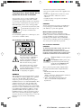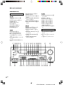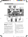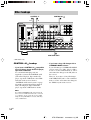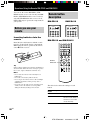
1
4-244-963-12(1)
FM Stereo
FM-AM Receiver
Operating Instructions
Owner’s Record
The model and serial numbers are located at the rear of the unit. Record the serial
number in the space provided below. Refer to them whenever you call upon your Sony
dealer regarding this product.
Model No.
Serial No.
STR-DE995
STR-DE895
© 2003 Sony Corporation
STR-DE995/895
4-244-963-12(1) GB
WARNING
To prevent fire or shock hazard, do not
expose the unit to rain or moisture.
To prevent fire, do not cover the ventilation of the
apparatus with newspapers, table-cloths, curtains,
etc. And don’t place lighted candles on the apparatus.
To prevent fire or shock hazard, do not place objects
filled with liquids, such as vases, on the apparatus.
Don’t throw away the battery with
general house waste, dispose of it
correctly as chemical waste.
– Reorient or relocate the receiving antenna.
– Increase the separation between the equipment and
receiver.
– Connect the equipment into an outlet on a circuit
different from that to which the receiver is
connected.
– Consult the dealer or an experienced radio/TV
technician for help.
CAUTION
You are cautioned that any changes or modification
not expressly approved in this manual could void
your authority to operate this equipment.
Note to CATV system installer:
Do not install the appliance in a confined space, such
as a bookcase or built-in cabinet.
For customers in the United States
This reminder is provided to call CATV system
installer’s attention to Article 820-40 of the NEC that
provides guidelines for proper grounding and, in
particular, specifies that the cable ground shall be
connected to the grounding system of the building, as
close to the point of cable entry as practical.
For customers in Canada
CAUTION
TO PREVENT ELECTRIC SHOCK, DO NOT USE
THIS POLARIZED AC PLUG WITH AN
EXTENSION CORD, RECEPTACLE OR OTHER
OUTLET UNLESS THE BLADES CAN BE FULLY
INSERTED TO PREVENT BLADE EXPOSURE.
This symbol is intended to alert the
user to the presence of uninsulated
“dangerous voltage” within the
product’s enclosure that may be of
sufficient magnitude to constitute a
risk of electric shock to persons.
This symbol is intended to alert the
user to the presence of important
operating and maintenance (servicing)
instructions in the literature
accompanying the appliance.
WARNING
2GB
This equipment has been tested and found to comply
with the limits for a Class B digital device, pursuant
to Part 15 of the FCC Rules. These limits are
designed to provide reasonable protection against
harmful interference in a residential installation. This
equipment generates, uses, and can radiate radio
frequency energy and, if not installed and used in
accordance with the instructions, may cause harmful
interference to radio communications. However, there
is no guarantee that interference will not occur in a
particular installation. If this equipment does cause
harmful interference to radio or television reception,
which can be determined by turning the equipment
off and on, the user is encouraged to try to correct the
interference by one or more of the following
measures:
ENERGY STAR® is a U.S. registered
mark.
As an ENERGY STAR® partner, Sony
Corporation has determined that this
product meets the ENERGY STAR®
guidelines for energy efficiency.
This receiver incorporates Dolby* Digital and Pro
Logic Surround and the DTS** Digital Surround
System.
* Manufactured under license from Dolby
Laboratories.
“Dolby”, “Pro Logic” and the double-D symbol are
trademarks of Dolby Laboratories.
** “DTS”, “DTS-ES Extended Surround” and
“Neo:6” are trademarks of Digital Theater
Systems, Inc.
Table of Contents
Recording ............................................ 40
Using the Sleep Timer ......................... 41
Adjustments using the CUSTOMIZE
menu .............................................. 42
Changing the command mode of the
receiver .......................................... 43
CONTROL A1II control system ......... 44
List of Button Locations and
Reference Pages
Main unit ............................................... 5
Hooking Up the Components
Required cords ....................................... 7
Antenna hookups ................................... 8
Audio component hookups .................... 9
Video component hookups .................. 10
Digital component hookups ................. 11
Multi channel input hookups ............... 13
Other hookups ..................................... 14
Operations Using the Remote
RM-PP4121) and RM-PG4122)
Before you use your remote ................ 46
Remote button description ................... 46
Selecting the command mode of the
remote ............................................ 50
Programming the remote ..................... 51
Learning the commands of your
components3) ................................. 54
Performing several commands in sequence
automatically (Macro Play)3) ........... 55
Hooking Up and Setting Up
the Speaker System
Speaker system hookups ..................... 17
Performing initial setup operations ..... 19
Multi channel surround setup .............. 19
Checking the connections .................... 24
Basic Operations
Operations Using the Remote
RM-LG1124)
Before you use your remote ................ 57
Remote button description ................... 57
Selecting the command mode of the
remote ............................................ 61
Programming the remote ..................... 61
Learning the commands of your
components ................................... 64
Performing several commands in sequence
automatically (Macro Play) ............. 66
Selecting the component ..................... 25
Listening to the sound in another room ... 27
Changing the display ........................... 27
Enjoying Surround Sound
Using only the front speakers
(2 Channel Stereo) ........................ 28
Enjoying higher fidelity sound ............ 28
Selecting a sound field ........................ 29
Selecting the surround back decoding mode
(SURR BACK DECODING) .......... 31
Understanding the multi channel
surround displays .......................... 33
Customizing sound fields .................... 34
Additional Information
Precautions .......................................... 67
Troubleshooting ................................... 67
Specifications ...................................... 70
Tables of settings using the MAIN
MENU button ................................ 73
Adjustable parameters for each sound
field ............................................... 75
Receiving Broadcasts
Direct tuning ........................................ 37
Automatic tuning ................................. 38
Preset tuning ........................................ 38
1)
STR-DE895 models of area code CA only.
STR-DE995 models of area code CA only and
STR-DE895 models of area code U, E2/E3, MX
only.
3)
RM-PG412 only.
4)
STR-DE995 models of area code U only.
2)
Other Operations
Naming preset stations and program
sources ........................................... 40
3GB
About This Manual
Note for the supplied remote
The instructions in this manual are for models
STR-DE995 and STR-DE895. Check your model
number by looking at the lower right corner of the
front panel. In this manual, the STR-DE995 is used
for illustration purposes unless stated otherwise. Any
difference in operation is clearly indicated in the text,
for example, “STR-DE995 only”.
About area codes
The area code of the receiver you purchased is
shown on the lower portion of the rear panel (see
the illustration below).
L
L
–
IMPEDANCE USE 8-16Ω
+
FRONT A
–
R
L
–
SURROUND
IMPEDANCE USE 8-16Ω
– (STR-DE995 only) The AAC BI-LING and
12 button on the remote are not available.
+
L
AC OUTLET
4-XXX-XXX-XX AA
Area code
Any differences in operation, according to the
area code, are clearly indicated in the text, for
example, “Models of area code AA only”.
Tip
The instructions in this manual describe the controls
on the receiver. You can also use the controls on the
supplied remote if they have the same or similar
names as those on the receiver. For details on the use
of your remote, see
• pages 46–53 for RM–PP412 (STR-DE895 models
of area code CA only).
• pages 46–56 for RM–PG412 (STR-DE995 models
of area code CA only and STR-DE895 models of
area code U, E2/E3, MX only).
• pages 57–66 for RM–LG112 (STR-DE995 models
of area code U only).
4GB
For RM-PG412 (STR-DE995 models of
area code CA only and STR-DE895
models of area code U, E2/E3, MX
only)
– (STR-DE895 only) The AAC BI-LING, 12
and ON SCREEN button on the remote are
not available.
R
FRONT B
SPEAKERS
S
The AUX, AAC BI-LING, 12 and ON
SCREEN button on the remote are not
available.
+
R
R
For RM-PP412 (STR-DE895 models of
area code CA only)
For RM-LG112 (STR-DE995 models of
area code U only)
The AAC BI-LING and 12 button on the
remote are not available.
List of Button Locations and Reference Pages
Illustration number
r
Use this page to find the location of buttons that are
mentioned in the text.
4 (27, 69)
DISPLAY
R
R
Name of button/part
Reference page
Main unit
STR-DE995 only
MD/TAPE (indicator) qs (25)
MEMORY eh (38)
MENU wh (20, 35, 36, 40, 42, 73)
MOVIE (button/indicator) e; (29,
30, 68)
MULTI CHANNEL DECODING
(indicator) wj (26)
MULTI CH IN/DIRECT wk (26)
MUSIC (button/indicator) wl (29,
30, 68)
ALPHABETICAL ORDER
A–H
A.F.D. (button/indicator) ea
(28–31)
CD/SACD (indicator) qd (25)
DIMMER 5 (27)
DISPLAY 4 (27, 69)
Display qf (27)
DVD (indicator) q; (25)
ENTER wf (19, 40, 43)
FM MODE ej (37)
O–S
ON SCREEN wa (10)
PHONES (jack) 3 (26, 33, 68)
PHONO (indicator) qh (25)
PRESET TUNING +/– ef (38,
39, 71)
SPEAKERS (OFF/A/B/A+B) 2
(17, 26, 67)
SURR BACK DECODING ed
(31, 42)
SURR BACK DECODING
(indicator) qj (31)
I–N
INPUT MODE ws (25)
INPUT SELECTOR w; (25)
IR (receptor) 6 (46, 57, 69)
MAIN MENU wd (20, 35, 36, 40,
42, 73)
MASTER VOLUME qk (24, 26,
67)
1 2345 6
7 8 9 q; qa qs qdqfqg qh
T–Z
TUNER FM/AM (indicator) qg
(25, 38–40)
TUNING +/– eg (38)
TV/SAT (indicator) qa (25)
VIDEO 1 (indicator) 7 (25)
VIDEO 2 (indicator) 8 (25)
VIDEO 3 (indicator) 9 (25)
VIDEO 3 DIGITAL INPUT
(OPT) (jack) el (11)
VIDEO 3 INPUT (jacks) ek (10,
11)
List of Button Locations and Reference Pages
How to use page 5 and 6
NUMBERS AND SYMBOLS
2CH (button/indicator) es (28,
30, 36)
2ND ZONE ql (27)
?/1 (power) 1 (19, 24, 36, 43,
71)
+/– wg (20, 35, 36, 40, 42, 73)
qj
qk
?/1
g
el
ek
ejeh eg
ef ed es ea e; wl wkwj wh
wg wfwdwswa w;
ql
continued
5GB
Main unit (continued)
STR-DE895 only
MD/TAPE (indicator) qs (25)
MEMORY ef (38)
MOVIE (button/indicator) wk (29,
30, 68)
MULTI CHANNEL DECODING
(indicator) wg (26)
MULTI CH IN/DIRECT wh (26)
MUSIC (button/indicator) wj (29,
30, 68)
ALPHABETICAL ORDER
A–H
A.F.D. (button/indicator) wl
(28–31)
CD/SACD (indicator) qd (25)
DIMMER 5 (27)
DISPLAY 4 (27, 69)
Display qf (27)
DVD (indicator) q; (25)
ENTER ws (19, 40, 43)
FM MODE eg (37)
P–S
PHONES (jack) 3 (26, 33, 68)
PHONO (indicator) qh (25)
PRESET TUNING +/– es (38,
39, 71)
SPEAKERS (OFF/A/B/A+B) 2
(17, 26, 67)
SURR BACK DECODING ea
(31, 42)
SURR BACK DECODING
(indicator) qj (31)
I–O
INPUT MODE w; (25)
INPUT SELECTOR ql (25)
IR (receptor) 6 (46, 57, 69)
Jog dial wf (20, 35, 36, 40, 42,
73)
MAIN MENU wa (20, 35, 36, 40,
42, 73)
MASTER VOLUME qk (24, 26,
67)
1 2345 6
7 8 9 q; qa qs qdqfqg qh
T–Z
TUNER FM/AM (indicator) qg
(25, 38–40)
TUNING +/– ed (38)
TV/SAT (indicator) qa (25)
VIDEO 1 (indicator) 7 (25)
VIDEO 2 (indicator) 8 (25)
VIDEO 3 (indicator) 9 (25)
VIDEO 3 DIGITAL INPUT
(OPT) (jack) ej (11)
VIDEO 3 INPUT (jacks) eh (10,
11)
NUMBERS AND SYMBOLS
2CH (button/indicator) e; (28,
30, 36)
?/1 (power) 1 (19, 24, 36, 43,
71)
</> wd (20, 35, 36, 40, 42, 73)
qj
qk
?/1
g
ej
6GB
eh
egef ed
es ea e; wl wk wj whwgwf
wd ws wa w;
ql
Hooking Up the Components
Required cords
A Audio cord (not supplied)
F Coaxial digital cord (not supplied)
White (L)
Red (R)
B Audio/video cord (not supplied)
Yellow (video)
White (L/audio)
Red (R/audio)
C Video cord (not supplied)
Yellow
G Monaural audio cord (not supplied)
Black
Tip
Audio cord A can be torn into two monaural audio
cords G.
H Component video cord (not supplied)
Green
Blue
Red
D S-video cord (not supplied)
E Optical digital cord (not supplied)
Hooking Up the Components
The following optional connection cords A – I are required when you hook up the components
(pages 9 – 15).
I Monaural mini-plug cord (not supplied)
Black
Before you get started
• Turn off the power to all components before making any connections.
• Do not connect the AC power cord until all of the connections are completed.
• Be sure to make connections firmly to avoid hum and noise.
• When connecting an audio/video cord, be sure to match the color-coded pins to the appropriate jacks on
the components: yellow (video) to yellow; white (left, audio) to white; and red (right, audio) to red.
• When you connect optical digital cords, insert the cord plugs straight in until they click into place.
• Do not bend or tie the optical digital cord.
7GB
Antenna hookups
AM loop antenna
(supplied)
FM wire antenna
(supplied)
DIGITAL
(ASSIGNABLE)
OPTICAL
ANTENNA
TV/SAT
IN
MD/
TAPE
IN
CTRL S CTRL S
STATUS STATUS
OUT
IN
S-VIDEO
IN
S-VIDEO
IN
S-VIDEO
OUT
S-VIDEO
IN
AM
MD/
TAPE
OUT
VIDEO IN
FM
75Ω
COAXIAL
y
DVD
IN
COAXIAL
SUB
WOOFER
VIDEO OUT VIDEO IN
R
AUDIO IN
L
R
AUDIO IN
L
R
AUDIO OUT AUDIO IN
VIDEO 2
L
L
IN
IN
PHONO CD/SACD
OUT
R
IN
FRONT
MD/TAPE
R
R
R
SURROUND
SUB
WOOFER
FRONT
*
* The shape of the connector varies depending on the area code.
• To prevent noise pickup, keep the AM loop
antenna away from the receiver and other
components.
• Be sure to fully extend the FM wire antenna.
• After connecting the FM wire antenna, keep it
as horizontal as possible.
• Do not use the U SIGNAL GND terminal for
grounding the receiver.
8GB
AUDIO OUT
AUDIO IN
VIDEO 1
L
CENTER
MULTI CH IN 2
Notes on antenna hookups
VIDEO IN
L
CENTER
R
VIDEO OUT
L
PRE OUT TV/SAT DVD
SIGNAL GND
L
VIDEO IN
L
y
CD/
SACD
IN
SURROUND
SURR
BACK
MULTI CH IN 1
SUB
WOOFER
OUT
R
2ND ZONE
Audio component hookups
MD or Tape deck
LINE
LINE
L
Turntable
A
A
ç
A
ç
R
OUT
IN
DIGITAL
(ASSIGNABLE)
OPTICAL
ANTENNA
TV/SAT
IN
MD/
TAPE
IN
CTRL S CTRL S
STATUS STATUS
OUT
IN
S-VIDEO
IN
S-VIDEO
IN
S-VIDEO
OUT
S-VIDEO
IN
Hooking Up the Components
INPUT OUTPUT
AM
MD/
TAPE
OUT
VIDEO IN
FM
75Ω
COAXIAL
y
DVD
IN
COAXIAL
SUB
WOOFER
VIDEO OUT VIDEO IN
R
AUDIO IN
L
R
L
R
AUDIO OUT AUDIO IN
AUDIO IN
VIDEO 2
L
IN
R
IN
R
OUT
IN
MD/TAPE
FRONT
R
SURROUND
SUB
WOOFER
MULTI CH IN 2
VIDEO IN
L
AUDIO OUT
AUDIO IN
VIDEO 1
L
CENTER
PHONO CD/SACD
VIDEO OUT
L
PRE OUT TV/SAT DVD
SIGNAL GND
L
VIDEO IN
L
y
CD/
SACD
IN
L
CENTER
R
FRONT
R
SURROUND
SURR
BACK
MULTI CH IN 1
SUB
WOOFER
OUT
R
2ND ZONE
A
OUTPUT
LINE
L
R
CD or Super Audio
CD player
Note on audio component
hookups
If your turntable has a ground wire, connect it
to the U SIGNAL GND terminal.
9GB
Video component hookups
Satellite tuner
DVD player
OUTPUT
OUTPUT
AUDIO OUT
L
R
VIDEO
OUT
AUDIO OUT
L
R
VIDEO
OUT
COMPONENT VIDEO
B
B
H
DIGITAL
(ASSIGNABLE)
OPTICAL
ANTENNA
TV/SAT
IN
MD/
TAPE
IN
L
Y
CTRL S CTRL S
STATUS STATUS
OUT
IN
S-VIDEO
IN
S-VIDEO
IN
S-VIDEO
OUT
S-VIDEO
IN
S-VIDEO
OUT
–
P B/B—Y
R
AM
MD/
TAPE
OUT
VIDEO IN
VIDEO IN
VIDEO OUT VIDEO IN
L
y
CD/
SACD
IN
VIDEO IN
P R/R—Y
TV/SAT
IN
VIDEO OUT CTRL
MONITOR A1 II
L
DVD
IN
MONITOR
OUT
FRON
COMPONENT VIDEO
SPEAK
IMPEDANCE
FM
75Ω
COAXIAL
y
DVD
IN
COAXIAL
CENTER
R
SUB
WOOFER
AUDIO IN
R
AUDIO IN
L
L
VIDEO 2
L
+
R
IN
OUT
R
IN
SUB
WOOFER
SURROUND
R
FRONT
Ç
IN
B
B
R
SURR
BACK
SURROUND
SUB
WOOFER
OUT
OUT
R
B
INPUT OUTPUT
VIDEO
IN
VIDEO
OUT
VIDEO
IN
VIDEO
OUT
AUDIO
IN
AUDIO
OUT
AUDIO
IN
AUDIO
OUT
+
+
–
R
SURROUND BACK
L
SPEAKERS
R
SURRO
IMPEDANCE USE 8-16Ω
IN
B
INPUT OUTPUT
C
INPUT
VIDEO
IN
L
L
R
R
VCR
–
2ND ZONE
MULTI CH IN 1
Ç
Camcorder
or video
game
R
MULTI CH IN 2
Ç
OUT
B
FRONT
MD/TAPE
–
L
CENTER
Ç
IN
AUDIO IN
VIDEO 1
L
CENTER
PHONO CD/SACD
AUDIO OUT
FRON
R
R
AUDIO OUT AUDIO IN
PRE OUT TV/SAT DVD
SIGNAL GND
L
To the VIDEO
3 INPUT jacks
VIDEO OUT
L
VCR
TV monitor
* For STR-DE995, you can display the LEVEL, SET UP, EQUALIZER and CUSTOMIZE parameters and
selected sound field by pressing ON SCREEN.
Note on video component
hookups
10GB
You can connect your TV’s audio output jacks
to the TV/SAT AUDIO IN jacks on the
receiver and apply sound effects to the audio
from the TV. In this case, do not connect the
TV’s video output jack to the TV/SAT
VIDEO IN jack on the receiver. If you are
connecting a separate satellite tuner, connect
both the audio and video output jacks to the
receiver as shown above.
If you have a DVD player, TV or satellite tuner
with COMPONENT VIDEO (Y, B-Y, R-Y)
output jacks and a monitor with COMPONENT
VIDEO input jacks, use a component video
cord (not supplied) to connect to the receiver.
Tips
• When the component is equipped with S-video
jacks, you can connect the component to the
S-video jacks on this receiver. In addition, this
receiver can convert standard video signals to
S-video signals for output from the MONITOR
OUT (S-VIDEO) jacks.
• When using the S-video jacks instead of the video
jacks, your monitor must also be connected via an
S-video jack. S-video signals are on a separate bus
from the video signals and will not be output
through the video jacks.
Notes
• (STR-DE995 only) If you make COMPONENT
VIDEO connections, nothing is displayed on the
on-screen display.
• On this receiver, the component video signals are
not compatible with S-video signals or video
signals.
Digital component hookups
Hooking Up the Components
Connect the digital output jacks of your DVD player and satellite tuner (etc.) to the receiver’s digital
input jacks to bring the multi channel surround sound of a movie theater into your home. To fully
enjoy multi channel surround sound (5.1 channel), five speakers (two front speakers, two surround
speakers, and a center speaker) and a sub woofer are required. You will also need two surround back
speakers for 7.1 channel surround sound (STR-DE995 only) and a surround back speaker for 6.1
channel surround sound.
Satellite tuner
OUTPUT
VIDEO
OUT
AUDIO
OUT
OUTPUT
L
DIGITAL
OPTICAL
R
E
B
DIGITAL
(ASSIGNABLE)
OPTICAL
ANTENNA
TV/SAT
IN
MD/
TAPE
IN
CTRL S CTRL S
STATUS STATUS
OUT
IN
S-VIDEO
IN
S-VIDEO
IN
S-VIDEO
OUT
S-VIDEO
IN
AM
MD/
TAPE
OUT
VIDEO IN
FM
75Ω
COAXIAL
y
DVD
IN
COAXIAL
SUB
WOOFER
R
AUDIO IN
L
R
L
R
AUDIO OUT AUDIO IN
AUDIO IN
IN
R
IN
PHONO CD/SACD
B E
OUT
R
IN
MD/TAPE
FRONT
R
SURROUND
SUB
WOOFER
AUDIO IN
VIDEO 1
L
L
CENTER
R
R
FRONT
SURROUND
SURR
BACK
SUB
WOOFER
MULTI CH IN 1
MULTI CH IN 2
F
AUDIO OUT
VIDEO 2
L
VIDEO IN
L
CENTER
To the VIDEO 3
DIGITAL INPUT and
VIDEO 3 INPUT jacks
VIDEO OUT
L
PRE OUT TV/SAT DVD
SIGNAL GND
L
VIDEO OUT VIDEO IN
VIDEO IN
L
y
CD/
SACD
IN
OUT
R
2ND ZONE
B
OUTPUT
OUTPUT
DIGITAL
COAXIAL
VIDEO
OUT
AUDIO
OUT
L
Camcorder
or video
game
R
DVD player
(etc.)
continued
11GB
STR-DE995/895
4-244-963-11(1)GB
Digital component hookups (continued)
Connect the digital output jacks of your MD or tape deck to the receiver’s digital input jack and
connect the digital input jacks of your MD or tape deck to the receiver’s digital output jack. These
connections allow you to make digital recordings of TV broadcasts, etc.
MD or tape deck
DIGITAL
INPUT OUTPUT
OPTICAL
IN
LINE
LINE
L
OUT
ç
OUT
IN
A
A
ç
E
ç
E
ç
R
OUT
IN
DIGITAL
(ASSIGNABLE)
OPTICAL
ANTENNA
TV/SAT
IN
MD/
TAPE
IN
CTRL S CTRL S
STATUS STATUS
OUT
IN
S-VIDEO
IN
S-VIDEO
IN
S-VIDEO
OUT
S-VIDEO
IN
AM
MD/
TAPE
OUT
VIDEO IN
FM
75Ω
COAXIAL
y
DVD
IN
COAXIAL
SUB
WOOFER
R
AUDIO IN
L
R
L
R
AUDIO OUT AUDIO IN
AUDIO IN
VIDEO 2
L
IN
R
IN
OUT
R
IN
MD/TAPE
FRONT
R
SURROUND
SUB
WOOFER
MULTI CH IN 2
VIDEO IN
L
AUDIO OUT
AUDIO IN
VIDEO 1
L
CENTER
PHONO CD/SACD
VIDEO OUT
L
PRE OUT TV/SAT DVD
SIGNAL GND
L
VIDEO OUT VIDEO IN
VIDEO IN
L
y
CD/
SACD
IN
L
CENTER
R
FRONT
R
SURROUND
SURR
BACK
MULTI CH IN 1
SUB
WOOFER
OUT
R
2ND ZONE
Notes
• You cannot make digital recordings when the source is a multi channel digital source.
• All the OPTICAL and COAXIAL jacks are compatible with 96 kHz, 48 kHz, 44.1 kHz and 32 kHz sampling
frequencies.
• It is not possible to record analog signals to the components connected to MD/TAPE and VIDEO jacks with
only digital connections. To record analog signals, make analog connections. To record digital signals, make
digital connections.
• The sound is not output when you play a Super Audio CD disc on the Super Audio CD player connected to the
CD/SACD OPTICAL IN jack on this unit. Connect to the analog input jacks (CD/SACD IN jacks). Refer to the
operating instructions supplied with the Super Audio CD player.
12GB
STR-DE995/895
4-244-963-11(1)GB
Multi channel input hookups
To fully enjoy multi channel surround sound (5.1 channel), five speakers (two front speakers, two
surround speakers, and a center speaker) and a sub woofer are required. You will also need two
surround back speakers for 7.1 channel surround sound (STR-DE995 only) and a surround back
speaker for 6.1 channel surround sound. Refer to the operating instructions supplied with your DVD
player, multi channel decoder, etc., for details on the multi channel hookups.
Notes
• When using the connections described below, adjust the level of the surround speakers and sub woofer from the
DVD player or multi channel decoder.
• See page 17 for details on speaker system hookup.
Hooking Up the Components
Although this receiver incorporates a multi channel decoder, it is also equipped with multi channel
input jacks. These connections allow you to enjoy multi channel software encoded in formats other
than Dolby Digital and DTS. If your DVD player is equipped with multi channel output jacks, you
can connect them directly to the receiver to enjoy the sound of the DVD player’s multi channel
decoder. Alternatively, the multi channel input jacks can be used to connect an external multi channel
decoder.
DIGITAL
(ASSIGNABLE)
OPTICAL
ANTENNA
TV/SAT
IN
MD/
TAPE
IN
CTRL S CTRL S
STATUS STATUS
OUT
IN
S-VIDEO
IN
S-VIDEO
IN
S-VIDEO
OUT
S-VIDEO
IN
S-VIDEO
OUT
AM
MD/
TAPE
OUT
VIDEO IN
CD/
SACD
IN
FM
75Ω
COAXIAL
y
DVD
IN
COAXIAL
SUB
WOOFER
R
AUDIO IN
L
VIDEO OUT
L
R
L
IN
R
IN
OUT
R
IN
MD/TAPE
FRONT
R
SURROUND
AUDIO IN
VIDEO 1
L
+
CENTER
PHONO CD/SACD
L
CENTER
R
SUB
WOOFER
FRONT
MULTI CH IN 2
R
SURROUND
SURR
BACK
SUB
WOOFER
MULTI CH IN 1
A
A
VIDEO OUT
MONITOR
R
AUDIO OUT
VIDEO 2
L
VIDEO IN
L
AUDIO OUT AUDIO IN
AUDIO IN
PRE OUT TV/SAT DVD
SIGNAL GND
L
VIDEO OUT VIDEO IN
VIDEO IN
L
y
*
A
G
OUT
R
2ND ZONE
G
L
CENTER
R
FRONT SURROUND
SURR
BACK
SUB
WOOFER
MULTI CH OUT
DVD player,
Multichannel decoder, etc.
* For STR-DE895, use G to make the connections for SURR BACK.
13GB
STR-DE995/895
4-244-963-11(1)GB
Other hookups
I
I
ç
CONTROL S*
ç
OUT
CONTROL A1
I
IN
DIGITAL
(ASSIGNABLE)
OPTICAL
ANTENNA
TV/SAT
IN
MD/
TAPE
IN
Y
CTRL S CTRL S
STATUS STATUS
OUT
IN
S-VIDEO
IN
S-VIDEO
IN
S-VIDEO
OUT
S-VIDEO
IN
S-VIDEO
OUT
P B/B—Y
AM
MD/
TAPE
OUT
VIDEO IN
CD/
SACD
IN
FM
75Ω
COAXIAL
y
DVD
IN
COAXIAL
R
AUDIO IN
R
R
IN
L
OUT
R
IN
MD/TAPE
P R/R—Y
TV/SAT
IN
VIDEO OUT CTRL
MONITOR A1 II
DVD
IN
MONITOR
OUT
COMPONENT VIDEO
R
AUDIO OUT AUDIO IN
AUDIO IN
VIDEO 2
L
FRONT
R
SURROUND
SUB
WOOFER
AUDIO OUT
AUDIO IN
VIDEO 1
L
+
CENTER
IN
VIDEO IN
L
CENTER
SUB
WOOFER
L
PHONO CD/SACD
VIDEO OUT
L
PRE OUT TV/SAT DVD
SIGNAL GND
L
VIDEO OUT VIDEO IN
VIDEO IN
L
y
R
FRONT
MULTI CH IN 2
SURROUND
R SURR
BACK
MULTI CH IN 1
SUB
WOOFER
–
–
+
+
L
CENTER
OUT
R
R
SURROUND BACK
L
SPEAKERS
2ND ZONE
IMPED
A
2ND ZONE OUT*
* STR-DE995 only.
CONTROL A1
hookup
• If you have a CONTROL A1 compatible
Sony CD player, Super Audio CD player,
tape deck or MD deck
Use a monaural mini-plug cord (not
supplied) to connect the CONTROL A1II
jack on the CD player, Super Audio CD
player, tape deck or MD deck to the CTRL
A1II jack on the receiver. Refer to
“CONTROL A1II control system” on page
44 and the operating instructions supplied
with your CD player, Super Audio CD
player, tape deck or MD deck for details.
• If you have a Sony CD changer with a
COMMAND MODE selector
If your CD changer’s COMMAND MODE
selector can be set to CD 1, CD 2, or CD 3,
be sure to set the command mode to “CD 1”
and connect the changer to the CD jacks on
the receiver.
However, if you have a Sony CD changer
with VIDEO OUT jacks, set the command
mode to “CD 2” and connect the changer to
the VIDEO 2 jacks on the receiver.
Note
If you make CONTROL A1II connections from
the receiver to an MD deck that is also connected
to a computer, do not operate the receiver while
using the “Sony MD Editor” software. This may
cause a malfunction.
14GB
STR-DE995/895
4-244-963-11(1)GB
2ND ZONE hookup
(STR-DE995 only)
(STR-DE995 only)
When making CONTROL S hookups, use a
monaural mini-plug cord (not supplied).
CONTROL S is an original Sony control
system.
You can use the 2ND ZONE OUT jacks to
output the audio signals of the selected
component to a stereo amplifier located in
another room (page 27).
• If you connect the CONTROL S OUT jack on
another component to the CTRL S STATUS IN
jack on this receiver.
Setting the voltage selector
The remote sensor on the CONTROL S OUT
component receives remote codes the same way
as the remote sensor on this receiver. This is
useful if you have placed this receiver in a rack,
etc.
• If you connect the CONTROL S IN jack on
another component to the CTRL S STATUS
OUT jack on this receiver.
The remote sensor on this receiver receives
remote codes the same way as the remote
sensor on the CONTROL S IN component.
This is useful if you place the other component
away from this receiver.
Hooking Up the Components
CONTROL S hookup
If your receiver has a voltage selector on the
rear panel, check that the voltage selector is set
to the local power supply voltage. If not, use a
screwdriver to set the selector to the correct
position before connecting the AC power cord
to a wall outlet.
VOLTAGE SELECTOR
120V
240V
220V
continued
15GB
STR-DE995/895
4-244-963-12(1)GB
Other hookups (continued)
Connecting the AC power
cord
AC power cord
L
+
R
b
NT B
KERS
E USE 8-16Ω
NT A
–
OUND
To a
wall outlet
L
+
L
AC OUTLET
AC OUTLET*
* The configuration, shape, and number of AC outlets
vary according to the model and country to which
the receiver is shipped.
Before connecting the AC power cord of this
receiver to a wall outlet, connect the speaker
system to the receiver (page 17).
Connect the AC power cord(s) of your audio/
video components to a wall outlet.
If you connect other audio/video components to
the AC OUTLET(s) on the receiver, the
receiver will supply power to the connected
component(s), allowing you to turn the whole
system on or off when you turn the receiver on
or off.
Caution
Make sure that the total power consumption of the
component(s) connected to the receiver’s AC
OUTLET(s) does not exceed the wattage stated on the
rear panel. Do not connect high-wattage electrical
home appliances such as electric irons, fans, or TVs
to this outlet.
16GB
STR-DE995/895
4-244-963-12(1)GB
Hooking Up and Setting Up the Speaker System
Speaker system hookups
Required cords
A Speaker cords (not supplied)
B Monaural audio cord (not supplied)
(+)
Hooking Up and Setting Up the Speaker System
Black
(–)
Active sub woofer
Center speaker
Front speaker A
(R)
E
E
Front speaker A
(L)
INPUT
AUDIO
IN
e
B
e
A
e
E
A
A
SPEAKERS
FRONT B*
L
Y
CTRL S CTRL S
STATUS STATUS
OUT
IN
S-VIDEO
IN
S-VIDEO
IN
S-VIDEO
OUT
S-VIDEO
IN
L
S-VIDEO
OUT
VIDEO IN
VIDEO OUT VIDEO IN
VIDEO IN
L
VIDEO OUT
L
VIDEO IN
L
R
P R/R—Y
TV/SAT
IN
VIDEO OUT
CTRL
MONITOR A1 II
+
–
P B/B—Y
DVD
IN
R
MONITOR
OUT
FRONT B
COMPONENT VIDEO
SPEAKERS
IMPEDANCE USE 8-16Ω
CENTER
SUB
WOOFER
R
AUDIO IN
R
PRE OUT TV/SAT DVD
L
VIDEO 2
L
R
SURROUND
SUB
WOOFER
VIDEO 1
+
R
FRONT
R
SURROUND
SURR
BACK
SUB
WOOFER
MULTI CH IN 1
OUT
R
R
–
SURROUND BACK
+
L
A
e
Surround back
speaker (R)**
E
+
–
R
SPEAKERS
2ND ZONE
A
E
–
–
+
L
CENTER
MULTI CH IN 2
L
AUDIO IN
L
CENTER
FRONT
AUDIO OUT
FRONT A
R
R
AUDIO OUT AUDIO IN
AUDIO IN
SURROUND
L
IMPEDANCE USE 8-16Ω
A
e
Surround back
speaker (L)**
E
A
e
Surround speaker
(R)
E
e
Surround speaker
(L)
* If you have an additional front speaker system, connect them to the SPEAKERS FRONT B terminals.
You can select the front speakers you want to use with the SPEAKERS (OFF/A/B/A+B) button (page 26).
** For STR-DE895, connect your surround back speaker to the SPEAKERS SURROUND BACK terminals.
For STR-DE995, if you connect only one surround back speaker, connect it to the SPEAKERS SURROUND
BACK L terminals.
continued
17GB
STR-DE995/895
4-244-963-12(1)GB
Speaker system hookups (continued)
Notes
• Twist the stripped ends of the speaker cords about
10 mm (2/3 inch). Be sure to match the speaker
cord to the appropriate terminal on the components:
+ to + and – to –. If the cords are reversed, the
sound will be distorted and will lack bass.
• If you use speakers with low maximum input rating,
adjust the volume carefully to avoid excessive
output on the speakers.
Stripped cords are touching each other
due to excessive removal of insulation.
To avoid short-circuiting the
speakers
Short-circuiting of the speakers may damage
the receiver. To prevent this, make sure to take
the following precautions when connecting the
speakers.
Make sure the stripped ends of each
speaker cord does not touch another
speaker terminal, the stripped end of
another speaker cord, or the metal parts of
the receiver.
Examples of poor conditions of the
speaker cord
Stripped cords are not fully attached and
are touching the rear panel of the receiver.
After connecting all the components,
speakers, and AC power cord, output
a test tone to check that all the
speakers are connected correctly.
For details on outputting a test tone,
see page 24.
If no sound is heard from a speaker while
outputting a test tone or a test tone is output
from a speaker other than the one whose name
is currently displayed on the receiver, the
speaker may be short-circuited. If this happens,
check the speaker connection again.
Stripped speaker cord is touching another
speaker terminal.
To avoid damaging your
speakers
Make sure that you turn down the volume
before you turn off the receiver. When you turn
on the receiver, the volume remains at the level
you turn off the receiver.
18GB
STR-DE995/895
4-244-963-11(1)GB
Performing initial setup
operations
Tip
To check the audio output during settings (to set up
while outputting the sound), check the connection
(page 24).
Clearing the receiver’s
memory
Before using your receiver for the first time, or
when you want to clear the receiver’s memory,
do the following.
1 Turn off the receiver.
2 Hold down ?/1 for 5 seconds.
“ENTER to Clear” appears in the display.
3 Press ENTER.
After “MEMORY CLEARING” appears in
the display for a while, “MEMORY
CLEARED!” appears.
The following are reset to their factory
settings.
• All settings in the SET UP,
CUSTOMIZE, LEVEL and
EQUALIZER menus.
• The sound field memorized for each
INPUT SELECTOR and preset station.
• All sound field parameters.
• All preset stations.
• All index names for INPUT
SELECTOR and preset stations.
• The master volume is set to
“VOLUME MIN”.
Before using your receiver for the first time,
adjust SET UP parameters so that the receiver
correspond to your system. For the adjustable
parameters, see the table on pages 73–74. See
pages 19–23 for speaker settings and pages 42–
43 for other settings.
Hooking Up and Setting Up the Speaker System
Once you have hooked up the speakers and
turned on the power, clear the receiver’s
memory. Then specify the speaker parameters
(size, position, etc.) and perform any other
initial setup operations necessary for your
system.
Performing initial setup
operations
Multi channel surround
setup
For the best possible surround sound, all
speakers should be the same distance from the
listening position (A).
However, the receiver lets you place the center
speaker up to 1.5 meters (5 feet) closer (B),
the surround speakers up to 4.5 meters (15 feet)
closer (C) and the surround back speaker up to
4.5 meters (15 feet) closer (D) to the listening
position.
The front speakers can be placed from 1.0 to
7.0 meters (3 to 23 feet) from the listening
position (A).
You can place the surround speakers either
behind you or to the side, depending on the
shape of your room (etc.).
When placing surround speakers to your side
(long room)
B
A
A
45°
C
C
90°
D
20°
continued
19GB
STR-DE995/895
4-244-963-11(1)GB
Multi channel surround setup
(continued)
When placing surround speakers behind you
(wide room)
3 Turn the +/– (STR-DE995 only) or jog
dial (STR-DE895 only) to select the
setting you want.
The setting is entered automatically.
4 Repeat steps 2 and 3 until you have set
all of the parameters that follow.
B
Initial settings
A
A
45°
C
C
90°
D
20°
Parameter
Initial setting
SUB WOOFER [XXX]
YES
FRONT SP [XXXXX]
LARGE
CTR SP [XXXXX]
LARGE
SURR SP [XXXXX]
LARGE
SB SP [XXX]
YES
SB L/R [XXX]1)
YES
FRONT X.X meter (XX feet)2) 3.0 meter (10 feet)2)
Tips
• When you set up the surround back speaker, set the
speaker at least 1 meter behind the listening
position. It is recommended to place the speaker at
an equal distance from the surround left and right
speakers. If there is no space behind the listening
position, set the speaker above the listening position
by placing it on a stand or hanging it from the
ceiling. To prevent speaker damage or injury in case
the speaker falls, make sure that it is properly fixed
in place.
• Since the active sub woofer does not emit highly
directional signals, you can place it wherever you
want.
Note
Do not place the center speaker further away from the
listening position than the front speakers.
Specifying the speaker
parameters
1 Press MAIN MENU repeatedly to select
“
SET UP ”.
2 Turn MENU (STR-DE995 only) or press
/
(STR-DE895 only) to select the
parameter you want to adjust.
CTR X.X meter (XX feet)2)
3.0 meter (10 feet)2)
2)
SURR X.X meter (XX feet)
2)
3.0 meter (10 feet)2)
SB X.X meter (XX feet)
3.0 meter (10 feet)2)
PL. [XXXXXXXXX]
SIDE/LOW
1)
2)
STR-DE995 only. This parameter is not available
when “Surround back speaker selection (SB SP
[XXX])” is set to “NO”.
The default unit for models of area code U, CA is
“feet”.
The default unit for models of other area code is
“meter”.
x Sub woofer selection (SUB WOOFER
[XXX])
• If you connect a sub woofer, select “YES”.
• If you do not connect a sub woofer, select
“NO”. This activates the bass redirection
circuitry and outputs the LFE signals from other
speakers.
• In order to take full advantage of the Dolby
Digital bass redirection circuitry, we
recommend that you set the cut off frequency
on the sub woofer as high as possible.
Note
Some speaker settings may appear dimmed in the
display. This means that they have been changed
automatically due to other speaker settings or may
not be adjustable.
20GB
STR-DE995/895
4-244-963-11(1)GB
x Front speaker size (FRONT SP [XXXXX])
• If you connect large speakers that will
effectively reproduce bass frequencies, select
“LARGE”. Normally, select “LARGE”.
• When the front speakers are set to “SMALL”,
the center and surround speakers are also
automatically set to “SMALL” (unless
previously set to “NO”).
• If the sound is distorted, or you feel a lack of
surround effects when using multi channel
surround sound, select “SMALL” to activate
the bass redirection circuitry and output the
surround channel bass frequencies from the sub
woofer or other “LARGE” speakers.
• When the sub woofer is set to “NO”, the front
speakers are automatically set to “LARGE” and
you cannot change this setting.
• If you do not connect surround speakers, select
“NO”.*3
x Center speaker size (CTR SP [XXXXX])
• If you connect a large speaker that will
effectively reproduce bass frequencies, select
“LARGE”. Normally, select “LARGE”.
However, if the front speakers are set to
“SMALL”, you cannot set the center speaker to
“LARGE”.
*1–*3 correspond to the following Dolby Pro Logic
modes
*1 NORMAL
*2 PHANTOM
*3 3 STEREO
• If the sound is distorted, or you feel a lack of
surround effects when using multi channel
surround sound, select “SMALL” to activate
the bass redirection circuitry and output the
center channel bass frequencies from the front
speakers (if set to “LARGE”) or sub woofer.*1
• If you do not connect a center speaker, select
“NO”. The sound of the center channel will be
output from the front speakers.*2
Hooking Up and Setting Up the Speaker System
• If the sound is distorted, or you feel a lack of
surround effects when using multi channel
surround sound, select “SMALL” to activate
the bass redirection circuitry and output the
front channel bass frequencies from the sub
woofer.
x Surround speaker size (SURR SP
[XXXXX])
• If you connect large speakers that will
effectively reproduce bass frequencies, select
“LARGE”. Normally, select “LARGE”.
However, if the front speakers are set to
“SMALL”, you cannot set the surround
speakers to “LARGE”.
Tip
x Surround back speaker selection
(SB SP [XXX])
• If you connect surround back speaker(s), select
“YES”.
• If you do not connect surround back speaker(s),
select “NO”.
x Surround back left/right speaker
selection (SB L/R [XXX])*) (STR-DE995
only)
• If you connect two surround back speakers,
select “YES”.
• If you connect one surround back speaker,
select “NO”. The sound will be output from the
surround back left speaker (page 17).
*
This parameter is not available when “Surround
back speaker selection (SB SP [XXX])” is set to
“NO”. When “SB SP [XXX]” is set to “NO”, “SB
L/R [XXX]” is automatically set to “NO” and you
cannot change this setting.
continued
21GB
STR-DE995/895
4-244-963-11(1)GB
Multi channel surround setup
(continued)
Tip
Internally, the LARGE and SMALL settings for each
speaker determine whether or not the internal sound
processor will cut the bass signal from that channel.
When the bass is cut from a channel, the bass
redirection circuitry sends the corresponding bass
frequencies to the sub woofer or other “LARGE”
speakers.
However, since bass sounds have a certain amount of
directionality, it is best not to cut them, if possible.
Therefore, even when using small speakers, you can
set them to “LARGE” if you want to output the bass
frequencies from that speaker. On the other hand, if
you are using a large speaker, but prefer not to have
bass frequencies output from that speaker, set it to
“SMALL”.
If the overall sound level is lower than you prefer, set
all speakers to “LARGE”. If there is not enough bass,
you can use the BASS parameter in the EQUALIZER
menu to boost the bass levels. To adjust the bass, see
page 36.
x Front speaker distance (FRONT X.X
meter (XX feet))
Set the distance from your listening position to
the front speakers (A on page 19).
x Center speaker distance (CTR X.X
meter (XX feet))
Set the distance from your listening position to
the center speaker. Center speaker distance
should be set from a distance equal to the front
speaker distance (A on page 19) to a distance
1.5 meters (5 feet) closer to your listening
position (B on page 19).
x Surround back speaker distance
(SB X.X meter (XX feet))
Set the distance from your listening position to
the surround back speaker. Surround back
speaker distance should be set from a distance
equal to the front speaker distance (A on page
19) to a distance 4.5 meters (15 feet) closer to
your listening position (D on page 19).
Tip
The receiver allows you to input the speaker position
in terms of distance. However, it is not possible to set
the center speaker further than the front speakers.
Also, the center speaker cannot be set more than
1.5 meters (5 feet) closer than the front speakers.
Likewise, the surround speakers can not be set farther
away from the listening position than the front
speakers. And they can be no more than 4.5 meters
(15 feet) closer.
This is because incorrect speaker placement is not
conducive to enjoy surround sound.
Please note that, setting the speaker distance closer
than the actual location of the speakers will cause a
delay in the output of the sound from that speaker. In
other words, the speaker will sound like it is further
away.
For example, setting the center speaker distance
1~2 m (3~6 feet) closer than the actual speaker
position will create a fairly realistic sensation of being
“inside” the screen. If you cannot obtain a satisfactory
surround effect because the surround speakers are too
close, setting the surround speaker distance closer
(shorter) than the actual distance will create a larger
sound stage.
Adjusting these parameter while listening to the
sound often results in much better surround sound.
Give it a try!
x Surround speaker distance (SURR X.X
meter (XX feet))
Set the distance from your listening position to
the surround speakers. Surround speaker
distance should be set from a distance equal to
the front speaker distance (A on page 19) to a
distance 4.5 meters (15 feet) closer to your
listening position (C on page 19).
22GB
STR-DE995/895
4-244-963-11(1)GB
x Surround speaker placement
(PL. [XXXXXXXXX])*
This parameter lets you specify the location
and height of your surround speakers for proper
implementation of the Digital Cinema Sound
surround modes. Refer to the illustration below.
• Select “SIDE/HIGH” if the location of your
surround speakers corresponds to section A
and D.
• Select “BEHD/LOW” if the location of your
surround speakers corresponds to section B
and C.
• Select “BEHD/HIGH” if the location of your
surround speakers corresponds to section B
and D.
90°
A
A
45°
B
B
The surround speaker placement parameter is
designed specifically for implementation of the
Digital Cinema Sound modes with virtual elements.
With the Digital Cinema Sound modes, speaker
placement is not as critical as other modes. All modes
with virtual elements were designed under the
premise that the surround speaker would be located
behind the listening position, but presentation remains
fairly consistent even with the surround speakers
positioned at a rather wide angle. However, if the
speakers are pointing towards the listener from the
immediate left and right of the listening position, the
sound fields with virtual elements will not be
effective unless the surround speaker position
parameter is set to “SIDE/LOW” or “SIDE/HIGH”.
Nevertheless, each listening environment has many
variables, like wall reflections, and you may obtain
better results using “BEHD/HIGH” if your speakers
are located high above the listening position, even if
they are to the immediate left and right.
Therefore, although it may result in a setting contrary
to the “Surround speaker placement” explanation, we
recommend that you playback multi channel surround
encoded software and listen to the effect each setting
has on your listening environment. Choose the setting
that provides a good sense of spaciousness and that
best succeeds in forming a cohesive space between
the surround sound from the surround speakers and
the sound of the front speakers. If you are not sure
which sounds best, select “BEHD/LOW” or
“BEHD/HIGH” and then use the speaker distance
parameter and speaker level adjustments to obtain
proper balance.
20°
Hooking Up and Setting Up the Speaker System
• Select “SIDE/LOW” if the location of your
surround speakers corresponds to section A
and C.
Tip
continued
D
D
60
C
C
30
* These parameters are not available when
“Surround speaker size (SURR SP [XXXXX])” is
set to “NO”.
23GB
STR-DE995/895
4-244-963-11(1)GB
Multi channel surround setup
(continued)
Adjusting the speaker level
Use the remote while seated in your listening
position to adjust the level of each speaker.
Note
The receiver incorporates a new test tone with a
frequency centered at 800 Hz for easier speaker level
adjustment.
1 Press ?/1 on the remote
Notes
• The adjusted value are shown in the display during
adjustment.
• Although these adjustments can also be made via
the front panel using the LEVEL menu (when the
test tone is output, the receiver switches to the
LEVEL menu automatically), we recommend you
follow the procedure described above and adjust the
speaker levels from your listening position using the
remote.
Checking the connections
to turn on the
receiver.
2 Press TEST TONE on the remote.
You will hear the test tone from each
speaker in sequence.
Front (left) t Center t Front (right) t
Surround (right) t Surround back (right)*
t Surround back (left)* t Surround (left)
t Sub woofer
* STR-DE995 only.
You will only hear the test tone from the
– surround back left and right speakers when
“Surround back left/right speaker selection
(SB L/R [XXX])” is set to “YES”.
– surround back left speaker when “Surround
back left/right speaker selection (SB L/R
[XXX])” is set to “NO”.
For STR-DE895, you will only hear the test
tone from the surround back speaker when
“Surround back speaker selection (SB SP
[XXX])” is set to “YES”.
After connecting all of your components to the
receiver, do the following to verify that the
connections were made correctly.
1 Press ?/1 to turn on the receiver.
2 Turn on the component that you
connected (e.g., CD player or tape
deck).
3 Turn INPUT SELECTOR to select the
component (program source).
4 Start playing.
If you do not obtain normal sound output after
performing this procedure, see
“Troubleshooting” on page 67 and take the
appropriate measures to correct the problem.
3 Adjust the speaker level and balance
using the LEVEL menu so that the level
of the test tone sounds the same from
each speaker.
For details on the LEVEL menu, see page
35.
While adjusting, the test tone is output from
the speaker whose adjustment is performed.
4 Press TEST TONE again to turn off the
test tone.
Tip
You can adjust the level of all speakers at the same
time. Press MASTER VOL +/– on the remote or turn
MASTER VOLUME on the receiver.
24GB
STR-DE995/895
4-244-963-11(1)GB
Basic Operations
INPUT MODE
Selecting the component
INPUT SELECTOR
Turn INPUT SELECTOR to select the
component you want to use.
To select
Press INPUT MODE to select the input mode
for your digital components.
Each time you press the button, the input mode
of the currently selected component switches.
To
AUTO 2CH
Give priority to digital
signals when there are both
digital and analog
connections. If there are no
digital signals, analog is
selected.
COAX FIXED
Specify the digital audio
signals input to the
DIGITAL COAXIAL input
jacks.
OPT FIXED
Specify the digital audio
signals input to the
DIGITAL OPTICAL input
jacks.
ANALOG FIXED
Specify the analog audio
signals input to the AUDIO
IN (L/R) jacks.
Display/light up
VCR
VIDEO 1 or VIDEO 2
Camcorder or
video game
VIDEO 3
DVD player
DVD
Satellite tuner
TV/SAT
MD or Tape deck
MD/TAPE
CD or Super Audio
CD player
CD/SACD
Built in tuner
TUNER FM/AM
Turntable
PHONO
After turning on the component you selected,
select the component and play the program
source.
• After selecting VCR, camcorder, video game or
DVD player, turn on the TV and set the TV’s
video input to match the component you
selected.
Basic Operations
Select
Note
When the 96 kHz digital signal is input, the equalizer,
sound field and effect level do not function.
continued
25GB
Selecting the component (continued)
PHONES
Use to connect headphones.
MULTI CH IN/DIRECT
Press MULTI CH IN/DIRECT to enjoy the
audio source connected to the MULTI CH IN 1
or 2 jacks or analog 2 channel input jacks. Only
volume control and the front speaker balance
can be adjusted when set to ANALOG
DIRECT. When set to MULTI 1 or 2 DIRECT,
you can adjust balance and level of all the
speakers. When this function is on, the
surround effects are turned off.
Select
To
MULTI 1 or 2
DIRECT
Enjoy the audio source
connected to the MULTI CH
IN 1 or 2 jacks. MULTI CH
IN 1 or 2 indicator lights
up in the display. This mode
is suitable for enjoying high
quality analog source.
ANALOG DIRECT
Enjoy the audio source
connected to analog 2
channel jacks. This mode is
suitable for enjoying high
quality analog source.
MULTI CHANNEL DECODING
indicator
This indicator lights up when the unit is
decoding signals recorded in a multi channel
format.
MUTING
Press MUTING on the remote to mute the
sound. Press again to cancel the muting
function. The muting function is also canceled
when you turn the power on or turn the
MASTER VOLUME to turn the volume up.
26GB
• When the headphones are connected, speaker
output is automatically canceled and “SP.A”
and “SP.B” do not light up in the display.
• When the headphones are connected, selectable
sound fields are HP (2CH), HP (DIRECT), HP
(MULTI 1 or 2) and HP (THEATER) (page
31).
Note
When “HP (MULTI 1 or 2)” appears in the display
while the headphones are connected, only the L/R
signals of the multi channels are output from the
headphones.
SPEAKERS (OFF/A/B/A+B)
Press SPEAKERS (OFF/A/B/A+B) to output
the sound from the speakers connected to the
SPEAKERS FRONT terminals.
Each time you press the button, the display will
light up cyclically as follows:
SP.A t SP.B t SP.A and SP.B t
No display*
To drive
Select
Speaker System A
(Connected to the
SPEAKERS FRONT A
terminals)
SP.A (default setting)
Speaker System B
(Connected to the
SPEAKERS FRONT B
terminals)
SP.B
Both Speaker System A
and B (Connected to the
SPEAKERS FRONT A
and B terminals)
SP.A and SP.B
* If you do not want to drive Speaker System A
and B, press SPEAKERS (OFF/A/B/A+B) until
“SP.A” and “SP.B” do not light up in the display
(no display).
Listening to the sound in
another room
Changing the display
DIMMER
(STR-DE995 only)
Press DIMMER repeatedly to adjust the
brightness of the display (3 steps).
?/1
g
DISPLAY
2ND ZONE
OUT
AUDIO IN
Stereo amplifier
SPEAKERS
Press 2ND ZONE repeatedly to select the
analog audio signals for output to a stereo
amplifier in another room. For details on the
connection, see page 15.
Index name of the component* t Selected
component t Sound field applied to the
program source
When the tuner is selected
Index name of the preset station* t
Frequency t Sound field applied to the band
or the preset station
Basic Operations
Each time you press DISPLAY, the display
changes cyclically as follows:
* Index name appears only when you have assigned
one to the component or preset station (page 40).
Index name does not appear when only blank
spaces have been entered, or it is the same as the
INPUT SELECTOR.
Each time you press the button, the audio
source changes cyclically as follows:
SOURCE*1 t MD/TAPE t CD/SACD t
TUNER
*1 The audio signals of the current INPUT
SELECTOR is output.
• Even if 2ND ZONE is set to “SOURCE”, the
sound from front speakers is not output when
MULTI CH IN/DIRECT is set to MULTI 1 or 2
DIRECT.
• Only signals from components connected to the
analog input jacks are output through the 2ND
ZONE OUT jacks. No signals are output from
components connected to only the digital input
jacks.
27GB
Enjoying Surround Sound
You can take advantage of surround sound
simply by selecting one of the receiver’s preprogrammed sound fields. They bring the
exciting and powerful sound of movie theaters
and concert halls into your home. You can also
customize the sound fields to obtain the sound
you want by changing the surround parameter.
To fully enjoy surround sound, you must
register the number and location of you
speakers. See “Multi channel surround setup”
starting from page 19 to set the speaker
parameters before enjoying surround sound.
Enjoying higher fidelity
sound
The Auto Format Direct (A.F.D.) mode allows
you to select the decoding mode you want for
your audio sound.
Mode
Decoding Mode
A.F.D. AUTO
As encoded
PRO LOGIC
Dolby Pro Logic
PLII MOVIE
PLII MUSIC
Neo:6 Cinema
Using only the front
speakers (2 Channel Stereo)
DTS Neo:6
Press 2CH.
Decoding the input audio
signal automatically
The 2CH indicator lights up and “2CH
STEREO” appears in the display.
Press A.F.D. repeatedly to select
“A.F.D. AUTO”.
This mode outputs the sound from the front left
and right speakers only. Standard 2 channel
(stereo) sources completely bypass the sound
field processing. Multi channel surround
formats are downmixed to 2 channel.
Note
No sound is output from the sub woofer when
“2CH STEREO” is selected. To listen to 2 channel
(stereo) sources using the front left and right speakers
and a sub woofer, press A.F.D. repeatedly to select
“A.F.D. AUTO”.
28GB
Neo:6 Music
Dolby Pro Logic II
The A.F.D. indicator lights up.
This mode automatically detects the type of
audio signal being input (Dolby Digital, DTS,
or standard 2 channel stereo) and performs the
proper decoding if necessary. This mode
presents the sound as it was recorded/encoded,
without adding any effects (e.g. reverberation).
However, if there are no low frequency signals
(Dolby Digital LFE, etc.) it will generate a low
frequency signal for output to the sub woofer.
Enjoying stereo sound in
multi channel (Dolby Pro
Logic ) and DTS Neo:6
This receiver incorporates with Dolby Pro
Logic II which has movie mode and music
mode, as well as DTS Neo:6 which has cinema
mode and music mode. The receiver can
reproduce 2 channel sound in 5.1 channels
through Dolby Pro Logic II and 6 channels
through DTS Neo:6.
The A.F.D. indicator lights up and the selected
type of decoding is indicated in the display.
Performs the DTS Neo:6 Cinema mode
decoding. This setting is ideal for movies
encoded in DTS Surround.
x Neo:6 Music (DTS Neo:6 Music)
Performs the DTS Neo:6 Music mode decoding.
This setting is ideal for normal stereo sources
such as CDs.
Selecting a sound field
You can enjoy surround sound simply by
selecting one of the pre-programmed sound
fields according to the program you want to
listen to.
Press
To select
x PRO LOGIC (Dolby Pro Logic)
MOVIE
Performs the Pro Logic decoding. Software
with multi channel surround audio signals is
played back according to the way it was
recorded. Software with 2 channel audio
signals is decoded with Dolby Pro Logic to
create surround effects (4 channels).
CINEMA ST.EX A DCS*
CINEMA ST.EX B DCS*
MUSIC
x PL
MOVIE (Pro Logic
Movie)
Performs the Pro Logic II movie mode
decoding. This setting is ideal for the movies
encoded in Dolby Surround. Besides, this mode
can reproduce the sound in 5.1 channel when
watching the videos of old movies or in the
dubbed language.
x PL
MUSIC (Pro Logic
Music)
Performs the Pro Logic II music mode decoding.
This setting is ideal for the normal stereo
sources, such as CDs.
Note
Dolby Pro Logic and Dolby Pro Logic II decoding
does not function for DTS format signals.
Enjoying Surround Sound
Press A.F.D. repeatedly to select
“PRO LOGIC”, “PL MOVIE”, “PL
MUSIC”, “Neo:6 Cinema” or “Neo:6
Music”.
x Neo:6 Cinema (DTS Neo:6 Cinema)
CINEMA ST.EX C DCS*
HALL
JAZZ CLUB
LIVE CONCERT
* Sound field with DCS mark use DCS technology.
About DCS (Digital Cinema Sound)
In collaboration with Sony Pictures
Entertainment, Sony measured the sound
environment of their studios and integrated the
data of the measurement and Sony’s own DSP
(Digital Signal Processor) technology to
develop “Digital Cinema Sound”. In a home
theater, “Digital Cinema Sound” simulates an
ideal movie theater sound environment based
on the preference of the movie director.
continued
29GB
Selecting a sound field (continued)
Enjoying movies with Cinema
Studio EX
Cinema Studio EX is ideal for enjoying the
movie software encoded with multi channel
format, such as the Dolby Digital DVD. This
mode reproduces the sound characteristics of
Sony Pictures Entertainment’s studios.
Press MOVIE repeatedly to select
“CINEMA ST.EX A”, “CINEMA ST.EX B” or
“CINEMA ST.EX C”.
The MOVIE indicator lights up and the
selected sound field is indicated in the display.
x CINEMA ST.EX A (Cinema Studio EX A)
Reproduces the sound characteristics of the
Sony Pictures Entertainment “Cary Grant
Theater” cinema production studio. This is a
standard mode, great for watching most any
type of movie.
x CINEMA ST.EX B (Cinema Studio EX B)
Reproduces the sound characteristics of the
Sony Pictures Entertainment “Kim Novak
Theater” cinema production studio. This mode
is ideal for watching science-fiction or action
movies with lots of sound effects.
x CINEMA ST.EX C (Cinema Studio EX C)
Reproduces the sound characteristics of the
Sony Pictures Entertainment scoring stage.
This mode is ideal for watching musicals or
classic films where music is featured in the
soundtrack.
About Cinema Studio EX
Cinema Studio EX consists of the following
three elements.
• Virtual Multi Dimension
Creates 5 sets of virtual speakers
surrounding the listener from a single pair of
actual surround speakers.
• Screen Depth Matching
In a movie theater, sound seems to come
from inside the image reflected on the movie
screen. This element creates the same
sensation in your listening room by shifting
the sound of the front speakers “into” the
screen.
• Cinema Studio Reverberation
Reproduces the reverberations peculiar to a
movie theater.
Cinema Studio EX is the integrated mode
which operates these elements simultaneously.
Notes
• The effects provided by the virtual speakers may
cause increased noise in the playback signal.
• When listening with sound fields that employ the
virtual speakers, you will not be able to hear any
sound coming directly from the surround speakers.
Selecting other sound fields
Press MUSIC repeatedly to select the
sound field you want.
The MUSIC indicator lights up and the current
sound field is indicated in the display.
x HALL
Reproduces the acoustics of a rectangular
concert hall.
x JAZZ CLUB
Reproduces the acoustics of a jazz club.
x LIVE CONCERT
Reproduces the acoustics of a 300-seat live
concert.
To turn the surround effect off
Press A.F.D. repeatedly to select
“A.F.D. AUTO” or press 2CH.
30GB
When headphones are connected
You can select the following sound fields only.
x HP (2CH) (Headphone 2CH)
Output the sound in 2 channel (stereo).
Standard 2 channel (stereo) sources completely
bypass the sound field processing. Multi
channel surround formats are downmixed to 2
channel.
x HP (DIRECT) (Headphone Direct)
Outputs the analog signals without digital
processing by the equalizer, sound field, etc.
Outputs the front analog signal from MULTI
CH IN 1 or 2 jacks.
x HP THEATER (Headphone Theater)
Allows you to experience a theater like
environment while listening through a pair of
headphones.
Tips
• The receiver lets you apply the last selected sound
field to a program source whenever it is selected
(Sound Field Link). For example, if you listen to
CD with “JAZZ CLUB” as the sound field, change
to a different program source, then return to CD,
“JAZZ CLUB” will be applied again.
• You can identify the encoding format of DVD
software, etc. by looking at the logo on the
package.
–
: Dolby Digital discs
–
: Dolby Surround encoded
programs
–
: DTS Digital Surround encoded programs
• When sound signals with a sampling frequency of
96 kHz are input, the sound signals are output in
stereo automatically, and the sound field is turned
off.
(SURR BACK DECODING)
This function lets you select the decoding mode
for the surround back signals of the multi
channel input stream.
By decoding the surround back signal of DVD
software (etc.) recorded in the Surround EX
format*, you can enjoy the surround sound
intended by the filmmakers.
Enjoying Surround Sound
x HP (MULTI 1 or 2) (Headphone Multi)
Selecting the surround
back decoding mode
* Dolby Digital EX, DTS-ES Matrix, DTS-ES
Discrete 6.1, etc.
However, this function is only effective when
used with A.F.D.
1 Press A.F.D.
2 Press SURR BACK DECODING
repeatedly to select the surround back
decoding mode.
“SB DEC [XXXXXX]” appears in the
display.
When the receiver is decoding the surround
back signal the “SURR BACK DECODING”
indicator lights up.
Surround back decoding modes
• SB DEC [MATRIX]
• SB DEC [AUTO]
• SB DEC [OFF]
For details, see “How to select the surround
back decoding mode” on the next page.
Tip
You can select the surround back decoding mode
using “SB DEC [XXXXXX]” in the CUSTOMIZE
menu (page 42).
Note
You cannot select the surround back decoding mode
when MULTI 1 or 2 DIRECT or ANALOG DIRECT
is selected or when headphones are connected.
continued
31GB
Selecting the surround back decoding mode (continued)
How to select the surround back decoding mode
You can select the surround back mode you want according to the input stream.
When you select “SB DEC [MATRIX]”
Dolby Digital EX is applied to decode the surround back signal regardless of the 6.1 channel decode
flag*1 in the input stream. This decoder conforms to Dolby Digital EX and functions the same as the
decoders used in movie theaters. This decoder can be used for all the Surround EX formats (Dolby
Digital EX, DTS-ES Matrix 6.1, DTS-ES Discrete 6.1).
Input stream
Output channel
Applied surround back decoder
Dolby Digital 5.1
6.1
Matrix decoder conforms to Dolby Digital EX
Dolby Digital EX
6.1
Matrix decoder conforms to Dolby Digital EX
DTS 5.1
6.1
Matrix decoder conforms to Dolby Digital EX
DTS-ES Matrix 6.1*3
6.1
Matrix decoder conforms to Dolby Digital EX
DTS-ES Discrete 6.1*4
6.1
Matrix decoder conforms to Dolby Digital EX
When you select “SB DEC [AUTO]”
When the input stream contains the 6.1 channel decode flag*1, the appropriate decoder is applied to
decode the surround back signal.
For the DTS-ES Matrix 6.1 source, DTS Matrix decoder is applied.
For the DTS-ES Discrete 6.1 source, DTS Discrete decoder is applied to reproduce the Discrete 6.1
channel signal.
Input stream
Output channel
Applied surround back decoder
Dolby Digital 5.1
5.1
—
DTS 5.1
5.1
—
Dolby Digital EX*2
6.1
Matrix decoder conforms to Dolby Digital EX
DTS-ES Matrix 6.1*3
6.1
DTS Matrix decoder
DTS-ES Discrete 6.1*4
6.1
DTS Discrete decoder
When you select “SB DEC [OFF]”
Surround back decoding is not performed.
*1 6.1 channel decod flag is the information recorded in software like DVDs.
*2 Dolby Digital DVD that includes a Surround EX flag. The Dolby Corporation web page can help you
distinguish Surround EX films.
*3 Software encoded with a flag to denote it has both Surround EX and 5.1 channel signals.
*4 Software encoded with both 5.1 channel signals and an extension stream designed for returning those signals to
6.1 discrete channels. Discrete 6.1 channel signals are DVD specific signals not used in movie theaters.
32GB
Understanding the multi channel surround displays
1
2 3
4
5
6
DTS
aDIGITAL EX aPRO LOGIC II
R MULTI CH IN 1 2 2CH A.DIRECT D.RANGE EQ NEO:6
SLEEP SP.A SP.B
SW
LFE
L
C
SL S
-ES
7
MONO
MEMORY
STEREO
SR
OPT
COAX
D.ASSIGN
SBL SB SBR
qk
qj
qh
qg
qf
2 SP.A*: Lights up when you select to drive
Speaker System A.
3 SP.B*: Lights up when you select to drive
Speaker System B.
* Does not light up when you connect
headphones to the PHONES jack.
qs qa
q; 9
8
6 DTS-ES: “DTS” lights up when DTS signals
are input. “DTS-ES” lights up when DTS-ES
signals are input.
Note
When playing a DTS format disc, be sure that
you have made digital connections and that
INPUT MODE is NOT set to “ANALOG
FIXED” (page 25).
4 ; DIGITAL EX: “; DIGITAL” lights up
when the receiver is decoding signals
recorded in the Dolby Digital format.
“; DIGITAL EX” lights up when the
receiver is decoding signals recorded in the
Dolby Digital EX format.
7 Tuner indicators: Lights up when using the
receiver to tune in radio stations, etc. See
pages 37–39 for tuner operations.
5 ; PRO LOGIC : “; PRO LOGIC”
lights up when the receiver applies Pro Logic
processing to 2 channel signals in order to
output the center and surround channel
signals. “; PRO LOGIC II” lights up when
Pro Logic II processing (“PLII MOVIE” or
“PLII MUSIC”) is applied (page 29).
However, both indicators do not light up if the
center and surround speakers are set to “NO”,
and “A.F.D. AUTO”, “PRO LOGIC”, “PLII
MOVIE” or “PLII MUSIC” is selected.
9 COAX: Lights up when the source signal is a
digital signal being input through the
COAXIAL terminal.
Note
Dolby Pro Logic and Dolby Pro Logic II
decoding does not function for DTS format
signals.
Enjoying Surround Sound
1 SLEEP: Lights up when sleep timer is
activated.
qd
8 D.ASSIGN: Lights up when you assign an
INPUT SELECTOR’s digital input to another
INPUT SELECTOR with only analog input.
q; OPT: Lights up when the source signal is a
digital signal being input through the
OPTICAL terminal.
qa NEO:6: Lights up when DTS Neo:6
processing (“Neo:6 Cinema” or “Neo:6
Music”) is applied.
qs EQ: Lights up when the equalizer functions.
qd D.RANGE: Lights up when dynamic range
compression is activated. See page 35 to
adjust the dynamic range compression.
qf 2CH A.DIRECT: Lights up when you select
ANALOG DIRECT.
qg MULTI CH IN 1 or 2: Lights up when
MULTI CH IN 1 or 2 is selected.
continued
33GB
Understanding the multi channel
surround displays (continued)
qh Playback channel indicators: The letters
(L, C, R, etc.) indicate the channels being
played back. The boxes around the letters
vary to show how the receiver downmixes the
source sound (based on the speakers settings).
When using sound fields like “CINEMA
ST.EX”, the receiver adds reverberation based
on the source sound.
L (Front Left), R (Front Right), C (Center
(monaural)), SL (Surround Left), SR
(Surround Right), S (Surround (monaural or
the surround components obtained by Pro
Logic processing)), SB (Surround Back (the
surround back components obtained by 6.1
matrix decoding)), SBL (Surround Back
Left), SBR (Surround Back Right)
Example:
Recording format (Front/Surround): 3/2
Output channel: Surround speakers absent
Sound Field: A.F.D. AUTO
Customizing sound fields
By adjusting the surround parameters and the
equalization of the front speakers, you can
customize the sound fields to suit your
particular listening situation.
Once you customize a sound field, the changes
are stored in the memory indefinitely. You can
change a customized sound field any time by
making new adjustments to the parameters.
See the tables on page 75 for the parameters
available in each sound field.
To get the most from multi
channel surround sound
Position your speakers and do the procedures
described in “Multi channel surround setup”
starting from page 19 before you customize a
sound field.
Note on the displayed items
L
SL
C
R
SR
LFE
qj
: Lights up when the disc being played
back contains the LFE (Low Frequency
Effect) channel. When the sound of the LFE
channel signal is actually being reproduced,
the bars underneath the letters light up to
indicate the level. Since the LFE signal is not
recorded in all parts of the input signal, the
bar indication will fluctuate (and may turn
off) during playback.
qk SW: Lights up when sub woofer selection is
set to “YES” (page 20) and the audio signal is
output from the SUB WOOFER jacks.
34GB
The setup items you can adjust in each menu
vary depending on the sound field. Certain
setup parameters may be dimmed in the
display. This means that the selected parameter
is either unavailable or fixed and unchangeable.
Adjusting the level
parameters
Front balance (BAL. L I R)
The LEVEL menu contains parameters that let
you adjust the balance and volumes of each
speaker. You can also customize various
aspects of the current sound field. The settings
are applied to all sound fields except for
EFFECT parameter. For EFFECT parameter,
the settings are stored individually for each
sound field.
1 Start playing a program source
2 Press MAIN MENU repeatedly to select
“
LEVEL ”.
3 Turn MENU (STR-DE995 only) or press
/
(STR-DE895 only) to select the
parameter you want to adjust.
4 Turn the +/– (STR-DE995 only) or jog
dial (STR-DE895 only) to select the
setting you want.
The setting is entered automatically.
Initial settings
Parameter
Initial setting
BAL. L I R
BALANCE
CENTER XXX.X dB
0 dB
SURR L XXX.X dB
0 dB
Center level (CENTER XXX.X dB)
Lets you adjust the level of the center speaker.
Surround left level (SURR L XXX.X
dB)
Lets you adjust the level of the surround left
speaker.
Surround right level (SURR R XXX.X
dB)
Enjoying Surround Sound
encoded with multi channel surround
sound.
Lets you adjust the balance between front left
and right speakers.
Lets you adjust the level of the surround right
speaker.
Surround back level (SB XXX.X dB)
Lets you adjust the level of the surround back
speaker. You can only adjust this parameter if
“Surround back speaker selection (SB SP
[XXX])” is set to “YES”.
Surround back left level (SB LEFT
XXX.X dB) (STR-DE995 only)
Lets you adjust the level of the surround back
left speaker. You can only adjust this parameter
if “Surround back speaker selection (SB SP
[XXX])” is set to “YES”.
Surround back right level (SB RIGHT
XXX.X dB) (STR-DE995 only)
Lets you adjust the level of the surround back
right speaker. You can only adjust this
parameter if “Surround back left/right speaker
selection (SB L/R [XXX])” is set to “YES”.
SURR R XXX.X dB
0 dB
SB XXX.X dB1)
0 dB
SB LEFT XXX.X dB1)2)
0 dB
SB RIGHT XXX.X dB1)2)3)
0 dB
SW XXX.X dB
0 dB
Sub woofer level (SW XXX.X dB)
D. COMP. XXX
OFF
Lets you adjust the level of the sub woofer.
EFFECT XXX
STD
continued
1)
This parameter is not available when “Surround
back speaker selection (SB SP [XXX])” is set to
“NO”.
2)
STR-DE995 only.
3)
This parameter is not available when “Surround
back left/right speaker selection (SB L/R [XXX])”
is set to “NO”.
35GB
Customizing sound fields (continued)
To turn on/off the equalizer
1 Press MAIN MENU repeatedly to select
Dynamic range compressor
(D. COMP. XXX)
Lets you compress the dynamic range of the
sound track. This may be useful when you want
to watch movies at low volumes late at night.
We recommend using the “MAX” setting.
• To reproduce the sound track with no
compression, select “OFF”.
• To reproduce the sound track with the dynamic
range intended by the recording engineer, select
“STD”.
• To reproduce a dramatic compression of the
dynamic range, select “MAX”.
EQUALIZER
”.
/
(STR-DE895 only) repeatedly to
select “EQUALIZER [XXX]”.
3 Turn the +/– (STR-DE995 only) or jog
dial (STR-DE895 only) to select
“EQUALIZER [ON]” or “EQUALIZER
[OFF]”.
Note
The EQ indicator in the display lights up when the
equalizer is turned on. When you adjust the equalizer
using the EQUALIZER parameters, the settings are
applied to all sound fields and can be reproduced
whenever you turn on the equalizer.
Note
Bass (BASS XXX.X dB)
Dynamic range compression is possible with Dolby
Digital sources only.
Lets you adjust the gain of bass.
Effect level (EFFECT XXX)
Treble (TREBLE XXX.X dB)
Lets you adjust the “presence” of the current
surround effect.
Lets you adjust the gain of treble.
Adjusting the equalizer
parameter
The EQUALIZER menu contains parameters
that let you adjust the equalizer of the front
speakers for optimum sound. The settings are
applied to all sound fields.
1 Start playing a program source
encoded with multi channel surround
sound.
2 Press MAIN MENU repeatedly to select
“
EQUALIZER ”.
3 Turn MENU (STR-DE995 only) or press
/
(STR-DE895 only) to select the
parameter you want to adjust.
4 Turn the +/– (STR-DE995 only) or jog
dial (STR-DE895 only) to select the
setting you want.
The setting is entered automatically.
Initial settings
36GB
“
2 Turn MENU (STR-DE995 only) or press
Parameter
Initial setting
BASS XXX.X dB
0 dB
TREBLE XXX.X dB
0 dB
EQUALIZER [XXX]
OFF
Resetting customized sound
fields to the factory settings
1 If the power is on, press ?/1 to turn off
the power.
2 Hold down 2CH and press ?/1.
“S.F. Initialize” appears in the display and
all sound fields are reset at once.
Receiving Broadcasts
4 If you’ve tuned in an AM station, adjust
Before receiving broadcasts, make sure you
have connected FM and AM antennas to the
receiver (page 8).
the direction of the AM loop antenna for
optimum reception.
5 Repeat steps 1 to 4 to receive another
station.
Direct tuning
You can enter a frequency of the station you
want directly by using the numeric buttons on
the supplied remote. For details on the buttons
used in this section, see pages 57–66 for remote
RM-LG112, pages 46–56 for remote
RM-PG412 and pages 46–53 for remote RMPP412.
to select the FM or AM band.
The last received station is tuned in.
2 Press D. TUNING on the remote.
3 Press the numeric buttons to enter the
• If you do not remember the precise frequency, press
TUNING + or TUNING – after entering the value
close to the frequency you want. The receiver
automatically tunes in the station you want. If the
frequency seems to be higher than the entered
value, press TUNING +, and if the frequency seems
to be lower than the entered value, press
TUNING –.
• If “STEREO” flashes in the display and the FM
stereo reception is poor, press FM MODE to change
to monaural (MONO). You will not be able to enjoy
the stereo effect, but the sound will be less
distorted. To return to stereo mode, press
FM MODE again.
The tuning scale differs depending on the area code
as shown in the following table. For details on area
codes, see page 4.
frequency.
Example 1: FM 102.50 MHz
1 b 0 b 2 b 5 b 0
Example 2: AM 1350 kHz
(You don’t have to enter the last “0” when the
tuning scale is set to 10 kHz.)
Area code
FM
AM
U, CA
100 kHz
10 kHz*
E2/E3
50 kHz
9 kHz*
MX
50 kHz
10 kHz
Receiving Broadcasts
1 Press TUNER on the remote repeatedly
Tips
* The AM tuning scale can be changed (page 71).
1 b 3 b 5 b 0
If you cannot tune in a station and the
entered numbers flash
Make sure you’ve entered the right
frequency. If not, repeat steps 2 and 3.
If the entered numbers still flash, the
frequency is not used in your area.
37GB
Automatic tuning
If you don’t know the frequency of the station
you want, you can let the receiver scan all
available stations in your area.
1 Turn INPUT SELECTOR to select the
FM or AM band.
The last received station is tuned in.
2 Press TUNING + or TUNING –.
Press TUNING + to scan from low to high;
press TUNING – to scan from high to low.
The receiver stops scanning whenever a
station is received.
Presetting radio stations
1 Turn INPUT SELECTOR to select the
FM or AM band.
The last received station is tuned in.
2 Tune in the station that you want to
preset using Direct Tuning (page 37) or
Automatic Tuning (page 38).
3 Press MEMORY.
“MEMORY” appears in the display for a
few seconds.
Do steps 4 to 5 before “MEMORY” goes
out.
4 Press PRESET TUNING + or PRESET
When the receiver reaches either end of
the band
TUNING – repeatedly to select a preset
station number.
Scanning is repeated in the same direction.
Each time you press the button, the preset
station number changes in the
corresponding number and direction as
follows:
3 To continue scanning, press TUNING +
or TUNING – again.
nA1˜A2˜...˜A0˜B1˜B2˜...˜B0N
Preset tuning
After you have tuned in stations using Direct
Tuning or Automatic Tuning, you can preset
them to the receiver. Then you can tune in any
of the stations directly by entering its
2-character preset code using the supplied
remote. Up to 30 FM or AM stations can be
preset. The receiver will also scan all the
stations that you have preset.
Before tuning to preset stations, be sure to
preset them by performing steps on “Presetting
radio stations”.
nC0˜...C2˜C1N
If “MEMORY” goes out before you press
the preset station number, start again from
step 3.
5 Press MEMORY again to store the
station.
If “MEMORY” goes out before you can
store the station, start again from step 3.
6 Repeat steps 2 to 5 to preset another
station.
To change a preset number to
another station
Do steps 1 to 5 to preset a new station to the
number.
Tip
In Step 4, you can also use the remote to select a
preset station number. Press SHIFT repeatedly to
select a memory page (A, B or C) and then press the
numeric button to select a preset number.
38GB
Tuning to preset stations
You can tune the preset stations by either of the
following two ways.
Scanning the preset stations
1 Turn INPUT SELECTOR to select the
FM or AM band.
The last received station is tuned in.
2 Press PRESET TUNING + or PRESET
TUNING – repeatedly to select the
preset station you want.
nA1˜A2˜...˜A0˜B1˜B2˜...˜B0N
nC0˜...C2˜C1N
Using the preset codes
Use the supplied remote to perform the
following operations. For details on the buttons
used in this section, see pages 57–66 for remote
RM-LG112, pages 46–56 for remote
RM-PG412 and pages 46–53 for remote RMPP412.
Receiving Broadcasts
Each time you press the button, the receiver
tunes in one preset station at a time, in the
corresponding order and direction as
follows:
1 Press TUNER on the remote.
The last received station is tuned in.
2 Press SHIFT to select a memory page
(A, B, or C), then press the preset
number of the station you want using
the numeric buttons.
39GB
Other Operations
To insert a space
Naming preset stations
and program sources
Turn the +/– (STR-DE995 only) or jog dial
(STR-DE895 only) until a blank space
appears in the display.
If you’ve made a mistake
You can enter a name (index name) of up to 8
characters for preset stations and program
sources. These names (for example, “VHS”)
appear in the receiver’s display when a station
or program source is selected. Note that no
more than one name can be entered for each
preset station or program source.
This function is useful for distinguishing
components of the same kind. For example,
two VCRs can be specified as “VHS” and
“8MM”, respectively. It is also handy for
identifying components connected to jacks
meant for another type of component, for
example, a second CD player connected to the
MD/TAPE jacks.
5 Press ENTER.
6 Repeat steps 2 to 5 to assign index
1 To name a preset station
Before you begin, make sure you’ve connected
all components properly.
Turn INPUT SELECTOR to select FM or
AM band, then tune in the preset
station you want to create an index
name for.
If you are not familiar with how to tune in
preset stations, see “Tuning to preset
stations” on page 38.
To name a program source
Select the program source (component)
to be named.
2 Press MAIN MENU repeatedly to select
“
CUSTOMIZE ”.
3 Turn MENU (STR-DE995 only) or press
/
(STR-DE895 only) to select
“NAME? [XXXXXXXX]”.
4 Create an index name by using the +/–
(STR-DE995 only) or jog dial (STRDE895 only) and MENU (STR-DE995
only) or press
/
(STR-DE895 only):
Turn the +/– (STR-DE995 only) or jog dial
(STR-DE895 only) to select a character,
then turn MENU (STR-DE995 only) or
press / (STR-DE895 only) to move
the cursor to the next position.
40GB
Turn MENU (STR-DE995 only) or press
/ (STR-DE895 only) until the
character to be changed flashes, then turn
the +/– (STR-DE995 only) or jog dial
(STR-DE895 only) to select the character
you want.
name for another station or program
source.
Recording
Recording on an audio tape
or MiniDisc
You can record on a cassette tape or MiniDisc
using the receiver. See the operating
instructions of your cassette deck or MD deck
if you need help.
1 Select the component to be recorded.
2 Prepare the component for playing.
For example, insert a CD into the CD
player.
3 Insert a blank tape or MD into the
recording deck and adjust the
recording level, if necessary.
4 Start recording on the recording deck,
then start playback on the playback
component.
Notes
Notes
• Sound adjustments do not affect the signal output
from the MD/TAPE OUT jacks.
• The analog audio signals of the current input source
is output from the REC OUT jacks.
• When MULTI 1 or 2 DIRECT is selected, the
analog audio signals of the current input source is
output from the REC OUT jacks.
• You cannot record a digital audio signal using a
component connected to the analog MD/TAPE
OUT jacks. To record a digital audio signal,
connect a digital component to the DIGITAL MD/
TAPE OUT jacks.
• Some sources contain copy guards to prevent
recording. In this case, you may not be able to
record from the sources.
• No signals are output from DIGITAL OUT jacks
(MD/TAPE OPTICAL OUT) when you set MULTI
CH IN/DIRECT to MULTI 1 or 2 DIRECT or
ANALOG DIRECT.
• Make sure to make both digital and analog
connections to the TV/SAT and DVD inputs.
Analog recording is not possible if you make only
digital connections.
• The analog audio signals of the current input source
is output from the REC OUT jacks.
• When MULTI 1 or 2 DIRECT is selected, the
analog audio signals of the current input source is
output from the REC OUT jacks.
You can record from a VCR, a TV or a DVD
player using the receiver. You can also add
audio from a variety of audio sources when
editing a video tape. See the operating
instructions of your VCR or DVD player if you
need help.
You can set the receiver to turn off
automatically at a specified time.
Press ALT, then press SLEEP on the
remote while the power is on.
Each time you press the button, the display
changes cyclically as follows:
2:00:00 t 1:30:00 t 1:00:00 t 0:30:00 t
OFF
Tip
To check the remaining time before the receiver turns
off, press SLEEP. The remaining time appears in the
display.
Other Operations
Recording on a video tape
Using the Sleep Timer
1 Select the program source to be
recorded.
2 Prepare the component for playing.
For example, insert the DVD you want to
record into the DVD player.
3 Insert a blank video tape into the VCR
(VIDEO 1 or VIDEO 2) for recording.
4 Start recording on the recording VCR,
then start playing the video tape or
DVD you want to record.
Tip
You can record the sound from any audio source onto
a video tape while copying from a video tape or
DVD. Locate the point where you want to start
recording from another audio source, select the
program source, then start playback. The audio from
that source will be recorded onto the audio track of
the video tape instead of the audio from the original
medium. To resume audio recording from the original
medium, select the video source again.
41GB
Adjustments using the
CUSTOMIZE menu
The CUSTOMIZE menu allows you to make
the following adjustments.
1 Press MAIN MENU repeatedly to select
“
CUSTOMIZE ”.
2 Turn MENU (STR-DE995 only) or press
/
(STR-DE895 only) to select the
parameter you want to adjust.
Certain setup parameters may be dimmed in
the display. This means that the selected
parameter is either unavailale or fixed and
unchangeable due to sound field (pages
28–32) or other settings.
3 Turn the +/– (STR-DE995 only) or jog
dial (STR-DE895 only) to select the
setting you want.
The setting is entered automatically except
for the setting of “DIGITAL ASSIGN?”.
4 Press ENTER if you select the setting
for “DIGITAL ASSIGN?”.
5 Repeat steps 2 and 3 until you have set
all of the parameters that follow.
Initial settings
Parameter
AUTO
DECODE [XXXX]
PCM (for DVD,
CD/SACD, MD/TAPE),
AUTO (for VIDEO 2)
POWER SAVE [XXX]
OFF
OSD H.POSI [XX]*
4
OSD V.POSI [XX]*
4
DIGITAL ASSIGN?
depends on the digital input
* STR-DE995 only.
42GB
Initial setting
SB DEC [XXXXXX]
x Surround back decoding mode
(SB DEC [XXXXXX])
You can also set this parameter using SURR
BACK DECODING on the front panel. For
details, see page 31.
x Decode priority (DECODE [XXXX])
Sets the appropriate decoding for incoming
digital signals.
• PCM priority mode (DECODE [PCM])
Use to enjoy playback from audio CD
(PCM), DVD and MD. When used with
media other than CD, DVD or MD, you may
experience noise and “DECODE ERROR”
appears in the display. If this happens,
switch to AUTO mode.
• AUTO mode (DECODE [AUTO])
Use to enjoy playback from audio CD
(PCM), DVD, DTS-CD and DTS-LD
sources. However, with audio CDs, you may
not be able to listen the very first moments
of each track.
Normally, use as-is with the initial settings
above.
x CONTROL A1 power save function
(POWER SAVE [XXX])
When set to “OFF”, you can turn on the
receiver automatically when the component
connected via monaural miniplug cord (see
page 14) is turned on and the playback is
started. However, the receiver will not be
turned on automatically if set to “ON”.
When set to “ON”, you can save the power
consumption of the receiver during standby
mode.
x OSD horizontal position (OSD H.POSI
[XX]) (STR-DE995 only)
Lets you adjust the position of the on-screen
display horizontally.
Changing the command
mode of the receiver
x OSD vertical position (OSD V.POSI
[XX]) (STR-DE995 only)
This function is useful when you use 2 Sony
receivers in the same room.
Lets you adjust the position of the on-screen
display vertically.
1 Turn off the receiver.
2 Hold down ENTER and press ?/1 to
x Digital assign (DIGITAL ASSIGN?)
Lets you assign an INPUT SELECTOR’s
digital input to another INPUT SELECTOR
with only analog input. You can make the
following digital assignment.
turn on the receiver.
“COM MODE [AVX]” appears in the
display. Each time you repeat the procedure
above, the display changes as follows:
COM MODE [AV1] y COM MODE
[AV2]
Digital inputs
(assignable)
INPUT SELECTOR that
can be assigned to
DVD COAXIAL
DVD, VIDEO 1, VIDEO 2
The initial setting is “COM MODE [AV2]”.
TV/SAT OPTICAL
TV/SAT, VIDEO 1,
VIDEO 2
Notes
MD/TAPE OPTICAL
MD/TAPE, VIDEO 1,
VIDEO 2
CD/SACD OPTICAL
CD/SACD, VIDEO 1,
VIDEO 2
VIDEO 3 OPTICAL
VIDEO 3, VIDEO 1,
VIDEO 2
Tip
Other Operations
• The initial setting for the command mode of the
supplied remote is “AV2”.
• If the command mode of the receiver and the
remote is different, you cannot use the remote to
operate the receiver.
For example, if you want to assign TV/SAT
OPTICAL’s digital input to VIDEO 1, select
“TV/SAT t VIDEO 1”. Otherwise, select “TV/SAT
t TV/SAT”.
43GB
CONTROL A1
system
control
Getting Started
This section explains the basic functions
of the CONTROL A1 Control System.
Certain components have special
functions, such as “CD Synchro Dubbing”
on cassette decks, that require CONTROL
A1 connections. For detailed information
regarding specific operations, be sure to
also refer to the Operating Instructions
supplied with your component(s).
The CONTROL A1II Control System was
designed to simplify the operation of audio
systems composed of separate Sony
components. CONTROL A1II connections
provide a path for the transmission of control
signals which enable automatic operation and
control features usually associated with
integrated systems.
Currently, CONTROL A1II connections
between a Sony CD player, amplifier
(receiver), MD deck and cassette deck provide
automatic function selection and synchronized
recording.
In the future, the CONTROL A1II connection
will work as a multifunction bus allowing you
to control various functions for each
component.
CONTROL A1
compatibility
and CONTROL A1
The CONTROL A1 control system has been
updated to the CONTROL A1II which is the
standard system in the Sony 300 disc CD changer
and other recent Sony components. Components
with CONTROL A1 jacks are compatible with
components with CONTROL A1II, and can be
connected to each other. Basically, the majority of
the functions available with the CONTROL A1
control system will be available with the
CONTROL A1II control system.
However, when making connections between
components with CONTROL A1 jacks and
components with CONTROL A1II jacks, the
number of functions that can be controlled may be
limited depending on the component. For detailed
information, refer to the operating instructions
supplied with the component(s).
Connections
Connect monaural mini-plug cords in series to
the CONTROL A1II jacks on the back of each
component. You can connect up to 10
CONTROL A1II compatible components in
any order. However, you can connect only one
of each type of component (i.e., 1 CD player, 1
MD deck, 1 tape deck and 1 receiver).
(You may be able to connect more than one CD
player or MD deck, depending on the model.
Refer to the operating instructions supplied
with the respective component for details.)
Example
Notes
• The CONTROL A1II Control System is designed to
maintain upward compatibility as the Control
System is upgraded to handle new functions. In this
case, however, older components will not be
compatible with the new functions.
• Do not operate a 2 way remote control unit when
the CONTROL A1II jacks are connected via a PC
interface kit to a personal computer running “MD
Editor” or similar application. Also, do not operate
the connected component in a manner contrary to
the functions of the application, as this may cause
the application to operate incorrectly.
44GB
Amplifier
CD
MD
(Receiver) player deck
Tape
deck
Other
component
In the CONTROL A1II control system, the
control signals flow both ways, so there is no
distinction of IN and OUT jacks. If a
component has more than one CONTROL A1II
jack, you can use either one, or connect
different components to each jack.
Jacks and connection examples
Automatic function selection
When you connect a CONTROL A1II
compatible Sony amplifier (or receiver) to
other Sony components using monaural miniplug cords, the function selector on the
amplifier (or receiver) automatically switches
to the correct input when you press the play
button on one of the connected components.
CONTROL A1
Notes
CONTROL A1
CD player
MD deck
It is possible to make connections between
CONTROL A1 and CONTROL A1II jacks.
For details regarding particular connections or
set up options, refer to the operating
instructions supplied with the component(s).
About the connecting cord
Some CONTROL A1 compatible components
are supplied with a connecting cord as an
accessory. In this case, use the connecting cord
for your connection.
When using a commercially available cord, use
a monaural mini-plug cord less than 2 meters
long, with no resistance (such as the Sony
RK-G69HG).
Basic Functions
The CONTROL A1II functions will operate as
long as the component you want to operate is
turned on, even if all of the other connected
components are not turned on.
Synchronized recording
This function lets you conduct synchronized
recording between the selected source and
recorder components.
1 Set the function selector on the
Other Operations
On CONTROL A1 jacks and
connections
• You must connect a CONTROL A1 compatible
amplifier (receiver) using a monaural mini-plug
cord in order to take advantage of the automatic
function selection feature.
• This function only works when the components are
connected to the amplifier (or receiver) inputs
according to the names on the function buttons.
Certain receivers allow you to switch the names of
the function buttons. In this case, refer to the
operating instructions supplied with the receiver.
• When recording, do not play any components other
than the recording source. It will cause the
automatic function selection to operate.
amplifier (or receiver) to the source
component.
2 Set the source component to pause
mode (make sure both the N and X
indicators light together).
3 Set the recorder component to the
REC-PAUSE mode.
4 Press PAUSE on the recorder
component.
The source component is released from
the pause mode, and recording begins
shortly thereafter.
When playback ends from the source
component, recording stops.
Notes
• Do not set more than one component to the pause
mode.
• Certain recorder components may be equipped with
a special synchronized recording function that uses
the CONTROL A1II Control System, such as
“CD Synchro Dubbing”. In this case, refer to the
operating instructions supplied with the recorder
component.
45GB
Operations Using the Remote RM-PP412 and RM-PG412
You can use the remote RM-PP412 (STRDE895 models of area code CA only) and RMPG412 (STR-DE995 models of area code CA
only and STR-DE895 models of area code U,
E2/E3, MX only) to operate the components in
your system.
Remote button
description
RM-PP412
TV ?/1
Before you use your
remote
Inserting batteries into the
remote
AV ?/1
USE MODE P
RM-PG412
?/1
TV ?/1
AV ?/1
L USE MODE P
SYSTEM STANDBY SLEEP
VIDEO1
VIDEO2
VIDEO3
AV1
AV2
TV/SAT MD/TAPE CD/SACD
PHONO
AUX
2CH
AFD
SYSTEM STANDBY SLEEP
VIDEO1
DVD
VIDEO2
VIDEO3
DVD
AV1
AV2
2ND
TAPE
MD/DAT CD/SACD
TV/SAT
TUNER
M1
M2
TUNER PHONO MULTI CH SOURCE
MULTI CH SOURCE
MOVIE
?/1
2CH
MUSIC
A FF D
D
A
MOVIE
MOVIE
MUSIC
MUSIC
RM-PP412 and RM-PG412
Insert R6 (size-AA) batteries with the + and –
properly oriented in the battery compartment.
When using the remote, point it at the remote
sensor g on the receiver.
2CH
A.F.D.
MOVIE
1
2
TEST
TONE
4
5
6
SWAP/
ANGLE
AUDIO
7
JUMP/
TIME
8
G
-
M
ANT
g
CLEAR SEARCH MODE
TOP MENU/
GUIDE
ENTER/
EXECUTE
MUTING
Under normal conditions, the batteries should last for
about 6 months. When the remote no longer operates
the receiver, replace all batteries with new ones.
TV VOL
f
MASTER
VOL
F
G
DISPLAY
g
x
AV MENU
g
f
Tip
F
G
X
H
f
ENTER
>
0/10
>10/11
12
D.TUNING DISC
ALT
m
F
PRESET/
CH/D.SKIP
9
SUBTITLE
.
SHIFT
MUSIC
3
AAC
SB
BI-LING DECODING
DIRECT
O
RETURN/EXIT
TV CH
TV/
VIDEO
MAIN
MENU
WIDE ON SCREEN
Notes
• Do not leave the remote in an extremely hot or
humid place.
• Do not use a new battery with an old one.
• Do not expose the remote sensor to direct sunlight
or lighting apparatuses. Doing so may cause a
malfunction.
• If you don’t use the remote for an extended period
of time, remove the batteries to avoid possible
damage from battery leakage and corrosion.
The tables below show the settings of each
button.
Remote
Button
46GB
Operations
Function
?/1
Receiver
Turns the receiver on or off.
SLEEP
Receiver
Activates the sleep
function and the duration
which the receiver turns
off automatically.
Remote
Button
Operations
Function
Remote
Button
Operations
Function
VIDEO1
Receiver
To watch VCR.
(VTR mode 3)
SHIFT
Receiver
VIDEO2
Receiver
To watch VCR.
(VTR mode 1)
VIDEO3
Receiver
To watch VCR.
(VTR mode 2)
Press repeatedly to
select a memory page
for presetting radio
stations or tuning to
preset stations.
DVD
Receiver
To watch DVD.
TV/SAT
Receiver
To watch TV programs
or satellite receiver.
CD/SACD
Receiver
To listen to compact
disc.
TUNER
Receiver
To listen to radio
programs.
PHONO
Receiver
To listen to turntable.
Selects MULTI CH IN
source.
2CH
Receiver
Selects 2CH STEREO
mode.
A.F.D.
Receiver
Selects A.F.D. AUTO,
PRO LOGIC, PLII
MOVIE, PLII MUSIC,
Neo:6 Cinema and Neo:6
Music.
MOVIE
Receiver
Selects CINEMA ST.EX
A, CINEMA ST.EX B
and CINEMA ST.EX C.
MUSIC
Receiver
Selects HALL, JAZZ
CLUB and LIVE
CONCERT.
TEST
TONE
Receiver
Press to output test tone.
DIRECT
Receiver
Selects 2CH ANALOG
DIRECT.
AAC
BI-LING
Receiver
Selects Dual Mono or
Bilingual sound of
Dolby Digital, DTS or
AAC, etc.
SB
Receiver
DECODING
Press to select the
surround back decoding
modes.
Tuner station direct keyin-mode.
MUTING
Receiver
Mutes the sound from
the receiver.
V/v
Receiver
Select a menu item.
B/b
Receiver
Makes adjustment or
change the setting.
MASTER
VOL +/–
Receiver
Adjusts the master
volume of the receiver.
MAIN
MENU
Receiver
Press this button
repeatedly to select one
of the four cursor
modes: SET UP,
LEVEL, EQUALIZER
and CUSTOMIZE.
ON
SCREEN
Receiver
To display the menus
of the receiver on the
TV screen.
AV ?/1
TV/VCR/
CD player/
VCD player/
LD player/
DVD player/
MD deck/
DAT deck
Turns the audio and
video components on or
off.
SYSTEM
STANDBY
(Press
AV ?/1
and ?/1
at the
same time)
Receiver/
Turns off the receiver
TV/VCR/
and other Sony audio/
Satellite tuner/ video components.
CD player/
VCD player/
LD player/
DVD player/
MD deck/
DAT deck
continued
Operations Using the Remote RM-PP412 and RM-PG412
MULTI CH Receiver
D.TUNING Receiver
47GB
Remote button description
(continued)
Remote
Button
Remote
Button
Operations
Function
1–9 and
0/10
Receiver
Use with “SHIFT” button
to preset radio station or
tuning to preset stations
and with “D.TUNING”
for direct tuning.
PRESET/
Receiver
Scans and selects preset
CH/
stations.
D.SKIP +/– TV/VCR/
Selects preset channels.
satellite tuner
CD player/
Select track numbers.
VCD player/ 0/10 selects track 10.
LD player/
MD deck/
DAT deck
TV/VCR/
Select channel numbers.
Satellite tuner
>10/11
CD player/
Select track numbers
VCD player/ over 10.
LD player/
MD deck/
Tape deck
AUDIO
TV/ VCR/
Changes the sound to
DVD player Multiplex, Bilingual or
Multi channel TV Sound.
SWAP*/
ANGLE
TV
Swaps the small and
large picture.
DVD player
To select viewing angle
or changes the angles.
TV
Toggles between the
previous and the current
channels.
JUMP/
TIME
CD player/
Shows the time or
VCD player/ displays the playing time
DVD player of disc, etc.
* Only for Sony TVs with the picture-in-picture
function.
48GB
Operations
Function
CD player/
VCD player/
DVD player/
MD deck
Skips discs (multi-disc
changer only).
ENTER
TV/VCR/
satellite tuner/
LD player/
MD deck/
DAT deck/
Tape deck
After selecting a
channel, disc or track
using the numeric
buttons, press to enter
the value.
DISC
CD player/
VCD player
Selects a disc directly
(multi-disc changer
only).
ANT
VCR
Selects output signal
from aerial terminal: TV
signal or VCR program.
./>
VCR/
CD player/
VCD player/
DVD player/
LD player/
MD deck/
DAT deck/
Tape deck
Skips tracks.
m/M
CD player/
VCD player/
DVD player/
LD player/
MD deck
Searches tracks
(forward or backward).
VCR/
DAT deck/
Tape deck
Fastforwards or
rewinds.
Remote
Button
Operations
Function
Remote
Button
Operations
Function
N
VCR/
CD player/
VCD player/
LD player/
DVD player/
MD deck/
DAT deck/
Tape deck
Starts play.
SEARCH
MODE
DVD player
Select searching mode.
Press to select the unit
for search (track,
index, etc.)
VCR/
CD player/
VCD player/
LD player/
DVD player/
MD deck/
DAT deck/
Tape deck
Pauses play or record.
(Also starts recording
with components in
record standby.)
VCR/
CD player/
VCD player/
LD player/
DVD player/
MD deck/
DAT deck/
Tape deck
Stops play.
TV/VCR/
VCD player/
LD player/
DVD player
Selects information
displayed on the TV
screen.
VCD player/
LD player/
DVD player
Returns to the previous
menu.
Satellite tuner
Exits the menu.
X
x
RETURN/
EXIT
SUBTITLE DVD player
Changes the subtitles.
CLEAR
Press if you made a
mistake when you press
the number button or
press to return to the
continuous play etc.
DVD player
Displays DVD title.
Displays guide menu.
AV MENU
VCR/
Displays menu.
Satellite tuner/
DVD player
O
VCD player/
LD player/
DVD player
V/v/B/b
VCR/
Selects a menu item.
Satellite tuner/
DVD player
ENTER/
EXECUTE
VCR/
Press to enter the
Satellite tuner/ selection.
DVD player
Returns to the previous
menu or exits the
menu.
TV ?/1
TV
Turns the TV on or off.
-/--
TV
Selects the channel
entry mode, either one
or two digit.
TV VOL
+/–
TV
Adjust the volume of
the TV.
TV CH +/–
TV
Select preset TV
channels.
TV/
VIDEO
TV
Selects input signal:
TV input or video
input.
WIDE
TV
Selects the wide
picture mode.
USE MODE Remote
To set up the remote.
AV1 and
AV2
Remote
Select the command
mode of the remote.
SOURCE
Remote
Selects 2ND AV
output.
ALT
Remote
Change remote key
function to activate
those buttons with
orange printing.
continued
Operations Using the Remote RM-PP412 and RM-PG412
DISPLAY
TOP MENU/ DVD player
GUIDE
satellite tuner
49GB
Remote button description
(continued)
RM-PP412 only
Remote
Button
Operations
Function
MD/TAPE Receiver
To listen to Minidisc or
audio tape.
AUX
To listen to an audio
equipment.
Receiver
RM-PG412 only
50GB
Selecting the command
mode of the remote
Set the remote command mode using the USE
MODE button and the remote command mode
buttons.
Selecting the command mode
You can switch the command mode (AV1 or
AV2) of the remote. If the command mode of
the receiver and the remote is different, you
cannot use the remote to operate the receiver.
Remote
Button
Operations
Function
TAPE
Receiver
To listen to audio tape.
Press AV1 or AV2 while pressing down
USE MODE.
MD/DAT
Receiver
To listen to Minidisc
or DAT deck.
The indicator lights once (twice for AV2) , then
the command mode switches.
2ND
Remote
Select the command
mode of the remote.
M1 and
M2
Remote
To perform several
commands in sequence
automatically.
To check the command mode of the
remote
Press USE MODE. You can check the remote
by the indicator.
Mode
Indicator lights
Notes
AV1
once
• Some functions explained in this section may not
work depending on the model of the receiver.
• The above explanation is intended to serve as an
example only. Therefore, depending on the
component the above operation may not be possible
or may operate differently than described.
• To activate the buttons with orange printing, press
ALT first before pressing the buttons.
• Press MAIN MENU on the remote before you use
the V/v/B/b buttons for receiver operation.
• Press TOP MENU/GUIDE or AV MENU on the
remote before you use the remote to control the
satellite tuner, VCR and DVD player.
• RM-PP412
– (STR-DE895) The AUX, AAC BI-LING, 12 and
ON SCREEN buttons on the remote are not
available.
• RM-PG412
– (STR-DE995) The AAC BI-LING and 12 buttons
on the remote are not available.
– (STR-DE895) The AAC BI-LING, 12 and ON
SCREEN buttons on the remote are not available.
AV2
twice
To reset the remote to factory
settings
Press =/1, AV =/1, and MASTER VOL – at
the same time.
The indicator lights 3 times, then goes off.
Programming the remote
You can program the remote to control nonSony components by changing the code. Once
the control signals have been memorized, you
can use those components as part of your
system.
Furthermore, you can also program the remote
for Sony components that the remote is unable
to control. Note that the remote can only
control components that accept infrared
wireless control signals.
1 Press AV ?/1 while pressing down USE
MODE.
The indicator lights.
2 Press the input selector button
(including TV ?/1) for the component
you want to control.
3 Press the numeric buttons to enter the
numeric code (or one of the codes if
more than one code exists)
corresponding to the component and
the maker of the component you want
to control.
See the tables on pages 52–53 for
information on the numeric code(s)
corresponding to the component and the
maker of the component (the first digit and
the last two digits of the numeric code
correspond to the category and the maker’s
code respectively.)
4 Press ENTER.
Once the numeric code has been verified,
the indicator slowly flashes twice and the
remote automatically exits the programming
mode.
5 Repeat steps 1 to 4 to control other
components.
Press USE MODE during any step. The remote
automatically exits the programming mode.
To activate the input source after
programming
Press the programmed button to activate the
input source you want.
If programming is unsuccessful,
check the following:
• If the indicator does not light up in step 1, the
batteries are weak. Replace both batteries.
• If the indicator flashes 4 times in quick succession
while entering the numeric code, an error has
occurred. Start again from step 1.
Notes
• The indicator turns off while a valid button is
pressed.
• In step 2, if several input selector buttons are
pressed, only the last pressed button is valid.
• In step 2, if you press TV ?/1, only TV VOL +/–,
TV CH +/–, TV/VIDEO and WIDE buttons are
reprogrammed.
• In step 3, if an input selector button is pressed, the
new input source is selected and the programming
procedure returns to the beginning of step 3.
• For the numeric codes, only the first three numbers
entered are valid.
To clear the memory of the remote
To clear all programmed and learned signals,
do the following to reset the remote to factory
settings.
Press ?/1, AV ?/1 and MASTER VOL – at
the same time.
The indicator flashes 3 times, then goes off.
continued
Operations Using the Remote RM-PP412 and RM-PG412
For example, if you are going to control a
CD player, press CD/SACD.
To cancel programming
51GB
Programming the remote (continued)
To control a DAT deck
Maker
The numeric codes corresponding to
the component and the maker of the
component
Use the numeric codes in the tables below to
control non-Sony components and also Sony
components that the remote is normally unable
to control. Since the remote signal that a
component accepts differs depending on the
model and year of the component, more than
one numeric code may be assigned to a
component. If you fail to program your remote
using one of the codes, try using other codes.
52GB
Code(s)
SONY
203
PIONEER
219
To control an MD deck
Maker
Code(s)
SONY
301
DENON
302
JVC
303
KENWOOD
304
To control a tape deck
Notes
Maker
• The numeric codes are based on the latest
information available for each brand. There is a
chance, however, that your component will not
respond to some or all of the codes.
• All of the input selectors on this remote may not be
available when used with your particular
component.
SONY
Code(s)
201, 202
DENON
204, 205
KENWOOD
206, 207, 208, 209
NAKAMICHI
210
PANASONIC
216
PHILIPS
211, 212
To control a CD player
PIONEER
213, 214
Maker
Code(s)
TECHNICS
215, 216
SONY
101, 102, 103
YAMAHA
217, 218
DENON
104, 123
JVC
105, 106, 107
To control an LD player
KENWOOD
108, 109, 110
Maker
MAGNAVOX
111, 116
SONY
601, 602, 603
MARANTZ
116
PIONEER
606
ONKYO
112, 113, 114
Code(s)
PANASONIC
115
To control a video CD player
PHILIPS
116
Maker
Code(s)
PIONEER
117
SONY
605
TECHNICS
115, 118, 119
YAMAHA
120, 121, 122
To control a TV
To control a VCR
Maker
SONY
Code(s)
Maker
701, 702, 703, 704, 705,
706
SONY
Code(s)
501, 502
DAEWOO
504, 505, 506, 507, 515,
544
710, 750, 757, 758
AKAI
707, 708, 709, 759
FISHER
508
BLAUPUNKT
740
GOLDSTAR
EMERSON
711, 712, 713, 714, 715,
716, 750
503, 511, 512, 515, 534,
544
GRUNDIG
517, 534
FISHER
717, 718, 719, 720
HITACHI
513, 514, 515, 544
GENERAL ELECTRIC
721, 722, 730
ITT/NOKIA
521, 522
GOLDSTAR
723, 753
JVC
516
GRUNDIG
724
MAGNAVOX
503, 518, 544
HITACHI
722, 725, 729, 741
MITSUBISHI/MGA
503, 519, 544
ITT/NOKIA
717
NEC
503, 520, 544
JVC
726, 727, 728, 736
PANASONIC
509, 524
MAGNAVOX
730, 731, 738
PHILIPS
515, 518
MITSUBISHI/MGA
732, 733, 734, 735
PIONEER
509, 525, 526, 540
NEC
736
RCA/PROSCAN
510, 527, 528, 529, 544
PANASONIC
729, 730, 737, 738, 739,
740
SAMSUNG
503, 515, 531, 532, 533,
534, 544
PHILIPS
729, 730, 731
SANYO
508, 545, 546, 547
PIONEER
729
SHARP
535
722, 729, 730, 731, 741,
747
TELEFUNKEN
523, 536, 537, 538
THOMSON
530, 537, 539
SAMSUNG
742, 743, 744, 745
TOSHIBA
535, 540, 541
SANYO
717, 720, 746
ZENITH
542, 543
SHARP
748, 749
TELEFUNKEN
751, 752
TOSHIBA
747, 755, 756
ZENITH
754
RCA/PROSCAN
To control a DVD player
To control a satellite tuner or cable
box
Maker
Code(s)
SONY
801, 802, 803, 804
JERROLD/G.I.
806, 807, 808, 809, 810,
811, 812, 813, 814
818
Maker
Code(s)
SONY
401, 402, 403
PANASONIC
406, 408
RCA
805, 819
407
S. ATLANTA
815, 816, 817
PANASONIC
PHILIPS
PIONEER
409
TOSHIBA
404
To control a tuner
DENON
405
Maker
Code(s)
SONY
002, 003, 004, 005
Operations Using the Remote RM-PP412 and RM-PG412
AIWA
53GB
Learning the commands
of your components
(RM-PG412 only)
By using the Learning function, it is possible
for this remote to perform learned commands.
Setting remote control codes that
are not stored in the remote
When a remote control code is not one of the
presets stored in the remote, it is possible for
the remote to learn the code using the Learning
function.
1 Press TV ?/1 while pressing down USE
MODE.
The indicator lights.
remote control to be learned to send
the remote button code.
Lightly pressing the button once should be
sufficient.
If learning is completed successfully, the
indicator slowly flashes twice and the
remote automatically exits the learning
mode.
When learning is not completed
successfully, the indicator flashes 4 times in
quick succession and the procedure returns
to step 5.
If the memory of the remote is already full,
the indicator flashes 8 times in quick
succession and the remote automatically
exits the learning mode.
Notes
2 Press the input selector button
(including TV ?/1) for the component
you want to learn functions for.
For example, if you are going to learn an
operation for a CD player, press CD/SACD.
3 Press the button you want to use for
the Learning function.
The indicator turns off while a valid button
is pressed, then blinks slowly.
4 Point the remote control code receiver
section of the remote towards the
receiver/transmitter on the remote
control to be learned.
M
>
L
.
f
F
m
G
H
g
P
X
-
O
x
5-10 cm
54GB
5 Press the appropriate button on the
• You can program more than 80 keys for the
Learning function. In some cases, you may not be
able to program even if you have not programmed
80 buttons. The number of buttons you can program
for each input selector button are shown in the
following table.
Input selector
button area
Number of Buttons
you can program
VIDEO 1, VIDEO 2,
DVD
78 keys
VIDEO 3, TV/SAT,
TAPE
78 keys
MD/DAT, CD/SACD,
TUNER
78 keys
PHONO, MULTI CH
52 keys
TV buttons (TV ?/1,
TV VOL +/–, TV CH +/–,
WIDE, TV/VIDEO)
7 keys
• In steps 2 and 3, the indicator turns off while a valid
button is pressed.
• In step 3, if several buttons that can be used for
learning are pressed, only the last pressed button is
valid. The indicator blinks slowly, it turns ON while
a valid button is pressed.
• In step 5, if a button that can be used for learning is
pressed, the new button is selected and the learning
procedure returns to the beginning of step 5.
To activate the input source after
programming
Press the programmed button to activate the
input source you want.
To cancel learning
Press USE MODE during any step. The remote
automatically exits the learning mode.
To clear the learned codes
Start over from step 1. After step 3, press
TV ?/1 for more than 2 seconds. The indicator
lights twice slowly and the learned code is
cleared. If TV ?/1 is pressed less than 2
seconds, the learning procedure returns to the
beginning of step 5.
When a learned code is cleared, if the button
was previously programmed for another input
selector, the programmed code for that button
can be used.
Performing several
commands in sequence
automatically
(Macro Play)
(RM-PG412 only)
The Macro Play function lets you link several
IR codes in a sequential order as a single
command. The remote provides 2 macro lists
(M1 and M2). You can specify up to 10 IR
codes for each macro list.
Setting the sequence of IR codes
1 Press M1 (or M2) while pressing down
USE MODE.
The indicator lights.
2 Press the numeric buttons to select the
macro step number.
To clear all programmed and learned signals,
do the following to reset the remote to factory
settings.
For example, to program step 1, press 1.
The indicator blinks slowly.
Press ?/1, AV ?/1, and MASTER VOL –
at the same time.
The indicator flashes 3 times, then goes off.
To use a command that has been
learned
When selecting a learned input selector, press
the learned button for that input selector.
3 Point the remote control code receiver
section of the remote towards the
receiver/transmitter on the remote
control to be learned.
4 Press the appropriate button on the
remote control to be learned to send
the remote button code.
Lightly pressing the button once should be
sufficient.
If learning is completed successfully, the
indicator slowly flashes twice and the
remote automatically exits the learning
mode.
When learning is not completed
successfully, the indicator flashes 4 times in
quick succession and the procedure returns
to step 4.
5 Repeat steps 1 through 4 to program up
to 10 IR codes.
Operations Using the Remote RM-PP412 and RM-PG412
To clear the memory of the remote
continued
55GB
Performing several commands in sequence
automatically (Macro Play) (continued)
Tip
If programming is unsuccessful, check the following:
– If the indicator does not light up in step 1, the
batteries are weak. Replace both batteries.
– If the indicator lights 4 times in quick
succession in step 3, an error has occurred. Start
again from step 1.
To cancel programming
Press USE MODE during any step. The remote
automatically exits the macro setting mode.
To delay the output of an IR code
Start over from step 1. In step 3,
• Press M1 (TV/SAT) when the macro setting
is M1.
• Press M2 (TAPE) when the macro setting is
M2.
1 second delay is programmed at this program
step. The indicator lights twice slowly, then the
remote automatically exits the macro setting
mode.
To clear the programmed IR codes
Clear each macro step individually. In step 3,
• Press M1 (TV/SAT) when the macro setting
is M1.
• Press M2 (TAPE) when the macro setting is
M2.
The IR code is cleared. The indicator lights
twice slowly, then the remote automatically
exits the macro setting mode.
To start macro play
Press M1 (TV/SAT) or M2 (TAPE) while the
ALT indicator turns ON.
Note
If the Macro Play function does not work properly,
program a delay between each operation. See “To
delay the output of an IR code”.
56GB
Operations Using the Remote RM-LG112
You can use the remote RM-LG112 (STRDE995 models of area code U only) to operate
the components in your system.
Remote button
description
Before you use your
remote
?/1
TV ?/1
AV ?/1
L USE MODE P
SYSTEM STANDBY SLEEP
Display
v
Inserting batteries into the
remote
Scroll key/
PUSH
PUSH
V
2CH
A.F.D.
MOVIE
1
2
TEST
TONE
Insert R6 (size-AA) batteries with the + and –
properly oriented in the battery compartment.
When using the remote, point it at the remote
sensor g on the receiver.
4
5
6
SWAP/
ANGLE
AUDIO
7
JUMP/
TIME
8
ENTER
>
0/10
>10/11
12
D.TUNING DISC
ALT
-
M
m
ANT
CLEAR SEARCH MODE
X
H
TOP MENU/
GUIDE
x
MUTING
AV MENU
MASTER
VOL
F
ENTER/
EXECUTE
PRESET/
CH/D.SKIP
9
SUBTITLE
.
SHIFT
MUSIC
3
AAC
SB
BI-LING DECODING
DIRECT
G
g
f
O
TV VOL
Operations Using the Remote RM-LG112
DISPLAY
RETURN/EXIT
TV CH
Tip
TV/
VIDEO
MAIN
MENU
WIDE ON SCREEN
Under normal conditions, the batteries should last for
about 6 months. When the remote no longer operates
the receiver, replace all batteries with new ones.
Notes
• Do not leave the remote in an extremely hot or
humid place.
• Do not use a new battery with an old one.
• Do not expose the remote sensor to direct sunlight
or lighting apparatuses. Doing so may cause a
malfunction.
• If you don’t use the remote for an extended period
of time, remove the batteries to avoid possible
damage from battery leakage and corrosion.
The tables below show the settings of each
button.
Remote
Button
Operations
Function
?/1
Receiver
Turns the receiver on or off.
SLEEP
Receiver
Activates the sleep
function and the duration
which the receiver turns
off automatically.
continued
57GB
Remote button description
(continued)
58GB
Remote
Button
Operations
Function
2CH
Receiver
Selects 2CH STEREO
mode.
A.F.D.
Receiver
Selects A.F.D. AUTO,
PRO LOGIC, PLII
MOVIE, PLII MUSIC,
Neo:6 Cinema and Neo:6
Music.
MOVIE
Receiver
Selects CINEMA ST.EX
A, CINEMA ST.EX B
and CINEMA ST.EX C.
MUSIC
Receiver
Selects HALL, JAZZ
CLUB and LIVE
CONCERT.
TEST
TONE
Receiver
Press to output test tone.
DIRECT
Receiver
Selects 2CH ANALOG
DIRECT.
AAC
BI-LING
Receiver
Selects Dual Mono or
Bilingual sound of
Dolby Digital, DTS or
AAC, etc.
SB
Receiver
DECODING
Press to select the
surround back decoding
modes.
SHIFT
Press repeatedly to
select a memory page
for presetting radio
stations or tuning to
preset stations.
Receiver
D.TUNING Receiver
Tuner station direct keyin-mode.
MUTING
Receiver
Mutes the sound from
the receiver.
V/v
Receiver
Select a menu item.
B/b
Receiver
Makes adjustment or
change the setting.
MASTER
VOL +/–
Receiver
Adjusts the master
volume of the receiver.
MAIN
MENU
Receiver
Press this button
repeatedly to select one
of the four cursor
modes: SET UP,
LEVEL, EQUALIZER
and CUSTOMIZE.
ON
SCREEN
Receiver
To display the menus
of the receiver on the
TV screen.
Remote
Button
Operations
Function
AV ?/1
TV/VCR/
CD player/
VCD player/
LD player/
DVD player/
MD deck/
DAT deck
Turns the audio and
video components on or
off.
SYSTEM
STANDBY
(Press
AV ?/1
and ?/1
at the
same time)
Receiver/
Turns off the receiver
TV/VCR/
and other Sony audio/
Satellite tuner/ video components.
CD player/
VCD player/
LD player/
DVD player/
MD deck/
DAT deck
1–9 and
0/10
Receiver
Use with “SHIFT”
button to preset radio
station or tuning to
preset stations and with
“D.TUNING” for direct
tuning.
CD player/
VCD player/
LD player/
MD deck/
DAT deck
Select track numbers.
0/10 selects track 10.
TV/VCR/
Select channel numbers.
Satellite tuner
>10/11
CD player/
VCD player/
LD player/
MD deck/
Tape deck
Select track numbers
over 10.
AUDIO
TV/ VCR/
DVD player
Changes the sound to
Multiplex, Bilingual or
Multi channel TV
Sound.
SWAP*/
ANGLE
TV
Swaps the small and
large picture.
DVD player
To select viewing angle
or changes the angles.
* Only for Sony TVs with the picture-in-picture
function.
Operations
Function
Remote
Button
Operations
Function
JUMP/
TIME
TV
Toggles between the
previous and the current
channels.
N
Starts play.
CD player/
VCD player/
DVD player
Shows the time or
displays the playing
time of disc, etc.
VCR/
CD player/
VCD player/
LD player/
DVD player/
MD deck/
DAT deck/
Tape deck
X
VCR/
CD player/
VCD player/
LD player/
DVD player/
MD deck/
DAT deck/
Tape deck
Pauses play or record.
(Also starts recording
with components in
record standby.)
x
VCR/
CD player/
VCD player/
LD player/
DVD player/
MD deck/
DAT deck/
Tape deck
Stops play.
DISPLAY
TV/VCR/
VCD player/
LD player/
DVD player
Selects information
displayed on the TV
screen.
RETURN/
EXIT
VCD player/
LD player/
DVD player
Returns to the previous
menu.
Satellite tuner
Exits the menu.
PRESET/
Receiver
Scans and selects preset
CH/
stations.
D.SKIP +/– TV/VCR/
Selects preset channels.
satellite tuner
CD player/
VCD player/
DVD player/
MD deck
Skips discs (multi-disc
changer only).
TV/VCR/
satellite tuner/
LD player/
MD deck/
DAT deck/
Tape deck
After selecting a
channel, disc or track
using the numeric
buttons, press to enter
the value.
DISC
CD player/
VCD player
Selects a disc directly
(multi-disc changer
only).
ANT
VCR
Selects output signal
from aerial terminal: TV
signal or VCR program.
./>
VCR/
CD player/
VCD player/
DVD player/
LD player/
MD deck/
DAT deck/
Tape deck
Skips tracks.
CD player/
VCD player/
DVD player/
LD player/
MD deck
Searches tracks
(forward or backward).
VCR/
DAT deck/
Tape deck
Fastforwards or
rewinds.
ENTER
m/M
SUBTITLE DVD player
Changes the subtitles.
CLEAR
Press if you made a
mistake when you press
the number button or
press to return to the
continuous play etc.
DVD player
continued
Operations Using the Remote RM-LG112
Remote
Button
59GB
Remote button description
(continued)
Remote
Button
Operations
SEARCH
MODE
DVD player
TOP MENU/ DVD player
GUIDE
satellite tuner
60GB
Function
Select searching mode.
Press to select the unit
for search (track,
index, etc.)
To select the input selectors
Push the scroll key/PUSH towards v or V.
Display
Function
VIDEO1
To watch VCR.
(VTR mode 3)
VIDEO2
To watch VCR.
(VTR mode 1)
VIDEO3
To watch VCR.
(VTR mode 2)
DVD
To watch DVD.
To watch TV programs or
satellite receiver.
Displays DVD title.
Displays guide menu.
AV MENU
VCR/
Displays menu.
Satellite tuner/
DVD player
TV/SAT
TAPE
To listen to audio tape.
O
VCD player/
LD player/
DVD player
MD/DAT
To listen to Minidisc or
DAT deck.
V/v/B/b
VCR/
Selects a menu item.
Satellite tuner/
DVD player
ENTER/
EXECUTE
VCR/
Press to enter the
Satellite tuner/ selection.
DVD player
Returns to the previous
menu or exits the
menu.
TV ?/1
TV
Turns the TV on or off.
-/--
TV
Selects the channel
entry mode, either one
or two digit.
TV VOL
+/–
TV
Adjust the volume of
the TV.
TV CH +/–
TV
Select preset TV
channels.
TV/
VIDEO
TV
Selects input signal:
TV input or video
input.
WIDE
TV
Selects the wide
picture mode.
USE MODE Remote
To set up the remote.
ALT
Remote
Change remote key
function to activate
those buttons with
orange printing.
Scroll key/
PUSH
Remote
Select the input
selector, macro and
command mode of the
remote.
CD/SACD
To listen to compact disc.
TUNER
To listen to radio
programs.
PHONO
To listen to turntable.
MULTI
Selects MULTI CH IN
source.
Notes
• Some functions explained in this section may not
work depending on the model of the receiver.
• The above explanation is intended to serve as an
example only. Therefore, depending on the
component the above operation may not be possible
or may operate differently than described.
• To activate the buttons with orange printing, press
ALT first before pressing the buttons.
• Press MAIN MENU on the remote before you use
the V/v/B/b buttons for receiver operation.
• Press TOP MENU/GUIDE or AV MENU on the
remote before you use the remote to control the
satellite tuner, VCR and DVD player.
• The AAC BI-LING and 12 functions are not
available for set operation.
Selecting the command
mode of the remote
Set the remote command mode using the USE
MODE button and scroll key/PUSH.
Selecting the command mode
You can switch the command mode (AV1 or
AV2) of the remote. If the command mode of
the receiver and the remote is different, you
cannot use the remote to operate the receiver.
1 Press ?/1 while pressing down USE
MODE.
2 Push the scroll key/PUSH towards v or
V to select “MAIN”.
3 Press PUSH.
4 Push the scroll key/PUSH towards v or
V to select “AV1” or “AV2”.
5 Press PUSH.
To reset the remote to factory
settings
Press =/1, AV =/1, and MASTER VOL – at
the same time.
The indicator lights 3 times, then goes off.
You can program the remote to control nonSony components by changing the code. Once
the control signals have been memorized, you
can use those components as part of your
system.
Furthermore, you can also program the remote
for Sony components that the remote is unable
to control. Note that the remote can only
control components that accept infrared
wireless control signals.
1 Press AV ?/1 while pressing down USE
MODE.
The indicator lights and IR SET appears in
the display.
2 Push the scroll key/PUSH towards v or
V to select the input selector (including
TV ?/1) for the component you want to
control.
For example, if you are going to control a
CD player, select CD/SACD.
Operations Using the Remote RM-LG112
The indicator lights once (twice for AV2),
then the command mode switches. You will
be able to see your selection (AV1 or AV2)
in the display.
Programming the remote
3 Press PUSH.
4 Press the numeric buttons to enter the
numeric code (or one of the codes if
more than one code exists)
corresponding to the component and
the maker of the component you want
to control.
See the tables on pages 62–64 for
information on the numeric code(s)
corresponding to the component and the
maker of the component (the first digit and
the last two digits of the numeric code
correspond to the category and the maker’s
code respectively.)
5 Press ENTER.
Once the numeric code has been verified,
the indicator slowly flashes twice and the
remote automatically exits the programming
mode.
continued
61GB
Programming the remote (continued)
6 Repeat steps 1 to 5 to control other
components.
To cancel programming
Press USE MODE during any step. The remote
automatically exits the programming mode.
To activate the input source after
programming
Press the programmed button to activate the
input source you want.
If programming is unsuccessful,
check the following:
• If the indicator does not light up in step 1, the
batteries are weak. Replace both batteries.
• If the indicator flashes 4 times in quick succession
while entering the numeric code, an error has
occurred. Start again from step 1.
The numeric codes corresponding to
the component and the maker of the
component
Use the numeric codes in the tables below to
control non-Sony components and also Sony
components that the remote is normally unable
to control. Since the remote signal that a
component accepts differs depending on the
model and year of the component, more than
one numeric code may be assigned to a
component. If you fail to program your remote
using one of the codes, try using other codes.
Notes
• The numeric codes are based on the latest
information available for each brand. There is a
chance, however, that your component will not
respond to some or all of the codes.
• All of the input selectors on this remote may not be
available when used with your particular
component.
Notes
• The indicator turns off while a valid button is
pressed.
• In step 2, if you press TV ?/1, only TV VOL +/–,
TV CH +/–, TV/VIDEO and WIDE buttons are
reprogrammed.
• For the numeric codes, only the first three numbers
entered are valid.
Maker
Code(s)
SONY
101, 102, 103
DENON
104, 123
JVC
105, 106, 107
KENWOOD
108, 109, 110
To clear the memory of the remote
MAGNAVOX
111, 116
To clear all programmed and learned signals,
do the following to reset the remote to factory
settings.
MARANTZ
116
ONKYO
112, 113, 114
PANASONIC
115
Press ?/1, AV ?/1 and MASTER VOL – at
the same time.
PHILIPS
116
PIONEER
117
TECHNICS
115, 118, 119
The indicator flashes 3 times, then goes off.
62GB
To control a CD player
To control a DAT deck
To control a VCR
Maker
Code(s)
Maker
Code(s)
SONY
203
SONY
PIONEER
219
701, 702, 703, 704, 705,
706
To control an MD deck
Maker
Code(s)
SONY
301
DENON
302
JVC
303
KENWOOD
304
AIWA
710, 750, 757, 758
BLAUPUNKT
740
EMERSON
750
GENERAL ELECTRIC
722, 730
HITACHI
722, 729, 741
JVC
726, 727, 728, 736
MAGNAVOX
730, 731, 738
NEC
736
PANASONIC
729, 730, 737, 738, 739,
740
To control a tape deck
Code(s)
PHILIPS
729, 730, 731
SONY
201, 202
PIONEER
729
DENON
204, 205
RCA/PROSCAN
KENWOOD
206, 207, 208, 209
722, 729, 730, 731, 741,
747
PANASONIC
216
TOSHIBA
747
PHILIPS
211, 212
PIONEER
213, 214
To control a DVD player
TECHNICS
215, 216
Maker
YAMAHA
217, 218
SONY
401, 402, 403
NAKAMICHI
210
PANASONIC
406, 408
PHILIPS
407
Code(s)
To control an LD player
PIONEER
409
Maker
Code(s)
TOSHIBA
404
SONY
601, 602, 603
DENON
405
PIONEER
606
To control a tuner
To control a video CD player
Maker
Code(s)
Maker
Code(s)
SONY
002, 003, 004, 005
SONY
605
continued
Operations Using the Remote RM-LG112
Maker
63GB
Programming the remote (continued)
To control a TV
Maker
Code(s)
SONY
501, 502
DAEWOO
515, 544
FISHER
508
GOLDSTAR
503, 515, 534, 544
GRUNDIG
534
HITACHI
515, 544
Learning the commands
of your components
By using the Learning function, it is possible
for this remote to perform learned commands.
Setting remote control codes that
are not stored in the remote
When a remote control code is not one of the
presets stored in the remote, it is possible for
the remote to learn the code using the Learning
function.
JVC
516
MAGNAVOX
503, 518, 544
MITSUBISHI/MGA
503, 544
MODE.
NEC
503, 544
PANASONIC
509, 524
The indicator lights and LEARN appears in
the display.
PHILIPS
515, 518
2 Push the scroll key/PUSH towards v or
PIONEER
509, 525, 526, 540
RCA/PROSCAN
510, 527, 528, 529, 544
SAMSUNG
503, 515, 531, 532, 533,
534, 544
SANYO
508, 545, 546, 547
SHARP
535
TOSHIBA
535, 540
ZENITH
542, 543
1 Press TV ?/1 while pressing down USE
V to select the input selector (including
TV ?/1) for the component you want to
control.
For example, if you are going to learn an
operation for a CD player, select CD/
SACD.
3 Press PUSH.
4 Press the button you want to use for
the Learning function.
To control a satellite tuner or cable
box
PANASONIC
818
G
f
F
P
v
V
PUSH
-
O
x
815, 816, 817
g
805, 819
S. ATLANTA
X
RCA
L
806, 807, 808, 809, 810,
811, 812, 813, 814
M
JERROLD/G.I.
section of the remote towards the
receiver/transmitter on the remote
control to be learned.
>
801, 802, 803, 804
.
SONY
5 Point the remote control code receiver
m
Code(s)
H
Maker
The indicator turns off while a valid button
is pressed, then blinks slowly.
5-10 cm
64GB
6 Press the appropriate button on the
remote control to be learned to send
the remote button code.
Lightly pressing the button once should be
sufficient.
If learning is completed successfully, the
indicator slowly flashes twice and the
remote automatically exits the learning
mode.
When learning is not completed
successfully, the indicator flashes 4 times in
quick succession and the procedure returns
to step 5.
If the memory of the remote is already full,
the indicator flashes 8 times in quick
succession and the remote automatically
exits the learning mode.
Notes
• You can program more than 80 keys for the
Learning function. In some cases, you may not be
able to program even if you have not programmed
80 buttons. The number of buttons you can program
for each input selector button are shown in the
following table.
To activate the input source after
programming
Press the programmed button to activate the
input source you want.
To cancel learning
Press USE MODE during any step. The remote
automatically exits the learning mode.
To clear the learned codes
Start over from step 1. After step 3, press
TV ?/1 for more than 2 seconds. The indicator
lights twice slowly and the learned code is
cleared. If TV ?/1 is pressed less than 2
seconds, the learning procedure returns to the
beginning of step 5.
When a learned code is cleared, if the button
was previously programmed for another input
selector, the programmed code for that button
can be used.
To clear the memory of the remote
Input selector
Number of Buttons
you can program
VIDEO 1, VIDEO 2,
DVD
78 keys
VIDEO 3, TV/SAT,
TAPE
78 keys
MD/DAT, CD/SACD,
TUNER
78 keys
To use a command that has been
learned
PHONO, MULTI CH
52 keys
When selecting a learned input selector, press
the learned button for that input selector.
TV buttons (TV ?/1,
TV VOL +/–, TV CH +/–,
WIDE, TV/VIDEO)
7 keys
• In steps 2 and 3, the indicator turns off while a valid
button is pressed.
• In step 3, if several buttons that can be used for
learning are pressed, only the last pressed button is
valid. The indicator blinks slowly, it turns ON while
a valid button is pressed.
• In step 5, if a button that can be used for learning is
pressed, the new button is selected and the learning
procedure returns to the beginning of step 5.
Press ?/1, AV ?/1, and MASTER VOL –
at the same time.
The indicator flashes 3 times, then goes off.
Operations Using the Remote RM-LG112
To clear all programmed and learned signals,
do the following to reset the remote to factory
settings.
65GB
Performing several
commands in sequence
automatically
(Macro Play)
Tip
If programming is unsuccessful, check the following:
– If the indicator does not light up in step 1, the
batteries are weak. Replace both batteries.
– If the indicator lights 4 times in quick
succession in step 3, an error has occurred. Start
again from step 1.
To cancel programming
The Macro Play function lets you link several
IR codes in a sequential order as a single
command. The remote provides 2 macro lists
(M1 and M2). You can specify up to 10 IR
codes for each macro list.
Setting the sequence of IR codes
1 Press TV ?/1 while pressing down USE
MODE.
The indicator lights and LEARN appears in
the display.
2 Push the scroll key/PUSH towards v or
V to select “M1” or “M2”.
3 Press the numeric buttons to select the
macro step number.
For example, to program step 1, press 1.
The indicator blinks slowly.
4 Point the remote control code receiver
section of the remote towards the
receiver/transmitter on the remote
control to be learned.
5 Press the appropriate button on the
remote control to be learned to send
the remote button code.
Lightly pressing the button once should be
sufficient.
If learning is completed successfully, the
indicator slowly flashes twice and the
remote automatically exits the learning
mode.
When learning is not completed
successfully, the indicator flashes 4 times in
quick succession and the procedure returns
to step 4.
6 Repeat steps 1 through 5 to program up
to 10 IR codes.
66GB
Press USE MODE during any step. The remote
automatically exits the macro setting mode.
To delay the output of an IR code
Delay each macro step individually. In step 3,
press PUSH within 2 seconds.
1 second delay is programmed at this program
step. The indicator lights twice slowly, then the
remote automatically exits the macro setting
mode.
To clear the programmed IR codes
Clear each macro step individually. In step 3,
press PUSH for more than 2 seconds.
The IR code is cleared. The indicator lights
twice slowly, then the remote automatically
exits the macro setting mode.
To start macro play
Push the scroll key/PUSH towards v or V
to select “M1” or “M2”.
Note
If the Macro Play function does not work properly,
program a delay between each operation. See “To
delay the output of an IR code”.
Additional Information
Precautions
On safety
Should any solid object or liquid fall into the cabinet,
unplug the receiver and have it checked by qualified
personnel before operating it any further.
On power sources
• Before operating the unit, check that the operating
voltage is identical with your local power supply.
The operating voltage is indicated on the nameplate
at the rear of the receiver.
• The unit is not disconnected from the AC power
source (mains) as long as it is connected to the wall
outlet, even if the receiver itself has been turned off.
• If you are not going to use the receiver for a long
time, be sure to disconnect the receiver from the
wall outlet. To disconnect the AC power cord, grasp
the plug itself; never pull the cord.
• (Models of area code U, CA only)
One blade of the plug is wider than the other for the
purpose of safety and will fit into the wall outlet
only one way. If you are unable to insert the plug
fully into the outlet, contact your dealer.
• AC power cord must be changed only at the
qualified service shop.
On heat buildup
Troubleshooting
If you experience any of the following
difficulties while using the receiver, use this
troubleshooting guide to help you remedy the
problem. Also, see “Checking the connections”
on page 24 to verify that the connections are
correct.
There is no sound or only a very low-level sound
no matter which component is selected.
• Check that the speakers and components are
connected securely and correctly.
• Check that both the receiver and all the
components are turned on.
• Check that the MASTER VOLUME control is
not set at “VOLUME MIN”.
• Check that the SPEAKERS (OFF/A/B/A+B)
button is not set to off and is set accordingly to
your SPEAKERS FRONT system (page 26).
• Press MUTING on the remote to cancel the
muting function.
• Check that the headphones are not connected.
• The protective device on the receiver has been
activated because of a short circuit
(“PROTECTOR” flashes). Turn off the receiver,
eliminate the short-circuit problem and turn on
the power again.
Additional Information
Although the unit heats up during operation, this is
not a malfunction. If you continuously use this unit at
a large volume, the cabinet temperature of the top,
side and bottom rises considerably. To avoid burning
yourself, do not touch the cabinet.
If you have any question or problem concerning your
receiver, please consult your nearest Sony dealer.
On placement
• Place the receiver in a location with adequate
ventilation to prevent heat buildup and prolong the
life of the receiver.
• Do not place the receiver near heat sources, or in a
place subject to direct sunlight, excessive dust or
mechanical shock.
• Do not place anything on top of the cabinet that
might block the ventilation holes and cause
malfunctions.
• Use caution when placing the unit on surfaces that
have been specially treated (with wax, oil, polish,
etc.) as staining or discoloration of the surface may
result.
There is no sound from a specific component.
• Check that the component is connected correctly
to the audio input jacks for that component.
• Check that the cord(s) used for the connection is
(are) fully inserted into the jacks on both the
receiver and the component.
• Check that you have selected the correct
component on the receiver.
continued
On operation
Before connecting other components, be sure to turn
off and unplug the receiver.
On cleaning
Clean the cabinet, panel and controls with a soft cloth
slightly moistened with a mild detergent solution. Do
not use any type of abrasive pad, scouring powder or
solvent such as alcohol or benzine.
67GB
Troubleshooting (continued)
There is no sound from one of the front
speakers.
Connect a pair of headphones to the PHONES jack
to verify that sound is output from the headphones
(page 26).
If only one channel is output from the headphones,
the component may not be connected to the
receiver correctly. Check that all the cords are fully
inserted into the jacks on both the receiver and the
component.
If both channels are output from the headphones,
the front speaker may not be connected to the
receiver correctly. Check the connection of the
front speaker which is not outputting any sound.
The left and right sounds are unbalanced or
reversed.
• Check that the speakers and components are
connected correctly and securely.
• Adjust balance parameters in the LEVEL menu.
There is severe hum or noise.
• Check that the speakers and components are
connected securely.
• Check that the connecting cords are away from a
transformer or motor, and at least 3 meters away
from a TV set or fluorescent light.
• Move your TV away from the audio components.
• Make sure you have grounded U SIGNAL GND
terminal (only when a turntable is connected).
• The plugs and jacks are dirty. Wipe them with a
cloth slightly moistened with alcohol.
There is no sound or only a very low-level sound
is heard from the center or/and surround
speakers.
• Make sure the sound field function is on (press
MOVIE or MUSIC).
• Select a sound field containing the word
“CINEMA ST.EX” (pages 29–30).
• Adjust the speaker level (page 24).
• Make sure the center or/and surround speaker
size parameter is set to either “SMALL” or
“LARGE” (page 21).
68GB
There is no sound from the active sub woofer.
• Check that the sub woofer is connected correctly
and securely.
• Make sure the sub woofer selection parameter is
set to “YES” (page 20).
• There is no sound output from the SUB
WOOFER terminal depending on the sound field
(back page).
The surround effect cannot be obtained.
Make sure the sound field function is on (press
MOVIE or MUSIC).
Dolby Digital or DTS multi channel sound is not
reproduced.
• Check that the playing DVD, etc. is recorded in
Dolby Digital or DTS format.
• When connecting the DVD player, etc. to the
digital input jacks of this receiver, check the
audio setting (settings for the audio output) of the
connected component.
Recording cannot be done.
• Check that the components are connected
correctly.
• Select the source component with INPUT
SELECTOR.
• Make sure that INPUT MODE is set to
“ANALOG FIXED” before recording from a
digital component connected to the analog
MD/TAPE terminals.
• Make sure that INPUT MODE is set to “COAX
FIXED” or “OPT FIXED” (page 25) before
recording from a digital component connected to
the DIGITAL MD/TAPE OUT terminals.
The FM reception is poor.
The remote does not function.
Use a 75-ohm coaxial cable (not supplied) to
connect the receiver to an outdoor FM antenna as
shown below. If you connect the receiver to an
outdoor antenna, ground it against lightning. To
prevent a gas explosion, do not connect the ground
wire to a gas pipe.
Outdoor FM antenna
Receiver
ANTENNA
AM
y
FM
75Ω
COAXIAL
Ground wire
(not supplied)
To ground
Radio stations cannot be tuned in.
There is no picture or an unclear picture appears
on the TV screen or monitor.
• Select the appropriate INPUT SELECTOR on
the receiver.
• Set your TV to the appropriate input mode.
• Move your TV away from the audio components.
If you are unable to remedy the
problem using the troubleshooting
guide
Additional Information
• Check that the antennas are connected securely.
Adjust the antennas and connect an external
antenna if necessary.
• The signal strength of the stations is too weak
(when tuning in with automatic tuning). Use
direct tuning.
• Make sure you set the tuning interval correctly
(when tuning in AM stations with direct tuning).
• No stations have been preset or the preset
stations have been cleared (when tuning by
scanning preset stations). Preset the stations
(page 38).
• Press DISPLAY so that the frequency appears in
the display.
• RM-PP412
– (STR-DE895) The AUX, AAC BI-LING, 12
and ON SCREEN buttons on the remote are
not available.
• RM-PG412
– (STR-DE995) The AAC BI-LING and 12
buttons on the remote are not available.
– (STR-DE895) The AAC BI-LING, 12 and ON
SCREEN buttons on the remote are not
available.
• RM-LG112
– (STR-DE995) The AAC BI-LING and 12
buttons on the remote are not available.
• Point the remote at the remote sensor g on the
receiver.
• Check that the command mode of the remote
corresponds to that of the receiver. If the
command mode of the receiver and the remote is
different, you cannot use the remote to operate
the receiver (pages 43, 50 and 61).
• Press MAIN MENU on the remote before you
use the V/v/B/b buttons for receiver operation.
• To activate the buttons with orange printing,
press ALT first before pressing the buttons.
• Remove any obstacles in the path between the
remote and the receiver.
• Replace both batteries in the remote with new
ones, if they are weak.
• Make sure you select the correct input selector
on the remote.
• If the remote is set to operate the TV only, use
the remote to select a source or component other
than TV before operating the receiver or other
component.
Clearing the receiver’s memory may remedy
the problem (page 19). However, note that all
memorized settings will be reset to their factory
settings and you will have to readjust all
settings on the receiver.
If the problem persist
Consult your nearest Sony dealer.
Clearing the receiver’s memory
To clear
See
All memorized settings
page 19
Customized sound fields
page 36
69GB
Specifications
AUDIO POWER SPECIFICATIONS
POWER OUTPUT AND TOTAL
HARMONIC DISTORTION:
With 8 ohm loads, both channels driven, from
20 – 20,000 Hz; rated 100 watts per channel
minimum RMS power, with no more than
0.09 % total harmonic distortion from 250
milliwatts to rated output (Models of area code
U only).
Amplifier section
1) Depending on the sound field settings and the
source, there may be no sound output.
2) Measured under the following conditions:
Area code
Power requirements
E2/E3
240 V AC, 50 Hz
3) STR-DE995 only.
4) STR-DE895 only.
Frequency response
PHONO
MULTI CH IN (1, 2),
CD/SACD, TV/SAT,
MD/TAPE, DVD,
VIDEO 1, 2, 3
POWER OUTPUT
Models of area code U, CA
Rated Power Output at Stereo Mode
(8 ohms 20 Hz – 20 kHz, THD 0.09 %)
100 W + 100 W
Inputs (Analog)
PHONO
Reference Power Output
(8 ohms 20 Hz – 20 kHz, THD 0.09 %)
FRONT1):
100 W/ch
CENTER1):
100 W
1)
SURR :
100 W/ch
1)
100 W/ch3) or 100 W4)
SURR BACK :
MULTI CH IN (1, 2),
CD/SACD, TV/SAT,
MD/TAPE, DVD,
VIDEO 1, 2, 3
(8 ohms 1 kHz, THD 0.7 %)
110 W/ch
FRONT1):
CENTER1):
110 W
1)
SURR :
110 W/ch
1)
110 W/ch3) or 110 W4)
SURR BACK :
Models of area code E2/E3, MX
Rated Power Output at Stereo Mode
(8 ohms 1 kHz, THD 0.7 %)
110 W + 110 W2)
Reference Power Output2)
(8 ohms 1 kHz, THD 10 %)
FRONT1):
130 W/ch
CENTER1):
130 W
1)
SURR :
130 W/ch
1)
SURR BACK :
130 W/ch3) or 130 W4)
10 Hz – 70 kHz
+0.5/–2 dB (with sound
field and equalizer
bypassed)
Sensitivity: 8 mV
Impedance: 50 kilohms
S/N5): 86 dB (A, 8 mV6))
Sensitivity: 500 mV
Impedance: 50 kilohms
S/N5): 96 dB
(A, 500 mV6))
5) INPUT SHORT (with sound field and equalizer
bypassed).
6) Weighted network, input level.
Inputs (Digital)
DVD (Coaxial)
TV/SAT, CD/SACD,
MD/TAPE, VIDEO 3
(Optical)
Outputs (Analog)
MD/TAPE (OUT),
VIDEO 1, 2
(AUDIO OUT)
SUB WOOFER
70GB
RIAA equalization curve
±0.5 dB
Sensitivity: –
Impedance: 75 ohms
S/N: 100 dB
(A, 20 kHz LPF)
Sensitivity: –
Impedance: –
S/N: 100 dB
(A, 20 kHz LPF)
Voltage: 500 mV
Impedance: 10 kilohms
Voltage: 2 V
Impedance: 1 kilohms
Outputs (Digital)
MD/TAPE (Optical)
Sensitivity: –
EQUALIZER
Gain levels:
±10 dB, 0.5 dB step
FM tuner section
Tuning range
87.5 - 108.0 MHz
Antenna terminals
75 ohms, unbalanced
Intermediate frequency
10.7 MHz
7) You can change the AM tuning scale to 9 kHz or
10 kHz. After tuning in any AM station, turn off
the receiver. Hold down PRESET TUNING + and
press ?/1. All preset stations will be erased when
you change the tuning scale. To reset the scale to
10 kHz (or 9 kHz), repeat the procedure.
Video section
Sensitivity
Mono:
Stereo:
18.3 dBf, 2.2 µV/75 ohms
38.3 dBf, 22.5 µV/75 ohms
Usable sensitivity
11.2 dBf, 1 µV/75 ohms
S/N
Mono:
Stereo:
76 dB
70 dB
Inputs
Video:
S-video:
1 Vp-p, 75 ohms
Y: 1 Vp-p, 75 ohms
C: 0.286 Vp-p, 75 ohms
Component Video:
Y:
PB/B-Y:
PR/R-Y:
Harmonic distortion at 1 kHz
Mono:
0.3%
Stereo:
0.5%
Outputs
Video:
S-video:
Separation
45 dB at 1 kHz
Frequency response
30 Hz – 15 kHz,
+0.5/–2 dB
Component Video:
Y:
PB/B-Y:
PR/R-Y:
Selectivity
60 dB at 400 kHz
General
1 Vp-p, 75 ohms
0.7 Vp-p, 75 ohms
0.7 Vp-p, 75 ohms
1 Vp-p, 75 ohms
Y: 1 Vp-p, 75 ohms
C: 0.286 Vp-p, 75 ohms
1 Vp-p, 75 ohms
0.7 Vp-p, 75 ohms
0.7 Vp-p, 75 ohms
Power requirements
AM tuner section
Area code
Models of area code E2/E3
With 10-kHz tuning scale: 530 – 1610 kHz7)
With 9-kHz tuning scale: 531 – 1602 kHz7)
Models of area code MX
With 10-kHz tuning scale: 530 – 1610 kHz
Antenna
Loop antenna
Intermediate frequency
450 kHz
Usable sensitivity
50 dB/m (at 1,000 kHz or
999 kHz)
S/N
54 dB (at 50 mV/m)
Harmonic distortion
0.5 % (50 mV/m, 400 Hz)
Selectivity
At 9 kHz:
At 10 kHz:
35 dB
40 dB
Power requirements
U, CA, MX
120 V AC, 60 Hz
E2/E3
120/220/240 V AC, 50/60 Hz
Additional Information
Tuning range
Models of area code U, CA
With 10-kHz tuning scale: 530 – 1710 kHz7)
With 9-kHz tuning scale: 531 – 1710 kHz7)
Power consumption
Area code
Power consumption
U
STR-DE995: 300 W
STR-DE895: 265 W
CA
STR-DE995: 410 VA
STR-DE895: 365 VA
MX, E2/E3
STR-DE895: 265 W
Power consumption (during standby mode)
0.3 W (when “POWER SAVE” in the CUSTOMIZE
menu is set to “ON”) (page 42).
continued
71GB
Specifications (continued)
AC outlets
Area code
AC outlets
U, CA
2 switched, 120 W/1A MAX
E2/E3, MX
1 switched, 100 W MAX
Dimensions
430 × 159 × 324 mm
(16 7/8 × 6 2/8 × 12 6/8
inches) including
projecting parts and
controls
Mass (Approx.)
STR-DE995: 10.6 kg
(23 lb 6 oz)
STR-DE895: 9.7 kg
(21 lb 7 oz)
Supplied accessories
FM wire antenna (1)
AM loop antenna (1)
Remote commander (1)
• RM-PP412 (STR-DE895 models of area code
CA only)
• RM-PG412 (STR-DE995 models of area code
CA only and STR-DE895 models of area code
U, E2/E3, MX only)
• RM-LG112 (STR-DE995 models of area code U
only)
R6 (size-AA) batteries (2)
For details on the area code of the component you
are using, see page 4.
Design and specifications are subject to change
without notice.
72GB
Tables of settings using the MAIN MENU button
You can make various settings using the MAIN MENU, MENU (STR-DE995 only) or /
buttons (STR-DE895 only) and +/– (STR-DE995 only) or jog dial (STR-DE895 only). The tables
below show each of the settings that these buttons can make.
Press MAIN MENU
repeatedly to select
LEVEL
EQUALIZER
SET UP
Turn MENU (STR-DE995 only)
or press
/
(STR-DE895
only) to select
Turn +/– (STR-DE995 only)
or jog dial (STR-DE895 only)
to select
Page
BAL. L I R
L +16 to R +16 (1 steps)
35
CENTER XXX.X dB
SURR L XXX.X dB
SURR R XXX.X dB
–10 dB to +10 dB (0.5 dB steps)
–10 dB to +10 dB (0.5 dB steps)
–10 dB to +10 dB (0.5 dB steps)
SB XXX.X dB
SB LEFT XXX.X dB1)2)
SB RIGHT XXX.X dB2)3)
–10 dB to +10 dB (0.5 dB steps)
–10 dB to +10 dB (0.5 dB steps)
–10 dB to +10 dB (0.5 dB steps)
SW XXX.X dB
D. COMP. XXX
EFFECT XXX
–10 dB to +10 dB (0.5 dB steps)
OFF, STD, MAX
depends on the sound field (MIN, STD, MAX)
BASS XXX.X dB
–10 dB to +10 dB (0.5 dB steps)
TREBLE XXX.X dB
–10 dB to +10 dB (0.5 dB steps)
36
EQUALIZER [XXX]
ON, OFF
SUB WOOFER [XXX]
YES, NO
FRONT SP [XXXXX]
CTR SP [XXXXX]
SURR SP [XXXXX]
LARGE, SMALL
LARGE, SMALL, NO
LARGE, SMALL, NO
SB SP [XXX]
SB L/R [XXX]1)2)
FRONT X.X meter (XX feet)
YES, NO
YES, NO
between 1.0 meter and 7.0 meters
(0.1 meters steps)4)
CTR X.X meter (XX feet)
between FRONT X.X meter and 1.5 meters
(0.1 meters steps)5)
between FRONT X.X meter and 4.5 meters
(0.1 meters steps)6)
between FRONT X.X meter and 4.5 meters
(0.1 meters steps)6)
SB X.X meter (XX feet)
PL. [XXXXXXXXX]
Additional Information
SURR X.X meter (XX feet)
20
SIDE/LOW, SIDE/HIGH, BEHD/LOW,
BEHD/HIGH
1)
This parameter is not available when “Surround back speaker selection (SB SP [XXX])” is set to “NO”.
STR-DE995 only.
3)
This parameter is not available when “Surround back left/right speaker selection (SB L/R [XXX])” is set to
“NO”.
4)
For models of area code U, CA: between 3 feet and 23 feet (1 foot steps)
5)
For models of area code U, CA: between FRONT XX feet and 5 feet (1 foot steps)
6)
For models of area code U, CA: between FRONT XX feet and 15 feet (1 foot steps)
2)
continued
73GB
Tables of settings using the MAIN MENU button (continued)
Press MAIN MENU
repeatedly to select
CUSTOMIZE
1)
74GB
STR-DE995 only.
Turn MENU (STR-DE995 only)
or press
/
(STR-DE895
only) to select
Turn +/– (STR-DE995 only)
or jog dial (STR-DE895 only)
to select
Page
SB DEC [XXXXXX]
MATRIX, AUTO, OFF
42
DECODE [XXX]
AUTO, PCM
POWER SAVE [XXX]
OSD H.POSI [XX]1)
OSD V.POSI [XX]1)
ON, OFF
0–64
0–32
DIGITAL ASSIGN?
depends on the digital input
Adjustable parameters for each sound field
The adjusted BASS and TREBLE parameters are applied to all sound fields.
<
EQUALIZER
>
BASS
TREBLE
EQUALIZER ON/OFF
2CH STEREO
z
z
z
A.F.D. AUTO
z
z
z
PRO LOGIC
z
z
z
PLII MOVIE
z
z
z
PLII MUSIC
z
z
z
CINEMA ST.EX A
z
z
z
CINEMA ST.EX B
z
z
z
CINEMA ST.EX C
z
z
z
HALL
z
z
z
JAZZ CLUB
z
z
z
LIVE CONCERT
z
z
z
HP (2CH)
z
z
z
z
z
z
Neo:6 Cinema
Neo:6 Music
HP (DIRECT)
HP (MULTI 1 or 2)
HP (THEATER)
ANALOG DIRECT
PCM 96K
continued
Additional Information
MULTI 1 or 2 DIRECT
75GB
Adjustable parameters for each sound field (continued)
The adjusted LEVEL parameters are applied to all the sound fields except for EFFECT parameter.
For EFFECT parameter, the settings are stored individually for each sound field.
<
LEVEL
FRONT
BAL
CENTER SURR L
LEVEL LEVEL
>
SURR R
SB1)/SB LEFT1)2)/
S.W.
D.
EFFECT
LEVEL SB RIGHT1)2)3) LEVEL LEVEL COMP4) LEVEL
2CH STEREO
z
A.F.D. AUTO
z
z
z
z
z
z
z
z
PRO LOGIC
z
z
z
z
z
z
z
PLII MOVIE
z
z
z
z
z
z
z
PLII MUSIC
z
z
z
z
z
z
z
Neo:6 Cinema
z
z
z
z
z
z5)
z
Neo:6 Music
z
z
z
z
z
z5)
z
CINEMA ST.EX A
z
z
z
z
z
z
z
z
CINEMA ST.EX B
z
z
z
z
z
z
z
z
CINEMA ST.EX C
z
z
z
z
z
z
z
z
HALL
z
z
z
z
z
z5)
z
z
JAZZ CLUB
z
z
z
z
z
z5)
z
z
LIVE CONCERT
z
z
z
z
z
z5)
z
z
HP (2CH)
z
HP (DIRECT)
z
HP (MULTI 1 or 2)
z
HP (THEATER)
z
MULTI 1 DIRECT
z
z
z
z
MULTI 2 DIRECT
z
z
z
z
ANALOG DIRECT
z
PCM 96K
z
z
z
1)
z
z
z
z
This parameter is not available when “Surround back speaker selection (SB SP [XXX])” is set to “NO”.
STR-DE995 only.
3)
This parameter is not available when “Surround back left/right speaker selection (SB L/R [XXX])” is set to
“NO”.
4)
These parameters may not operate depending on the source or adjustments. For details, see each item in
“Adjusting the level parameters” (page 35).
5)
When these sound fields are selected, there is no sound output from the sub woofer if the front speaker size is set
to “LARGE”. However, sound will be output from the sub woofer if the digital input signal contains LFE
signals.
2)
76GB Sony Corporation
Printed in Malaysia