1
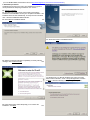
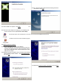
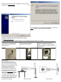
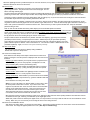
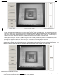
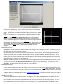
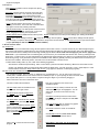
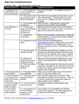
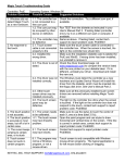
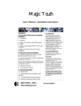
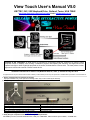
View Touch User’s Manual V5.0
KEYTEC, INC, 520 Shepherd Drive, Garland, Texas, USA 75042
http://www.magictouch.com/ViewTouch.html Email: [email protected]
Principle of the Technology: A digital sensor is connected to a computer’s USB port, and set up to view the entire
projection screen or display. After running a calibration program and adjusting the sensitivity, the digital sensor can
capture laser light or other bright light projected on the screen, and translate to a mouse click. The laser pointer or other
light source can thus be used as a mouse control device.
Installation instructions for Version 5.0 (Windows 2000, XP, Vista, 7) Revised on July 22nd 2010
All rights reserved. No part of this document and the software provided with the product may be reproduced or modified without permission of the manufacturer.
1. Please read and follow all instructions carefully.
Improper installation may cause permanent damage, which may not be covered by the warranty.
2. Verify that you received all of the parts on the following parts list:
1pc Digital Light Sensor (Part No. VT-DS)
1pc Tabletop Tripod (Part No. VT-TP)
1pc Dual Level Laser Pointer (Part No. VT-LS)
1pc Installation CD (Part No. VT-CD)
1pc Ring - for yellow button hold-down (Part No. VT-LSR)
1pc User’s Manual (Part No. VT-UM)
2pcs spare laser pointer tips (Part No. VT-LST)
2pcs AA Batteries
2pcs laser pointer extension rods (Part No. VT-EX)
1pc Warranty Card
If any part is missing, please email [email protected] for assistance.
3. Verify that your computer meets the Minimum System Requirements:
PIII 850MHz processor, Windows 2000/XP/Vista/7, USB port, 128MB RAM, 1MB Hard Drive space available, CD-ROM drive.
(If no CD-ROM available, download the driver at http://www.magictouch.com/ViewTouch-download.html.)
4. Installation procedures
Uninstall previous View Touch (if any) from add/remove program in
control panel before attempting to install the new revision.
4.1 Software Installation
4.1.1 DO NOT plug in light sensor before finishing the software
installation. Insert installation CD into your computer’s CD-ROM. If the
installation does not start automatically, run setup.exe from CD-ROM
drive. Windows InstallShield Wizard will start.
4.1.2 Click Next in InstallShield Wizard.
>>>
<<< 4.1.3 Click Install in InstallShield Wizard.
4.1.4 When prompted by Windows compatibility or security warning
message, click Continue Anyway.
>>>
<<< 4.1.5 If there is no DirectX installed in the system, the setup
wizard for DirectX will start. Check I accept the agreement, and then
click Next. If DirectX is already in the system, go to step 4.1.8.
4.1.6 The DirectX setup wizard will prompt you to continue the
installation. Click Next.
>>>
<<< 4.1.7 The DirectX setup wizard will finish installing the DirectX
components. Click Finish.
4.1.8 The installation is complete. Click Finish.
>>>
4.1.9 Two View Touch utility icons are placed on your desktop: View
Touch and View Touch Pen (see 5.3 View Touch Setup)
<<< Runs the View Touch Control Panel. From here, you can set up and calibrate the View Touch.
<<< Runs the View Touch Pen annotation program.
4.2 Digital Light Sensor installation
4.2.1 Plug the digital light sensor into a free USB port.
Should the USB cable of the sensor be too short to reach your
computer, the following have been tested successfully with the
View Touch’s digital light sensor: Powered USB hubs or Active
USB extension cables
4.2.2 Windows may either update the driver information automatically or
start Found New Hardware Wizard. Check Yes. This time only,
>>>
then click Next.
<<< 4.2.3 Check Install the software automatically, then click Next.
4.2.4 When prompted by Windows compatibility or security warning
>>>
message, click Continue Anyway.
<<< 4.2.5 When the Found New Hardware Wizard is complete, click
Finish. Continue to step 5. Setup and Calibration.
5. Setup and Calibration (An instructional DVD is included)
5.1 Digital Light Sensor Setup
5.1.1 Mounting: There are three standard methods to mount the digital light sensor: tripod, clip, or ceiling.
Tripod mounting - Either a standard
Clip mounting - The digital light sensor
Ceiling mounting - The digital light sensor
camera tripod, or the tabletop tripod
can be clipped onto a notebook
can be mounted upside down on the
provided can be used to mount the
computer or any rigid board.
ceiling. An extension bar may be needed
digital light sensor.
to lower the sensor to be within 15 degree
of the center line.
5.1.2 Positioning
When positioning the sensor, the
distance between the screen and the
sensor must be at least approximately
twice the width of the projected image.
For example: If the width of the
projected image is 5 feet, then the
sensor needs to be positioned about
10 feet away from the screen in order
“see” the entire screen. There is a
window in the setup program showing
exactly what the sensor sees to help
you position the sensor correctly.
For best results, the digital light sensor
should be positioned within 15° along
the center line of the screen (both
vertically and horizontally).
to
View from the side
View from above
When the digital light sensor is positioned beyond 15° from the center line, it may result in increasingly uneven sensitivity due to the uneven
distances between the sensor and the screen.
5.2 Laser Pointer
The laser pointer was designed for two-button use as well as direct activation
by touching the screen. The yellow button emits low-intensity light. The red
button emits high-intensity light.
The low-intensity laser light (yellow button) is used as a guiding light allowing the user to aim at an icon, button or hyper link before
performing a mouse click. Once the object is within aim, the high-intensity laser light (red button) is pressed to activate the mouse click.
A black ring holder is included to keep the yellow button down by pushing it up, so you do not need to use one finger to control two buttons.
Do remember to pull down the ring to release yellow button after use.
Hold the laser pointer comfortably in whichever hand you wish to. During normal operation, the yellow button will be pressed down by the
ring holder to emit low-intensity light to aim at icons, buttons, hyper links, and so on. Once the low-intensity light is centered on the item you
wish to click, press the red button to activate the mouse click. Press it twice if you wish to perform double-click. Keep the red button
pressed to drag or draw.
Note: In order to make double click easier, please adjust your mouse double speed to the lowest.
The plastic activation tip can be used to touch the screen directly like a mouse pen. When the tip is touched to the
screen, a left mouse click occurs. For optimum accuracy, the buttons on the pointer should be pointed up (like you
were going to press them), otherwise the laser will not line up with the point where the tip touches. To drag, keep
the tip pressed to the screen and drag along the surface of the screen.
The tip is made of Teflon and should be very durable. Should it need replacing, grip the tip and unscrew it
(clockwise) from the housing. Two spare tips are included. Additional tips may be purchased separately.
This model also comes with extension rods, which screw into the back end of the pointer allowing use of the
plastic activation tip from a distance. Each rod measures 12”. Two rods are included. Additional rods can be
purchased separately. Again, the buttons on the pointer should be pointed up.
5.3 View Touch Setup
The View Touch icon was placed on desktop during installation.
Double-click to open the setup screen.
5.3.1 View Touch Setup Screen
Each selection of the Setup screen helps to define how the View Touch
system is arranged. This setup screen is displayed each time View Touch
is started.
Display Type: Select whether your computer screen is projected onto a
screen/wall - specify front or rear projection; or displayed on a LCD,
CRT, or Plasma (PDP) monitor (see following notes).
Sensor Orientation: Select whether the digital light sensor is mounted
Upside down or Upside up. (ceiling mounting can result in an upside
down orientation).
Sensor Location: Select whether the digital light sensor is located in front
of the screen or behind it – if rear projection screen is used.
Startup Automatically: Select whether you want the View Touch software
starts automatically on computer start-up. (previous calibration data will
be loaded)
Once selections are made, press “Start!”
Note: If you use a flat-panel LCD, Plasma (PDP) or CRT monitor, shine
the laser pointer at the monitor’s screen. If you cannot see a clear,
bright red dot, then the View Touch will not be able to see the dot either
and will not be usable with the monitor. View Touch should work on
most PDP and CRT monitors due to their reflective glass surfaces.
Some flat-panel LCDs have a protective piece of glass in front of the
LCD element, which should be suitable for the View Touch.
Most projection screens should be suitable for View Touch, although screens that have been specially treated for anti-reflective surfaces
will absorb the laser light, rendering it undetectable by the digital light sensor.
While laser pointer cannot be viewed by the digital sensor, it is still possible to use a stylus with red LED to touch and activate the screen
directly. Make sure your arm and body is not blocking the sensor from seeing the LED.
5.3.2 View Touch Calibration Screen
After clicking the ‘Start!’ button, you will see the screen below. The picture-in-picture window in the center of the screen shows what the
sensor sees. The image will appear pinkish-red in color. (See step 5.1.5 Positioning)
Button column
Picture-in-picture window
Sensitivity adjustment bar
Concerning bright spots…
Try to avoid bright spots appearing on the screen image, whether caused by nearby lamps, light fixtures, light from the
projector, or other sources of strong light in the room. The View Touch works when the light sensor is drawn to the brightest
spot on the screen…which should be the red dot of the laser pointer. If some other source of light (ex. A nearby lamp) is
present on the screen; the sensor will become ‘fixated’ on it, causing the cursor to ‘stick’ to the bright spot.
Should a bright spot occur, you may be unable to use your mouse normally (since the light sensor is constantly drawing to the
bright spot). To free your cursor, simply block the light sensor from viewing the screen (put your hand over it). Then, adjust
the angle of the projector or the screen, lower room lights, or move lamps until the bright spot is removed.
Once the displayed image has been adjusted and centered within the picture-in-picture window, perform a quick test to
ensure that the sensor can see the entire screen. Point the laser pointer at the four extreme corners of the screen. The
laser’s red dot will appear as a bright, white spot within the picture-in-picture window, like seen below:
5.3.3 View Touch Calibration Procedure
To begin the calibration process, click Calibration from the column of buttons on the left. A black and white grid image will flash on your
screen for a few seconds then return to the Calibration screen, like below:
Using your mouse, place the cursor at the center of each cross point of the grid (9 total) then
click to place the calibration point. Start at the upper-left corner and continue clockwise
around the figure, as depicted in the sequence to the right, finishing in the center of the
pattern. If the sequence is not followed correctly, the calibration will be incorrect. Calibrate
again.
If you incorrectly place a point, or accidentally place multiple points instead of one, click
Cancel, then click Calibration to start again. After all 9 cross points have been clicked, click
OK to finish. Proceed to step 5.3.4 Adjusting Sensitivity to set the sensitivity levels.
Note: If you cannot see the entire grid pattern, either the sensor cannot see the entire
screen, or the ambient lighting is too strong resulting in a ‘washed out’ image. Click Reset
and make the necessary adjustments, then click Calibration to start again.
After calibration, the image in the picture-in-picture window darkens. Once the image is dark,
the laser pointer will be able to activate the mouse. If you need to adjust the digital light
sensor’s position, click Reset to return to brighter image and calibrate again after
adjustment.
5.3.4 Adjusting Sensitivity
After calibration, you will need to set the sensitivity level for the laser pointer, located at the right of the screen. The brighter the room, the
higher the sensitivity will need to be set. It is recommended to begin testing with the sensitivity set at its midpoint. The sensitivity bar can
be adjusted using your mouse or up/down arrow keys.
As described in step 5.2, the View Touch laser pointer is designed with two levels of intensity. The low-intensity light (yellow button) is
used as a guiding light, so you can see where the laser pointer is pointing. As such, it should NOT activate the mouse cursor. Only the
high-intensity light (red button) should activate the mouse (perform a mouse click). Point the laser pointer at the screen and test both
intensity levels. The sensitivity level is set correctly when the high-intensity light (red button) is consistently activating the mouse, and the
low-intensity light (yellow button) is consistently ignored. If you plan on ONLY using the laser pointer’s plastic activation tip, then it is not
necessary to adjust the sensitivity for the low-intensity light.
Note: Keep adjusting the sensitivity until you can move the high-intensity light (red button) at a comfortable speed without losing the track
of mouse cursor movement. (See Step 5.3.5 Setting Speed Level to adjust View Touch speed settings). Check the accuracy of the
cursor position versus the laser spot position. If it is not accurate enough, try calibrating again. (See step 5.3.3 View Touch Calibration
Procedure). Test the sensitivity at the extreme edges and corners of the image
5.3.5 Setting Speed Level
Once the sensitivity is correctly set and the accuracy is satisfactory, the View Touch is ready for operation. There are three speed levels
you can choose by clicking the top button in the left button column. Pressing the top button cycles the speed between the different levels:
Super Smooth, Smooth and Fast. If your application typically uses point and click only, select Fast for faster cursor response. If you want
to perform more smooth drawing or writing with the View Touch, then select Super Smooth. Select Smooth for a compromise between the
two other modes.
A KEYTEC Magic Touch screen (information available at http://www.magictouch.com/) can also be used to further enhance any drawing or
writing capabilities.
5.3.6. Multi-Touch Option
View Touch supports Windows 7 multi touch function. After calibration, you will see an “Enable Multi” button at the bottom right of the
window. You can click to enable and click again to disable.
Once it is enabled, open Windows paint program, test it with 2 laser pointers to see if you can draw 2 lines simultaneously. You can use
more than 2 laser pointers to run multi-touch programs. However, the computer speed needs to be fast enough to operate more touch
points simultaneously. The response time is slower in multi touch mode, so you may want to disable it when you use View Touch for a
single touch program.
5.3.7 Options
Click Options in left button column will open the options
window as shown
>>>
Move only: The laser pointer moves the cursor, but does
not perform mouse click . This mode may be used with a
presentation laser mouse (not included) which has RF
controlled buttons. Use the laser mouse to move the cursor.
Once the cursor hits the target, release the laser button to
turn off the laser and press the mouse control button to click.
Lift off: The laser pointer will move the cursor without
activating mouse click. The mouse click is activated when
laser light is turned off by releasing red button.
Normal (default setting): The laser pointer moves the cursor
and activate left mouse click at same time. Only in this
mode, dragging and drawing can be performed.
Disable (default setting): Disable the auto start-up mode. Enable: Enable View Touch with previous settings upon starting the Windows.
Default: Return all the settings to default. OK: Accept all the settings and exit options. Cancel: Cancel all the settings and exit options.
After the setup is completed, click Minimize to minimize the setup screen into the task bar, or click View Touch Pen to open the annotation
program (See Step 6.2 View Touch Pen Annotation Software).
6. How to use View Touch
6.1 General Use
Once the View Touch is loaded and running, the laser pointer functions like a mouse. You point the laser at your desired target using the
low-intensity (yellow button) guiding light, then press the high-intensity light (red button) to perform the mouse click on the desired target.
The mouse cursor doesn’t visually move until the high-intensity light is clicked. All the same rules that apply to your mouse, apply to the
View Touch. If you must double-click on something with your mouse, then you must double-click with the View Touch by pressing the red
button twice. To drag an item, you click and hold down the high-intensity light (red button), the same as you would hold down the left mouse
button during a drag. It may be easier to practice at short distances first, and then gradually increase your distance from the screen as you
become more confident. With some practice, the View Touch can be used like a wireless mouse.
To make double-clicking easier, try one or both of the following suggestions:
Slow down the double-click speed setting. Start > Control Panel > [Printers and Other Hardware] > Mouse and move slider to slow.
Change your Windows options to accept single-clicks instead of double-clicks. Go to My Computer > Tools > Folder Options > Click
Items as follows and click on Single Click to open an item. (only applies to Windows, not third-party programs)
6.2 View Touch Pen Annotation Software
The annotation program, View Touch Pen, is designed to be a presentation tool. You can open it from View Touch
control panel, or double-click the View Touch Pen icon on desktop to open it. Upon opening, the View Touch Pen looks
like a square with a pen in it. You can position it anywhere along the edges of your screen by dragging it.
Click on the View Touch Pen to extend the menu.
This menu contains the tool buttons:
This menu contains the View Touch Pen’s
annotation options:
The Pen button shows the annotation menu
buttons shown in the right column.
Click on the Pen (2nd button) to extend color and
width selections for pen and highlighter. You can
draw, mark, and write on the screen over any
program.
The Mouse button extends to Right click,
Move only, Lift off and Normal modes (see
5.3.7)
The Speed button extends to Fast, Smooth,
and Super Smooth (see 5.3.5)
Power Point Control Buttons include: Home
returns to the first slide, Left point arrow
goes to previous slide, Right point arrow
goes to next slide, End advances to the last
slide, and End PPT will exit the slide show.
Click Save (3rd button)to save the entire screen
(annotations and all) as a snap shot in either BMP
or JPG format.
Use Undo and Redo like you would in any graphic
editing or word processing program.
Click Trash to clear the screen of annotations.
Click the Return Arrow to return to the mouse
control menu shown in the left column.
Click on the X to close the View Touch Pen
program.
Note: When in Pen mode, the mouse functions
are disabled.
The View Touch can be used in conjunction with your standard mouse and keyboard, as well as other useful software utilities such as onscreen keyboards and handwriting recognition software. It can also be used concurrently with KEYTEC’s Magic Touch screens for further
writing/drawing enhancement. More information available at www.magictouch.com.
6.3. Using View Touch in PowerPoint Presentations
When using View Touch with PowerPoint, it is recommended that the Slide Transition Advance setting (Slide Show -> Slide Transition ->
Advance) be changed so “On mouse click” is not selected. Click ‘Apply to All Slides’ to make the change universal. Changing this
setting allows you to use View Touch to draw the audience’s attention to a certain area of a slide (and write, draw, or point) without
advancing to the next slide accidentally. By default, PowerPoint is set to advance slides with a mouse click. Once “On mouse click” has
been unselected, it will be necessary to use either the PowerPoint tools displayed on each slide (lower-left corner), or use the presentation
and annotation tools of the View Touch Pen software. (See Step 6.2 View Touch Pen Annotation Software for details)
6.4. Using View Touch in Handwriting Recognition and On-Screen Keyboard
Microsoft Word has included handwriting recognition feature which converts the handwriting into text. In Write Anywhere mode, you can use
View Touch or a touch screen to write anywhere within a Word page and your writing will become text. You can also insert a drawing or use
on-screen keyboard to “type” with View Touch.
Windows 7 and Vista has a built-in handwriting and on-screen keyboard that you can use it with View Touch.
6.5. Using View Touch with a Presentation Laser Mouse (instead of the laser pointer included)
The View Touch light sensor can also be used with presentation remote mouse that has a built-in laser pointer. Since
the View Touch's default setting activates a mouse click when the laser is detected, it is necessary to open the Options
window (5.3.7) change the setting to “Move only” mode first.
Press the laser button to use laser pointer to move the cursor to the target. Release the laser button to turn off the
laser. The cursor is staying at the target and will not be affected by the movement of the laser mouse. Click the
mouse button to activate the mouse click. You will need to hold down the laser button and left mouse button
simultaneously in order to perform drag and draw.
6.6. Using View Touch with Standard Laser Pointer
The dual intensity laser pointer included with View Touch allows the user be able to aim and click. However, when
aiming is not necessary, then any standard laser pointer can be used. For example, a rear projection is used and the
user will be right in front of the screen, so he/she can use any laser pointer as a pen or stylus to point and click. If the
application does not have any small-size icon or button to be clicked, then a standard laser point may work just fine.
6.7. Using View Touch in Shooting Games
You can use View Touch to play any computer games as long as they are compatible with mouse. Shooting games are particularly suitable
for View Touch. You can use any laser pointer or laser toy gun to play with. However, if the game involves using cursor movement to
change the directions, and left click to activate shooting, it will be better to use a presentation laser mouse and set View Touch Options at
“move only” (6.5). You can use the laser to move the direction without shooting, but use the mouse button on the laser mouse to activate
shooting.
7. Troubleshooting
7.1 Error message when opening View Touch: “No video capture device was detected on your system”
- Make sure that the digital light sensor is connected to your computer’s USB port
- Make sure the digital light sensor is plugged into the same USB port you first installed it into. To use the View Touch on a different port than
the one originally installed into, perform the installation steps again, starting at Step 4.2 Digital Light Sensor Installation.
- This message can appear if View Touch is already running when the desktop icon is double-clicked. Do not double-click on the desktop icon to
reopen it. The running program is minimized to your task bar, click on it to maximize.
- If you are using a USB extension cable, make sure that it is rated for the length and distance you are using for it. Note: We recommend
“active” USB extension cables or powered USB hub.
7.2 Cannot get viewed image into picture-in-picture window
- No matter how you adjust the sensor’s distance and angle, you cannot get the viewed image into the window. This problem is seen on a few
notebook computer models when the video output mode is set to display on both the notebook’s built-in LCD panel and through the projector.
Toggle through the video output modes until the video is output to the projector only.
- Check if any other video capture devices are actively running on your computer, close or disable them.
- If you are using a USB extension cable, make sure that it is rated for the length and distance you are using for it. Note: We recommend
“active” USB extension cables or powered USB hub.
7.3 Not accurate after calibration
- No matter how carefully you calibrate, the mouse cursor is still far off from your laser pointer. This problem is seen on a few notebook
computer models when the video output mode is set to display on both the notebook’s built-in LCD panel and through the projector. Toggle
through the video output modes until the video is output to the projector only.
7.4 Cannot see the complete calibration grid
- If only part of the grid is missing, you may need to adjust the digital light sensor angle or increase the distance to the screen in order to view the
entire screen.
- If part of the grid is obscured by a white splotch and cannot be seen, it is likely that the View Touch is being affected by strong lighting. Try to
dim the lights, click Reset and try again.
7.5 The cursor is stuck to the edge of the screen
- Check the vicinity of the screen for any reflective material (such as the screen’s metal frame), or lights (such as the monitor’s power indicator
LED)
- Cover them to free the cursor.
7.6 The cursor is stuck in the middle of the screen
- Check for a bright spot on the screen.
- A common source is the projector’s beam of light. To fix this problem, adjust the angle and/or height of the projector until the brightest
point of the beam is directed out of the light sensor’s viewing area.
- Some projector screen fabrics may be too reflective. A change of screens may be necessary.
- If projected onto a wall, check the wall for hangings or remnant tacks/nails. Remove them to free the cursor
7.7 Cannot see the low-intensity guiding light
- The guiding light is weak by design. It may take a little while for your eyes to adjust to it.
- The light is seen easier in dimly lit rooms and against screen colors that provide good contrast.
- The light grows weaker when the pointer’s batteries run low. Change the batteries.
7.8 The mouse control function is not sensitive enough
- If the ambient lighting has changed since the last time the sensitivity levels were adjusted, it might be necessary to readjust the levels.
- The sensitivity levels just may not be set for optimal performance. Try fine tuning the sensitivity settings using the arrow keys on your
keyboard.
- The batteries may be low. Change them.
7.9 The View Touch is not sensitive on part of the screen
- While some uneven sensitivity is to be expected when the light sensor is positioned away from the center line of the screen, complete
insensitivity of a part of the screen is unacceptable. Make sure that the sensor is not positioned at greater than 15° from the center point of the
screen in either the horizontal or vertical axis.
- Check if the sensor’s lens is dirty or covered by dust.
7.10 The View Touch stops responding after I change the display resolution, or the display resolution is changed by a running application
- Maximize the View Touch from the task bar, and test with laser pointer for cursor response. If the mouse follows, then minimize the View
Touch and continue use.
- If the mouse does not follow, exit the View Touch software. Unplug the light sensor’s USB cable and plug it back in. Start the View Touch
again and click Load Calibration. If the offset between laser light and mouse cursor is too big, click Reset, then click Calibration to recalibrate the
View Touch.
For assistance, please contact KEYTEC:
- Email: [email protected]
- Phone: 800-MAGIC-89 or 972-272-7555 (9am-5pm CST, Monday through Friday)
8. Warranty: LIMITED ONE-YEAR PARTS AND LABOR WARRANTY
KEYTEC will supply, at no charge, new or a rebuilt part in exchange of the defective one for a period of one year from the date of purchase.
You must first notify KEYTEC'S technical support dept. by sending an email to [email protected] or calling 800-MAGIC-89 or 972-272-7555
(9AM-5PM, CST, Monday to Friday) to report the problem. If the technical support personnel have determined that your Magic Touch product
needs to be serviced, you will be given a RMA# (Return Merchandise Authorization Number) for sending your product in for service. You must
deliver the product freight prepaid in the original package or package with equal degree of protection to the authorized service station as
instructed by technical support department. The RMA# must be clearly marked outside of the package. Your return address must be included.
If the product is out of the warranty, you will be quoted for the replacement or repair cost. No work will be performed until your approval on all
the charges is confirmed.
WHAT'S NOT COVERED?
Products that have been previously altered, repaired or serviced by unauthorized personnel, or serial number on the products has been altered
or removed, or cosmetic damages and physical damages, or damages due to improper installation, operation or connection to improper voltage
supply, or any damages due to misuses, abuses, negligence, unauthorized modifications, accidents and acts of God, or those products which
were sold AS IS or WITH ALL FAULTS.
9. Please send your comments, compliments or complaints to [email protected].
FCC COMPLIANCE
This equipment has been listed and found to comply with the limits for a Class B digital device, pursuant to Part 15, Subpart B of FCC Rules.
This equipment generates, uses, and can radiate radio frequency energy. If not installed and used in accordance with the instructions, it may
cause interference to radio communications. The limits are designed to provide reasonable protection against such interference in a residential
situation. There is no guarantee that interference will not occur in a particular installation.
DISCLAIMER
The material in this document is for an informational purpose and is subject to change without notice. The manufacturer assumes no
responsibility for errors or omissions in this document. Nor are any liability assumed for any damages from the use of this product and the
information contained in this document. All mentioned product names herein are registered trademarks of the respective companies.
REGISTERED TRADEMARKS
KEYTEC, VIEW TOUCH and MAGIC TOUCH are registered trademarks of KEYTEC, INC.