1
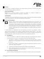
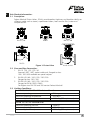
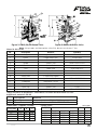
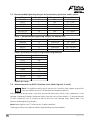
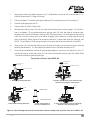
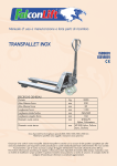
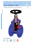
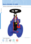
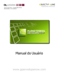
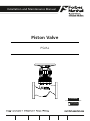
Installation and Maintenance Manual
Piston Valve
PSVAL
ProductHUB
Installation and Maintenance Guide
ANDROID APP ON
G oogl e play
Forbes Marshall
Forbes Marshall Arca
Codel International
Krohne Marshall
Forbes Solar
Forbes Vyncke
Forbes Marshall Steam Systems
Table of Contents
1.
Preface .................................................................................1
2.
Important Safety Notes .........................................................1
3.
Brief Product Information ......................................................3
4.
Operation ............................................................................11
5.
Installation Guidelines ........................................................11
6.
Start-up and Commissioning ...............................................12
7.
Maintenance Guidelines .....................................................12
8.
Troubleshooting ..................................................................19
9.
Available Spares .................................................................21
10.
Warranty Period ..................................................................21
PLEASE NOTE - Throughout this manual this cautionary symbol is used to
describe a potential damage or injury that might occur if the safety
considerations are overlooked. This symbol denotes CAUTION, WARNING or
DANGER.
Piston Valve
1.
Preface:
This manual is intended for anyone using, commissioning, servicing, or disposing the below
mentioned products safely and efficiently.
Piston Valve [PSVAL]
Size: DN15 (½”) / DN20 (¾”) / DN25 (1”) / DN32 (1 ¼”) / DN40 (1 ½”) / DN50 (2”) / DN65 (2 ½”) /
DN80 (3”) / DN100 (4”) / DN125 (5”) / DN150 (6”) / DN200 (8”)
PLEASE NOTE:
Throughout this manual the following cautionary symbol is used to describe a potential damage
or injury that might occur if the safety considerations are overlooked.
2.
Important Safety Notes:
Read this section carefully before installing/operating/maintaining the product. The
precautions listed in this manual are provided for personnel and equipment safety.
Furthermore, Forbes Marshall accepts no responsibility for accidents or damage
occurring as a result of failure to observe these precautions. Note that the product is
designed to perform for non-contaminated fluids only. A contamination in the form of
chemical, foreign particle etc. can lead to problem with product performance and life
of the product.
If these products in compliance with the operating instructions are, properly installed,
commissioned, maintained and installed by qualified personnel (refer Section 2.7) the safety
operations of these products can be guaranteed. General instructions for proper use of tools and
safety of equipments, pipeline and plant construction must also be complied with.
2.1 Intended use:
Check if the product is suitable for intended use/ application by referring to the installation
and maintenance instructions, name plates and technical information sheets.
i)
The product is suitable for use as defined in the technical information sheet. In case the
need arises to use the product on any other fluid please contact Forbes Marshall for
assistance.
ii)
Check for the suitability in conformance to the limiting conditions specified in technical
information sheet of the product.
iii)
The correct installation and direction of fluid flow has to be determined.
iv)
Forbes Marshall products are not intended to resist external stresses, hence necessary
precautions to be taken to minimize the same.
2.2 Accessibility and Lighting:
Safe accessibility and working conditions are to be ensured prior to working on the product.
PSVAL
1
2.3 Hazardous environment and media:
The product has to be protected from hazardous environment and check to ensure that no
hazardous liquids or gases pass through the product.
2.4 Depressurizing of systems and normalizing of temperature:
Ensure isolation and safety venting of any pressure to the atmospheric pressure. Even if the
pressure gauge indicates zero, do not make an assumption that the system has been
depressurized. To avoid danger of burns allow temperature to normalize after isolation.
2.5 Tools and consumables:
Ensure you have appropriate tools and / or consumables available before starting the work.
Use of original Forbes Marshall replacement parts is recommended.
2.6 Protective clothing:
Consider for the requirement of any protective clothing for you/ or others in the vicinity for
protection against hazards of temperature (high or low), chemicals, radiation, dangers to
eyes and face, noise and falling objects
2.7 Permits to work:
All work to be carried out under supervision of a competent person. Training should be
imparted to operating personnel on correct usage of product as per Installation and
Maintenance instruction. “Permit to work” to be complied with (wherever applicable), in
case of absence of this system a responsible person should have complete information and
knowledge on what work is going on and where required, arrange to have an assistant with
his primary goal and responsibility being safety. “Warning Notices” should be posted
wherever necessary.
2.8 Handling:
There is a risk of injury if heavy products are handled manually. Analyze the risk and use
appropriate handling method by taking into consideration the task, individual, the working
environment and the load.
2.9 Freezing:
Provision should be made to protect systems which are not self-draining, against frost
damage (in environment where they may be exposed to temperatures below freezing point)
to be made.
2.10 Returning products:
Customers and Stockist are reminded that, when returning products to Forbes Marshall they
must provide information on any hazards and the precautions to be taken due to
contamination residues or mechanical damage which may present a health, safety or
environmental risk.
This information must be provided in writing including Health and Safety data sheets
relating to any substances identified as hazardous or potentially hazardous.
2
Piston Valve
3.
Brief Product Information:
3.1 Description:
Forbes Marshall Piston Valves, PSVAL, provide perfect tightness and durable stability on
different media such as steam, superheated steam, heat transfer fluid, water and
compressed air.
DN 15 / 20
DN 25
DN 32 / 40
Figure 1: Piston Valve
DN 65 to 200
DN 50
3.2 Sizes and Pipe Connection:
1. DN 15 / 20 / 25 / 32 / 40
Screwed BSPT / NPT, socket weld ends, flanged to class
150 / 300 / 600 available on special request
2. DN 50 / 65 / 80 / 100 / 125 / 150 / 200
Flanged to class 150 / 300
3. DN 50 / 65 / 80 / 100 / 125 / 150 / 200
Flanged to PN16 / PN25 / PN40
For higher sizes DN 250 and 300 contact Forbes Marshall
3.3 Limiting Conditions:
For DN 15 / 20 / 25 / 32 / 40 Socket weld ends
Maximum operating pressure
Maximum operating temperature
Maximum hydraulic test pressure
78 bar g
425 deg c
156 bar g (IBR requirement)
For DN 15 / 20 / 25 Screwed ends
Maximum operating pressure
Maximum operating temperature
Maximum hydraulic test pressure
PSVAL
78 bar g
425 deg c
156 bar g (IBR requirement)
3
For DN 32 / 40 Screwed ends
Maximum operating pressure
Maximum operating temperature
Maximum hydraulic test pressure
41.5 bar g
425 deg c
83 bar g (IBR requirement)
Body design conditions : DN 15/20/25/32/40 Class 600 Flanged ends
Maximum allowable pressure
Maximum operating pressure
Maximum operating temperature
Maximum hydraulic test pressure
41.5 bar g
425 deg c
83 bar g (IBR requirement)
156 bar g
Body design conditions : DN 50-200 PN 16 Flanged End
Maximum allowable pressure
Maximum operating pressure
Maximum operating temperature
Cold hydraulic test pressure
16 bar g at 38 deg C
16 bar g at 204 deg C
425 deg C at 9.1 bar g
24 bar g
Body design conditions : DN 50-150 PN 25 Flanged End
Maximum allowable pressure
25 bar g at 38 deg C
Maximum operating pressure
25 bar g at 226 deg C
Maximum operating temperature
425 deg C at 14 bar g
Cold hydraulic test pressure
38 bar g
Body design conditions : DN 50-200 PN 40 Flanged End
Maximum allowable pressure
Maximum operating pressure
Maximum operating temperature
Cold hydraulic test pressure
40 bar g at 38 deg C
39 bar g at 250 deg C
425 deg C at 22.8 bar g
60 bar g
Body design conditions : DN 15-200 Class 150 Flanged ends
Maximum allowable pressure
Maximum operating pressure
Maximum operating temperature
Cold hydraulic test pressure
19.6 bar g at 38 deg C
14 bar g at 197 deg C
425 deg C at 5.5 bar g
28 bar g (IBR requirement)
Body design conditions : DN15-200 Class 300 Flanged End
Maximum allowable pressure
Maximum operating pressure
Maximum operating temperature
Cold hydraulic test pressure
4
51 bar g at 38 deg C
41.5 bar g at 253 deg C
425 deg C at 28.8 bar g
83 bar g (IBR requirement)
Piston Valve
Figure 2: DN15, 20, 25 Piston Valve
Figure 3: DN32, 40 Piston Valve
Note: Always open and close piston valve fully, do not use valve or ‘F key.
Material: DN 15-40:
No.
Description
Material
Standard
1
Body
Forged Carbon Steel
ASTM A105N
2
Bonnet
Forged Carbon Steel
ASTM A105N
3
Piston
Stainless Steel
ASTM A 276 TYPE 304
4
Spindle
Stainless Steel
ASTM A 276 TYPE 410
5
Nyloc Nut
Carbon Steel
6
Stud
Carbon Steel
ASTM A193 Gr. B7
7
Nut
Carbon Steel
ASTM A 194 Gr.2H
8
Belleville Washer
Spring Steel
50CrV4
9
Sealing stack
S.S. Reinforced Graphite
10
Spacer
Stainless Steel
11
*Handwheel
Sheet Metal / SG Iron
ASTM A 276 TYPE 410
12
Name Plate
Stainless Steel
13
Grease Cap
Stainless Steel
SS 304
14
Gap ring
Stainless Steel
ASTM A 276 TYPE 410
ASTM A 240 TYPE 304
*Note :For DN 15-25 Handwheel - Sheet Metal | For DN32-40 Hand wheel-S.G. Iron
Additional material: DN 40
Sr.No. Description
Material
15
Split Nut
Brass
16
Thrust Plate
Stainless Steel
Dimensions: (approx. in mm):
Size (DN)
A
B
C
15
20
25
32
40
PSVAL
110
110
126
165
165
118
118
133
175
175
146
146
165
215
215
DIN En12164
ASTM A 275 TYPE 420
Flange Class:
Size (DN)
*Tol ±1mm
A*
B
C
118
118
133
175
175
146
146
165
215
215
Class 150 Class 300 Class 600
15
20
25
32
40
252
252
260
305
305
265
265
278
317
317
265
265
278
320
320
5
Figure 4: DN50 Piston Valve
Note: Always open and close piston valve fully, do not use valve or ‘F key.
Material: DN 50
Sr. No.
Part
Material
Standard
1
Body
Cast steel
ASTM A 216 Gr. WCB
2
Bonnet
Cast steel
ASTM A 216 Gr. WCB
3
Piston
Stainless steel
ASTM A 276 Type304
4
Spindle
Stainless steel
ASTM A 276 Type410
5
Nyloc nut
Carbon steel
-
6
Stud
Carbon steel
ASTM A 193 Gr.B7
7
Nut
Carbon steel
ASTM A 194 Gr.2H
8
Belleville washer
Spring steel
50CrV4
9
Sealing Stack
S/S Reinforced Graphite
-
10
Spacer
Stainless steel
ASTM A 743 Gr.CA15
11
Handwheel
S.G. Iron
-
12
Split nut
Brass
DIN EN12164
13
Thrust plate
Stainless steel
ASTM A 276 Type420
14
Name plate
Stainless steel
ASTM A 240 Type304
15
Gap Ring
Stainless Steel
ASTM A276 TYPE 410
Dimensions (approx. in mm) : Size DN 50
ANSI
Class
6
No. of
Holes
T
E
F
Weight
19
4
19
210
262
14.5 kg
19
8
22
210
262
17.5 kg
125
18
4
18
210
262
14.5 kg
125
18
4
20
210
262
17.5 kg
L
D
PCD
150
203
152
121
200
267
165
127
PN 16/25
230
165
PN 40
230
165
H
Piston Valve
Figure 5: DN 65-200 Piston Valve
Note: Always open and close piston valve fully, do not use valve or ‘F key.
Material: DN 65-200:
Sr. No.
1
2
3
4
5
6
7
8
9
10
11
12
13
14
15
16
17
18
19
20
21
22
23
24
PSVAL
Part
Body
Bonnet
Piston
Body Sealing Stack
Spacer
Spindle
Stem
Split nut
LH Nut
Gland Sealing Slack
Threaded Bush
Back Seat
Hex. Gland Nut
Bonnet sealing stack
Stud
Nut
Belleville washer
Handwheel
Nyloc nut
Name plate
Thrust plate
Washer
Grub screw
Gap Ring
Material
Cast steel
Cast steel
Stainless steel
S/S Reinforced graphite
Stainless steel
Stainless steel
Stainless steel
Brass
Stainless steel
S/S Reinforced graphite
Ph. Bronze
Stainless steel
Stainless steel
Graphite
Carbon steel
Carbon steel
Spring steel
S.G. Iron
Carbon steel
Stainless steel
Stainless steel
Stainless steel
Hardened steel
Stainless steel
Standard
ASTM A 216 Gr. WCB
ASTM A 216 Gr. WCB
ASTM A 351 CF8
ASTM A 743 CA 15
ASTM A 276 Type 410
ASTM A 276 Type 304
DIN En12164
ASTM A 276 Type 304
ASTM A 276 Type410
ASTM A 276 Type410
ASTM A 193 Gr.B7
ASTM A 194 Gr.2H
50CrV4
ASTM A 240 Type304
ASTM A 276 Type420
ASTM A 240 Type304
I.S. 12.9
ASTM A 276 Type 410
7
Dimensions (approx. in mm) : Size DN 65 to 200
Sizes
(DN)
Pressure
Class
L
D
PCD
H
NO. OF
HOLES
T
E
F
Approx.
Weight
(Kg)
65
65
65
65
80
80
80
80
100
100
100
100
125
125
125
125
150
150
150
150
200
200
200
200
CLASS 300
CLASS 150
PN 16 / 25
PN40
CLASS 300
CLASS 150
PN 16 / 25
PN 40
CLASS 300
CLASS 150
PN 16 / 25
PN 40
CLASS 300
CLASS 150
PN 16 / 25
PN 40
CLASS 300
CLASS 150
PN 16 / 25
PN 40
CLASS 300
CLASS 150
PN 16
PN 40
292
216
290
290
318
241
310
310
356
292
350
350
400
356
400
400
445
406
480
480
559
495
600
600
191
178
185
185
210
191
200
200
254
229
220
235
280
254
250
270
318
279
285
300
381
343
340
375
149
140
145
145
168
152
160
168
200
191
180
190
235
216
210
220
270
241
240
250
330
298
295
320
22
19
18
18
22
19
18
18
22
19
20
24
22
22
18
26
22
22
22
26
25
22
22
30
8
4
8
8
8
4
8
8
8
8
8
8
8
8
8
8
12
8
8
8
12
8
12
12
25
22
18
22
28
24
24
20
32
24
18
22
35
24
22
26
37
26
22
28
41
28
24
34
335
335
335
335
320
320
320
320
395
395
395
395
446
446
446
446
486
486
486
486
591
591
591
591
400
400
400
400
384
384
384
479
479
479
479
479
540
540
540
540
598
598
598
598
728
728
728
728
31
27
27
31
37
31
31
37
58
47
47
58
87
70
70
87
117
90
90
117
210
164
164
210
8
Piston Valve
3.4
Operating Range:
DN50-200
425
The product must not be used
in this region.
A
300
200
A - B Flanged ANSI 150
A - F Flanged ANSI 300
* PMO- Maximum operating Pressure
100
B
F
0
10 14*
0
20
30
40 41.5*
51
Class 800
The product must not be used
in this region.
A - D Screwed and socket weld
Pressure barg
0
Temperature C
DIN PSVAL
425
400
The product must not be
used in this region.
300
Steam Saturation Curve
200
100
B
0
0
5
10
15
C
20
25
D
30
35
40
45
A - B Flanged PN 16
A - C Flanged PN 25
A - D Flanged PN 40
Pressure barg
PSVAL
9
Figure 6 : Exploded View of DN65-200 Piston Valve
10
Piston Valve
4.
Operation: [Refer figure 5]
The piston valve is operated manually by a handwheel (18) it should be either fully open or fully
closed. To open the piston valve turn the handwheel (18) in the anticlockwise direction until it
stops completely. To close the piston valve turn the handwheel (18) until it stop rotating further.
Note: The piston valve spindle should be periodically checked to ensure adequate
lubrication is present for efficient valve operation. For Lubrication 'Molykote M30'
lubricating oil is recommended. When fitted on high temperature applications or where
severe weather conditions prevail, the lubrication should be checked more frequently.
Note: Never tighten bonnet nuts when piston valve is in open condition. Do not use
piston valve for throttling which result in excessive wear of internals. Operation of the
handwheel (18) should always be by the hand, it is not recommended to use a valve key
or F key. If the handwheel is over-tightened, damage of the piston valve internals may
occur.
5.
Installation Guidelines: [Refer figure 7 and 8]
Note: Before implementing any installations observe the 'Important Safety notes' in
section 2. Referring to the installation and maintenance instructions, name – plate and
technical information sheet check the product is suitable for intended installation.
1.
The piston valve should be installed in the direction of fluid flow given by the arrow on the
body. The preferred orientation is with the spindle vertical with handwheel on the top. The
piston valve can be installed from the vertical to the horizontal plane.
Note: Do not install the piston valve with handwheel on lower side as maintenance or
lubrication of the piston valve will be difficult.
The preferred orientation for installation The valve can be installed in vertical pipework
Figure 7 : Correct orientation for installation
Figure 8 : Incorrect orientation for installation
PSVAL
11
2.
3.
4.
5.
6.
Adequate space should be available while installation of the piston valve so that they can be
conveniently operated and maintained.
Before installing a piston valve, check to ensure that the size, pressure rating, materials of
construction, end connections, etc. are suitable for the service conditions of the particular
application. Remove the cover plugs from the ports.
Note: Lubricate the product before installation as indicated if stored for more than
6 months.
Care must be taken to ensure before installing the piston valve that the line is clear
from all foreign particles such as welding fluxes, metal burr and dirt and maintain
cleanliness during installation since the introduction of foreign particles can result
in damage to the piston and sealing stack.
When a socket weld piston valve is being installed the welding should be carried
out to an approved procedure to a recognised standard. During welding the piston
valve should be in the open position to allow maximum heat dissipation.
Ensure that the discharged flow is directed to a safe place.
6.
Start-up and Commissioning:
6.1. Flushing of lines:
As part of pre-installation all fluid handling equipment particularly piping should be
thoroughly cleaned of scale and the internal debris which accumulates during construction.
This is accomplished by blowing or flushing with air, steam, water and other suitable
medium.
Note: For a detailed procedure on flushing of lines please visit Forbes Marshall website.
6.2. Commissioning:
After installation or maintenance ensure that the system is fully functioning by confirming
fluid is passing through it.
1. After flushing of lines is complete, open the piston valve fully by rotating handwheel in
anticlockwise direction.
2. Operation of the handwheel should always be by hand.
3. Check for leaks and attend if any.
7.
Maintenance Guidelines:
Note: Before undertaking any maintenance of the product it must be isolated from
both supply line and return line and ensure pressure is normalized to atmosphere. The
product should then be allowed to cool. When re-assembling ensure that all joint faces
are clean. Once completed open the product slowly and check for leaks.
12
Piston Valve
7.1. Routine and preventive maintenance:
Please refer to the maintenance schedule mentioned in the table below to undertake
routine maintenance of the piston valve.
PARAMETERS TO BE CHECKED
SR.
NO. PISTON VALVE
FREQUENCY FOR CHECKING VARIOUS PARAMETERS
Daily
Half
Weekly Monthly Quarterly yearly
1
Manually Operate the valve.
2
Lubrication of piston valves.
Y
3
Visual inspection and cleaning of stem-piston threads.
Y
4
Refilling of *Loctite Anti-Seize (in grease cap) for DN
15/20/25.
Annually
Y
Y
*Loctite Anti-seize threaded compound 767 high performance conforms to ML-A-907-E.
7.2. Tool Kit:
To carry out maintenance of the piston valve refer the tools mentioned in the table below. .
Sizes
DN15 /20/25
DN32/40/50
DN65/80/100/125
Component
Tool used & size
M 10 Stud
Stud runner M10 x 1.5
Nut
Box spanner of 17 mm (A/F)
Nyloc nut
Box spanner of 13 mm (A/F)
Sealing stack
Insertor tool (Available as spares)
Sealing stack
Extractor tool (Available as spares)
M12 Stud
Stud runner M12 x 1.75
Nut
Box spanner of 17mm (A/F)
Sealing stack
Insertor tool (Available as spares)
Sealing stack
Extractor tool (Available as spares)
M16 Stud
Stud runner M 16 x 2A
Nut
Box spanner of 24 mm (A/F)
Sealing stack
Insertor tool (Available as spares)
Sealing stack
Extractor tool (Available as spares)
M20 Stud
Stud runner M20 x 2
Nut
box spanner of 30mm (A/F)
Sealing stack
Insertor tool (Available as spares)
Sealing stack
Extractor tool (Available as spares)
M24 Stud
Stud runner M24 x 3
Nut
Box spanner of 36mm (A/F)
Sealing stack
Insertor tool (Available as spares)
Sealing stack
Extractor tool (Available as spares)
DN40/50/65/80
Split nut tightening
Open spanner of 20mm (A/F)
DN 100/125/150/200
Split nut tightening
Open spanner 24 mm (A/F)
DN 150
DN200
PSVAL
13
7.3. Recommended tightening torques for bonnet nuts, gland nuts and Kv values
Size
DN15/20
DN25
DN32/40
DN50
DN65/80
DN100/125
DN150/200
Part No.
7
7
7
7
16
16
16
Component
Nut
Nut
Nut
Nut
Nut
Nut
Nut
Torque Range
3 – 5 Nm
5 – 7 Nm
18 – 20 Nm
20 – 25 Nm
50 – 60Nm
70 – 80Nm
80 – 90Nm
Table 1 : Recommended tightening torques for bonnet nuts
Size
DN65/80
DN100/125
DN150
DN200
Part No.
13
13
13
13
Component
Gland Nut
Gland Nut
Gland Nut
Gland Nut
Torque Range
35 - 45Nm
75 – 85 Nm
80 – 90 Nm
95 – 110 Nm
Table 2: Recommended tightening torques for gland nuts
Size
DN15/20
DN25
DN32/40
DN 50
DN65
DN80
DN100
DN125
DN150
DN200
Kv Values
2.5
5.8
13
41
51
77
131
194
221
438
Table 3: Kv Values
7.4. Maintenance of size DN15 -50 piston valve : [Refer Figure 2, 3 and 4]
Note: The graphite sealing stacks contain thin stainless steel support rings which
may cause physical injury if not handled and disposed carefully.
Maintenance of piston valve is very easy and can be done when valve is not in operation. If any
leakage is observed through the bonnet hole, close the valve till handwheel (11) touches bonnet
(2) then tighten all nuts (7) equally by half or one turn until leakage stops. (Refer Table 1 for
recommended tightening torques).
Note: Never tighten nuts (7) when valve is in open condition.
If leakage still does not stop then follow the procedure mentioned below.
14
Piston Valve
1.
Keep piston valve fully open remove nuts (7) & Belleville washer (8) turn handwheel (11) in
clockwise direction till it stops at the top.
2.
Pull handwheel (11) carefully along with bonnet (2) to remove piston (3) from body (1).
3.
Avoid any damage to piston (3).
4.
Clean piston (3) with lint free cloth.
5.
Remove top sealing stack (9) with the help of extractor tool, remove spacer (10) [which is
free in the body (1)] and remove bottom sealing stack (9) with the help of extractor tool.
Replace with new set of bottom sealing stack (9), place spacer (10) and replace top sealing
stack (9) with the insertor tool. Use mallet to apply light strokes on insertor tool ensuring
they fit perfectly. (Refer figure 9 for extractor tool and insertor tool of piston valve for size
DN15 – 40 and figure 10 for extractor tool and insertor tool of piston valve for size DN50)
6.
Align piston (3) with the top sealing stack (9) and push gently and close the piston valve by
rotating handwheel (11) in the clockwise direction until it touches the bonnet (2).
7.
Ensure that the Belleville washer (8) are placed properly in cup form and tighten all nuts (7)
with equal torque when the piston (3) is at the end of bottom sealing stack (9). (Refer Table
1 for recommended tightening torque).
For piston valve of size DN15-40
PUSH GENTLY
BY HAND
PUSH GENTLY
BY HAND
EXTRACTOR TOOL
EXTRACTOR TOOL
2. Remove spacer which is free from the body
and then extract bottom sealing stack
1. Extract top sealing stack first
MALLET
MALLET
INSERTOR TOOL
INSERTOR TOOL
SEALING RING STACK
3. Insert bottom sealing stack first
4. Place sealing stack in
this way on Insertor tool
5. Place spacer which is free from the body
and then insert top sealing stack
Figure 9 : View showing extractor tool and insertor tool for sealing stack of piston valve of size DN15–40
PSVAL
15
For piston valve of size DN50
PUSH GENTLY
BY HAND
PUSH GENTLY
BY HAND
EXTRACTOR TOOL
EXTRACTOR TOOL
1. Extract top sealing stack first
2. Remove spacer which is free from the body
and then extract bottom sealing stack
MALLET
MALLET
INSERTOR TOOL
INSERTOR TOOL
INSERTOR TOOL
SEALING RING STACK
3. Insert bottom sealing stack first
4. Place sealing stack in
this way in insertor tool
5. Place spacer which is free from the body
and then insert top sealing stack
Figure 10 : View showing extractor tool and insertor tool for sealing stack of piston size of DN50
7.5. Maintenance of piston valve of size DN65-DN200 : [Refer Figure 5]
Note: The graphite sealing stacks contain thin stainless steel support rings which
may cause physical injury if not handled and disposed carefully.
Maintenance of piston valve is very easy and can be done when piston valve not in
operation. If any leakage is observed through the gland, tighten gland nut (13) to stop the
leakage through gland. If any leakage is observed through outlet or between the body (1)
and the bonnet (2) first close the valve till handwheel (18) touches the bonnet (2) then
tighten all nuts (16) equally by half or one turn until leakages stops. (Refer Table 1 for
recommended tightening torques)
Note: Never tighten nuts (7) when valve is in open condition.
If leakage yet does not stop then follow the procedure mentioned below.
16
1.
Keep piston valve fully open remove nuts (16) & Belleville washer (17) turns handwheel
(18) in anti- clockwise direction until it touches the bonnet (2). Pull handwheel carefully
along with bonnet (2) to remove piston (3) from body (1).
2.
In case the bonnet assembly does not come out of the body (1) use tapped hole for
removing bonnet assembly. Avoid any damage to piston (3).
3.
Clean piston (3) with lint free cloth.
Piston Valve
4.
5.
Remove body top sealing stack (4) with the help of extractor tool, remove spacer (5)
[which is free in the body (1)] and remove body bottom sealing stack (4) with the help of
extractor tool. Replace body bottom sealing stack (4), place spacer (5) and replace body
top sealing stack (4) with the insertor tool. Use mallet to apply light strokes on insertor
tool ensuring they fit perfectly. Insert bonnet sealing stack (14) carefully. (Refer figure 11
for extractor tool and insertor tool for piston valve of size DN65 – 200).
Place bonnet piston-spindle sub assembly on clean table.
6.
To replace gland sealing stack (10) remove nyloc nut (19) and handwheel (18). Hold
bonnet (2) by hand and remove spindle-piston sub assembly by rotating spindle (6) in
clockwise direction with the help of screw driver.
7.
Remove gland nut (13) and extract gland sealing stack (10) with extractor tool. Insert
new gland sealing stack (10) with the inserter tool. Use mallet to apply light strokes on
inserter tool ensuring they fit perfectly. (Refer Fig. 12 for extractor tool and insertor tool
for piston valve of size DN65 – 200). Screw gland nut (13) in the bonnet (2). Place
bonnet (2) on spindle-piston sub assembly and rotate spindle (6) in anticlockwise
direction until it stops.
8.
Align bonnet piston-spindle sub assembly in the body top sealing stack (4) and push it
gently. Place the handwheel (18) on the square of spindle (6), place name plate (21) and
nyloc nut (19). Place Belleville washer (17) in the cup form and hand tighten all the nuts.
Now rotate handwheel (18) in clockwise direction until it touches the bonnet (2). (Close
position of the valve).
9.
Tighten all the nuts (16) equally. Open isolation valve, if any leakage is observed through
the gland tighten gland nut (13). In case leakage is observed at the outlet or between
body face (1) and bonnet (2) tighten nut equally half or one turn as explained earlier.
For piston valve of size DN65 – 200
PULL
PULL
EXTRACTOR
EXTRACTOR
Spacer
1. Extract body top sealing stack first
2. Remove spacer (which is free
from the body)
3. Extract body bottom sealing stack
MALLET
MALLET
INSERTOR
Spacer
INSERTOR
INLET
5. Insert spacer (which is free)
bottom sealing stack first
6. Insert body top sealing stack
Fig. 114. :Insert
Viewbody
showing
extractor tool & insertor tool
for sealing stack of piston
valve of size DN65 - 200
from body
PSVAL
17
MALLET
INSERTOR
INSERTOR TOOL
EXTRACTOR
SEALING RING STACK
3. Extract gland sealing stack
2. Insert gland sealing stack
3. Place gland sealing stack in this
way in insertor tool
Fig. 12 : View showing extractor tool & insertor tool for gland sealing stack of piston valve of size DN65 - 200
7.6. Lubrication Procedure for Piston Valves of all sizes: [Refer figure 13]
Clean the valve unit before lubrication. For lubrication use *Molykote M30 lubricating oil.
For piston valve of sizes (DN15–50) lubricate spindle through the hole provided in the
bonnet and spindle threads on quarterly basis and for piston valve of sizes (DN 65-200)
lubricate between the spindle and threaded bush at the upper part of bonnet & stem and
spindle at the lower part of bonnet on quarterly basis asmentioned in section 9.
Note: *Molykote M30 lubricating oil is not available please use equivalent lubricating oil
with specification as shown in table 4.
Lubrication details DN65-200
Lubrication details DN15-50
Figure 13 : Lubrication for piston valve
18
Piston Valve
8.
Troubleshooting:
If the expected performance is unachievable after installation of the piston valve, check the
following points for appropriate corrective measures.
Failure Mode
Possible Cause
Remedy
Inadequate flow The piston valve is
Ensure the piston valve is completely open.
rate at outlet.
not completely open.
Fluid leakage
from end
connection.
End connection is
not tight.
Sealing stack worn
Fluid leakage
out.
from bonnet and
body.
Tighten the end connection with proper torque for
flange end and tighten the screwed end piston valve.
For piston valve of sizes DN15-50 if any leakage is
observed through bonnet hole, first close the valve till
handwheel touches bonnet and then tighten all the nuts
equally by half or one turn until leakage stops. (Refer
table 1 for recommended tightening torque.)
If leakage does not stop dismantle the valve, check if
sealing stack is worn-out. If worn-out replace with new
set of sealing stack.
Note: Never tighten nuts when valve is in open
condition.
For piston valve of sizes DN65 –200 if any leakage is
observed through the gland, tighten gland nut half or
one turn until leakage stops. To stop the leakage
between body and bonnet, first close the valve till
handwheel touches bonnet and then tighten all the nuts
equally by half or one turn until leakage stops. (Refer
table 1 for recommended tightening torque).
If leakage does not stop dismantle the valve, check if
gland sealing stack, bonnet sealing stack & body sealing
stack is worn-out. If worn-out replace with new one.
Note: Never tighten nuts when valve is in open
condition.
Piston is damaged or Check if piston is damaged due to scouring, corrosion of
the piston valve. If damaged replace with new piston kit.
corroded.
Excessive force is
Seizing of the piston
required to turn
valve.
the handwheel.
Lubricate the piston valve using *Molykote M30
lubricating oil on quarterly basis for sizes DN15- 50
lubricate spindle through the hole provided in the
bonnet and spindle threads and for sizes DN65-200
lubricate between the spindle and threaded bush at the
upper part of bonnet and stem and also spindle at the
lower part of the bonnet.
Note: Never attempt to modify the product. When replacing old parts with new parts, use the
spare parts listed in section 9.
*Molykote M30 lubricating oil is not available please use equivalent lubricating oil with
specification as shown in table 4.
PSVAL
19
Specification of Molykote M30
Colour
Black
Composition
Synthetic oil
Molybdenum disulphide
Dispersant
Density
Density at 20°C (68°F)
(Standard - DIN 51 757)
1.0 g/ml
Viscosity
Base oil viscosity at 40°C (104°F)
(Standard - DIN 51 562)
120mm3/s
Oil lubrication up to +200°C (397°F)
Temperature
Load –carrying
capacity, wear
protection.
Storage life
Service temperature range
Fourball
tester
(VKA)
Dry lubrication up to +450°C
(842°F)
Weld Load (Standard – DIN
51 562 pt.2)
2000 N
Wear scar under 800 N
(Standard – DIN 51 350
pt.3)
1.02 mm
Almen-Wieland machine
OK load.
20000 N
1 years
Table 4: Specification of Molykote M30
20
Piston Valve
9.
Available Spares: [Refer figure 2, 3, 4 and 5]
Always order spares part by using the description and Spare Code No. given below & stating size
Sr. No.
1
2
3
4
5
6
7
8
9
10
11
12
13
14
15
16
17
18
19
20
21
22
23
24
25
26
27
28
29
30
31
Spares
Set of sealing stack for DN15/20 piston valve
Set of sealing stack for DN25 piston valve
Set of sealing stack for DN40 piston valve
Set of sealing stack for DN50 piston valve
Set of sealing stack for DN65 piston valve
Set of sealing stack for DN80 piston valve
Set of sealing stack for DN100 piston valve
Set of sealing stack for DN125 piston valve
Set of sealing stack for DN150 piston valve
Set of sealing stack for DN200 piston valve
Inserter kit for DN15/20 piston valve
Insertor kit for DN25 piston valve
Insertor kit for DN32/40 piston valve
Insertor kit for DN50 piston valve
Insertor kit for DN80 piston valve
Insertor kit for DN100 piston valve
Insertor kit for DN150 piston valve
Insertor kit for DN125 piston valve
Insertor kit for DN65 piston valve
Insertor kit for DN200 piston valve
Extractor Tool for sizes DN15-DN200 piston valve
Piston spare kit for DN15/20 piston valve
Piston kit for DN25 piston valve
Piston kit for DN40 piston valve
Piston kit for DN50 piston valve
Piston kit for DN65 piston valve
Piston kit for DN80 piston valve
Piston kit for DN100 piston valve
Piston kit for DN125 piston valve
Piston spare kit for DN150 piston valve
Piston spare kit for DN200 piston valve
Part No.
9
9
9
9
4,10,14
4,10,14
4,10,14
4,10,14
4,10,14
4,10,14
Refer figure 9
Refer figure 9
Refer figure 9
Refer figure 10
Refer figure 11
Refer figure 11
Refer figure 11
Refer figure 11
Refer figure 11
Refer figure 11
Refer figure 9,10,11
3,4
3,4
3,4,18,19
3,4,12,13
3,6,7,8,9,12,20,22
3,6,7,8,9,12,20,22
3,6,7,8,9,12,20,22
3,6,7,8,9,12,20,22
3,6,7,8,9,12,20,22
3,6,7,8,9,12,20,22
Spare Codes
F3A2017591
F3A2017592
F3A2017678
F3A2017679
F3A2019470
F3A2017740
F3A2017741
F3A2019421
F3A2017742
F3A2017743
F3A2017990
F3A2017991
F3A2017992
F3A2017993
F3A2017994
F3A2017995
F3A2017996
F3A2019418
F3A2019433
F3A2019435
F3A2019471
F3A2017744
F3A2017746
F3A2017747
F3A2017748
F3A2017749
F3A2017750
F3A2017751
F3A2017752
F3A2017753
F3A2017754
How to Order:
Example: DN 15 Piston Valve with socket weld ends.
How to Order Spares:
Order spares as per the code no. specified in the user manual.
10. Warranty Period:
As per ordering information and agreements in the contract.
PSVAL
21
Forbes Marshall
B-85, Phase II, Chakan Indl Area
Systems Pvt. Ltd.
Sawardari, Chakan
(Formerly Spirax Marshall Pvt. Ltd.)
Tal. Khed, Dist. Pune 410501. INDIA. Opp 106th Milestone
Tel : +91 02135 393400
Email : [email protected]
Forbes Marshall Steam
Bombay Poona Road, Kasarwadi,
Pune 411 034. INDIA.
Tel.: 91(0)20-27145595, 39858555
CIN No : U27109PN1959PTC011334
www.forbesmarshall.com
Doc# FMSS/0415/UM-PSVAL/V1.R0
ALL CONTENTS HEREIN ARE THE PROPERTY OF FORBES MARSHALL PRIVATE LIMITED (“FMPL”) OR FORBES MARSHALL STEAM SYSTEMS PRIVATE
LIMITED (“FMSSPL”), AS THE CASE MAY BE, AND HAVING PROTECTION UNDER THE INTELLECTUAL PROPERTY RIGHTS. ANY REPRODUCTION,
DISTRIBUTION OR DISCLOSURE WITHOUT PRIOR WRITTEN PERMISSION IS PROHIBITED.
The information in this document is subject to change without notice. FMPL or its Subsidiaries, Associates, Affiliates and Group Companies assume no
responsibility for inaccuracies or omissions and specifically disclaim any liabilities, losses, or risks, personal or otherwise, incurred as a consequence,
directly or indirectly, of the use or application of any of the contents of this document.