1
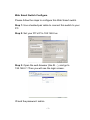
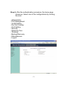
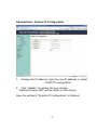
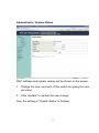
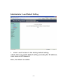
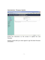
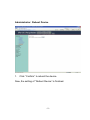
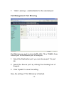
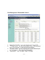
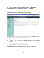
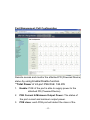
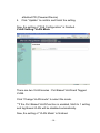
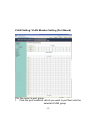
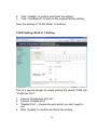
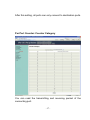
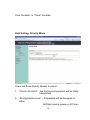
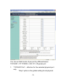
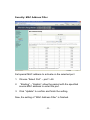
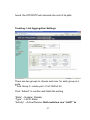
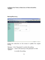
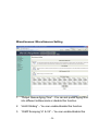
24 Port Nway Fast Ethernet PoE Web Smart Switch User’s Manual DN-95314 Web Smart Switch Configure Please follow the steps to configure this Web Smart switch. Step 1: Use a twisted pair cable to connect this switch to your PC. Step 2: Set your PC’s IP to 192.168.2.xx. Step 3: Open the web browser (like IE…), and go to 192.168.2.1 Then you will see the login screen. ID and the password: admin -1- Step 4: After the authentication procedure, the home page shows up. Select one of the configurations by clicking the icon. - Administrator - Port Management - VLAN Setting - Per Port Counter - QoS Setting - Security - Spanning Tree - Trunking - Backup/Recovery - Miscellaneous - Logout -2- Administrator: Authentication Configuration 1. Change the user name and the password. 2. Click “Update” to confirm the new change. Now, you can use the new user name and the password. -3- Administrator: System IP Configuration 1. 2. Change the IP address: type the new IP address or select DHCP IP configuration. Click “Update” to confirm the new change. “Setting Process OK!!” will be shown on the screen. Now, the setting of “System IP Configuration” is finished. -4- Administrator: System Status MAC address and system version will be shown on the screen. 1. Change the new comment of this switch by typing the new comment. 2. Click “Update” to confirm the new change. Now, the setting of “System Status” is finished. -5- Administrator: Load Default Setting 1. Click “Load” to back to the factory default setting. **Note: Recover switch default setting excluding the IP address, User name and Password. Now, the default is loaded. -6- Administrator: Firmware Update Follow the instruction on the screen to update the new firmware. Please contact with your sales agents to get the latest firmware information. -7- Administrator: Reboot Device 1. Click “Confirm” to reboot the device. Now, the setting of “Reboot Device” is finished. -8- Port Management: Port Configuration Select the “Port No.” - configure the mode below: 1. “Auto” - enable/disable Auto-Negotiation. 2. “Speed” - 10M or 100M mode for the selected port. 3. “Duplex” - Full or Half-Duplex mode for the selected port. 4. “Pause” - enable/disable for the selected port. 5. “Backpressure” - enable/disable for the selected port. 6. “Tx Capability” - enable/disable for the selected port. -9- 7. “Addr. Learning” - enable/disable for the selected port. Port Management: Port Mirroring Port Mirroring is used to mirror traffic, RX, TX or TX&RX, from Source port to Destination port for analysis. 1. Select the Destination port: you can choose port 1 to port 26 2. Select the Source port: by clicking the checking box of the port. 3. Click “Update” to save the setting. Now, the setting of “Port Mirroring” is finished. - 10 - Port Management: Bandwidth Control 1. 2. 3. 4. Select the “Port No.”: you can choose port 1 to port 26 “TX Rate Value”: set the transmission rate of the selected port. (0:Full speed; 1~255:Specified bandwidth.) “RX Rate Value”: set the receiving rate of the selected port. (0: Full speed; 1~255: Specified bandwidth.) “Resolution” : Low: 32 kbps / High: 512 kbps - 11 - 5. Click “Update” to confirm the setting or “LoadDefault”. Now, the setting of “Bandwidth Control” is finished. Port Management: Broadcast Storm Control 1. “Threshold” - Set the threshold from 1~63. 2. “Enable Port” - per port to define the status of broadcast packets. 3. Click “Update” to confirm the setting. Now, the setting of “Broadcast Storm Control” is finished. - 12 - Port Management: PoE Configuration Remote access and monitor the attached PD (Powered Device) status by using Enable/Disable function. **Total Power of 24-port PSE/PoE: 184.8W 1. Enable: POE of the port is able to supply power to the attached PD (Powered Device) 2. PSE Current & Minimum Output Power: The status of the port current and minimum output power. 3. POE class: each POE port will detect the class of the - 13 - 4. attached PD (Powered Device) Click “Update” to confirm and finish the setting. Now, the setting of “PoE Configuration” is finished. VLAN Setting: VLAN Mode There are two VLAN modes : Port Based VLAN and Tagged VLAN. Click “Change VLAN mode” to select the mode. **If the Port Based VLAN function is enabled, Multi to 1 setting and tag Based VLAN will be disabled automatically. Now, the setting of “VLAN Mode” is finished. - 14 - VLAN Setting: VLAN Member Setting (Port Based) You can select a port group. 1. Click the port numbers: which you want to put them into the selected VLAN group. - 15 - 2. 3. Click “Update” to confirm and finish the setting. Click “LoadDefualt” to back to the original factory setting. Now, the setting of “VLAN Mode” is finished. VLAN Setting: Multi to 1 Setting This is a special design for easily setting the switch VLAN into “VLAN Per Port“. 1. Choose “Destination Port No”. 2. Choose “Disable Port” 3. “Disable Port” – choose the port which you don’t want to use 4. Click “Update” to confirm and finish the setting. - 16 - After this setting, all ports can only connect to destination ports. Per Port Counter: Counter Category You can read the transmitting and receiving packet of the connecting port. - 17 - Click “Refresh” or “Clear” the data. QoS Setting: Priority Mode There are three Priority Modes to select. 1. “First-in-First-Out” - the first receiving packet will be firstly transmitted. 2. “All-High-before-Low” – All packets will be assigned to either Q2(high) piority queue or Q1(low) - 18 - priority queue. 3. “Weight-Round-Robin” - set the ratio of the transmitting packet for the low priority to high priority. 4. Click “Update” to confirm and finish the setting. QoS Setting: Class of Service Configuration - 19 - You can set QoS mode of per port by different bases. TCP/UDP > TP TPS/DS > 802.1P > Physical port 1. “TCP/UDP Port” – effective for the selected physical port only. “Drop” option is the global setting for all physical - 20 - ports. The packet queue will be transferred based on the number of “Weight-Round-Robin” on QoS Setting: Priority Mode. ** Weight-Round-Robin – Q1~Q8 **“Drop” - packets will be dropped. 2. “Priority Setting” - It means the packets with special IP will be firstly transmitted. 3. “802.1p” – Priority mapping table as the screen shown. 4. “Physical port” - you can select the port which you want to configure as Q1~Q8 priority. 5. Click “Update” to confirm and finish the setting. Now, the setting of “Class of Service” is finished. - 21 - Security: MAC Address Filter Set special MAC address to activate on the selected port 1. Choose “Select Port” – port 1~26 2. “Binding” – “Enable”: allow the packet with the specified source MAC address to enter this port. 3. Click “Update” to confirm and finish the setting. Now, the setting of “MAC Address Filter” is finished. - 22 - Security: TCP_UDP Filter Configuration You can enable or disable this function of per port. If the “Function Enable” is “Enable”, please kindly check the following setting: 1. “Port Filtering Rule” – “Deny”: the outgoing packets to the selected port with selected protocol will be dropped and other protocols will be - 23 - forwarded. 2. “Allow”: the selected protocol will be forwarded and other protocol will be dropped. “Secure Port” – choose secure ports which you want. **Note 1: a. The secure WAN port should be set at the physical port which is connected to the server. b. Once this function is enabled, the switch will check the destination TCP/UTP port number at the outgoing direction of the secure WAN port. If the condition matches, this packet will be dropped or forwarded. **Note 2: The description of Secure WAN port is shown on the bottom of this screen. 3. “Protocol” – choose protocols which you want. 4. Click “Update” to confirm and finish the setting. Now, the setting of “TCP/UDP Filter Configuration” is finished. - 24 - Spanning Tree: STP Bridge Settings This setting is to avoid the loop network. 1. Select the “STP Mode”- choose “Disable”, “STP” or “RSTP” 2. Set the “Bridge Priority” – Set the priority of the Bridge 3. Set the period of “Hello Time” packet – Provides the time period between root bridge configuration messages. 4. Set the “Max Age” – Indicates when the current configuration message should be deleted. 5. Set the “Forward Delay” time – Provides the length of time that bridges should wait before transitioning to a new state after a topology change. (If a bridge transitions too soon, not all network links might be ready to change their state, - 25 - and loops can result.) 6. Click “Update” to confirm and finish the setting. Now, the setting of “STP Bridge Settings” is finished. Spanning Tree: STP Port Settings 1. Choose “Port No.” : Port 1 ~ Port 26 2. Choose “Priority”: 0~ 240 3. “RPC” = Root Path Cost: 0 = AUTO. When the loop is - 26 - found, the STP/RSTP will calculate the cost of its path. Trunking: Link Aggregation Settings There are two groups to choose and max. for each group is 4 ports. **Link Group 3: combo port - Port 25/Port 26 Click “Submit” to confirm and finish the setting. “State” – Enable / Disable “Type” – LACP/ Static “Activity” – Active/Passive: Both switches use “LACP” to - 27 - configure the Trunk, at least one of them should be “Active”. Backup/Recovery Follow the instruction on the screen to update the original setting. “Backup” - Click “Download” to confirm the setting. “Recovery” – select a file and key in the password Click “Update” to confirm the setting. - 28 - Miscellaneous: Miscellaneous Setting 1. “Output Queue Aging Time” - You can set queue aging time into different milliseconds or disable this function. 2. VLAN Striding” – You can enable/disable this function. 3. “IGMP Snooping V1 & V2” – You can enable/disable this - 29 - function. 4. “VLAN Uplink Setting” – Set “uplink1 or uplink2” or “Clear uplink1” or “Clear uplink2” 5. Click “Update” to confirm and finish the setting. Logout: You can click “Logout” to logout. - 30 -