1
·DIIIQ
rU
Microprocessor-Based
~ITM.
IIUI
Water Treatment Controller
Model Number
MCT130
Software Version 2.XX
INSTALLATION
OPERATION
MAINTENANCE
INSTRUCTION
72-103·00 1094
$5.00 U.S.A.
$6.25 CANADA
I
~
Ck::
::r::
u
ro
o
I
o
l-
S:
(f)
~
o
~
~
L~
'--
...
00.DON
<'II
0""
(')
1---lHlf-~
"<t-
to
----1~...)tD
)1'--
l"-
DOco
. 00 en
<0
~
n
~
0:::
W
IW
Ldr f Sdr '~dr
'E:dr
'tdr
gdr f 9dr 'Zdr
- d~O ~Oj
- Hd ~Oj
S~3dWnr ll\;HSNI
2
0:::
1,1
(.,.
CL 0
Q:::cr::
0«
~O
Irn
Q.
:;;.
http://www.novatech-usa.com/Products/Process-Control-Instrumentation
Tel: (281) 359-8538 Toll Free:(866) 433-6682
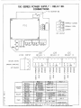
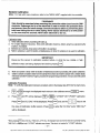
100 SERIES POWER SUPPLY / RELAY BD.
CONNECTIONS
JP?
I
I
TO MOTHER SO
1
~~
\(]]I
I
JP5
Kl
'"'~D
PSl
NO
'"
IN
...,
(\ 01
(\ 01
(\ OJ
>->
f\)
00
w
NORMALLY
CLOSED
NORMALLY OPEN
COMMON
DRY CONTACT
\~,
F8
""'0_,OJ
m'
I
I
\"
vJ7
Ta R
fW 1
G
F
fUSES,
SR.2sev
8
~
J2A
8
~
S-
W
III
""
..
L] NE I NPUT
Fl
10
l(LA'll
J
LINE
INPUT
RELAY
J2C
J28
J2A
RELAY
1
RELAY 3
2
J7
RETURN (WHITE)
. GROUND (GRN/YEL)
HOT (BLACK)
B
B
NC
NO
z
o
z
;:0
o
;0
:s:::
:s:::
G
\oJ
C)
;:0
o
rh
o
c
z
o
o
:s:::
:s:::
I
o
I
N
r--
TIMER
z
:s:::
~
~
o
o
o
Z
o
(f)
RELAY 1
SLOWDOWN
MCT110
SLOWDOWN
MCT110C
pH CONTROL
MCT120
pH CONTROL
MCT120C
ORP CONTROL
MCT130
ORP CONTROL
MCT130C
OPTION "0
SLOWDOWN
MBC110
. M8C110C
SLOWDOWN
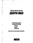
BLOWDOWN
M8C110D
LOCKOUT
MPT110
LOCKOUT
MPT120
TIMER OUT 1
MPT150
TIMER OUT 1
MPT150H
OPTION LJ
H
NOTE: WHEN RELAY # 1 IS ON
http://www.novatech-usa.com/Products/Process-Control-Instrumentation
o
C)
o
o
:s:::
c
z
i=
~
-<
r
"1J
1"'1
rh
»
»
r
o
z
r'1
G
\oJ
:::0
:::0
;:0
0
0
s:
s:
B
B
NC
NO
z
z
o
o
:s:::
s:
»
;:0
»
o
z
o
"1J
rTJ
Z
;:0
r
r
~
~
o
r
o
(f)
o
r'1
G
rh
C)
;:0
0
c
z
0
"1J
rTJ
Z
o
o
o
o
NO
z
o
»
r
r'1
(0
NC
»
(f)
BOilER
B
r
5
COOUNG
TOWER
8
RELAY 3
RELAY 2
INHIBITOR
TIMER OUT 1
TIMER OUT 1
TIMER OUT 1
ALARM RELAY
**
**
**
28
8l0WDOWN
SLOWDOWN
SLOWDOWN
BIO A
810 A
I TIMER OUT 1
I ALARM RELAY
I
SIO
B
DAY TIMER
RELAY #2
ALARM RELAY
IS OFF Af\IO VICE VERSA
Tel: (281) 359-8538 Toll Free:(866) 433-6682
W
o
o
s:
s:
o
z
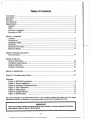
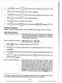
Table of Contents
Introduction
Description
Warranty
FCC Warning
Specifications
General
3
4
4
4
'.'
5
5
5
6
6
ORP
Summary of Keypad
Summary of LED
Section 1Installation
Location
Accessories
Installation Notes
Mounting
Electrode Information
Electrical Wiring
7
7
7
8
8
11
Section 2 Genera/Instructions
Menu Structure
15
Section 3 Start-.Up
General Information
Configure Analog Inputs
System Calibration
Program Parameters
16
16
17
18
~
Section 4 Maintenance
20
Section 5 Troubleshooting Guide
21
Drawings
Figure
Figure
Figure
Figure
Figure
Figure
Figure
1, MCT130 Front Panel
2, Typical Installation
3, Enclosure Dimensional Data
4, TON-1 Electrode
5, Relay Board
6, Daughter Board
7, Mother Board
3.
7
9
10
~
12
13
14
This manual describes the standard model MeT130. If your controller is supplied with options refer to the pages
following this manual for a description of each optional feature and its effect on operating procedures.
IMPORTANT
Before proceeding, read the red c:ard in the front ofthe controller.
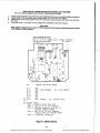
about start-up. Refer to Figure 7, Mother Board.
http://www.novatech-usa.com/Products/Process-Control-Instrumentation
It contains important information
Tel: (281) 359-8538 Toll Free:(866) 433-6682
Introduction
The PULSAtrol™ series of microprocessor based controllers have been designed
capability to control and monitor a wide range of parameters, both analog and digital.
with the
This instruction manual is based on the model number of your controller and covers those
functions found on your controller. For your convenience, there is an abbreviated instruction and
software "MENU MAP" laminated card supplied with all manuals to be kept with the controller. This
card is not a substitute for this instruction manual. It is supplied as a quick reference only and
should be used in conjunction with the instruction manual.
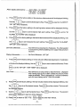
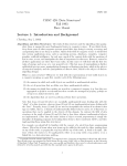
Take a moment to review Figure 1, MCT130 front panel and become familiar with the PULSAtrol™
Series 100 controller.
(CPT"" E)
MOufr.'tD i'LOW'\
\
\
( PIoN£\.
SCREWS
)
Z PLACES
\Yfy-JlHryW
I
•
I
o
I
o
I
.j
,
I
[ RfLAT
INDIC\ToRS
)
J Pl,ACOS
{ HQ> SWlTC>iES )
J PUCES
Figure
1, MCT130 Front Panel
-3~
http://www.novatech-usa.com/Products/Process-Control-Instrumentation
Tel: (281) 359-8538 Toll Free:(866) 433-6682
I
I
j
Description
The MCT130 is designed to monitor and cdntrol ORP with a control set point in millivolts (mY)
entered into the MCT130through the keypad. The set point has a built-in limit timer that acts as
a fail-safe to prevent system overfeed.
The design also inclUdes a high/low alarm indicator available with optional relay output and/or dry
contacts. The alarms can be.operated in one of two modes: follow set point, in which an alarm offset
is entered and the alarms automatically adjust themselves around the set point or independently
set, which allows you to independently set both the high and low alarms.
Hand/Off/Auto keys are provided on the keypad for immediate control of pumps, solenoid valves,
etc .• without scrolling through menus. The design allows the MCT1 $0 to accept options such as
Analog Output and/or Mounted Flow Assembly with Flow Switch. All inputs are fu lIy isolated.
effectively eliminating ground loops and other interference found in the industrial environment.
How to Use this Manual
For easy reference, the functions on the PULSAtrol™ controller discussed
illustrated as follows:
o
in this manual are
= The keys on the keypad which you are required to push for the function described.
11.::::1 I. = The
I
main menu displayed for the function described.
Warranty
Pulsafeeder, Inc. warrants PULSAtrol™ control systems of its manufacture to be free of defects
in material or workmanship. Liability under this policy extends for24 months from date of shipment.
The manufacturer's liability is limited to repair orreplacement of any failed equipment or part which
is proven defective in material or workmanship upon manufacturer's examination. This warranty
does not include removal or installation costs and in no event shall the manufacturer's liability
exceed the selling price of such equipment or part.
II
I
I
The manufacturer disclaims all liability for damage to its products through improper installation,
maintenance.
use or attempts to operate such products beyond their functional capacity,
intentionally or otherwise, or any unauthorized repair. The manufacturer is not responsible for
consequential or other damages, injuries or expense incurred through the use of its products:
The above warranty is in lieu of any other warranty, whether expressed or implied.
The
manufacturer makes no warranty of fitness or merchantability. No agent of ours is authorized to
provide any warranty other than the above.
FCC Warning
This equipment generates and uses radio frequency energy and if not installed and used properly,
that is, in strict accordance with the manufacturer's instructions. may cause interference to radio
communications.
It has been type tested and found to comply with the limits for a class A
computing device pursuant to subpart J of part 15 of FCC Rules. which are designed to provide
reasonable protection against such interference when operated in a commercial or industrial
environment.
Operation of this eqUipment in a residential area is likely to cause interference in
which case the user, at his own expense, will be required to take whatever measures necessary
to correct the interference.
-4http://www.novatech-usa.com/Products/Process-Control-Instrumentation
Tel: (281) 359-8538 Toll Free:(866) 433-6682
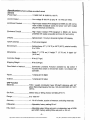
Specifications
General
(Factory settings are default values)
Power Input
1101220 VAC @ 50/60 Hz 100 VA.
Control Output
Line voltage @ 600 VA (5 amp @ 115 VAC) per relay.
Enclosure Prewired
High impact resistant PVC designed to NEMA 4X, with convenient molded receptacle cords and power cord with molded
plug for electrical connections.
Enclosure Conduit
High impact resistant PVC designed to NEMA 4X, factory
predrilled with easily accessible terminals for hard wiring.
Display
Alphanumeric 1 line by 8 character lighted LCD display.
HIOI A Switches
Front panel keypad.
Environment
Ambienttemp. OaF (-17.8°C) to 122'F (50°C); relative humidity
Oto 100%.
Dimensions
Width 7~ (17.78 cm) X height 7" (17.78 cm) X depth 6.5"
(16.51cm).
Controller Weight
6 Ibs (2.7 kgs)
Shipping Weight
8 Ibs (3.6 kgs)
Flow Switch or Interlock
Connection provided. Function activated by dip switch if
mounted flow switch or remote flow switch not ordered with
controller.
Inputs
1 analog and 2 digital
Outputs
1 analog and 2 relays
........
1I
ORP Function
Electrode
TON-1 sealed combination type; KCI-AgCI reference with 3/4
glass filled polypropylene flow tee. 125 psi (8.65 BAR) @ 125°F
(52·C).
A
I
I
I
I
i
Set Point..
Select rising or falling; factory set falling 870 mY.
Range
0 to 1000 mV
Accuracy
+/- 1% of full scale. at point of measure, excluding electrode.
Differential
HilLo Alarm
:
!
i
Adjustable; factory setting 20 mV.
Adjustable select follow set point or independent set of HIGH
and LOW. Factory setting follow set point +1- 25 mV.
http://www.novatech-usa.com/Products/Process-Control-Instrumentation
1
Tel: (281) 359-8538 Toll Free:(866) 433-6682
Lim it Timer
Adjustable in one (1) minute increments up to 24 hours, factory
set at 1:30 hr/min.
Surnmary Of Keypad
Home
When pushed, returns displayed menu back one level in the
menu structure.
Enter
When pushed, enters displayed variable or value.
Scroll
Up
Used to scroll up through (view) menu structure.
Scroll Down
Used to scroll down through (view) menu structure.
Arrow
Used to move between variables and to increase or decrease
numerical settings.
Keys
Relay Keys
Summary Of LED Indicator
Power Indicator
Hand/Off/Auto (HOA) switches. Pressing
ONCE forces corresponding output relay
LED color amber.
TWICE forces corresponding output relay
color red.
THREE times retums control to automatic;
point, green if out of set point.
key:
on for five minutes;
off indefinitely; LED
LED off if within set
Lights
Illuminates when power is supplied to unit.
Flow Indicator
Illuminates when flow is present through flow switch. This
indicator will not be functional or labeled if mounted flow
assembly was not ordered. User can activate function on site.
Green - Indicates flow
Alarm Indicator
Flashes red when an alarm condition is present.
Relay Indicators
AMBER if forced on.
RED if forced off.
OFF if in auto mode and cootrol function is not automatically
activated.
GREEN if activated automatically,
-6http://www.novatech-usa.com/Products/Process-Control-Instrumentation
Tel: (281) 359-8538 Toll Free:(866) 433-6682
Section 1 -Installation
Location
Select a mounting location convenient to grounded electrical and plumbing connections. Mount
the controller on a wall with adequate lighting, at a convenient level and accessible for
adjustments. Avoid locations where the controllerwould be subjected to extreme cold or heat [less
·than O'F (-17.8'C) or greater than 122 F (50'C)], direct sunlight, vibration, vapors. liquid spills or
EM I (electromagnetic interterence; i.e., strong radio transm ission). Installation shou Id com ply with
all national, state and local codes.
D
NO~5:
NOi
AU.
eOulPME
....
..,. SHOWN
IS
PRCVlOEC
~":'M
(;:'Ut...$AlI'ol""
Cont"oller')
"'I'o:C IS
~RM
r
· 1r
~LOAT
COO:'ING TOWER
---+
'--
swr;c ...-;::=
W,t.7ER
~
.~
t
RC:F;:Re:NC~
ON;".':".
OUTP:.;: OPTION-0- \
\
d
C11"Y
rop.
~
I
j
~
OO"'TIQS-S'\.
II
MOUN7[;:;
I
vf~
T
.-....A
~
I!
I rT~K1
,U
I ,I
I !
I
I
i~i
1
I
I I
(CHEMZCAl.
pu~p)
i
CIRCUlJo,"TION
F~u"p
-;
L
·
II
=j l../
Figure 2, Typical Installation
Accessories
(Available
1.
2.
3.
4.
through your PU/stlfeeder distributor
or sales representative,
but not included as standard)
Two manual gate valves, one on each side of the electrode or flow assembly if controller
incorporates a flow sWitch, to isolate the electrode or flow assembly for installation and
routine maintenance.
One Y -strainer before flow assembly.
Chemical metering pumps as required.
External alarm, if controller incorporates alarm relay.
Ref~r to Figure 2, Typical Installation.
Installation Notes
1. Install sensors or sample stream flow assembly at some point before chem ical injection points,
where chemical and water are thoroughly mixed. Refer to Figure 2, Typical Installation.
2. Measuring surtaces of the sensor electrodes must be continuously immersed in system water.
3. Inlet pressure of the sample flow assembly must be higher than the outlet pressure so water
will flow past the sensors. Flow rate must be at least 1 GPM.
4. Install strainer on the upstream side of the flow assembly.
5. Install hand valves on each side of the flow assembly for easy isolation and removal of sensors
and strainer screens.
-7http://www.novatech-usa.com/Products/Process-Control-Instrumentation
Tel: (281) 359-8538 Toll Free:(866) 433-6682
6.
Direction of flow should be from the bottom to the top of the flow assembly.
Refer to Figure 2, Typical Installation.
llWARNINGH
1'hestandard flow assembly, if provided with this controller, is constructed of durable glass
.filled polypropylene (GF~PL).
.
11
Standard connection to flow line is 3/4 NPl, but we haveprovideda PVCthreadto slip adapter
so that a PVCweld joint, if preferred, can be made.
If N,PT connections are used, hand tighten until snug, then tighten an addition~1half turn.
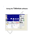
Mounting
Mount controller on a wall or other vertical surface. Position so operator has access to the unit
and a clear view of front panel display. Refer to Figure 3, Standard Enclosure Dimensional Data
and Mounting Hole Template for mounting details of our standard enclosures. An actual size
Mounting Template (Attachment A) is provided for your convenience.
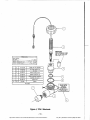
Electrode Information
!!WARNING!!
Care snould be exercised when removing the protective rubber boot from the OAP
electrode. Submerge the tip of the electrode in water to loosen the protective boot
and remove. Save for future storage. Care should also be taken to prevent the glass
bulb from hitting the tee or other piping. Never expose electrode to air with power
on for more than 45 seconds. Never allow electrode to dry out.
To remove electrode from its tee for cleaning and for reinstallation, keep the following in mind:
1.
Remove power from the system.
2.
Remove pressure from the system priorto unscrewing the electrode. To remove pressure,
close hand valves located before and after flow assembly.
3.
Open the sample port. This will facilitate removal of electrode.
4.
Unscrew the coupling nut.
5.
Remove electrode. If necessary, assure slot on nut and dimples on electrode or electrode
holder are NOT lined up.
6.
Reinsert electrode; conductivity electrodes are keyed.
7.
Hand tighten nut.
8.
Close sample port.
9.
Reapply pressure and flow by opening hand valves slowly to avoid water hammer.
10.
Reapply power to the system.
11.
You should calibrate sensor at this time.
1
I
I
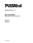
Refer to Figure 4, TON·1 Electrode, and Section 4, Maintenance for specific information and
specification for electrodes supplied with your system.
,I
I
1
I
I
I
i
·8http://www.novatech-usa.com/Products/Process-Control-Instrumentation
Tel: (281) 359-8538 Toll Free:(866) 433-6682
/
7.00 SO.
177.Bomm
6.00 SO.
152.4Omm
iI~
I..
• i
• :
"I
5.75 SQ.
146.05mm
I
o
o
I
I
5.~
1.39.iOmm
6.19
lS7.23mr':'l
287.02mm
11.3
I
"
I
=
I
t
I..
I
l
I
I
j
j
Figure 3, Enclosure Dimensional Data
-9http://www.novatech-usa.com/Products/Process-Control-Instrumentation
Tel: (281) 359-8538 Toll Free:(866) 433-6682
~
-----'i
M'ORTANT
2
REMOVE PROltCTNE
RUBBER
:;~1
BOO. FOP. OPERATION.
KEEP
B007 IN SAr~ PI.ACE FOR
SP:::CI~::A'iIONS:
_G,,:
SINGL£
OR"
/_
JUNCTION
R~SPONS~
no.c":
_TION
T£"PERATUR~
IlANG~,
OPEFlJITINC P~SSUR<:
s
I
c
2DOOm"
SE;C(9~:: RESPONSE)
-5 TO .. sO' C /100 PSI
20
RANC~.;
50
:ao-110-0.2
PSI/
0
CAlJIION
TAG.
2S'
~
............
C
PvC
'-OAFT!RS
:!>i"- o.lAlE AOA"liP..
03-0SJ-00
~
PvC
FLOW
6
03-056-56
..
5
03-oos-()4
GASKET.
O-RING
~2-02S
03-005-Q2
CASKET.
O-RINC
~2-1l9
:;
03-096-6'
2
04-0<5-<l1
HOUlOP..
06-008-00
... I ....., I
"""
EI.!::C1ROOo
£LE:CTROOE.
.......
-
PULSATllOL
OR?
ON-I
-
COUPUNC
.....
o-0
NUT
PvC
suP .oD.IPT£RS
PROVlO£O FOR \'1lUR
CONVENrE.NCE
CAUTION
Figure 4, TON·1 Electrode
- 10·
http://www.novatech-usa.com/Products/Process-Control-Instrumentation
Tel: (281) 359-8538 Toll Free:(866) 433-6682
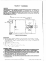
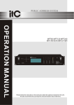
e:lectrical Wiring
Tile PUlSAtro!TM Series 100 electronic circuitry is protected by a (Bussman BKlPCE-1) 1 amp tuse
(F4). Each output relay is individually protected by replaceable (Bussman Sk!PCE-5) plug-in 5
Amp fuses (F1 , F2 & F3) located on the power supply/relay board. Reterto Figure 5, Power Supply/
Relay Board.
!!CAUTION!!
Line voltage is present on the relay/power supply board located in the bottom of
enclosure, even when power is off.
'-
POWER MUST BE DISCONNECTED
WHILE CONNECTIONS
ARE BEING MADE!
Note: For proper rejection of AC line voltage spikes, sensor EMI noise rejection and
personal safety, the case ground (SAFETY GROUND) must be properly installed. If
there is ANY doubt, consult a.qualified electrician.
Prewired units are supplied with 1o foot, 18 AWG 3 wire grounded power cords and clearly marked
18 AWG 3 wire grounded receptacle cords for all controlled line voltage outputs.
Conduit units are factory predrilled with easily accessible terminals for hard wiring. See Figure 5,
Power Supply/Relay Board, for input and output power connections. Use only 16 or 18 AWG wire
for conduit power and load connections. Never run power and signal wiring (sensor, proportional
or recorder outputs) together in the same conduit.
When connections
Note:
are required by user, follow the instructions below:
Liquid tight fittings are provided for all signal leads.
Open Enclosure
•
Remove the screws from upper control panel and lower control panel.
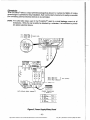
Flow Switch or Interlock
It is recommen ded that a flow switch or auxiliary dry contactfrom the control panel be used to make
outputs inoperative when the circulating pump is shut down. This connection is provided for on all
units with or without mounted flow assembly. If a flow switch is not ordered with the unit, this
function will be inoperative. To use the interlock feature, connect a flow switch or auxiliary dry
contact from another device. Refer to Figure 6, Daughter Board, for flow switch or interlock
connection marked JP1 pin 7 and 8. To activate function, turn switch S1-"2" (located on the Mother
Board, Figure 7) on. Tum power off, wait 15 seconds and turn power back on.
Sensor Connections
Units supplied with GFPPL flow assemblies (option B) come from the factory with all sensors preconnected. Refer to Figure 6, Daughter Board, for location of sensor connections.
Alarm Dry Contact
Alarm dry contacts (Rated @ 500 rnA) are provided when Option K has been ordered for user
connection. Refer to Figure 5, Power SupplylRelay Board.
- 11http://www.novatech-usa.com/Products/Process-Control-Instrumentation
Tel: (281) 359-8538 Toll Free:(866) 433-6682
Beceptacles
The PULSAtrofTMoffers a unique prewired package that allows it to maintain its NEMA 4X rating
even though it is prewired for easy installation. Each cord is clearly marked and readily accessible
tor connecting external electrical devices to be controlled.
Note:
The solid state relays used in the PULSAtrofTM result in a small leakage current at all
receptacles. While this can possibly be detected by a voltmeter, it is insufficient to power
any typical electrical device.
';7 - 1 WH!TE WIRE
~7-2
GREEN WIRE
BLACK WIRE
}
POWER CORD
~7-3
I
j
JP5-'
JP5-2
JP5-3
~
FUSE.
RELAY N.O.
RELAY N.C.
RELAY COMMON
~
DRY CONTACT
F'1-3
CONDUIT CONNECTIONS
( OPTION A )
A
HOT
J2
J5
NEUTRAL
RELAY'
8
J3
J4
HOT
NEUTRAL
RELAY 2
C
Jl
J6
HOT
NEUTRAL
RELAY .3
Figure 5, Power Supply/Relay Board
- 12http://www.novatech-usa.com/Products/Process-Control-Instrumentation
Tel: (281) 359-8538 Toll Free:(866) 433-6682
r-I
.
'3
,~
- -- --_.
['51- t'''-I_.,jCU;1
e:s
C2:2:
C:2
100
i
;U
W
(JI
ill ill ill
Wtll til
-.I GJ W
Ui5
0,
JPl
-
I
c:::J CJ CJICJIL......JICJ
00
7
J?
JP1-7
JP1-8
JP1 9
JPI-10
JP 1-1 1
JPl-12
ORP
I
°1°1°1° W~2 @)II
8 9.10j1112
I
IN
DINO
DING
DIN 1
FLOW
SWITCH
WATER
DIN1
AOUT+
A.NALOG
AGND-
METER
OUT
- I
Figure 6, Daughter Board
-13http://www.novatech-usa.com/Products/Process-Control-Instrumentation
Tel: (281) 359-8538 Toll Free:(866) 433-6682
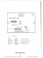
READ THE FOLLOWING BEFORE PROCEEDING
ANY FURTHER!!
This unit requires initialization upon start-up. Directions are as follows:
1,
2.
3.
4.
Before power is supplied, remove the two screws holdingthe front cover closed with a phillips screwdriver,
Locate switch 81 on the mother board. Assure switch 51- "S"is in the "on" position.
With the front cover closed, power unit up for 15 seconds. Remove power, open front cover and tum
81·"8" off.
Close front cover. Turn power on and configure the controller per the user's manual.
CAUTION!!
.
When power is supplied to the unit, 115 VAC is present on the power supplyfrelay board located
in the bottom of the enclosure.
9L9£-v£Zl,
DOC 0 0 DO Dt
NC
D!SPLAY CONTRAST
SID:: ADJUST
\:
(
I
I
+
U
0
1
Dc" Dc'.
OC2J
OC,g
Oe2Q
Dc's
JP4
$1-1
51-2
51-3
51-4
51-5
$1 -6
51-7
051-8
o
[]
0<:2'
r:r-r-r-J:lJ~
l:!:W:l:l
HEADER FOR OPTION BOARD
OFF
OFFOFF
OFF
OFF
OFF
FLOW DISABLED
ON-
FLOW ENABLED
OFF
OFF -
OPERATE
ON-
FACTORY R~INIT
FACTORY REINIT:
5TE? 1 - REMOVE POWER FROM UNIT
STEP 2- SET S 1-" 8" TO ..ON" POSITION
STEP 3- RESTORE POWER TO UNIT FOR 15
SECONDS; REMOVE POWER
STEP 4- SET 51-"8". TO "OFr:" POSITION,
CLOSE COVER AND RESTORE POWER
STEP 5- CONFIGURE CONTROLLER
Figure 7, Mother Board
- 14http://www.novatech-usa.com/Products/Process-Control-Instrumentation
Tel: (281) 359-8538 Toll Free:(866) 433-6682
Section 2 - General Instructions
Menu Structure
The PULSAtrol™ menu structure, as well as the hardware, were designed with the user in mind.
The menu structure diagram supplied with the controller was generated to reflect a PULSAtrol™
rnodel MCT130. The laminated "MENU MAP" supplied with your controller reflects your system
with options.
Display Data
All PULSAtrols™ have a display data menu. This menu displays system parameters only and no settings or adjustments
are made through this menu.
Calibrate Sensor
All PULSAtrols™ with analog input, such as conductivity, have
this menu. In this menu, the user is prompted to choose either
2 or 3 point calibration. After a choice is made, the user is
prompted to enter value of La, MID (if 3 point is chosen) and
HI calibration solution.
Set Points and Alarms
All PULSAtrols™ with analog input, such as conductivity, pH or
ORP, have this menu. In this menu, the user is prompted to
enter all settings pertaining to alarms and set points.
System Configure
AI! PULSAtrols™ have a system cont;gure menu. In this menu,
the user is prompted to configure system functions to the
specific application. System Configure can include such things
as time of day, date, rising or falling set point, follow set point
or independent set of high/low alarm and the selection of the
inhibitor feed mode.
!
i
1j
I
Note: After five minutes of no keypad activity, the controller will display system ORP.
I
]
I
~15http://www.novatech-usa.com/Products/Process-Control-Instrumentation
Tel: (281) 359-8538 Toll Free:(866) 433-6682
Section 3 - Start-Up
GEneral Information
Before applying power, insure that devices being controlled are not in a position to cause harm
or damage if activated upon initial start.up.
Wi1h the controller now installed in a convenient location, supply powerto the controller. The power
LED indicator light will be illuminated. When the controller is powered up, it will display II
SYSDATA
II.
The PULSAtrol™ is a flexible yet powerful controller. The default values for all uControlufeatures
. have been factory set, but you will want to fine tune the controller to meet your specific application.
COf1tinueby configuring the controller functions.
{=I Isc~~1II
or
to
CONRGUfl
II, press [ENTER
I.
Configure Analog Input
No1e: For help with menu locations, refer to the "MENU MAP" supplied with your controller.
1. Proceed by configuring controller as prompted, "HI/LO AL". pressl
keys to choose alarm configuration: 'TRAKSEr',
EmER
I
and use the
1~1[=1
tracking set point, or "INDEPEND".
independent set of high and low alarms, press IENTEfI). "SET pr' will be displayed.
2. Press
I 1 1=1
and
ENTER
to display the desired set point configuration: aRISING" or nFALL! NG".
Press I ENTER 1 to enter your selection, "YERSIONn will be displayed.
3. Press I ENTER l to display the software version. Press I EN'TCFl1 again and IISENSITIY" will be
displayed.
4. Press
I I
ENTER
and II1" or the last setting entered will be displayed, 1 being the most sensitive and
20 being the least. The setting determines the number of samples that are averaged together
and the number of seconds before a new reading is displayed. This reduces the typical'
fluctuation of digital displays. Use the
[EtfiCR
I
ITJ[l]
keys to set the desired sensitivity and press
to enter your sensitivity setting. If no options are present, "HI/LO AL" will be displayed.
5. If other options are present, continue with step 5. If no options are present, skip step 5 and
continue with step 6. Refer to the option instructions supplied with your owner1smanual and
configure options as instructed.
6. Press
I I
HOME
again and II
CONRGIJR·
II is diSPlayed·!=1
or ISC:LLJ to access II
SYSCAI.
II.
- 16http://www.novatech-usa.com/Products/Process-Control-Instrumentation
Tel: (281) 359-8538 Toll Free:(866) 433-6682
I
..
System Calibration
Note:
For help with menu locations, refer to the "MENU MAP" supplied with the controller.
!!WARNING!!
Care shoUld be exercised when removing the protective rubber boot from the ORP
electrode. SUbmerge the tip of the electrode in water to loosen the protective boot
and remove. Save for future storage. Care should also be taken to prevent the glass
bulb from hitting the tee or other piping. Never expose electrode to air with power
on for more than 45 seconds. Never allow electrode to dry out.
Calibration Notes
1. Verify calibration before proceeding with start up.
2. For a higher degree of accuracy, three point calibration should be utilized using three standard buffer
solutions, if available.
3. Between each sample, rinse sensor with buffer to be sampled.
4. Refer to solutions A and B in Section 4, Maintenance, for other mV solutions to be used for calibration.
IMPORTANT
Always put the sensor in calibration solution before, or while the low, middle, or high
calibration steps are being displayed and before pressing
5.
6.
I
ENTER
I.
Make sure probe is clean (refer to Section 4, Maintenance) before proceeding with system calibration.
Obtain a sample of system water from the sample flow stream and test the sample with a reliable tester.
Ifthe tester and the PULSAtrol'" agree, proceed with programming parameters. If not proceedwith system
calibration.
Calibration Procedure
Note: To verify that calibration has been accepted, refer to the display data (SYS DATA) main menu.
1.
2.
Isc~~l I%~j
I I,
I
or
Press
ENTER
through the displayed main menus to the calibrate sensor II
2/3 PT will be disPlayed·l~ou.l
or
1~~1
I
II menu.
to "2 POINT' OR "3 POINT" calibration.
Press [EtlTER and' "La CAL" will be displayed. Press ENTBlj1 and use the
the value of calibration
SYS CAl.
IT][JJ keys to set
buffer solution. Press [ENW11 to enter the uLD CAL n point. "MID CAL"2
will be displayed.
When preSSinglEKICRIfrom "LO CAL", "MID CAL", or "HI CAL", the displayed value is what the electrode is presently reading.
2"MID CAL" is displayed only if "3 POINT" calibration was chosen. This step is not required for "2 POINT" calibration.
- 17 http://www.novatech-usa.com/Products/Process-Control-Instrumentation
Tel: (281) 359-8538 Toll Free:(866) 433-6682
I
I
3.
~'.
Press{ ENTER r and use the!JJ
[[]
keys to set the value of calibration buffer solution. Press
I 1to enter the uMID CAL n point. nHI CALli will be displayed.
Press[ENTER l and use the IT][[] keys to set the value of calibration buffer solution. Press
ENTER
4.
(EHTElIj to enter the UHI CAL n point. ala CALli will be displayed.
I l
5.
Press
6.
Press HOME ] againand the I:
HOME
to return to "2 POINT" OR "3 POINT'.
I
SYSCAl.
IlmainmenuisdiSPlayed.I~~lorISC~~l.LltoacceSs"SETPTS".
Program Parameters
Note: For help with menu locations, refer to the "MENU MAP" supplied with your controller.
Set Points & Alarms
Rising or Falling Set Points
Every analog input has a set point (trip point), the setting at
which the controller activates an output, such as a solenoid
valve when conductivity set point is exceeded or an acid pump
if ORP exceeds a desired limit.
Set point display abbreviations ... ORP Rising Set Point - uORPRSP"
ORP Falling Set Point - uORPFSpu
1.
!sc~~l [=1
2.
Press
or
I
EN'TCR
through the displayed main menus to "SET PTS".
I· One of the above abbreviations will be displayed depending
on the set"point
configu ration.
3.
I
Press [ ENTER and the factory setting or the last set point entered will be displayed blinking. Use
the
OJ [JJ
keys to set the desired set point. Press
IENmlj
to enter the set point value. a AL
OFFS"P1 will be displayed.
High or Low Alarm Settings ........ Every analog input has a high/lowalarm. The alarms can be
configured one of two ways. The controller is factory configured to track the set point '7RAK SEr'. An alarm offset is
entered that sets the alarm point above and below the set point
of the controller. Example: With an uAL OFFSr of 20, if the
set point is 800 the high alarm would be at 820 and the low
alarm at 780. The high/lowalarms can also be configured with
independent set points for the UHf ALARM" and the uLO
ALARM", This is accomplished through the ij CONFIGUR II menu.
'"AL OFFSET" is displayed only if "HI/LO AL".is configured to track the set point. If so, skip steps 5 and 6. If HIILO
AL" is configured for independent setting of highllow alann, skip step 4 and proceed with step 5.
- 18http://www.novatech-usa.com/Products/Process-Control-Instrumentation
Tel: (281) 359-8538 Toll Free:(866) 433-6682
Alarm display abbreviations:
4.
....... Alarm Offset - "AL OFFST'
High Alarm - uHI ALARM"
Low Alarm - uLO ALARM"
I I
Press
and the factory setting or the last alarm offset entered will be displayed blinking.
ENTER
Use the
[!]Q]
keys to set the desired alarm offset. Press
I I
ENTER
to enter the nAL OFFST".
"SPT DIF" will be displayed.
I
5. Press ENTSl] and the factory setting or the last high alarm entered will be displayed blinking.
Use the
[!]Q]
keys to set the desired high alarm setting. Press I!;N'TCR 1 to set the "HI
ALARMII. "LO ALARM" will be displayed.
6.
l I
Press
and the factory setting orthe last low alarm entered will be displayed blinking. Use
ENTER
[!]Q]
the
I I
keys to set the desired low alarm setting. Press
ENTER
to set the "LO ALARM".
nSPT DIF" will be displayed.
Set Point Differential
Also referred to as dead band or Hysteresis. The offset applied
to a set point to prevent chattering of an output relay around a
set point.
Display Abbreviation
Set Point Differential - SPT OfF
7.
I
ENTCFl] and the factory setting or the last set point differential (dead band or hysteresis)
Press
entered will be displayed blinking. Use theOJOJkeys
I I
ENlEFt
to set the nSPT DIF". ·ORP TIMER" will be displayed.
Limit Timer
8.
to setthe desired differential. Press
Also referred to as lockout timer or feed limit timer. Displayed
only if analog input is pH or ORP. It limits the amount of time
output is activated. Timer is adjustable in 1minute increments
up to 24 hours; factory set for 1 hour 30 minutes.
Press [!;mER I and the factory setting or the last minutes entered will be displayed blinking. Use
the
[I]Q]
keys to set the desired minutes. Press
I I
erTCR
to set the m i~utes. The hours will
be displayed blinking.
9.
Use the
[!]Q]
abbreviation
10. Press [HOME
k~ys to set the desired hours. Press
I I
ENTER
to set the hours. The set point
displayed in step two will be displayed.
I
to return to "SET
PTSlJ·I~OLLIor 1=1for oth.er main menus.
http://www.novatech-usa.com/Products/Process-Control-Instrumentation
Tel: (281) 359-8538 Toll Free:(866) 433-6682
.............. _
-.~~~
~_.~~
,.~
- ..---
-.- .._.--_ •.---
'
_--.~,
..~,..~, •.•... ".,.,
-- .•.-.- ..-..--
------.-- ..-.•.-
_............
.,
_··_·__ ·~~.·'''''ff
..N.~'~ ..·,~W"."·.,~
~.. ,,.,.. ,•.~_
,_,,_,__,_._.. __.. _._..•_
_•.•'•.••.•'•.••.• '•• '.,,_
_
.. _...• _
_ ..•. _ .•~,._.
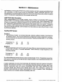
Section 4 - Maintenance
Melintenance on the PULSAtrol™ MCT130 controller requires only thatthe operator periodically cle-an
the electrode(s). All other service should be pertorrned by factory authorized personnel only.
MCJdifi cationsto 0 rtampering with the ci rcuit level components makes all warranties, written or implied,
and/or manufacturer's responsibility for this controller null and void.
OR P Electrode Information
OFlP standard buffers are not readily available, making it difficult to standardize ORP.systems
against buffers. The following solutions (A and B) can be easily mixed. Like pH electrodes, ORP
sensors are subjected to coating and abrasion by the measured liquid and, in certain instances,
are "poisoned" by chemicals which may be present if the system goes but of control. To improve
the reliability of ORP measurement and control, the following is a means of testing electrodes in
sol utions of standard potential, which will determine if electrodes are responding correctly or need
rna intenance attention.
Testing ORP Sensor
Solution A
•
Use sufficient pH buffer 7 to immerse electrodes. Dissolve sufficient crystals of quinhydrone
to saturate solution. This may be evidenced by undissolved crystals suspended in solution.
immerse electrode into liquid and measure potential. Potential wouldbe within +/- 10m Vof the
following values:
Temperature ·C
Potential, mV
20
+92
25
+86
30
+79
Solution B
• Remove electrodes and rinse thoroughly with water. Make up a second saturated qUirihydrone
solution with pH buffer 4. Immerse electrodes. There should be a rapid response to the
following potential:
Temperature 'C
Potential, mV
20
268
25
+263
30
+258
The millivolt difference between the two solutions is theoretically 177 mV. The absolute values may
shift upward or downward a few millivolts due to slight variations from theoretical potential by the
reference electrode.
If system potentials are correct, flush electrodes with deionized water and measure the liquid in
question. If incorrect by more than 10 mV, electrodes should be cleaned with aqua regia (three
volumes hydrochloric acid, one volume concentrated nitric acid. Note: Solutions are very
corrosive! Handle with extreme care). Repeat above tests. Once satisfactory readings are
obtained, install electrode and make measurements of liquid in question. Note: Quinhydrone
buffer solutions are not stable; discard immediately after use.
-20·'
http://www.novatech-usa.com/Products/Process-Control-Instrumentation
Tel: (281) 359-8538 Toll Free:(866) 433-6682
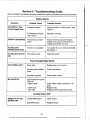
Section 5 - Troubleshooting Guide
/fyour controller is not operating properly, proceed through the troubleshooting
instructions below.
Mother Board
Symptom
~O DISPLAY (See
Power Supply first)
Probable Cause
Possible Solution
Impropercontrast
Adjust contrast on mother board.
Figure 7.
Environment exceeds
122"F (50·C)
Relocate controller.
ERRATIC READINGS
Improperly grounded
power
Assure power and ground integrity.
Shields of all sensors should be connected at controller end only.
FLOW LIGHT
NEVER ACTIVATES
Function not activated
Turn switch S1-2 on mother board ON.
See Figure 7.
FLOW LIGHT STAYS
Flow switch stuck
Clean flow switch.
See
ON
Power Supply/Relay Board
NO POWER LIGHT
Blown fuse
Interconnecting
loose
Replace fuse on the board.
cables
No power supplied
NO OUTPUTS
If the output front panel
LED is lit:
• ribbon cable
• blown fuse
• bad relay
Check connections.
Check power source.
Check ribbon cable connection or replace.
Replace fuse.
Replace power supply/relay board.
Cooling Tower ORP
INABILITY TO CALIBRATEORP
Fouled ORP sensor
Clean sensor.
Bad ORP sensor
Replace sensor.
- 21 http://www.novatech-usa.com/Products/Process-Control-Instrumentation
Tel: (281) 359-8538 Toll Free:(866) 433-6682
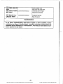
ORP FEED LED OFF
AND:
ORP ABOVE RISING
SET POINT
ORP BELOW FALLING SET POINT
·Solve problem and
limit timer will reset itself:
Chemical drum empty.
Sample line blocked.
Limit timer timed out
Limit timer timed out
Fouled pH sensor.
Bad pH sensor.
Reinitialization
If the above troubleshooting
steps fail to explain or solve condition, factory
reinitialize (see Figure 5, Mother Board), If condition still exists, contact factory for
customer service assistance at 1-800-333-66n. A RA (Return Authorization) number is required for any return.
- 22http://www.novatech-usa.com/Products/Process-Control-Instrumentation
Tel: (281) 359-8538 Toll Free:(866) 433-6682