1
Automation and control
Human/Machine interfaces
Catalogue
June
Art. 61231 - DIA6ED2030901EN
Art. 67341 - MKTED203111EN
Ethernet TCP/IP
Transparent Factory
2003
Safety solutions
using Preventa
2004
Art. 55053 - MKTED203041EN
AS-Interface
cabling system
2003
Human/Machine dialogue
Communication
Control and Protection,
Detection,
Data-processing,
Human/Machine dialogue
Control and Protection,
Detection,
Data-processing,
Human/Machine dialogue,
Communication
The
Essential guide
Control and signalling units
Art. 28697 - MKTED299014EN
Telemecanique
Components for
Human-Machine interfaces
2001
To be issued: 2nd quarter 2004
Terminals and display units
Art. 96949 - MKTED2040401EN
Automation and control
Human/Machine interfaces
2004
To be issued
Automation and control
Mounting systems
2004
Art. 70263 - MKTED203113EN
Automation and control
Interfaces, I/O splitter boxes
and power supplies
Art. 70455 - MKTED204011EN
2003
Automation and control
Automation and relay functions
2003
Human/Machine dialogue
Supervision
Panel-building and cabling accessories
AUTC201108140EN
Distributed I/O
Advantys STB
AUTC201104124EN
2003
Modicon Momentum
automation platform
AUTC201384126EN
Automation platform
Modicon Quantum
2002
Art. 70986 - MKTED204013EN
Automation platform
Modicon Premium
and PL7 software
2003
Art. 70984 - MKTED204012EN
2004
Automation platform
Modicon TSX Micro
and PL7 software
2004
An overview
of the product range
Data-processing,
Communication
- Control and protection,
- Detection,
- Data-processing,
- Human/Machine dialogue,
Art. 66692 - DIA7ED20310006EN
- Communication,
Motion control
Lexium
- Supervision,
- Panel-building and cabling accessories,
Art. 61233 - DIA7ED2030902EN
2004
- Power distribution
Twin Line
Motion control
Art. 46753 - MKTED203011EN
2003
Soft starters and
variable speed drives
Art. 27501 - MKTED201001EN
Motor starter solutions
Control and protection
components
Art. 54752 - MKTED203031EN
Global Detection
Electronic and
electromechanical sensors
2003
2001
2003
Control and protection
Detection
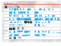
Automation solutions
An overview of the product range
Products listed in this catalogue
Product listed in other catalogues (see previous pages)
Control and
protection
Contactors
from 6 to 16A
Contactors
Contactors
from 9 to 150 A from 185 to 800 A
Modular contactors
Circuit-breakers
Rotary switch disconnector
Thermal overload relays
Measurement and
control relays
Ready-assembled
variable speed drives
Power supplies and transformers
Limit switches for safety
applications
Electromechanical pressure
and vacuum switches
Electronic pressure
and vacuum switches
TBX distributed I/O
Advantys STB
distributed I/O
Motor starters open version
Contactor and reversing
contactor breakers
Direct on-line starters,
enclosed version
Star-delta starters,
enclosed version
Connectors
Encoders
Inductive identification system
IP 67 splitter boxes
Telefast ® 2 pre-wired
system
Interfaces
Emergency stop
stations
Emergency stop
trip wire switches
Control and
protection
Soft starters open and
enclosed version
Soft start-soft stop units
for asynchronous motors
Variable speed drives for asynchronous motors
Photo-electric
detectors
Inductive, capacitive, magnet and ultrasonic
proximity sensors
Detection
Limit switches
Data processing
Twido programmable
controllers
Nano programmable
controllers
Micro
automation platform
Premium
automation platform
Quantum
automation platform
Momentum
automation platform
Human-Machine
dialogue
Control
relays
Electronic
timing relays
Zelio Logic
smart relays
tico 732
E
5
6
3
4
1
2
R
Control and signalling units
Cam switches
Control stations
Pendant control stations
Magelis operator dialogue terminals
Illuminated beacons
and indicator banks
Totalising timers
and counters
Foot switches
FactoryCast
Web solutions
FactoryCast HMI
Web solutions
Web and Internet technologies
Communication
Modbus TCP/X-Way communication architecture: TCP/IP Ethernet network, Modbus Plus network, Fipway network, Jnet network,
AS-Interfaces cabling system, Fipio bus, CANopen bus, Uni-Telway bus, Modbus bus, INTERBUS, Profibus DP, asynchronous serial links
Supervision
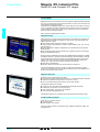
Magelis iPC industrial PC
Vijeo Look
supervisory software
Monitor Pro
supervisory software
Panel building
and cabling
accessories
Wall-mounted enclosures
Floor-standing enclosures Uprights, mounting plates, mounting rail,
cable ducting and cable clips
Prefadis service poles and posts,
lighting poles
Canalis busbar trunking for lighting distribution
Product reference index
Technical information
Prefabricated busbar systems and
power distribution systems
Tego Dial
Tego Power
Profil front panel
Terminal blocks
Cable ends
Power
distribution
Canalis busbar trunking for low and medium power distribution
Services
Schneider Electric worldwide
Canalis busbar trunking for high power distribution
Mobile distribution: Canalis track section and cable carriers
Marking accessories
Tools
Preventa safety
modules
4
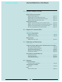
General contents
0
Human/Machine interfaces
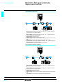
1 – Operator dialogue terminals
Selection guide . . . . . . . . . . . . . . . . . . . . . . . . . . . . . . . . . . . . . . . . . . . . . page 1/2
Magelis display units and terminals
Magelis compact display units . . . . . . . . . . . . . . . . . . . . . . . . . . . . . . page 1/10
Magelis display units with alphanumeric screen . . . . . . . . . . . . . . . . . page 1/14
Magelis display units and terminals with matrix screen . . . . . . . . . . . page 1/16
Magelis terminals with alphanumeric screen . . . . . . . . . . . . . . . . . . . page 1/18
Magelis graphic terminals
Magelis 5" terminals with keypad or touch-sensitive screen . . . . . . . . page 1/26
Magelis 5" and 10" terminals with touch-sensitive screen and keys . . page 1/28
Magelis 10" terminals with keypad or touch-sensitive screen . . . . . . . page 1/30
New Technology Magelis touch-sensitive terminals . . . . . . . . . . . . . page 1/36
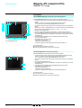
2 – Magelis iPC industrial PLCs
Selection guide . . . . . . . . . . . . . . . . . . . . . . . . . . . . . . . . . . . . . . . . . . . . . page 2/2
“All in one” compact products
Magelis Smart iPC range . . . . . . . . . . . . . . . . . . . . . . . . . . . . . . . . . . . page 2/9
Magelis Compact iPC range . . . . . . . . . . . . . . . . . . . . . . . . . . . . . . . . . page 2/9
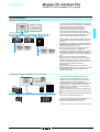
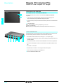
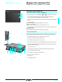
Modular products
Magelis Modular iPC range . . . . . . . . . . . . . . . . . . . . . . . . . . . . . . . . page 2/15
3 – Softwares and Web servers
Selection guide . . . . . . . . . . . . . . . . . . . . . . . . . . . . . . . . . . . . . . . . . . . . . page 3/2
Traditional architecture, HMI executed on dedicated terminal or PC platform
XBT L1003 development software . . . . . . . . . . . . . . . . . . . . . . . . . . . . page 3/4
Vijeo Designer configuration software . . . . . . . . . . . . . . . . . . . . . . . . . page 3/8
Vijeo Look supervisory software . . . . . . . . . . . . . . . . . . . . . . . . . . . . . page 3/10
Monitor Pro V7.2 supervisory software . . . . . . . . . . . . . . . . . . . . . . . . page 3/24
OFS data server software . . . . . . . . . . . . . . . . . . . . . . . . . . . . . . . . . . page 3/38
Web architecture, embedded HMI in PLC
Standard Web services . . . . . . . . . . . . . . . . . . . . . . . . . . . . . . . . . . . . page 3/44
FactoryCast Web server . . . . . . . . . . . . . . . . . . . . . . . . . . . . . . . . . . . page 3/46
FactoryCast HMI Web server . . . . . . . . . . . . . . . . . . . . . . . . . . . . . . . page 3/48
4 – Services
Technical information
Automation product certifications . . . . . . . . . . . . . . . . . . . . . . . . . . . . . page 4/2
Schneider Electric worldwide
Addresses . . . . . . . . . . . . . . . . . . . . . . . . . . . . . . . . . . . . . . . . . . . . . . . page 4/4
Index
Product reference index . . . . . . . . . . . . . . . . . . . . . . . . . . . . . . . . . . . page 4/10
5
1/0
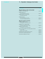
Contents
0
1 - Operator dialogue terminals
Selection guide . . . . . . . . . . . . . . . . . . . . . . . . . . . . . . . . . . . . . . . . . . . . . page 1/2
1
Magelis display units and terminals
b Magelis compact display units. . . . . . . . . . . . . . . . . . . . . . . . . . . . . . . . page 1/11
b Magelis display units
v with 2-line alphanumeric screen . . . . . . . . . . . . . . . . . . . . . . . . . . . . page 1/15
b Magelis display units and terminals
v with 8-line matrix screen . . . . . . . . . . . . . . . . . . . . . . . . . . . . . . . . . . page 1/17
b Magelis terminals
v with 2-line alphanumeric screen . . . . . . . . . . . . . . . . . . . . . . . . . . . . page 1/19
v with 2 or 4-line alphanumeric screen . . . . . . . . . . . . . . . . . . . . . . . . . page 1/21
Magelis graphic terminals
b Magelis 5" graphic terminals
v with keypad or touch-sensitive screen. . . . . . . . . . . . . . . . . . . . . . . . page 1/27
b Magelis 5" or 10" graphic terminals
v with touch-sensitive screen and keys . . . . . . . . . . . . . . . . . . . . . . . . page 1/29
b Magelis 10" graphic terminals
v with keypad or touch-sensitive screen. . . . . . . . . . . . . . . . . . . . . . . . page 1/31
b New Technology Magelis touch-sensitive graphic terminals
v with 5" screen . . . . . . . . . . . . . . . . . . . . . . . . . . . . . . . . . . . . . . . . . . page 1/37
v with 7", 10" or 12" screen. . . . . . . . . . . . . . . . . . . . . . . . . . . . . . . . . . page 1/39
b Separate parts for operator dialogue terminals . . . . . . . . . . . . . . . . . . . page 1/40
b Connection to Fipio bus/Fipway network. . . . . . . . . . . . . . . . . . . . . . . . page 1/43
b Connection to Modbus Plus network . . . . . . . . . . . . . . . . . . . . . . . . . . . page 1/45
1/1
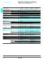
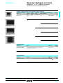
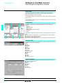
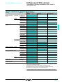
Selection guide
1
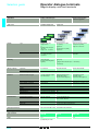
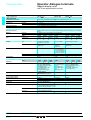
Operator dialogue terminals
Magelis display units and terminals
Applications
Display of text messages
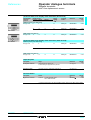
Type of unit
Compact display units
Display units
Type
Back-lit green LCD,
height 5.5 mm
or
Back-lit green, orange or
red LCD,
height 4.34…17.36 mm
Fluorescent green matrix
(5 x 7 pixels),
height 5 mm
or
Back-lit LCD (5 x 7 pixels),
height 9 mm
Back-lit monochrome matrix
LCD (240 x 64 pixels),
height 5.3 or 10.6 mm
Capacity
2 lines of 20 characters or
1 to 4 lines of 5 to 20
characters
2 lines of 20 characters
4 to 8 lines of 20 to 40
characters
Via keypad with
8 keys (4 with changeable
legends)
Display only
or
via keypad with 4 function keys + 1 service key
or
5 service keys
Application
512 Kb Flash
128 Kb/256 Kb Flash
384 Kb Flash EPROM
Extension via type II PCMCIA
–
Maximum number of pages
128/200 application pages
256 alarm pages
100/200 application pages
128/256 alarm pages
256 print-out form pages (1)
600 application pages
256 alarm pages
256 print-out form pages (1)
Variables per page
Representation of variables
40…50
Alphanumeric
Recipes
Curves
Alarm logs
Real-time clock
Alarm relay
–
–
–
Depending on model
Access to the PLC real-time clock
–
No
Asynchronous serial link
Downloadable protocols
RS 232 C/RS 485
Uni-Telway, Modbus
RS 232 C/RS 485/RS 422
Uni-Telway, Modbus, AEG and for PLC brands: Allen Bradley, GE
Fanuc, Omron, Siemens
Bus and networks
Printer link
–
–
AS-Interface using 22.5 pitch module
RS 232 C asynchronous serial link (1)
Display
Data entry
Memory capacity
Functions
Communication
Display of text messages
and/or semi-graphics
50
Alphanumeric, bargraph, gauge
Development software
XBT L1001 and XBT L1003 (under Windows 98, 2000 and XP)
Operating systems
Magelis
Type of terminal
XBT N
Pages
1/2
1/11
(1) Depending on model.
XBT H
XBT HM
1/15
1/17
1
1
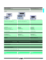
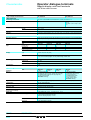
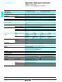
Display of text messages
Control and parametering of data
1
Display of text messages and/or semi-graphics
Control and parametering of data
1
Terminals
Fluorescent green matrix (5 x 7 pixels), height 5 mm
or
Back-lit LCD (5 x 7 pixels), height 9 mm
Fluorescent green matrix (5 x 7 pixels), height 5 mm
or
Back-lit LCD (5 x 7 pixels), height 5 mm
Back-lit monochrome matrix LCD (240 x 64 pixels),
height 5.3 or 10.6 mm
2 lines of 20 characters
2 or 4 lines of 40 characters
4 to 8 lines of 20 to 40 characters
Via keypad with
8 function keys + 9 service keys
or
keypad with 12 function keys
+ 10 service keys + 12 numeric keys
Via keypad with
24 function keys
+ 10 service keys
+ 12 alphanumeric keys
Via keypad with
12 function keys
10 service keys
12 numeric keys
4 soft function keys
256 Kb Flash EPROM
384 Kb Flash EPROM
512 Kb Flash EPROM
800 application pages
256 alarm pages
256 print-out form pages (1)
800 application pages
256 alarm pages
256 print-out form pages (1)
–
400 application pages
256 alarm pages
256 print-out form pages (1)
50
Alphanumeric
–
–
Depending on model
Access to the PLC real-time clock
No
Alphanumeric, bargraph, gauge
Built-in
Yes
Access to the PLC real-time clock
No
RS 232 C/RS 485/RS 422
Uni-Telway, Modbus, AEG and for PLC brands: Allen Bradley, GE Fanuc, Omron, Siemens
AS-Interface using 22.5 pitch module
RS 232 C asynchronous serial link (1)
–
AS-Interface using 22.5 pitch module
XBT L1001 and XBT L1003 (under Windows 98, 2000 and XP)
Magelis
XBT P
XBT E
XBT PM
1/19
1/21
1/17
1/3
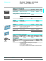
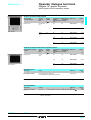
Selection guide
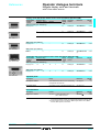
1
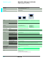
Operator dialogue terminals
Magelis graphic terminals
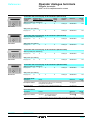
Applications
Display of text messages and graphic objects
Control and parametering of data
Type of unit
Graphic terminals
Display
Type
Back-lit monochrome LCD (320 x 240 pixels)
or Colour LCD STN with touch-sensitive screen (320 x 240 pixels) with optimum viewing angle
(1)
Capacity
5.7"
Data entry
Memory capacity
Functions
Communication
Via touch-sensitive screen
4 tactile feedback keys (XBT-FC)
Application
8 Mb Flash EPROM (via PCMCIA type II card)
Extension
By PCMCIA type II card, 8 or 16 Mb
Maximum number of pages
50 to 720 application, alarm, help and print-out form pages depending on the memory card used
(512 alarms maximum)
Variables per page
64
Representation of variables
Alphanumeric, bitmap, bargraph, gauge, potentiometer, selector
Recipes
Curves
Alarm logs
Real-time clock
Alarm relay
125 records maximum with 5000 values maximum
16
Yes
Access to the PLC real-time clock
Yes
Asynchronous serial link
Downloadable protocols
RS 232 C/RS 485/RS 422
Uni-Telway, Modbus, AEG and for PLC brands: Allen Bradley, GE Fanuc, Omron, Siemens
Bus and networks
Modbus Plus, Fipio/Fipway with add-on PCMCIA type III card, Ethernet 10/100 TCP/IP
(1) (2)
RS 232 C asynchronous serial link (depending on model)
Printer link
Development software
XBT L1003 (under Windows 98, 2000 and XP)
Operating systems
Magelis
Type of terminal
XBT F01/F03/FC
Pages
1/4
Via keypad with
10 static function keys
8 soft function keys
12 service keys
12 alphanumeric keys
1/27
(1) Depending on model.
(2) TCP/IP with Modbus protocol for XBT F.
(3) Uni-Telway version V2 for Nano/Micro/Premium PLCs.
1
1
1
1
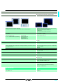
New Technology touch-sensitive graphic terminals
Back-lit monochrome LCD (640 x 480 pixels)
or Back-lit colour LCD TFT (640 x 480 pixels) with optimum viewing angle (1)
Back-lit monochrome (blue or black and white mode) or colour
LCD STN or LCD TFT (320 x 240 pixels)
or Back-lit colour LCD TFT (640 x 480 pixels or
800 x 600 pixels)
or Back-lit colour LCD STN (640 x 480 pixels)
9.5" (monochrome)
10.4" (colour)
5.7" (monochrome or colour)
7.4", 10.4" and 12.1" (colour)
Via touch-sensitive screen
Via keypad with
8, 12 or 16 tactile feedback keys (XBT-FC) (1) 12 static function keys
10 soft function keys
12 service keys
12 alphanumeric keys
Via touch-sensitive screen (1)
4…8 Mb (1)
By "Compact Flash" card, 16 or 32 Mb
30 to 480 application, alarm, help and print-out form pages depending on the memory card used Limited by the internal Flash memory capacity or "Compact Flash"
(512 alarms maximum)
card memory capacity
Unrestricted
Alphanumeric, bitmap, bargraph, gauge, button, light, clock,
flashing light, keypad
–
Yes, with log
Built-in
–
RS 232 C/RS 485
Uni-Telway (3), Modbus, Modbus TCP/IP
Ethernet (1), IEEE 802.3 10BaseT, RJ 45
For future use
VJD SPUL FUCDV10M (under Windows 2000 and XP)
Magelis (CPU 100 MHz RISC)
XBT F02/F03/FC
XBT G
1/27, 1/29 and 1/31
1/37 and 1/39
1/5
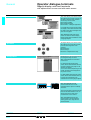
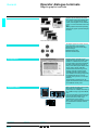
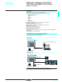
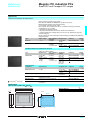
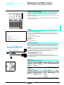
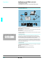
Presentation
1
Operator dialogue terminals
Architectures,
connection to automated systems
Architectures,
connection to automated systems
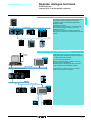
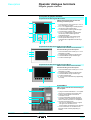
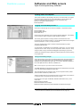
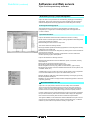
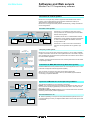
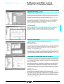
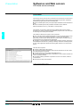
Magelis operator dialogue terminals communicate with automated system
equipment:
b Via serial link.
b Via fieldbus.
b In network architectures.
b By integration into an architecture with Ethernet TCP/IP network.
Point-to-point or multidrop connection with the PLC via serial link
All terminals incorporate an RS 232 C, RS 422/485
asynchronous serial link as standard.
The use of a Uni-TE, Modbus or KS protocol means that
communication can be set up easily with Schneider
Electric PLCs: Telemecanique, Modicon, April or A-Line.
Third party protocols provide connection to PLCs offered
by major manufacturers on the market:
b DF1, DH485 for Allen Bradley PLC5/SLC500 PLCs.
b SNPX for General Electric series 90 PLCs.
b Sysway for Omron C200 PLCs.
b AS511/3964R, MPI/PPI for Siemens Simatic S5/S7
PLCs.
Nano
Twido
XBT N
Micro
XBT HM
Uni-Telway
Quantum
Modbus
XBT P
XBT F
XBT G
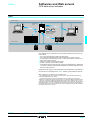
Connection to PLCs via fieldbus
Fipio
Premium
TBX
TBX
ATV 28
XBT F
1/6
The addition of a type III PCMCIA communication card to
XBT F graphic terminals enables connection to various
industrial buses:
b Fipio Bus.
b Modbus Plus Bus.
XBT F terminals with graphic screen use the bus master
PLC to provide operator dialogue and interactive control
of various devices connected to the bus.
Several terminals with graphic screen can be connected
on the same bus.
1
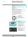
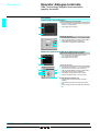
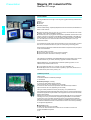
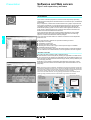
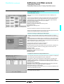
Presentation (continued)
Operator dialogue terminals
1
1
Architectures,
connection to automated systems
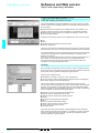
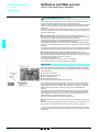
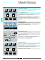
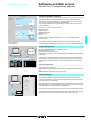
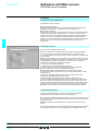
Integration in network architectures
The addition of a type III PCMCIA communication card to
XBT F graphic terminals means that they can be
integrated in single or multi-network architectures:
b Fipway network.
b Modbus Plus network.
The following can be connected on the same network:
b One terminal with graphic screen, which has a
multistation PLC view.
b Several terminals, which are totally independent.
Each terminal is assigned to controlling specific network
stations.
XBT F
Premium
Micro
Quantum
Fipio
Momentum
ATV 58
XBT F
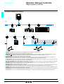
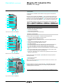
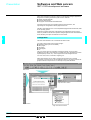
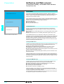
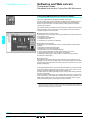
Integration in an architecture with Ethernet TCP/IP network
Network
manager
Automation platforms provide transparent routing of
X-Way and Uni-TE messages from a TCP/IP network to
an X-Way network and vice versa.
The various services offered are:
b Uni-TE TCP/IP messaging (for XBT F, access via
Ethernet TCP/IP X-Way protocol).
b Modbus TCP/IP messaging (for XBT G and XBT F,
access via Ethernet TCP/IP Modbus protocol).
XBT F
XBT G
Please refer to our “Modicon Premium automation
platform and PL7 software” catalogue.
Quantum + Web server
Premium + Web server
ATV 58
Ethernet TCP/IP
XBT F
Twido
Uni-Telway
Momentum
Modbus
Premium
XBT G
Micro
1/7
1
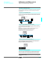
General
1
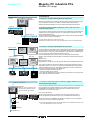
Operator dialogue terminals
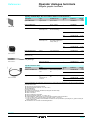
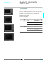
Magelis compact display units
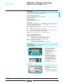
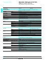
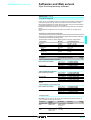
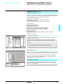
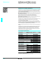
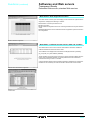
Presentation
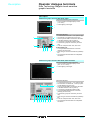
Magelis XBT N compact display units
are used to represent messages and
variables.
Various keys can be used to:
b modify variables,
b control the device,
b browse in a dialogue application.
XBT N200
XBT N401
All Magelis compact display units have
the same ergonomic user interface:
b 2 service keys ( , ), configurable
for contextual link or control,
v 2 service keys (ESC, ENTER), non
configurable,
v 4 customisable and configurable
keys, either as function keys (control
mode) or service keys (entry mode).
Operation
“Entry” customisation
“Control” customisation
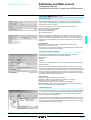
Configuration
Magelis compact display units can be
configured using the XBT L100p
software, in a Windows environment.
The XBT L100p software uses the
concept of pages: each page can be
viewed in its entirety. A 2 or 4-line
window, depending on the display unit
model to be configured, enables
viewing the screen of this virtual
terminal.
XBT N400
XBT N display units communicate with
PLCs via an integrated point-to-point or
multidrop serial link for XBT N401.
Communication
ESC
DEL
MOD ENTER
XBT N display unit
PLC
Characteristics:
page 1/10
1/8
References:
page.1/11
Dimensions:
page 1/46
The communication protocols used are
those of Schneider Electric PLCs (UniTelway, Modbus).
1
Operator dialogue terminals
Functions,
description
1
1
Magelis compact display units
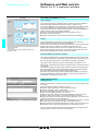
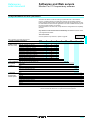
Functions
XBT N compact display units have, on the front panel, function keys and service keys
(according to “control” and “entry” customisation).
Function keys (F1, F2, F3, F4)
Function keys are defined for the whole application.
They can be used for:
b accessing a page,
b latching memory bits,
b toggling memory bits (ON/OFF).
Service keys
b Service keys , ESC, DEL,
,
, MOD, ENTER, are used for modifying the
parameters of the automated system.
They perform the following actions:
ESC
Cancel an entry, suspend or stop a current action, go back up a level in a
menu.
DEL
Delete the character selected in entry mode.
MOD
Select the variable field to enter. Authorise the entry of the next field, on
each press, from left to right and top to bottom.
ENTER Confirm a selection or entry, acknowledge an alarm.
b The “arrow” keys are used to:
v change page within a menu,
v display the current alarms,
v change a digit in a variable field being entered,
v activate the function associated with a functional link,
v move up and down within a page (XBT N40p),
v select the value of a digit,
v select a value from a list of choices,
v increment or decrement the value of a variable field.
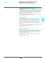
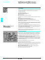
Description
XBT N compact display units comprise:
On the front panel
1 A communication monitoring
indicator light (XBT N401).
2
A back-lit LCD display.
3
3 Two control or contextual link keys,
non configurable.
4
4 An “Alarm” indicator light
(XBT N401).
5 Six service keys, 4 of which
(framed) are configurable as
function keys and fitted with 2
indicator lights (XBT N401).
6
6 A customisable “entry” legend.
7 A customisable “control” legend
7
F1, F2, F3, F4.
8
8 A customisable blank legend.
1
2
3
5
On the rear
1 A 25-way SUB-D type serial link
(XBT N401).
2 An RJ 45 serial link (XBT N200 and
XBT N400).
3 A plug-in screw terminal block for
c 24 V power supply (XBT N401).
1
Characteristics:
page 1/10
References:
page.1/11
2
3
Dimensions:
page 1/46
1/9
1
Characteristics
1
Operator dialogue terminals
Magelis compact display units
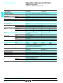
Type of display unit
XBT N200
XBT N400
XBT N401
XBT NU400
Environment
Conforming to standards
Product certifications
Ambient air temperature
Maximum relative humidity
Degree of protection
°C
°C
%
For operation
For storage
Front panel
Rear panel
Shock resistance
Vibration resistance
E.S.D.
Electromagnetic interference
Electrical interference
IEC 61131-2, IEC 60068-2-6, IEC 60068-2-27, UL 508, CSA C22-2 n° 14
e, UL, CSA, class 1 Div 2 (UL and CSA)
0…+ 55
- 20…+ 60
0…85 (without condensation)
IP 65, conforming to IEC 60529, Nema 4X (“outdoor use”)
IP 20, conforming to IEC 60529
Conforming to IEC 60068-2-27; semi-sinusoidal pulse 11 ms, 15 gn on the 3 axes
Conforming to IEC 60068-2-6 and marine certification; ± 3.5 mm; 2…8.45 Hz; 1 gn
8.75…150 Hz
Conforming to IEC 61000-4-2, level 3
Conforming to IEC 61000-4-3, 10 V/m
Conforming to IEC 61000-4-4, level 3
Mechanical characteristics
Mounting and fixing
Material
Flush mounted, fixed by 2 spring clips (included), pressure mounted for 1.5 to 6 mm thick
panels
Polyester
Polycarbonate/Polybutylene Terephthalate
Polyester
8 keys (6 configurable and 4 with changeable legends)
Screen protection
Front frame
Keypad
Keys
Electrical characteristics
Power supply
Voltage
Voltage limits
Ripple
%
Consumption
c 5 V via PLC terminal port
–
–
–
c 24 V
c 18…30 V
5 maximum
5 W max.
Operating characteristics
Display
Signalling
Dialogue application
Memory
Transmission
Downloadable protocols
Real-time clock
Connection
Type
Green back-lit LCD
Capacity
(height x width)
2 lines of 20
characters
(5.55 x 3.2 mm)
–
–
4 LEDs
–
128 application
200 application pages (25 lines/page max.)
pages (2 lines/page 256 alarm pages (25 lines/page max.)
max.)
512 Kb Flash
RS 232 C/RS 485
Uni-Telway, Modbus
Modbus
Access to the PLC real-time clock
By the PLC terminal port connecting cable Plug-in terminal block, 3 screw terminals
(XBT Z978)
(pitched at 5.08 mm)
Maximum clamping capacity: 1.5 mm2
Female RJ 45 (RS 232 C/RS 485)
25-way SUB-D type
Point-to-point
Multidrop
No
Mini-DIN (for future No
use)
Number of pages
Asynchronous serial link
Power supply
Serial port
Printer port
Presentation:
pages 1/8 and 1/9
1/10
Dimensions:
page 1/46
Connector
Connection
Green back-lit LCD
(122 x 32 pixels)
Green, orange or
Green back-lit LCD
red back-lit LCD
(122 x 32 pixels)
(122 x 32 pixels)
From 1 line of 5 characters (17.36 x 11.8 mm) to 4 lines of
20 characters (4.34 x 2.95 mm)
1
References
1
Operator dialogue terminals
1
Magelis compact display units
Magelis compact display units
Downloadable
exchange protocol
Compatible PLCs
Supply voltage
Reference
Weight
kg
521364
Display unit with 2 lines of 20 characters (with alphanumeric screen)
Uni-Telway, Modbus
c 5 V via PLC
terminal port
XBT N200
0.360
Twido, Nano, Micro, Premium
c 5 V via PLC
terminal port
XBT N400
0.360
Twido (1), Nano, Micro, Premium,
TSX series 7, Momentum, Quantum
Other Modus slave equipment
TeSys model U motor starters (2)
Altivar drives
c 24 V external
supply
XBT N401
0.380
c 24 V external
supply
XBT NU400
0.380
Twido, Nano, Micro, Premium
Display units with 4 lines of 20 characters (with matrix screen)
XBT N200
521366
Uni-Telway, Modbus
Modbus
XBT N401
Software
Description
Configuration software
Operating system
Windows 98, 2000 or XP
Reference
See page 3/7
–
Accessories (3)
521377
Description
Accessory for flush
mounting
MOD
ESC
Protective sheets
DEL
XBT ZN01
For use with
Reference
Kit for applications requiring a higher degree
of protection or customisation of the console,
using a flat metal strip (not included)
10 peel off sheets
All XBT N
XBT ZN01
Weight
kg
–
All XBT N
XBT ZN02
–
10 sheets of 6 legends
XBT N200/400
XBL YN00
–
XBT N401/NU400
XBL YN01
–
Length Reference
m
2.5
XBT Z978
Weight
kg
0.180
521373
Sheets of changeable
legends
Description
MOD
ESC
ENTE
DEL
521372
XBT ZN02
R
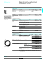
Cables and connection accessories (4)
Description
Compatibility Type of
connector
RJ 45
Cable for Twido, Nano,
XBT N p00
Mini-DIN
Micro and Premium PLCs
Physical
link
RS 485
Protocol
Modbus,
Uni-Telway
Documentation
Description
XBT Z978
Magelis range user’s
manual
Format
A5
To order separately to the XBT L100pM
CD-ROM
Reference
(5)
XBT X000pp
Weight
kg
0.700
(1) Connection via integrated port or optional serial port on the Twido PLC.
(2) Factory preloaded application for monitoring, diagnostics and adjustment of 1 to 8 TeSys
model U motor starters.
(3) For other accessories, see pages 1/40 and 1/41.
(4) For other cables and connection accessories, see page 1/41.
(5) Add the following suffix to the reference: EN for English, FR for French, DE for German, ES for
Spanish, 1T for Italian.
Presentation:
pages 1/8 and 1/9
Dimensions:
page 1/46
1/11
1
General
1
Operator dialogue terminals
Magelis display units and terminals
with alphanumeric screen and with matrix screen
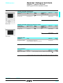
Presentation
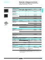
XBT H/P/E display units and terminals
with alphanumeric screen are used to
represent messages and variables.
Various keys can be used:
b to modify variables,
b to control the device,
b to browse in a dialogue application.
XBT H
XBT P
For models which have a printer output,
the display units and terminals can also
be used to print alarm messages and
print-out form pages.
XBT E
XBT HM/PM terminals with matrix
screen can also be used to display
bitmap images and animated bar chart
and gauge objects.
XBT HM
XBT PM
Operation
All Magelis display units and terminals
with alphanumeric and matrix screen
have the same ergonomic user
interface:
b function keys,
b service keys,
b numeric or alphanumeric keys.
Configuration
Magelis display units and terminals can
be configured using the same
XBT L1003 software in a Windows
environment.
For terminals with alphanumeric
screen, XBT L1003 software uses the
concept of pages: each page can be
viewed in its entirety.
A 2 or 4-line window, depending on the
model, simulates what will appear on
the product screen.
For XBT HM/PM terminals with matrix
screen, XBT L1003 software offers up
to 8 lines of 40 characters, and
animated bar chart and gauge objects.
Communication
XBT HM
PLC
XBT H/P/E/HM/PM terminals
communicate with PLCs via an
integrated point-to-point or multidrop
serial link.
The communication protocols used are
those of Schneider Electric PLCs, as
well as those of the other major
manufacturers on the market.
XBT H/P/HM/PM terminals also
communicate on the AS-Interface
cabling system bus using the 22.5
pitched module.
Characteristics:
pages 1/14, 1/18, 1/20 and 1/16
1/12
References:
pages 1/15, 1/19, 1/21 and 1/17
Dimensions:
page 1/46
1
Operator dialogue terminals
Functions,
description
1
1
Magelis display units and terminals
with alphanumeric screen and with matrix screen
Functions
XBT H/P/E/HM/PM display units and terminals have (depending on the model)
function keys and service keys on the front panel.
Function keys
Function keys are defined for the whole application. They can be used for:
b accessing a page,
b latching memory bits,
b toggling memory bits (ON/OFF).
Service keys
Services keys are the “arrow keys” and the control keys combined, and are used for
modifying the parameters of the automated system.
The control keys are used to perform the following actions:
ENTER Confirm a selection or entry, acknowledge an alarm.
MOD
Change to the mode for entering pages, passwords, fields or graphic objects.
ESC
Cancel an entry, suspend or stop a current action.
SHIFT Access the second of the dual key functions.
MENU Access a menu containing the operating functions.
HOME Return to the entry point of the current menu.
Example: return to the first page of the application.
SYST Access the confidential mode which contains the setup functions.
ALARM View the alarms.
PRINT Print.
The “arrow” keys are used to:
b change page within a menu,
b move within a page,
b select the value of a digit,
b select a value from a list of choices,
b increment or decrement the value of a variable
field, when used with the SHIFT key.
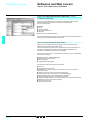
Description
XBT H/P/E/HM/PM display units and terminals comprise:
On the front panel
1 A communication monitoring indicator light.
2 A keypad activity indicator light (depending on
3
model).
3 Fluorescent or back-lit LCD display.
4 Function keys with indicator light and
changeable legends.
5 Service keys with indicator light.
6 Twelve numeric keys (for XBT-P02pppp)
6
Twelve alphanumeric keys (0…9, +/-, .)
associated with 3 alphabetical access keys
(A…Z) for XBT E.
1
2
4
5
On the rear
1 A plug-in screw terminal block for c 24 V power
supply and a connection for the alarm relay
(depending on model).
2 A 25-way female SUB-D connector for
connection to PLCs, FT2100 configuration
terminals or PC compatibles.
3 A 9-way male SUB-D connector for the printer
connection (depending on model).
1
Characteristics:
pages 1/14, 1/18, 1/20 and 1/16
2
3
References:
pages 1/15, 1/19, 1/21 and 1/17
Dimensions:
page 1/46
1/13
1
Characteristics
1
Operator dialogue terminals
1
Magelis display units
with 2-line alphanumeric screen
XBT H0p2p10
Type of display unit
XBT H811050
XBT H0 p1010
Environment
Conforming to standards
Product certifications
Temperature
Operation
Storage
Degree of protection
Vibration
IEC 61131-2, IEC 60068-2-6, IEC 60068-2-27, UL 508, CSA C22-2 n° 14
e, UL, CSA
0…+ 50 °C
- 40…+ 70 °C
- 20…+ 60 °C
IP 65, conforming to IEC 60529, Nema 4
Conforming to IEC 60068-2-6; 2…11.2 Hz at 1 mm; 11.2…150 Hz, 1 gn for 3 hours per axis
Mechanical characteristics
Mounting and fixing
Material
Keys
Enclosure
Keypad, screen protection
XBT H
Function keys
Service keys
Flush mounted, fixed by 4 or 6 locking clips (included), pressure mounted (on 1 to
panel)
Polyphenyl oxide, 10% glass fibre (PPO GFN1 SE1)
Anti-UV treated toughened polyester (Autoflex EB AG)
002010
022010
012p10
811050
001010
021010
No keys
4
No keys
No keys
No keys
4
No keys
1
5
5
No keys
1
6 mm thick
011010
No keys
5
Electrical characteristics
Display
Type
Capacity
Power supply
Fluorescent green matrix
characters (5 x 7 pixels)
2 lines of 20 characters,
height 5 mm
Voltage
c 24 V non isolated
Voltage limits
Ripple
18…30 V
5% maximum
10 W
Consumption
LCD (5 x 7 pixels)
Back-lit LCD (5 x 7 pixels)
2 lines of 20
2 lines of 20 characters,
characters,
height 9 mm
height 9 mm
c 24 V non isolated
c 24 V non isolated
(during configuration)
c 5 V via Nano/Micro/
Premium PLC terminal
port (during operation)
1.5 W
10 W
811050
–
128 Kb Flash EPROM
100 application pages
approx.
(2 lines/page max.)
128 available alarm
pages
(2 lines/page max.)
001010
021010
011010
1 LED
6 LEDs
4 LEDs
128 Kb Flash EPROM,
(256 Kb for XBT H011010)
200 application pages approx.
(2 lines/page max.)
256 available alarm pages
(2 lines/page max.)
–
–
RS 232 C/RS 485
RS 232 C/RS 485/RS 422
Operating characteristics
XBT H
Signalling
Memory
Log function
Transmission
(asynchronous serial link)
Downloadable protocol
Real-time clock
Printer link
(asynchronous serial link)
Connection
References:
page 1/15
1/14
002010
022010
012p10
1 LED
6 LEDs
4 LEDs
128 Kb Flash EPROM,
(256 Kb for XBT H012p10)
200 application pages approx.
(2 lines/page max.)
256 available alarm pages
(2 lines/page max.)
256 print-out form pages
for XBT H012110
Possibility of storing alarm pages
(XBT H012110) for print-out
RS 232 C/RS 485/RS 422
Multiple
Uni-Telway
See pages 1/12 and 1/40
Access to the PLC real-time clock
RS 232 C (XBT H012110)
–
Serial port
Plug-in terminal block
3 screw terminals (pitched at 5.08 mm)
Maximum clamping capacity: 1.5 mm2
25-way female SUB-D connector
Printer port
9-way male SUB-D connector
Power supply
Dimensions, mounting:
page 1/46
–
Multiple
–
–
References
1
Operator dialogue terminals
1
Magelis display units
with 2-line alphanumeric screen
Display units with 2 lines of 20 characters (fluorescent)
802907
Downloadable
exchange
protocol
Number of keys
Function Service
Supply
voltage
Vc
Language
version
Reference
Numeric
Weight
kg
Without printer port, without log
See page 1/40
802905
XBT H00 p010
–
–
–
24
Multilingual
XBT H002010
0.600
4
1
–
24
Multilingual
XBT H022010
0.600
–
5
–
24
Multilingual
XBT H012010
0.600
5
–
24
Multilingual
XBT H012110
0.600
Multilingual
24 and 5 via
terminal port on
the Twido/
Nano/Micro/
Premium PLC
XBT H811050
0.600
With printer port, with log
See page 1/40
XBT H02p010
–
Display units with 2 lines of 20 characters (LCD)
Without printer port, without log
802906
Modbus,
Uni-Telway
See page 1/40
–
5
–
Display units with 2 lines of 20 characters (back-lit LCD)
Without printer port, without log
XBT H01 pp10
See page 1/40
–
–
–
24
Multilingual
XBT H001010
0.600
4
1
–
24
Multilingual
XBT H021010
0.600
–
5
–
24
Multilingual
XBT H011010
0.600
Separate parts
Description
Usage
Reference
Development software
Under Windows 98, 2000 or XP,
for downloading the application and protocols
See page 3/7
Connecting cables
Connection to PLCs, configuration terminals, etc.
See page 1/41
Format
Reference
(1)
XBT X000pp
Weight
kg
–
–
Documentation
Description
Magelis
user’s manual
A5 bound
To order separately to the
XBT L100 pM CD-ROM
Weight
kg
0.700
(1) Add the following suffix to the reference: EN for English, FR for French, DE for German, ES for
Spanish, 1T for Italian.
Characteristics:
page 1/14
Dimensions, mounting:
page 1/46
1/15
1
Characteristics
1
Operator dialogue terminals
Magelis display units and terminals
with 8-line matrix screen
Type of display unit and terminal
XBT HM0p7 p10
XBT PM027p10
Environment
Conforming to standards
Product certifications
Temperature
IEC 61131-2, IEC 60068-2-6, IEC 60068-2-27, UL 508, CSA C22-2 n° 14
e, UL, CSA
e, UL Class 1, Div 2. Group A, B,
C, D-T5,
CSA Class 1, Div 2. Group A, B, C,
D-T5
Operation
Storage
Degree of protection
Vibration
0…+ 50 °C
- 20…+ 60 °C
IP 65, conforming to IEC 60529, Nema 4
Conforming to IEC 60068-2-6; 2 to 11.2 Hz at 1 mm; 11.2 to 150 Hz, 1 gn for 3 hours per axis
Mechanical characteristics
Mounting and fixing
Material
Keys
Enclosure
Flush mounted, fixed by 6 spring clips (included), pressure mounted (on 1.6 to 6 mm thick panel)
Polyphenyl oxide, 10% glass fibre (PPO GFN1 SE1)
Keypad
Screen protection
XBT
Function keys
Service keys
Numeric keys
Dynamic function keys
Anti-UV treated toughened polyester (Autoflex EB AG)
Glass, 3 mm thick
HM007010
HM027010
HM017p10
–
4
–
–
1
5
–
–
–
–
–
PM027p10
12
10
12
4
Electrical characteristics
Display
Power supply
Type
Back-lit LCD (240 x 64 pixels)
Capacity
8 lines of 40 characters (height 5.3 mm) single height,
4 lines of 20 characters (height 10.6 mm) double height, double width
Voltage
Voltage limits
c 24 V non isolated
18…30 V
Ripple
5% maximum
15 W
Consumption
Operating characteristics
XBT
Signalling
Memory
Log function
HM007010
HM027010
HM017p10
1 LED
6 LEDs
4 LEDs
384 Kb Flash EPROM
600 application pages approx. (8 lines per page max.)
256 available alarm pages (8 lines per page max.)
256 print-out form pages
(XBT HM017110 only)
PM027p10
21 LEDs
512 Kb Flash EPROM
800 application pages approx.
(8 lines per page max.)
256 available alarm pages
(8 lines per page max.)
256 print-out form pages
(XBT PM027110 only)
Possibility of storing alarm pages (XBT HM017110 and XBT PM027110) for print-out
Transmission
(asynchronous serial link)
Downloadable protocol
Real-time clock
RS 232 C/RS 485/RS 422
Printer link
(asynchronous serial link)
Alarm relay
Connection
RS 232 C (XBT HM017110 and XBT PM027110)
References:
page 1/17
1/16
Multiple (see pages 1/12 and 1/40)
Access to the PLC real-time clock
Power supply
1 N/O contact (min. 1 mA/c 5 V, max. 0.5 A/ c 24 V)
Plug-in terminal block
3 screw terminals (pitched at 5.08 mm)
Maximum clamping capacity: 1.5 mm2
Serial port
25-way female SUB-D connector
Printer port
9-way male SUB-D connector
Dimensions, mounting:
page 1/46
1
References
1
Operator dialogue terminals
1
Magelis display units and terminals
with 8-line matrix screen
Display units with 8-line matrix screen of 40 characters (back-lit LCD)
802943
Downloadable
exchange
protocol
Number of keys
Function
Service
Supply
voltage
Vc
Language
version
Reference
Numeric
Weight
kg
Without printer port, without log
See page 1/40
–
–
–
24
Multilingual
XBT HM007010
0.600
4
1
–
24
Multilingual
XBT HM027010
0.600
–
5
–
24
Multilingual
XBT HM017010
0.600
5
–
24
Multilingual
XBT HM017110
0.600
5
–
24
Multilingual
XBT HM017010A8
(1)
0.600
802942
XBT HM027010
XBT HM007010
802944
With printer port, with log
See page 1/40
XBT HM017p10
With printer port, with log
Modbus
105080
–
–
Terminals with 8-line matrix screen of 40 characters (back-lit LCD)
XBT HM017010A8
Downloadable
exchange
protocol
Number of keys
Function Service
Dynamic
Supply
voltage
Vc
Language
version
Reference
Numeric
Weight
kg
10
12
4
24
Multilingual
XBT PM027010
0.600
10
12
4
24
Multilingual
XBT PM027110
0.600
Without printer port, without log
12
802945
See page 1/40
With printer port, with log
See page 1/40
12
XBT PM027 p10
Separate parts
Description
Usage
Reference
Development software
Under Windows 98, 2000 or XP, for downloading
the application and protocols
See page 3/7
Connecting cables
Connection to PLCs, configuration terminals, etc.
See page 1/41
Format
Reference
(2)
XBT X000pp
Weight
kg
–
–
Documentation
Description
Magelis user’s manual
A5 bound
To order separately to the
XBT L100 pM CD-ROM
Weight
kg
0.700
(1) Factory preloaded application for monitoring, diagnostics and adjustment of 1 to
8 ATV 28/ATV 58 drives. Display unit supplied with XBT Z908 connecting cable.
(2) Add the following suffix to the reference: EN for English, FR for French, DE for
German, ES for Spanish, 1T for Italian.
Characteristics:
page 1/16
Dimensions, mounting:
page 1/46
1/17
1
Characteristics
1
Operator dialogue terminals
Magelis terminals
with 2-line alphanumeric screen
XBT P0p2p10
Type of terminal
XBT P0p1p10
Environment
Conforming to standards
Product certifications
Temperature
IEC 61131-2, IEC 60068-2-6, IEC 60068-2-27, UL 508, CSA C22-2 n° 14
e, UL, CSA
Operation
Storage
Degree of protection
Vibration
0…+ 50 °C
- 40…+ 70 °C
- 20…+ 60 °C
IP 65, conforming to IEC 60529, Nema 4
Conforming to IEC 60068-2-6; 2 to 11.2 Hz at 1 mm; 11.2 to 150 Hz, 1 gn for 3 hours per axis
Mechanical characteristics
Mounting and fixing
Material
Keys
Enclosure
Keypad, screen protection
Flush mounted, fixed by 4 or 6 locking clips (included), pressure mounted (on 1 to 6 mm thick
panel)
Polyphenyl oxide, 10% glass fibre (PPO GFN1 SE1)
Anti-UV treated toughened polyester (Autoflex EB AG)
XBT P
Function keys
Service keys
Numeric keys
012010
8
9
–
022p10
12
10
12
011010
8
9
–
021p10
12
10
12
Electrical characteristics
Display
Type
Power supply
Capacity
Voltage
Fluorescent green matrix characters
(5 x 7 pixels)
2 lines of 20 characters, height 5 mm
c 24 V non isolated
Voltage limits
Ripple
18…30 V
5% maximum
Consumption
Back-lit LCD (5 x 7 pixels)
2 lines of 20 characters, height 9 mm
10 W
Operating characteristics
XBT P
Signalling
Memory
Log function
Transmission
(asynchronous serial link)
Downloadable protocol
Real-time clock
Printer link
(asynchronous serial link)
Connection
Possibility of storing alarm pages
(XBT P022110)
RS 232 C/RS 485/RS 422
Multiple (see pages 1/12 and 1/40)
Access to the PLC real-time clock
RS 232 C (XBT P022110)
Power supply
Serial port
Printer port
References:
page 1/19
1/18
012010
022p10
011010
17 LEDs
21 LEDs
17 LEDs
256 Kb Flash EPROM
400 application pages approximately (25 lines per page max.)
256 available alarm pages (25 lines per page max.)
256 print-out form pages (XBT P02p110 only)
Dimensions, mounting:
page 1/46
Plug-in terminal block
3 screw terminals (pitched at 5.08 mm)
Maximum clamping capacity: 1.5 mm2
25-way female SUB-D connector
9-way male SUB-D connector
021p10
21 LEDs
Possibility of storing alarm pages
(XBT P021110)
RS 232 C (XBT P021110)
1
References
1
Operator dialogue terminals
1
Magelis terminals
with 2-line alphanumeric screen
Terminals with 2-line display of 20 characters (fluorescent)
Downloadable
exchange
protocol
Number of keys
Function
Service
Supply
voltage
Vc
Language
version
Reference
Numeric
Weight
kg
Without printer port, without log
8
9
–
24
Multilingual
XBT P012010
0.800
12
10
12
24
Multilingual
XBT P022010
0.800
10
12
24
Multilingual
XBT P022110
0.800
802908
See page 1/40
XBT P01p010
With printer port, with log
12
802908
See page 1/40
Terminals with 2-line display of 20 characters (back-lit LCD)
XBT P02pp10
Without printer port, without log
See page 1/40
8
9
–
24
Multilingual
XBT P011010
0.800
12
10
12
24
Multilingual
XBT P021010
0.800
10
12
24
Multilingual
XBT P021110
0.800
With printer port, with log
See page 1/40
12
Separate parts
Description
Usage
Reference
Development software
Under Windows 98, 2000 or XP,
for downloading the application and protocols
See page 3/7
Connecting cables
Connection to PLCs, configuration terminals, etc.
See page 1/41
Format
Reference
(3)
XBT X000pp
Weight
kg
–
–
Documentation
Description
Magelis user’s manual
A5 bound
To order separately to the
XBT L100pM CD-ROM
Weight
kg
0.700
(1) Add the following suffix to the reference: EN for English, FR for French, DE for German, ES for
Spanish, 1T for Italian.
Characteristics:
page 1/18
Dimensions, mounting:
page 1/46
1/19
1
Characteristics
1
Operator dialogue terminals
Magelis terminals
with 2 or 4-line alphanumeric screen
XBT E014p10/XBT E016p10
Type of terminal
XBT E013p10/XBT E015 p10
Environment
Conforming to standards
Product certifications
Temperature
IEC 61131-2, IEC 60068-2-6, IEC 60068-2-27, UL 508, CSA C22-2 n° 14
e, UL, CSA
Operation
Storage
Degree of protection
Vibration
0…+ 50 °C
- 40…+ 70 °C
- 20…+ 60 °C
IP 65, conforming to IEC 60529, Nema 4
Conforming to IEC 60068-2-6; 2 to 11.2 Hz at 1 mm; 11.2 to 150 Hz, 1 gn for 3 hours per axis
Mechanical characteristics
Mounting and fixing
Material
Enclosure
Flush mounted, fixed by 4 or 6 locking clips (included), pressure mounted (on 1 to 6 mm thick
panel)
Polyphenyl oxide, 10% glass fibre (PPO GFN1 SE1)
Keys
Keypad, screen protection
Function keys
Anti-UV treated toughened polyester (Autoflex EB AG)
24
Service keys
Alphanumeric keys
10
12
Electrical characteristics
Display
XBT E
Type
Capacity
Power supply
014p10
E016p10
Fluorescent green matrix characters
(5 x 7 pixels)
2 lines of
4 lines of
40 characters,
40 characters,
height 5 mm
height 5 mm
Voltage
Voltage limits
c 24 V non isolated
18…30 V
Ripple
5% maximum
20 W
Consumption
013p10
015p10
Back-lit LCD (5 x 7 pixels)
2 lines of
40 characters,
height 5 mm
4 lines of
40 characters,
height 5 mm
10 W
Operating characteristics
Signalling
Memory
33 LEDs, 1 buzzer (taking into account operation of keys)
384 Kb Flash EPROM
800 application pages approximately (25 lines per page max.)
256 available alarm pages (25 lines per page max.)
256 print-out form pages (XBT E01p110 only)
Log function
Transmission
(asynchronous serial link)
Downloadable protocol
Real-time clock
Possibility of storing alarm pages
RS 232 C/RS 485/RS 422
Printer link
(asynchronous serial link)
Alarm relay
Connection
RS 232 C (XBT E014110/XBT E016110)
References:
page 1/21
1/20
Multiple (see pages 1/12 and 1/40)
Built-in
RS 232 C (XBT E013110/XBT E015110)
Power supply and
alarm relay
1 N/O contact (min. 1 mA/c 5 V, max. 0.5 A/c 24 V)
Plug-in terminal block
5 screw terminals (pitched at 5.08 mm)
Maximum clamping capacity: 1.5 mm2
Serial port
25-way female SUB-D connector
Printer port
9-way male SUB-D connector
Dimensions, mounting:
page 1/46
1
References
1
Operator dialogue terminals
1
Magelis terminals
with 2 or 4-line alphanumeric screen
Terminals with 2-line display of 40 characters (fluorescent)
802910
Downloadable
exchange
protocol
Number of keys
Function
Service
Alphanumeric
Supply
voltage
Vc
Language
version
Reference
Weight
kg
Without printer port, without log
See page 1/40
24
10
12
24
Multilingual
XBT E014010
1.000
10
12
24
Multilingual
XBT E014110
1.000
XBT E014p10
With printer port, with log
See page 1/40
24
802911
Terminals with 4-line display of 40 characters (fluorescent)
Without printer port, without log
See page 1/40
XBT E016p10
24
10
12
24
Multilingual
XBT E016010
1.000
10
12
24
Multilingual
XBT E016110
1.000
With printer port, with log
See page 1/40
24
Terminals with 2-line display of 40 characters (back-lit LCD)
802912
Without printer port, without log
See page 1/40
XBT E013p10
24
10
12
24
Multilingual
XBT E013010
1.000
10
12
24
Multilingual
XBT E013110
1.000
With printer port, with log
See page 1/40
24
Terminals with 4-line display of 40 characters (back-lit LCD)
802913
Without printer port, without log
See page 1/40
24
10
12
24
Multilingual
XBT E015010
1.000
10
12
24
Multilingual
XBT E015110
1.000
With printer port, with log
XBT E015p10
See page 1/40
24
Separate parts
Description
Usage
Reference
Development software
Under Windows 98, 2000 or XP, for downloading
the application and protocols
See page 3/7
Connecting cables
Connection to PLCs, configuration terminals, etc.
See page 1/41
Format
Reference
(1)
XBT X000pp
Weight
kg
–
–
Documentation
Description
Magelis user’s manual
A5 bound
To order separately to the
XBT L100 pM CD-ROM
Weight
kg
0.700
(1) Add the following suffix to the reference: EN for English, FR for French, DE for German, ES for
Spanish, 1T for Italian.
Characteristics:
page 1/20
Dimensions, mounting:
page 1/46
1/21
1
General
1
Operator dialogue terminals
Magelis graphic terminals
Presentation
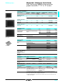
XBT F01/F03
XBT F02/F03
Magelis operator dialogue terminals
with graphic screen are available with
5.7" or 10.4" monochrome or colour
screen, with a keypad, a touch-sensitive
screen or a touch-sensitive screen and
keys.
XBT F graphic terminals are specially
designed for graphic operator dialogue
functions.
XBT FC02/04/06/08
Operation
All Magelis graphic terminals have the
same ergonomic user interface:
b static and dynamic function keys,
b service keys,
b alphanumeric keys,
b touch-sensitive keys.
Configuration
Magelis graphic terminals can be
configured using the same XBT L1003
software in a Windows environment.
For both graphic terminals and stations,
the XBT L1003 software provides a
library of animated graphic objects such
as bar charts, gauges, selectors,
potentiometers and trending curves.
A library of bitmap symbols is also
available with XBT L1003 software.
The variable for animating an object can
be selected directly from a list of
symbols given by the PL7 or Concept
software.
The application programme for the
graphic terminals and stations is stored
on a PCMCIA memory card.
Communication
XBT F graphic terminals communicate
with PLCs via an integrated
point-to-point or multidrop serial link, or
via a fieldbus using a type III PCMCIA
card.
The communication protocols used are
those of Schneider Electric PLCs, as
well as those of the other major
manufacturers on the market.
XBT F (10.4’’) graphic terminals can also
be connected to an Ethernet TCP/IP
network.
PLC
XBT F
PLC
Characteristics:
page 1/26
1/22
References:
page 1/27
Dimensions:
page 1/47
1
Functions
1
Operator dialogue terminals
1
Magelis graphic terminals
Functions
XBT F graphic terminals have the following functions:
b display of animated synoptic screens, control, modification of numeric and
alphanumeric variables,
b display of a service line (status and alarm bar) with the current time,
b dynamic visualisation of operating data (settings, measurements, recipes,
maintenance messages) and process errors,
b control via dynamic or static function keys,
b scaling of analogue variables,
b real-time and trending curves,
b alarm log and management of alarm groups,
b management of help pages, form pages, recipe pages,
b pages can be called up by the user or by the PLC,
b three levels of password,
b printing of form pages, date and time stamped log and alarms,
b communication protocol application support in the type II PCMCIA application
memory card.
The role of the function keys is defined using the XBT L1003 software. Modifications
cannot be made during operation.
Each function key can be associated with an internal bit of the PLC application.
Static function keys
Static function keys are defined for the whole application.
They can be used for:
b accessing a page,
b setting latching memory bits,
b toggling memory bits (ON/OFF).
Static keys can be marked with changeable legends.
Dynamic function and touch-sensitive keys
Dynamic function and touch-sensitive keys are associated with a page. Their role
can therefore differ from one page to another.
They can be used for:
b accessing a page,
b setting latching memory bits,
b toggling memory bits (ON/OFF),
b access to the modification of a value,
b direct writing.
Each dynamic key and touch-sensitive key can be assigned a label or icon illustrating
its function.
On touch-sensitive terminals, the touch-sensitive zones function in a similar way to
the dynamic keys on keypad terminals.
Characteristics:
page 1/26
References:
page 1/27
Dimensions:
page 1/47
1/23
1
Functions
(continued)
1
Operator dialogue terminals
1
Magelis graphic terminals
Functions (continued)
Service keys
Service keys are the “arrow” keys and the control keys combined, and are used for
modifying the parameters of the automated system.
The control keys are used to perform the following actions:
ENTER Confirm a selection or entry, acknowledge an alarm.
MOD
Change to the mode for entering pages, password, fields or graphic objects.
ESC
Cancel an entry, suspend or stop a current action. Successively display
previous pages. Quit the alarm display.
SHIFT
Access the second of the dual key functions.
MENU
Access to a menu containing the operating functions which do not have
direct access keys.
HOME
Return to the entry point of the current menu.
Example: return to the first page of the application.
SYST
Access the confidential mode which contains the password protected setup
functions.
ALARM View the alarms.
PRINT
Print.
The “arrow” keys are used to:
b change page within a menu,
b change fields on a page,
b select an object on a page,
b move within a page,
b select the value of a digit,
b select a value from a list of choices,
b increment or decrement the value of a
variable field,
when used with the SHIFT key.
Characteristics:
page 1/26
1/24
References:
page 1/27
Dimensions:
page 1/47
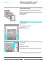
Description
1
Operator dialogue terminals
1
Magelis graphic stations
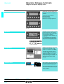
Front panel of graphic terminals
3
Graphic terminals with keypad, XBT F01/F02
XBT F01/F02 keypad terminals have the
1 following on the front panel:
1 A monochrome or colour screen (5.7", 9.5" or
10.4" depending on model).
2 2 x 4 or 2 x 5 (depending on model) dynamic
function keys with indicator lights.
3 A communication monitoring indicator light.
4 A keypad activity indicator light.
5 2 x 5 or 2 x 6 (depending on model) static
function keys with indicator lights and
changeable legends.
6 Twelve service keys with indicator lights.
7 Twelve alphanumeric keys (0…9, +/-, .)
associated with 3 alphabetical access keys
(A…Z).
2
2
4
5
5
6
1
7
Graphic terminals with touch-sensitive screen, XBT F03
XBT F03 touch-sensitive screen terminals
have the following on the front panel:
2
1 A touch-sensitive colour screen (5.7" or 10.4"
depending on model).
1 2 A communication monitoring indicator light.
3 A tactile feedback activity indicator light.
4 An alarm indicator light.
3
4
Graphic terminals with touch-sensitive screen, XBT FC
XBT FC touch-sensitive screen terminals
have the following on the front panel:
2
3
4
1
1 A touch-sensitive colour screen (5.7" or 10.4"
depending on model).
2 A communication monitoring indicator light.
3 A tactile feedback activity indicator light.
4 An alarm indicator light.
5 4, 8, 12 or 16 touch-sensitive keys (depending
on model).
5
Rear panel of graphic terminals XBT F
XBT F graphic terminals have the following on
the rear panel:
4
1 A plug-in screw terminal block for c 24 V power
supply and a connection for the alarm relay.
2 A 25-way female SUB-D connector for
connection to PLCs.
3 A 9-way male SUB-D connector for printer
connection and for transferring applications
from an FT2100 terminal or PC compatibles.
1 4 Two slots for PCMCIA card:
- one type II for application memory support,
- one type III for connection to the
communication architecture (bus or network).
5 An RJ 45 connector for connection to the
Ethernet TCP/IP network (depending on
model).
2
5
3
Characteristics:
page 1/26
References:
page 1/27
Dimensions:
page 1/47
1/25
Characteristics
1
Operator dialogue terminals
Magelis 5" graphic terminals
with keypad or touch-sensitive screen
Type of terminal
XBT F011
XBT F032
Environment
Conforming to standards
Product certifications
Temperature
Relative humidity
Degree of protection
Operation
Storage
Front panel
Rear panel
Shock resistance
Vibration
E.S.D.
Electromagnetic interference
Electrical interference
IEC 61131-2, IEC 61000-4-2 level 3, IEC 61000-4-3 and IEC 61000-4-4 level 3,
IEC 60068-2-6, IEC 60068-2-27, UL 508, CSA
e, UL class 1 Div 2. Group A, B, C, D-T4A, CSA class 1 Div 2. Group A, B, C, D-T4A
0…+ 45 °C
- 20…+ 60 °C
0…85% (without condensation)
IP 65, conforming to IEC 60529, Nema 4
IP 20, conforming to IEC 60529
Conforming to IEC 60068-2-27; semi-sinusoidal pulse 11 ms, 15 gn on the 3 axes
Conforming to IEC 60068-2-6; 10 to 57 Hz at 0.075 mm; 57 to 150 Hz, 1 gn for 3 hours per axis
Conforming to IEC 61000-4-2, level 3
Conforming to IEC 61000-4-3, 10 V/m
Conforming to IEC 61000-4-4, level 3
Mechanical characteristics
Mounting and fixing
Material
Keys
Screen protection
Front frame
Keypad
Enclosure
Dynamic keys
Static keys
Service keys
Alphanumeric keys
Flush mounted, fixed by spring clips (included), pressure mounted (on 1.6 to 6 mm thick panel)
10 spring clips
8 spring clips
Glass, 3 mm thick
Glass, 1.8 mm thick + polyester, 0.2 mm thick
Polyphenyl oxide, 10% glass fibre (PPO GFN1 SE1)
Anti-UV treated toughened polyester (Autoflex EB AG)
Polyphenyl oxide, 10% glass fibre (PPO GFN1 SE1)
8 (with LED)
–
10 (with LED and changeable legends)
–
12
–
12 + 3 for alphabetical access
–
Electrical characteristics
LCD screen
Optimum viewing angle
(degrees)
Power supply
Type
Definition
Luminescence (cd/m2 )
Vertical top
Vertical bottom
Vertical right
Vertical left
Voltage
Limits
Protection
Consumption
5.7" monochrome, back-lit with 16 levels of
5.7" STN 256 colours, back-lit with resistive
grey
matrix tactile feedback (8 x 6 cells)
320 x 240 pixels
130
180
20
35
20
60
30
50
30
50
c 24 V non isolated
18…30 V, including 5% maximum ripple, 1 ms maximum microbreaks
Against polarity inversion and overloads
35 W
Operating characteristics
Signalling
Operating system/Processor
Dynamic RAM memory
Application memory
Dialogue application
Maximum number of pages
Connections
Curves
Recipes
PLC/configuration PC
Printer
Bus or network
Real-time clock
Alarm relay
Connection
Power supply and alarm relay
PLC
Printer/configuration PC
References:
page 1/27
1/26
Dimensions:
page 1/47
1 communication monitoring LED and 1 keypad activity (or tactile feedback activity) LED and
11 LEDs associated with service and alphanumeric keys
Magelis/80386
2.5 Mb
On type II PCMCIA card: 8 Mb (included), or 16 Mb
50 to 450 application, alarm, help, form and recipe pages depending on the memory card used
(512 alarms max., 256 form max.)
16 real-time curves
5000 parameter values max., in a maximum of 125 recipe records
19200 baud RS 232 C/RS 422/485 isolated serial link, downloadable communication protocols
(see page 1/22 and page 1/40)
RS 232 C serial link
Slot for type III PCMCIA communication card depending on model, communication protocols
(see page 1/40)
Access to the PLC real-time clock
1 volt-free N/O contact, max. 0.5 A c/a 24 V
Plug-in terminal block, 5 screw terminals (pitched at 5.08 mm). Maximum clamping capacity:
1.5 mm2
25-way female SUB-D connector
9-way male SUB-D connector
1
References
1
Operator dialogue terminals
1
Magelis 5" graphic terminals
with keypad or touch-sensitive screen
521407
Graphic terminals with keypad
Downloadable exchange
protocol
See page 1/40
XBT F011p10
Supply
voltage
Monochrome 5.7"
Vc
24
Type III slot for
Reference
PCMCIA
communication card
Weight
No
XBT F011110
kg
1.800
Yes
XBT F011310
1.800
Type III slot for
PCMCIA
communication
card
No
Reference
XBT F032110
kg
1.600
Yes
XBT F032310
1.600
Graphic terminals with touch-sensitive screen
Downloadable
exchange protocol
See page 1/40
521406
Screen type and
size
Screen type and
size
Supply
voltage
Colour 5.7"
Vc
24
Weight
XBT F032p10
Separate parts
Description
Usage
Reference
Development software
Under Windows 98, 2000 or XP,
for downloading the application and protocols
See page 3/7
Connecting cables
Connection to PLCs, configuration terminals, etc.
See page 1/41
Weight
kg
–
–
Documentation
Description
Magelis user’s manual
Format
A5 bound
Reference
(1)
To order separately to the XBT L100pM CD-ROM XBT X000 pp
Weight
kg
0.700
(1) Add the following suffix to the reference: EN for English, FR for French, DE for German, ES for
Spanish, 1T for Italian.
Characteristics:
page 1/26
Dimensions:
page 1/47
1/27
1
Characteristics
1
Operator dialogue terminals
Magelis 5" or 10" graphic terminals
with touch-sensitive screen and keys
Type of terminal
XBT FC 022310
044510/044610
084510/0 84610
064510/064610
Environment
Conforming to standards
Product certifications
Temperature
Relative humidity
Degree of protection
Operation
Storage
Front panel
Rear panel
Shock resistance
Vibration
E.S.D.
Electromagnetic interference
Electrical interference
IEC 61131-2, IEC 61000-4-2 level 3, IEC 61000-4-3 and IEC 61000-4-4 level 3,
IEC 60068-2-6, IEC 60068-2-27, UL 508, CSA
e, UL, CSA
e, UL Class 1, Div 2. Group A, B, C, D-T4A, CSA Class 1, Div 2.
Group A, B, C, D-T4A
0…+ 45 °C
- 20…+ 60 °C
0…85% (without condensation)
IP 65, conforming to IEC 529, Nema 4
IP 20, conforming to IEC 529
Conforming to IEC 60068-2-27; semi-sinusoidal pulse 11 ms, 15 gn on the 3 axes
Conforming to IEC 60068-2-6; 10 to 57 Hz at 0.075 mm; 57 to 150 Hz, 1 gn for 3 hours per axis
Conforming to IEC 61000-4-2, level 3
Conforming to IEC 61000-4-3, 10 V/m
Conforming to IEC 61000-4-4, level 3
Mechanical characteristics
Mounting and fixing
Material
Screen protection
Front frame
Keypad
Enclosure
Touch-sensitive keys
Flush mounted, fixed by spring clips (included), pressure mounted (on 1.6 to 6 mm thick panel)
8 spring clips
10 spring clips
Glass, 1.8 mm thick + polyester, 0.2 mm thick
Polyphenyl oxide, 10% glass fibre (PPO GFN1 SE1)
Anti-UV treated toughened polyester (Autoflex EB AG)
Polyphenyl oxide, 10% glass fibre (PPO GFN1 SE1)
4 in 1 row
8 in 1 row
16 in 2 rows
12 in 2 columns
Electrical characteristics
LCD screen
Optimum viewing angle
(degrees)
Power supply
Type
Definition
Luminescence (cd/m2 )
Vertical top
Vertical bottom
Vertical right
Vertical left
Voltage
Limits
Protection
Consumption
5.7" STN
10.4" TFT
10.4" TFT
256 colours, back-lit with 256 colours with
256 colours with
resistive matrix tactile
resistive matrix
resistive matrix
feedback
tactile feedback
tactile feedback
(8 x 4 cells)
(13 x 8 cells)
(13 x 6 cells)
320 x 240 pixels
640 x 480 pixels
180
250
250
35
80
80
60
80
80
50
80
80
50
80
80
c 24 V non isolated
18…30 V, including 5% maximum ripple, 1 ms maximum microbreaks
Against polarity inversion and overloads
35 W
10.4" TFT
256 colours with
resistive matrix
tactile feedback
(9 x 10 cells)
250
80
80
80
80
Operating characteristics
Signalling
Operating system/Processor
Dynamic RAM memory
Application memory
Dialogue application
Connections
Maximum number of pages
Type of pages
Curves
Recipes
PLC/configuration PC
Printer
Bus or network
Real-time clock
Alarm relay
Connection
Power supply and alarm relay
PLC
Printer/configuration PC
References:
page 1/29
1/28
Dimensions:
page 1/47
1 communication monitoring LED, 1 keypad activity LED and 1 alarm LED
Magelis/80386
Magelis/Pentium
2.5 Mb
32 Mb
On type II PCMCIA card: 8 Mb (included), or 16 Mb
50 to 450
30 to 300
Application, alarm, help, form and recipe pages depending on the memory card used
(512 alarms max., 256 form max.)
16 real-time curves
5000 parameter values max., in a maximum of 125 recipe records
19200 baud
115200 baud RS 232 C/RS 422/485
RS 232 C/RS 422/485
isolated serial link, downloadable communication protocols
isolated serial link,
(see pages 1/22 and 1/40)
downloadable
communication protocols
(see pages 1/22 and 1/40)
RS 232 C serial link
Slot for type III PCMCIA communication card, communication protocols (see page 1/40).
Ethernet 10/100 TCP/IP RJ 45 connector depending on model
Access to the PLC
Built-in and backed-up
real-time clock
1 volt-free N/O contact, max. 0.5 A c/a 24 V
Plug-in terminal block, 5 screw terminals (pitched at 5.08 mm)
Maximum clamping capacity: 1.5 mm2
25-way female SUB-D connector
9-way male SUB-D connector
1
References
1
Operator dialogue terminals
1
Magelis 5" or 10" graphic terminals
with touch-sensitive screen and keys
811955
Graphic terminals with touch-sensitive screen and keys
Downloadable exchange
protocol
See page 1/40
802992
XBT FC022310
Screen
type and
size
Colour
5.7"
Supply
voltage
Vc
24
Number of
Ethernet 10/100 TCP/IP Reference
touchRJ 45 connector
sensitive keys
4
No
XBT FC022310
Colour
10.4"
24
8
Weight
kg
1.600
No
XBT FC044510
2.400
Yes
XBT FC044610
2.400
No
XBT FC084510
2.400
Yes
XBT FC084610
2.400
No
XBT FC064510
2.400
Yes
XBT FC064610
2.400
XBT FC044510
802994
16
XBT FC084510
802993
12
XBT FC064510
Separate parts
Description
Usage
Reference
Development software
Under Windows 98, 2000 or XP, for downloading
the application and protocols
See page 3/7
Connecting cables
Connection to PLCs, configuration terminals, etc.
See page 1/41
Format
Reference
(1)
XBT X000 pp
Weight
kg
–
–
Documentation
Description
Magelis user’s manual
A5 bound
To order separately to the XBT L100pM CD-ROM
Weight
kg
0.700
(1) Add the following suffix to the reference: EN for English, FR for French, DE for German, ES for
Spanish, 1T for Italian.
Characteristics:
page 1/28
Dimensions:
page 1/47
1/29
1
Characteristics
1
Operator dialogue terminals
Magelis 10" graphic terminals
with keypad or touch-sensitive screen
Type of terminal
XBT F023110/23310
XBT F024110
XBT F024510/24610
XBT F034110
XBT F034510/34610
Environment
Conforming to standards
IEC 61131-2, IEC 61000-4-2 level 3, IEC 61000-4-3 and IEC 61000-4-4 level 3, IEC 60068-2-6, IEC 60068-2-27,
UL 508, CSA
e, UL, CSA
e, UL Class 1, Div 2. Group A, B, C, D-T4A, CSA Class 1, Div 2. Group A, B, C, D-T4A
0…+ 45 °C
- 20…+ 60 °C
0…85% (without condensation)
IP 65, conforming to IEC 60529, Nema 4
IP 20, conforming to IEC 60529
Conforming to IEC 60068-2-27; semi-sinusoidal pulse 11 ms, 15 gn on the 3 axes
Conforming to IEC 60068-2-6; 10 to 57 Hz at 0.075 mm; 57 to 150 Hz, 1 gn for 3 hours per axis
Conforming to IEC 61000-4-2, level 3
Conforming to IEC 61000-4-3, 10 V/m
Conforming to IEC 61000-4-4, level 3
Product certifications
Temperature Operation
Storage
Relative humidity
Degree of
Front panel
protection
Rear panel
Shock resistance
Vibration
E.S.D.
Electromagnetic interference
Electrical interference
Mechanical characteristics
Mounting and fixing
Material
Keys
Screen protection
Front frame
Keypad
Enclosure
Dynamic keys
Static keys
Service keys
Alphanumeric keys
Flush mounted, fixed by spring clips (included), pressure mounted (on 1.6 to 6 mm thick panel)
12 spring clips
10 spring clips
Glass, 3 mm thick
Glass, 1.8 mm thick + polyester, 0.2 mm thick
Polyphenyl oxide, 10% glass fibre (PPO GFN1 SE1)
Anti-UV treated toughened polyester (Autoflex EB AG)
Polyphenyl oxide, 10% glass fibre (PPO GFN1 SE1)
10 (with LED)
–
12 (with LED and changeable legends)
–
12
–
12 + 3 for alphabetical access
–
Electrical characteristics
LCD screen
Type
Definition
Luminescence (cd/m2)
Optimum
Vertical top
viewing angle Vertical bottom
(degrees)
Vertical right
Vertical left
Power supply Voltage
Limits
Protection
Consumption
9.5" monochrome,
10.4" TFT 256 colours
back-lit with 16 levels
of grey
640 x 480 pixels
150
200
250
20
30
80
10
20
80
30
45
80
30
45
80
c 24 V non isolated
18…30 V, including 5% maximum ripple, 1 ms maximum microbreaks
Against polarity inversion and overloads
35 W
10.4" TFT 256 colours with resistive matrix
tactile feedback (13 x 10 cells)
200
30
20
45
45
250
80
80
80
80
Operating characteristics
Signalling
Operating system/Processor
Dynamic RAM memory
Application memory
Dialogue
Maximum number of
application
pages
Curves
Recipes
Connections PLC/configuration PC
Printer
Bus or network
Real-time clock
Alarm relay
Connection
References:
page 1/31
1/30
Power supply and alarm
relay
PLC
Printer/configuration PC
1 communication monitoring LED and 1 keypad activity (or tactile feedback activity) LED and 11 LEDs associated with
service and alphanumeric keys
Magelis/80386
Magelis/Pentium
Magelis/80386
Magelis/Pentium
2.5 Mb
2.5 Mb
32 Mb
2.5 Mb
32 Mb
On type II PCMCIA card: 8 Mb (included), or 16 Mb
30 to 300 application, alarm, help, form and recipe pages depending on the memory card used (512 alarms max., 256
form max.)
16 real-time curves
5000 parameter values max., in a maximum of 125 recipe records
19200 baud RS 232 C/RS 422/485
115200 baud
19200 baud
115200 baud
isolated serial link
RS 232 C/RS 422/485 RS 232 C/RS 422/485 RS 232 C/RS 422/485
isolated serial link
isolated serial link
isolated serial link
Downloadable communication protocols (see page 1/22 and page 1/40)
RS 232 C serial link
Depending on model: slot for type III PCMCIA communication card, communication protocols (see page 1/40), Ethernet
10/100 TCP/IP RJ 45 connector
Access to the PLC real-time clock
Built-in and backed-up Access to the PLC
Built-in and backed-up
real-time clock
1 volt-free N/O contact, max. 0.5 A c/a 24 V
Plug-in terminal block, 5 screw terminals (pitched at 5.08 mm). Maximum clamping capacity: 1.5 mm2
25-way female SUB-D connector
9-way male SUB-D connector
Dimensions:
page 1/47
1
References
1
Operator dialogue terminals
1
Magelis 10" graphic terminals
802963
with keypad or touch-sensitive screen
Graphic terminals with keypad
Downloadable
exchange protocol
See page 1/40
Screen
type and
size
Monochrome
9.5"
Supply
voltage
Vc
24
Type III slot for
PCMCIA
communication
card
No
Ethernet 10/100 Reference
TCP/IP RJ 45
connector
Weight
No
XBT F023110
kg
2.700
Yes
No
XBT F023310
2.700
No
No
XBT F024110
2.700
Yes
No
XBT F024510
2.700
Yes
Yes
XBT F024610
2.700
XBT F024 p10
Colour
10.4"
24
Graphic terminals with touch-sensitive screen
802964
Downloadable exchange
protocol
See page 1/40
Screen
type and
size
Colour
10.4"
XBT F034 p10
Supply
voltage
Vc
24
Type III slot for
PCMCIA
communication
card
No
Ethernet 10/100 Reference
TCP/IP RJ 45
connector
Weight
No
XBT F034110
kg
2.400
Yes
No
XBT F034510
2.400
Yes
Yes
XBT F034610
2.400
Separate parts
Description
Usage
Reference
Development software
Under Windows 98, 2000 or XP,
for downloading the application and protocols
See page 3/7
Connecting cables
Connection to PLCs, configuration terminals, etc.
See page 1/41
Weight
kg
–
–
Documentation
Description
Magelis user’s manual
Format
A5 bound
Reference
(1)
To order separately to the XBT L100pM CD-ROM XBT X000 pp
Weight
kg
0.700
(1) Add the following suffix to the reference: EN for English, FR for French, DE for German, ES for
Spanish, 1T for Italian.
Characteristics:
page 1/30
Dimensions:
page 1/47
1/31
1
General
1
Operator dialogue terminals
New Technology Magelis touch-sensitive
graphic terminals
Presentation
Optimum
The New Technology Magelis graphic
terminals XBT G are touch-sensitive
products with a wide choice of screen sizes
(5", 7", 10" and 12") as well as different
versions (monochrome, colour).
b An Optimum 5" monochrome terminal
for simple applications.
b A range comprising 9 multifunction
terminals from 5" to 12" for applications
requiring more functions.
Multifunction
5"
12"
10"
7"
5"
Operation
All Magelis XBT G model terminals feature the new information and communication
technologies:
b High level of communication (on-board Ethernet, multi-line).
b External support of data (“Compact Flash” card) for storage of production
information and saving of applications.
b Multimedia data with integrated management of image and sound.
Configuration
XBT G terminals can be configured using
the Vijeo Designer VJD SPUL software, in
a Windows environment.
The evolutive ergonomics of the
Vijeo Designer VJD SPUL software,
designed around several parameterable
windows, enables quick and simple
development of a project:
b Navigator,
b Object properties,
b Object listing,
b Library of animated graphic objects,
b Information,
b Report.
Communication
XBT G terminals communicate with PLCs
via one or two integrated serial links, using
Schneider Electric communication
protocols (Uni-Telway, Modbus).
The Magelis multifunction terminals can be
connected on Ethernet using Modbus
TCP/IP protocol.
Micro
Twido
Uni-Telway / Modbus
XBT G
Ethernet TCP/IP
Premium
XBT G
XBT G
Micro
Modbus Plus
Quantum
Momentum
ATV 58
Selection guide:
page 1/5
1/32
Architecture:
page 1/6
Characteristics:
pages 1/36 and 1/38
References:
pages 1/37 and 1/39
Dimensions:
page 1/47
1
Functions,
description
Operator dialogue terminals
1
1
New Technology Magelis touch-sensitive
graphic terminals
Functions
XBT G graphic terminals offer the following functions:
b Display of animated synoptic screens with 8 types of animation:
- pressing touch-sensitive zone,
- changing of colour,
- filling,
- movement,
- rotation,
- size,
- visibility,
- value display.
b Control, modification of numeric and alphanumeric variables.
b Display of date and time.
b Real-time and trending curves with log.
b Alarm display, alarm log and management of alarm groups.
b Multiwindow management.
b Pages can be called up by the user.
b Multilingual application management.
b Data processing via Java script.
b Application and log support in the “Compact Flash” format external application
memory card.
b Management of sound messages.
Operating structure of graphic terminals
The following diagrams indicate the equipment that can be connected to XBT G
terminals according to their operating mode.
Editing mode
Ethernet network (1)
PC with Vijeo Designer software installed
XBT G
Connecting cable
XBT ZG 915
“Compact Flash” card
XBT ZGM16/32 (2)
Operating mode
Ethernet network (1)
Connecting cable
TSX PCX 1031
Twido
Connecting cable
XBT G
“Compact Flash”
card
XBT ZGM16/32 (2)
XBT Z968
Loudspeaker (3)
Premium
(1) Connection not possible for XBT G2110, G2120, G2220 and G4320.
(2) Not available for XBT G2110.
(3) Not available for XBT G2110, G2120, G2130, G2220, G2330 and G4320.
1/33
1
Description
1
Operator dialogue terminals
1
New Technology Magelis touch-sensitive
graphic terminals
Description
Optimum graphic terminal XBT G2110
It has the following on the front panel:
1 A touch-sensitive message display screen (blue
mode 5.7" monochrome),
2 A back-lighting control light.
1
2
And on the rear panel:
1 A screw terminal block for c 24 V power supply.
2 A 25-way female SUB-D connector for RS 232 C
or RS 485 serial link to PLCs (COM 1).
1
3 A connector for application transfer cable.
2
3
Multifunction graphic terminals XBT G2120, G2220, G2130 and G2330
They have the following on the front panel:
1 A touch-sensitive message display screen
(5.7" monochrome or colour),
2 A back-lighting control light.
1
2
And on the rear panel:
2
6
3
1
4
7
8
5
Characteristics:
pages 1/36 and 1/38
1/34
References:
pages 1/37 and 1/39
Dimensions:
page 1/47
1 A screw terminal block for c 24 V power supply.
2 An extension unit interface (for future use).
3 A 25-way female SUB-D connector for RS 232 C
or RS 485 serial link to PLCs (COM 1).
4 A connector for application transfer cable.
5 A slot for “Compact Flash” card, with cover.
On XBT G2130 and G2330 only
6 A 9-way SUB-D serial extension connector
(COM 2).
7 A centronics type printer connector (for future
use).
8 An RJ 45 type connector for Ethernet (10 BaseT)
link.
Description
1
Operator dialogue terminals
1
New Technology Magelis touch-sensitive
graphic terminals
Description
Multifunction graphic terminals XBT G4320, G4330
1
They have the following on the front panel:
1
1 A touch-sensitive message display screen
(7.4" colour),
2 A back-lighting control light.
2
And on the rear panel:
1 A screw terminal block for c 24 V power supply.
8 2 An extension unit interface (for future use).
3 A 25-way female SUB-D connector for RS 232 C
6
or RS 485 serial link to PLCs (COM 1).
4 A connector for application transfer cable.
5 A centronics type printer connector (for future
use).
5 6 A slot for “Compact Flash” card, with cover.
2
1
9
3
7
On XBT G4330 only
7 A 9-way SUB-D serial extension connector
(COM 2) (for future use).
8 An RJ 45 type connector for Ethernet (10baseT)
link.
9 An input/output terminal block for loudspeaker
connection.
4
Multifunction graphic terminals XBT G5230, G5330 and G6330
They have the following on the front panel:
1 A touch-sensitive message display screen
(10.4" or 12.1" colour),
1 2 A back-lighting control light.
2
And on the rear panel:
1
6 8 7
3
9
5 4
1 A screw terminal block for c 24 V power supply.
2 Two extension unit interfaces, 1 and 2 (only one
2
on XBT G5230) (for future use).
3 A 25-way female SUB-D connector for RS 232 C
or RS 485 serial link to PLCs (COM 1).
4 A connector for application transfer cable.
5 A 9-way SUB-D serial extension connector
(COM 2) (for future use).
6 A centronics type printer connector (for future
use).
7 An RJ 45 type connector for Ethernet (10baseT)
link.
8 A slot for “Compact Flash” card, with cover.
9 An input/output terminal block for loudspeaker
connection.
1/35
Characteristics
1
Operator dialogue terminals
New Technology Magelis touch-sensitive
graphic terminals, 5" screen
Type of terminal
XBT G2110
XBT G2120
XBT G2130
XBT G2220
XBT G2330
Environment
Conforming to standards
Product certifications
Temperature
EN 61131-2, IEC 60068-2-6, IEC 60068-2-27, UL 508, CSA C22-2 n°14
e, UL, CSA, Class 1 Div 2 T4A (UL and CSA)
0…50 °C
- 20…+ 60 °C
0…85% (without
0…90% (without condensation)
condensation)
< 2000 m
IP 65 conforming to IEC 60529, Nema 4X
IP 20 conforming to IEC 60529
Conforming to IEC 60068-2-27; semi-sinusoidal pulse 11 ms, 15 gn on the 3 axes
Conforming to IEC 60068-2-6; 10 to 57 Hz at 0.075 mm; 57 to 150 Hz, 1 gn for 3 hours per axis
Conforming to IEC 61000-4-2, level 3
Conforming to IEC 61000-4-3, 10 V/m
Conforming to IEC 61000-4-4, level 3
Operation
Storage
Relative humidity
Altitude
Degree of protection
Front panel
Rear panel
Shock resistance
Vibration
E.S.D.
Electromagnetic interference
Electrical interference
Mechanical characteristics
Mounting and fixing
Material
Flush mounted, fixed by 6 screw clamps (included), on 1.6…10 mm thick panel
Polycarbonate /
Aluminium
polyethylene
terephthalate
Enclosure
Electrical characteristics
Power supply
c 24 V
c 20.4…27.6 V
y 2 ms
y 30 A
20 W
Voltage
Limits
Voltage cut
Inrush current
Consumption
c 19.2…28.8 V
y 10 ms
22 W
Operating characteristics
LCD screen
Type
Colour
Back-lit monochrome STN
Blue and white
Black and white
Definition
Size (width x height in mm)
Touch-sensitive zone
Back-lighting (service life)
320 x 240 pixels (QVGA)
5.7" (115.2 x 86.4)
Resistive film, 16 x 12 cells
25,000 hours at
50,000 hours at 25 °C for continual usage
25 °C
–
4 levels via tactile feedback
8 levels via tactile feedback
–
8 levels via
–
tactile
feedback
ASCII, Japanese (ANK, Kanji), Chinese (simplified Chinese), Taiwanese (traditional Chinese),
Korean
Limited by the internal Flash memory capacity or “Compact Flash” card memory capacity
1 LED: green for normal operation, orange if back-lighting faulty
Magelis/CPU 100 MHz RISC
4 Mb Flash EPROM
6 Mb Flash EPROM 4 Mb Flash
6 Mb Flash EPROM
EPROM
128 Kb SRAM (lithium batteries)
256 Kb SRAM (lithium batteries)
Modbus, Uni-Telway
Modbus,
Modbus,
Modbus,
Uni-Telway,
Uni-Telway
Uni-Telway,
Modbus TCP/IP
Modbus TCP/IP
Built-in real-time clock
Screw terminal block: 3 terminals, tightening torque 0.5 Nm
25-way SUB-D connector (RS 232 C/RS 485 serial link)
–
9-way SUB-D
–
9-way SUB-D
connector (RS 232
connector (RS 232
C serial link)
C serial link)
–
For future use
–
For future use
–
Ethernet,
–
Ethernet,
IEEE 802.3
IEEE 802.3
10 BaseT, RJ 45
10 BaseT, RJ 45
Via Mini-DIN socket
–
For future use
–
–
1 slot for “Compact Flash” card
–
Settings
Brightness
Contrast
Character fonts
Dialogue application
Max. number of pages
Signalling
Operating system/Processor
Memory
Application
Back-up of data
Protocols
Real-time clock
Connection
Power supply
Com 1 serial port
Com 2 serial port
Printer port
Network (protocol)
Application downloading
Extension 1
Extension 2
“Compact Flash” card
Input/output terminal block
Presentation:
page 1/32
1/36
References:
page 1/37
Dimensions:
page 1/47
Colour STN
64 colours
Colour TFT
256 colours, 64 if
flashing
1
References
1
Operator dialogue terminals
1
New Technology Magelis touch-sensitive
graphic terminals, 5" screen
Graphic terminals (1)
Type of screen
On-board
Ethernet
Number
of serial
ports
Application “Compact Flash”
memory
card slot
capacity
Reference
Weight
kg
No
1
4 Mb
No
XBT G2110
1.600
No
1
4 Mb
Yes
XBT G2120
1.400
Yes
2
6 Mb
Yes
XBT G2130
1.400
Colour STN
No
1
4 Mb
Yes
XBT G2220
1.400
Colour TFT
Yes
2
6 Mb
Yes
XBT G2330
1.400
Compatibility
Size
Reference
XBT G2120/G2130/G2220/G2330
16 Mb
XBT ZGM16
Weight
kg
0.050
32 Mb
XBT ZGM32
0.050
PC with PCMCIA card reader
XBT ZGADT
0.050
XBT G2110
XBT ZG31
0.200
XBT G2120/G2130/G2220/G2330
XBT ZG32
0.200
For use with
Reference
XBT G2110
XBT ZG21
Weight
kg
0.030
XBT G2120/G2130/G2220/G2330
XBT ZG22
0.030
Back-lighting lamp
XBT G2120/G2130/G2220
XBT ZG12
0.150
Fixing kit: 4 clamps and
screws (max. tightening
torque: 0.5 Nm)
Included with all XBT G
terminals
Extension connector
protection
All XBT G
XBT ZGSET
0.100
XBT G2120/G2130/G2220/G2330
XBT ZGCOV
0.030
Optimum 5.7"
XBT G2110
Monochrome
blue mode STN
Multifunction 5.7"
Monochrome
black and white STN
XBT G2120
Separate parts
Description
“Compact Flash”
memory cards
XBT ZGM16
Adaptor for “Compact
Flash” cards
Protective sheets
Spare parts
Description
Seals
Connection cables and accessories (2)
Description
Transfer cable
Cable adaptor
Included with all XBT G
terminals
PLC connection cable
Usage
From
PC
To
All XBT G
Type of
connector
Physical Reference
link
TTL
XBT ZG915
0.250
RS 485
XBT ZG999
0.030
RS 232
TSX PCX 1031
0.250
All XBT G
Cables
XBT Z9 ppp
SUB-D 9 /
Mini-DIN
SUB-D 25 /
SUB-D 25
Twido, Nano,
Micro, Premium
All XBT G
(COM 2)
Mini-DIN /
SUB-D 9
Weight
kg
Documentation
Description
Composition
Support
Reference
(3)
VJD USE 000V10 p
Weight
kg
–
Technical documentation 2 multilingual volumes:
Paper
set
Vijeo Designer educational software, (also included in pdf
Setting-up Terminals XBT G
format on software
CD-ROM)
(1) Supplied with cable adaptor for connection to PLCs, service instructions and fixing kit.
Configuration software, separate parts and connection accessories, see page 3/7.
(2) For other connection cables, see pages 1/40 and 1/41.
(3) Add the following suffix to the reference: E for English, F for French, G for German, 1T for
Italian, S for Spanish.
1/37
1
Characteristics
1
Operator dialogue terminals
New Technology Magelis touch-sensitive
graphic terminals, 7", 10" or 12" screen
Type of terminal
XBT G4320
XBT G4330
XBT G5230
XBT G5330
XBT G6330
Environment
Conforming to standards
Product certifications
Temperature
Operation
Storage
Relative humidity
Altitude
Degree of protection
Front panel
Rear panel
Shock resistance
Vibration
E.S.D.
Electromagnetic interference
Electrical interference
EN 61131-2, IEC 60068-2-6, IEC 60068-2-27, UL 508, CSA C22-2 n°14
e, UL, CSA, Class 1 Div 2 T4A (UL and CSA)
0…50 °C
- 20…+ 60 °C
10…90% (without condensation)
< 2000 m
IP 65 conforming to IEC 60529, Nema 4X
IP 20 conforming to IEC 60529
Conforming to IEC 60068-2-27; semi-sinusoidal pulse 11 ms, 15 gn on the 3 axes
Conforming to IEC 60068-2-6; 10 to 57 Hz at 0.075 mm; 57 to 150 Hz, 1 gn for 3 hours per axis
Conforming to IEC 61000-4-2, level 3
Conforming to IEC 61000-4-3, 10 V/m
Conforming to IEC 61000-4-4, level 3
Mechanical characteristics
Mounting and fixing
Material
Flush mounted, fixed by 6 screw clamps (included), on 1.6…10 mm thick panel
Polycarbonate / polyethylene terephthalate
Enclosure
Electrical characteristics
Power supply
c 24 V
c 19.2…28.8 V
y 10 ms
Voltage
Limits
Voltage cut
y 30 A
28 W
50 W
Type
Colour TFT
Colour STN
Colour TFT
Colour
256 colours, 64 if flashing
64 colours
256 colours, 64 if flashing
Definition
640 x 480 pixels (VGA)
Size (width x height in mm)
7.4" (149.8 x 112.3)
Touch-sensitive zone
Resistive film, 32 x 24 cells
Back-lighting (service life)
50,000 hours at 25 °C for continual usage
Settings
4 levels via tactile feedback
–
Inrush current
Consumption
Operating characteristics
LCD screen
Brightness
Contrast
Character fonts
Dialogue application
Max. number of pages
10.4" (211.2 x 158.4)
8 levels via tactile –
feedback
ASCII, Japanese (ANK, Kanji), Chinese (simplified Chinese), Taiwanese (traditional Chinese),
Korean
Limited by the internal Flash memory capacity or “Compact Flash” card memory capacity
Signalling
Operating system/Processor
1 LED: green for normal operation, orange if back-lighting faulty
Magelis/CPU 100 MHz RISC
Memory
6 Mb Flash
8 Mb Flash EPROM
EPROM
128 Kb SRAM
512 Kb SRAM (lithium batteries)
(lithium batteries)
Modbus,
Modbus, Uni-Telway, Modbus TCP/IP
Uni-Telway
Built-in real-time clock
Screw terminal block: 3 terminals, tightening torque 0.5 Nm
25-way SUB-D connector (RS 232 C/RS 485 serial link)
–
9-way SUB-D connector (RS 232 C serial link)
For future use
–
Ethernet, IEEE 802.3 10 BaseT, RJ 45
Via Mini-DIN socket
For future use
–
For future use
1 slot for “Compact Flash” card
–
Connector for loudspeaker
Application
Back-up of data
Protocols
Real-time clock
Connection
Presentation:
page 1/32
1/38
Power supply
Com 1 serial port
Com 2 serial port
Printer port
Network (protocol)
Application downloading
Extension 1
Extension 2
“Compact Flash” card
Inputs/outputs
References:
page 1/39
800 x 600 pixels
(SVGA)
12.1"
(246 x 184.5)
Resistive film,
40 x 30 cells
Dimensions:
page 1/47
1
References
1
Operator dialogue terminals
1
New Technology Magelis touch-sensitive
graphic terminals, 7", 10" or 12" screen
Graphic terminals (1)
Type of screen
On-board
Ethernet
Number of
serial ports
Application
memory
capacity
“Compact Flash”
card slot
Reference
Weight
kg
No
1
6 Mb
Yes
XBT G4320
2.600
Yes
2
8 Mb
Yes
XBT G4330
2.600
Colour STN
Yes
2
8 Mb
Yes
XBT G5230
4.200
Colour TFT
Yes
2
8 Mb
Yes
XBT G5330
4.200
Yes
2
8 Mb
Yes
XBT G6330
4.200
Multifunction 7.4"
Colour TFT
XBT G4320
Multifunction 10.4"
Multifunction 12.1"
Colour TFT
XBT G5230
Separate parts
Description
Compatibility
Size
Reference
XBT G4320/G4330/G5230/G5330/
G6330
16 Mb
XBT ZGM16
Weight
kg
0.050
32 Mb
XBT ZGM32
0.050
PC with PCMCIA card reader
XBT ZGADT
0.050
XBT G4320/G4330
XBT ZG34
0.200
XBT G5230/G5330/G6330
XBT ZG36
0.200
For use with
Reference
Seals
XBT G4320/G4330
XBT G5230/G5330/G6330
XBT ZG24
XBT ZG26
Weight
kg
0.030
0.030
Back-lighting lamp
XBT G4320/G4330
XBT G5230
XBT G5330
XBT G6330
XBT ZG14
XBT ZG13
XBT ZG15
XBT ZG16
0.200
0.100
0.200
0.200
Fixing kit: 4 clamps and
screws (max. tightening
torque: 0.5 Nm)
Included with all XBT G
terminals
Extension connector
protection
All XBT G
XBT ZGSET
0.100
XBT G4320/G4330/G5230/G5330/G6330
XBT ZGCOV
0.030
“Compact Flash”
memory cards
Adaptor for “Compact
Flash” cards
Protective sheets
XBT G6330
Spare parts
Description
XBT ZGM16
Connection cables and accessories (2)
Description
Transfer cable
Cable adaptor
Included with all XBT G
terminals
PLC connection cable
Usage
From
PC
All XBT G
Twido, Nano,
Micro, Premium
To
All XBT G
Type of
connector
SUB-D 9 /
Mini-DIN
Cables XBT Z9 ppp SUB-D 25 /
SUB-D 25
All XBT G
(COM 2)
Mini-DIN /
SUB-D 9
Physical Reference
link
Weight
kg
TTL
XBT ZG915
0.250
RS 485
XBT ZG999
0.030
RS 232
TSX PCX 1031
0.250
Documentation
Description
Composition
Support
Reference
(3)
VJD USE 000V10 p
Weight
kg
–
Paper
Technical documentation 2 multilingual volumes:
set
Vijeo Designer educational software, (also included in pdf
format on software
Setting-up Terminals XBT G
CD-ROM)
(1) Supplied with cable adaptor for connection to PLCs, service instructions and fixing kit.
Configuration software, separate parts and connection accessories, see page 3/7.
(2) For other connection cables, see pages 1/40 and 1/41.
(3) Add the following suffix to the reference: E for English, F for French, G for German, 1T for
Italian, S for Spanish.
1/39
1
References
1
Operator dialogue terminals
1
Separate parts
Downloadable Third party protocols
Description
Selection of Third party downloadable
protocols for PLCs
Support
Reference
CD-ROM
XBT L1PROT
Weight
kg
0.100
Content details
PLC brand
Compatibility
XBT N
–
–
–
–
Protocol name
XBT F
b
b
b
b
DF1/DH485
SNPX
Sysmacway
AS511, 3964R, PPI, MPI
Compatibility
Support
Reference
AS-Interface
XBT H/P/HM
Module pitched at 22.5 XBT ZA994
Modbus Plus
XBT F
Type III PCMCIA
TSX MBP100
0.110
Fipio
XBT F
Type III PCMCIA
TSX FPP 10
0.110
Fipway
XBT F
Type III PCMCIA
TSX FPP 20
0.110
Allen Bradley
GE Fanuc
Omron
Siemens
XBT H/P/E/HM/PM
b
b
b
b
Communication on bus and networks
Type of protocol
Weight
kg
0.300
Type II PCMCIA memory card
802970
Size
Compatibility
Approximate number of pages
XBT F01
XBT F02/F03
Reference
XBT F (1)
720
480
XBT MEM16
Compatibility
Sold in lots of
Unit reference
XBT H02p010
1
XBL YH4
Weight
kg
0.100
XBT P01p010
1
XBL YP8
0.100
XBT P02pp10
1
XBL YP12
0.100
XBT E
1
XBL YE24
0.100
XBT HM
1
XBL YHM4
0.100
XBT F01
1
XBL YF10
0.100
XBT F02
1
XBL YF12
0.100
Desk holder
XBT F
2
XBT Z3001
0.200
Spring clips
XBT N/HM/PM/F
12
XBT Z3002
0.200
XBT H/P/E
10
XBT Z3003
0.200
XBT N/H/P/E/HM/PM/F
10
XBT Z3004
0.200
Compatibility
Connection
Reference
RS 232C PC link
(2.5 m)
XBT N401/NU400/H/P/E/HM/PM/F
XBT N200/N400
9-way (male)
9-way + Mini-DIN
XBT Z915
XBT Z945
Weight
kg
0.200
0.200
Between XBT Z915 cable
and XBT F terminal
Serial printer
XBT F
9/25-way
XBT Z962
0.100
Any XBT with printer port
9/25-way
XBT Z936
0.200
16 Mb
Weight
kg
0.100
XBT MEM16
Accessories
Type
Sheets of changeable
legends
Power supply connector
Connection to PCs and printers
Usage
(1) PCMCIA card included with the XBT F terminal.
1/40
References (continued)
1
Operator dialogue terminals
1
Separate parts
Cables for connecting Magelis terminals to PLCs, motor starters and drives
Type of PLC to be
connected
Type of connector
Physical link Protocol
Length
m
Reference
Weight
kg
Direct connection of XBT N401/H/P/E/HM/PM/F/G terminals to Telemecanique PLCs
Twido, Modicon Nano,
Modicon TSX Micro,
Modicon Premium
8-way female mini-DIN
terminal port
RS 485
Uni-Telway
(V1/V2) and
Modbus
Modicon Premium
with TSX SCY 2160p
Modicon Quantum
TSX 17
25-way female SUB-D
RS 485
9-way male SUB-D
15-way female SUB-D
terminal port
15-way female SUB-D
RS 232
RS 485
TSX LES 64/74 cable
connector
25-way female SUB-D
RS 485
9-way male SUB-D
RJ 45 male jack
RS 232
RS 232
Uni-Telway
(V1/V2)
Modbus
Uni-Telway
(V1)
Uni-Telway
(V1)
Uni-Telway
(V1)
Uni-Telway
(V1)
Modbus
Modbus
RJ 45 male jack
9-way male SUB-D
RJ 45 male jack
RS 232
RS 232
RS 232
Modbus
KS
KS
TSX 17
with TSX SCG 1161
TSX Series 7 model 40
on processor
TSX Series 7 model 40
with TSX SCM 21p6
984
Modicon Micro
Modicon Momentum M1
(Port 1)
Modbus/ Ethernet gateway
AEG ALU (1)
AEG Micro (1)
RS 485
RS 485
2.5
5
2.5 +
elbowed
connector
2.5
XBT Z968
XBT Z9681
XBT Z9680
0.180
0.340
0.170
XBT Z918
0.230
2.5
5
XBT Z9710
XBT Z958
0.210
0.240
5
XBT Z928
0.240
5
XBT Z948
0.230
5
XBT Z918
0.230
2.5
2.5
XBT Z9710
XBT Z9711
0.210
0.210
2.5
2.5
2.5
XBT Z9713
XBT Z9712
XBT Z9711
0.210
0.210
0.210
Direct connection of XBT N401/NU400/H/P/E/HM/PM/F terminals to Telemecanique motor starters and
drives
LT6
25-way female SUB-D
RS 232
Modbus
2.5
XBT 9701
0.210
TeSys model U,
ATV 28/38/58 and
ATS 48 drives
RJ 45
RS 485
Modbus
2.5
XBT Z938
0.210
2.5
2.5
2.5
2.5
2.5
2.5
2.5
3.7
2.5
2.5
2.5
XBT Z9730
XBT Z9720
XBT Z9731
XBT Z9732
XBT Z9750
XBT Z9740
XBT Z9741
XBT Z979
XBT Z9721
XBT Z9720
XBT Z939 +
XBT Z909 (2) (3)
0.210
0.210
0.210
–
0.210
0.210
0.210
0.500
0.210
0.210
0.215
Length
m
2.5
1.8
Reference
XBT Z9702
XBT Z908
Weight
kg
0.200
0.240
15-way female SUB-D
2.5
5
1.8
XBT Z968
XBT Z9681
XBT Z908
0.180
0.340
0.240
RJ 45
2.5
XBT Z938
0.210
Direct connection of XBT H/P/E/HM/PM/F terminals to third party PLCs
Allen Bradley SLC5
Allen Bradley PLC5
Allen Bradley Micro-logix
9-way male SUB-D
25-way female SUB-D
Micro-logix 1000
RS 232
RS 232
RS 232
GE Fanuc Series 90
Omron CQM1, CVM1
Omron CVM1
Siemens S7
Siemens S7 (PG)
Siemens S5 CP525
Siemens S5 (PG)
15-way male SUB-D
9-way male SUB-D
9-way male SUB-D
9-way male SUB-D
9-way male SUB-D
25-way female SUB-D
15-way female SUB-D
RS 232/422
RS 232
RS 422
RS 232
RS 485
RS 232
BC/RS 232
converter
DF1
DF1
DF1
DH485
SNPX
Sysmacway
Sysmacway
MPI
PPI
3964(R)
AS511
Bus and network connection
Type of bus/network
AS-Interface
Uni-Telway
Modbus
Ethernet
Fipio/Fipway/Modbus Plus
Tap-off unit
Type of connector
XBT ZA994
–
TSX SCA 62 subscriber 15-way female SUB-D
socket
TSX P ACC 01 cable
8-way female mini-DIN
connector
TSX SCA62 subscriber
socket
Modbus LU9 GC3
8-port splitter box
499 NEHppppp
499 NESppppp
RJ 45
2
490 NTW 000 02
5
490 NTW 000 05
12
490 NTW 000 12
40
490 NTW 000 40
80
490 NTW 000 80
–
–
–
See page 1/43
(1) All Magelis display units and terminals except XBT N.
(2) Order 2 cables: XBT Z939 (operational voltage 5 to 20 Volts) and XBT Z909.
(3) The BC/RS232 converter XBT Z939 is only for use with Siemens PLCs.
–
–
–
–
–
1/41
1
Connections
1
Operator dialogue terminals
1
Magelis graphic terminals
Connection to Fipio bus
XBT F
3
4
5
2
3
4
1
6
2
2
5
7
Micro
Premium
(bus manager)
1 TSX FP CA p00: shielded twisted pair trunk cable, 150 Ω (diameter 8 mm) for
normal environment or inside buildings,
or
TSX FP CR p00: shielded twisted pair trunk cable, 150 Ω (diameter 8 mm) for
harsh environment or outside buildings.
2 TSX FP ACC 4: IP 65 junction box.
3 TSX FPP 10: PCMCIA card, Fipio agent function.
4 TSX FP CG 0p0: tap-off connecting cable for PCMCIA TSX FPP 10/20 module
card.
5 TSX FP ACC 7: line terminator to be placed at each segment end.
6 TSX FP CC p00: tap-off cable, shielded twisted pair, 150 Ω (diameter 8 mm) for
normal environment or inside buildings.
7 TSX FP ACC 2/12: 9-way female SUB-D type connector.
Connection to Fipway network
XBT F
3
4
5
2
3
Micro
4
1
2
3
4
2
5
Premium
1 TSX FP CA p00: shielded twisted pair trunk cable, 150 Ω (diameter 8 mm) for
normal environment or inside buildings,
or
TSX FP CR p00: shielded twisted pair trunk cable, 150 Ω (diameter 8 mm) for
harsh environment or outside buildings.
2 TSX FP ACC 4: IP 65 junction box.
3 TSX FPP 20: PCMCIA card, Fipway.
4 TSX FP CG 0p0: tap-off connecting cable for PCMCIA TSX FPP 10/20 module
card.
5 TSX FP ACC 7: line terminator to be placed at each segment end.
References:
page 1/43
1/42
References
1
Operator dialogue terminals
1
Magelis graphic terminals
Fipway network/Fipio bus connection cables and accessories (1)
802988
Description
Type
Condition of use
Fipio on XBT F
Length
m
–
Fipio PCMCIA card
Agent function
Fipway PCMCIA card
Trunk cables
Reference
TSX FPP 10
Weight
kg
0.110
–
Fipway on XBT F
–
TSX FPP 20
0.110
8 mm, shielded
twisted pair, 150 Ω
In normal environment (2) 100
and inside buildings
TSX FP CA 100
5.680
200
TSX FP CA 200
10.920
500
TSX FP CA 500
30.000
In harsh environment (3) 100
and outside buildings or in
a daisy chain (3)
200
TSX FP CR 100
7.680
TSX FP CR 200
14.920
500
TSX FP CR 500
40.000
TSX FPP p0
521442
8 mm, shielded
twisted pair, 150 Ω
521441
TSX FP ACC 4
Dust and damp-proof
junction box
Zamac
IP 65
Trunk cable tap-off
–
TSX FP ACC 4
0.660
Line terminators
(sold in lots of 2)
–
–
–
TSX FP ACC 7
0.020
Female connectors,
9-way SUB-D type
Zamac
–
–
TSX FP ACC 2
0.080
Black polycarbonate
IP 20
–
–
TSX FP ACC 12
0.040
Length
m
Reference
1
TSX FP CG 010
0.210
3
TSX FP CG 030
0.410
100
TSX FP CC 100
5.680
200
TSX FP CC 200
10.920
500
TSX FP CC 500
30.000
TSX FP ACC 7
Tap-off connection cables
802987
Description
Cables for PCMCIA card
Tap-off cables
TSX FP CG 0p0
Usage
From
TSX FPP 10/20
card
TSX FP ACC 2
or
TSX FP ACC 12
connector
To
TSX FP ACC 4 junction
box
TSX FP ACC 4 junction
box
Weight
kg
(1) The characteristics and performance of the Fipio bus or Fipway network are dependent on the above TSX FP accessories
being used.
(2) Normal environment:
b without special environmental constraint,
b operating temperature between + 5 °C and + 60 °C,
b fixed installations.
(3) Harsh environment:
b resistance to hydrocarbons, industrial oils, detergents and solder chips,
b relative humidity up to 100%,
b saline environment,
b extreme variations in temperature,
b operating temperature between - 10 °C and + 70 °C.
b mobile installations, cables tested in accordance with the standard VDE 472 part 603/H:
v for use in a daisy chain, minimum radius of curvature of cable = 75 mm min.,
v for use on a gantry, providing certain installation conditions are met (acceleration, speed, length, etc.), please consult your
Regional Sales Office,
b not suitable for use on robots or multi-axial applications.
Connections:
page 1/42
1/43
1
Connections
1
Operator dialogue terminals
1
Magelis graphic terminals
Connection to Modbus Plus network
1
XBT F
T XBT F
5
5
10
5
Modbus Plus
5
3
10
11
1
1
Micro
5
9
10
Premium
5
6
9
Quantum
5
4
9
7
2
7
7
12
8
Momentum
1
1
2
3
4
5
6
10
1
TSX MBP 100: Modbus Plus PCMCIA card for Magelis terminals and Micro or Premium PLCs.
170 PNT 110 20: communication module for Momentum I/O base units.
490 NAA 271 0p: shielded twisted pair trunk cable with shielding drain (free wires at each end). Lengths: 30, 150, 300, 450 or 1500 m.
170 MCI 020 pp/021 20: tap-off cable fitted with an RJ45 type connector at each end. Lengths: 0.25, 0.75, 3 or 10 m.
990 NAD 230 00: IP 20 junction box (integrates the line terminator).
990 NAD 230 10: IP 65 zamac junction box, provides trunk cable tap-off for connection of equipment (screw terminal connections). In
addition, it incorporates an RJ45 type connector for connection of a programming and maintenance terminal.
7 170 XTS 020 00: IP 20 T-junction, provides tap-off for the Modbus Plus cable (cable fitted with an RJ45 type connector at each end). It has
a 9-way female SUB-D type connector for connection of the equipment.
8 TSX MBP CE 030/060: tap-off cable for Modbus Plus PCMCIA card, fitted with a miniature 20-way connector on the PCMCIA side and with
free wires on the 990 NAD 230 00/10 junction box side. Length: 3 or 6 m.
9 990 NAD 211 10/30: tap-off cable fitted with a 9-way female SUB-D type connector on the equipment side and with free wires on the
990 NAD 230 00/10 junction box side. Length: 2.4 or 6 m.
10 TSX MBP CE 002: tap-off cable for Modbus Plus PCMCIA card, fitted with a miniature 20-way connector on the PCMCIA side and a 9-way
male SUB-D type connector on the network side. Can be used as an extension for cable 990 NAD 211 10/30. Length: 0.2 m.
11 AS MBKT 185: set of 2 line terminators (impedance matching) to be placed at each segment end. The line terminators AS MBKT 185 are
used directly at the cable end (without junction box or T-junction).
990 NAD 230 11: set of 2 line terminators (impedance matching) for IP 65 junction box 990 NAD 230 10, to be placed at each segment end.
12 170 XTS 021 00: set of 2 line terminators (impedance matching) for T-junction 170 XTS 020 00, to be placed at each segment end.
References:
page 1/45
1/44
References
1
Operator dialogue terminals
1
Magelis graphic terminals
References
Description
Modbus Plus
PCMCIA card
TSX MBP 100
Description
Communication module
for Momentum I/O base
units
170 PNT 110 20
For use with
Item
Description
Magelis terminals XBT F
Micro and Premium PLCs
1
1 type III
PCMCIA
card
Connection
Item
Modbus Plus network on Momentum I/O
base units
2
Reference
(1)
TSX MBP 100
Weight
kg
0.110
Reference
(1)
170 PNT 110 20
Weight
kg
0.110
Reference
(1)
990 NAD 230 00
Weight
kg
0.230
990 NAD 230 10
0.650
170 XTS 020 00
0.260
AS MBKT 185
0.260
Connection accessories (2)
Description
Modbus Plus junction
boxes
Line terminators
(sold in lots of 2)
Cabling tool
Usage
Item
IP 20 junction box for tap-off connection (T), 5
integrates the line terminator
IP 65 junction box for tap-off connection (T), 6
screw terminal connection of cables, RJ45
type connector on front face
IP 20 T-junction, with 9-way SUB-D type
7
connector for connection of the equipment
2 impedance matchers for junction box
11
(IP 20) 990 NAD 230 00
2 impedance matchers for junction box
11
(IP 65) 990 NAD 230 10
2 impedance matchers for T-junction (IP 20) 12
170 XTS 020 00
Crimping Modbus Plus cable conductors in –
junction boxes
Fixing kit for IP 65 junction DIN rail mounting of junction box
box
990 NAD 230 10
–
990 NAD 230 11
–
170 XTS 021 00
–
043 509 383
–
990 NAD 230 12
–
Connection cables (2)
Description
TSX MBP CE 030/060
Usage
Item
From
To
Modbus Plus trunk cables Junction box
Junction box
3
990 NAD 230 00/10 990 NAD 230 00/10
Length
(m)
Reference
(1)
30
150
300
450
1500
490 NAA 271 01
490 NAA 271 02
490 NAA 271 03
490 NAA 271 04
490 NAA 271 06
–
–
–
–
–
Modbus Plus cables fitted T-junction
with RJ45 connectors
170 XTS 020 00
T-junction
170 XTS 020 00
0.25
1
3
10
170 MCI 020 10
170 MCI 020 36
170 MCI 021 20
170 MCI 020 80
–
–
–
–
Tap-off cables with fittings PCMCIA card
TSX MBP 100
10
T-junction
170 XTS 020 00 or
tap-off cable
990 NAD 211 10/30
Junction box
8
990 NAD 230 00/10
0.2
TSX MBP CE 002
–
3
6
TSX MBP CE 030
TSX MBP CE 060
0.340
0.530
4
Weight
kg
Junction box
9
2.4
990 NAD 211 10
0.530
Communication
990 NAD 230 00/10
modules for
6
990 NAD 211 30
0.530
Momentum I/O base
units, Quantum PLCs
(1) Multilingual service instructions included with products: English and French.
(2) For other Modbus Plus network accessories and connection cables, please consult your
Regional Sales Office.
Connections:
page 1/44
1/45
1
Operator dialogue terminals
Dimensions,
mounting
1
Display units and terminals
1
Dimensions
XBT N401 / NU400
XBT H
50
12,35
183,8
5,85
6
74 (1)
132
(1) Becomes 104 mm with 2 fixing clips (included
with product).
7
102
202
(1) Becomes 104 mm with 2 fixing clips (included
with product).
(2) Becomes 58 mm with XBT Z9680 cable instead
of XBT Z968.
XBT E
XBT HM
190,4
19
5,8
30
93,4
20
12,1
202,5
182,5
a
133,3
7
6,2
7,1
57,7
253
7
5,8
202
292
13
12,5
7,1
264
57,7
9
111,3
8,5
5,8
234,5
10
55,4
58
XBT P/PM
132
6,2
6
74 (1)
89,6
6,2
78
104 (2)
XBT N200 / N400
a
152
155
XBT P
XBT PM
Mounting
Display units and
terminals
G
XBT N200/N400
XBT N401/NU400
XBT H
XBT P/PM
XBT E
XBT HM
H
(1)
Cut-out for flush mounting
H (± 0.4 mm)
G (± 0.4 mm)
63
118
63
118
90.5
184.5
134
235
183
265
99.2
190.9
(1) 2 < r < 3.5
References XBT N:
page 1/11
1/46
References XBT H:
page 1/15
References XBT PM/HM:
page 1/17
References XBT P:
page 1/19
References XBT E:
page 1/21
Operator dialogue terminals
Dimensions,
mounting
1
Graphic terminals
1
Mounting
5,75
185,5
84
7
5,85
1
284,3
332
308,3
197
16,7
220,3
XBT F032 p10
XBT FC022
XBT F034/FC0p4
a
7
11
296
XBT G2120/G2130/G2220/G2330
191,2
5
207
138
222
6
171
296
5,85
XBT F034
XBT FC0p4
a
7
11
XBT G5230/G5330/G6330
60
XBT G4320/G4330
58
a
155,5
123
5,85
157
284,3
141,2
5,85
5,85
60
58
XBT G2110
210,3
84
5,85
147
135,5
265
242,3
a
7
5,75
5,85
85,6
XBT F023/024
17,85
6
6
208,3
5,75
6
81
XBT F032p10/FC022
5,75
XBT F011p10
204
7,5
243
227
159
170
301
215
8
317
Mounting
Graphic terminals
G
XBT F011 p10
XBT F032 p10/FC022
XBT F023/024
XBT F034/FC0p4
XBT G2110
XBT G2120/G2130/G2220/G2330
XBT G4320/G4330
XBT G5230/G5330/G6330
H
(1)
(1) 2 < r < 3.5
References XBT F01/F03/FC:
page 1/27
Cut-out for flush mounting
H (± 0.4 mm)
G (± 0.4 mm)
243
209
136.2
186.2
309
285
210.9
284.9
141.5
191.5
123.5
156
159.5
204.5
227.5
301.5
References XBT G:
pages 1/37 and 1/39
1/47
2
2/0
Contents
0
2 - Magelis iPC industrial PCs
Selection guide . . . . . . . . . . . . . . . . . . . . . . . . . . . . . . . . . . . . . . . . . . . . . page 2/2
“All in one” compact products
b Magelis Smart iPC range . . . . . . . . . . . . . . . . . . . . . . . . . . . . . . . . . . . . page 2/9
b Magelis Compact iPC range . . . . . . . . . . . . . . . . . . . . . . . . . . . . . . . . . . page 2/9
Modular products
2
b Magelis Modular iPC range
v Front panel screens . . . . . . . . . . . . . . . . . . . . . . . . . . . . . . . . . . . . . . page 2/15
v Control boxes. . . . . . . . . . . . . . . . . . . . . . . . . . . . . . . . . . . . . . . . . . . page 2/16
v Control box packs . . . . . . . . . . . . . . . . . . . . . . . . . . . . . . . . . . . . . . . page 2/17
2/1
Selection guide
Applications
2
Magelis iPC industrial PCs
2
“All in One” compact products
2
Screen 12”
SVGA (800 x 600),
Data entry
By keyboard
By keyboard and touch screen
By touch screen
Screen 15”
XGA (1024 x 768)
Data entry
By keyboard
By keyboard and touch screen
By touch screen
Page
Control box
For modular products, to
use with 1 front panel
screen or in stand-alone
(1)
Pages
2/2
p
p
2/9
Type
Smart iPC
Processor
VIA 667 MHz
Internal hard disk
–
RAM memory
128 Mb extendable to 512 Mb 256 Mb extendable to 512 Mb
CD-Rom drive
–
Yes
Floppy disk drive
–
Yes
Extension slots
2 PCMCIA slots
1 PCI bus slot,
2 PCMCIA slots and 1 Compact Flash slot
Ethernet TCP/IP network
1 x 10BASE-T/100BASE-TX (RJ45)
Input/output ports
2 x USB, 1 x COM1,
1 x COM2, 1 x parallel
1 x PS/2 keyboard
2 x USB, 1 x COM1, 1 x COM2, 1 x COM3, 1 x parallel
Operating system
Windows XPe integrated
operating system
Windows 2000 pre-installed operating system
Pre-installed software or
software package
Transparent Ready
Web browser
–
Supply voltage
c 24 V
a 115...230 V
Type of PC or Control box
MPC ST5 2NDJ 00T
MPC KT5 2NAA 00p
2/9
Compact iPC
Intel Pentium 4 Mobile
1.7 GHz
u 20 Gb
1 x USB on front panel, 1 x PS/2 keyboard, 1 x PS/2 pointing
device
–
Vijeo Look
Vijeo Look
MPC KT5 5NAA 00p
2
2
Modular products
Control box to use with 1 front panel screen or in stand-alone (1)
2
MPC NA2 0NNN 00N
MPC NA2 0NNN 00N
MPC NA2 0NNN 00N
MPC NA5 0NNN 00N
MPC NA5 0NNN 00N
MPC NA5 0NNN 00N
2/15
Modular iPC Small
Modular iPC Medium
Intel Celeron 566 MHz
Intel Pentium III
850 MHz
Modular iPC Large
Intel Celeron 566 MHz
Intel Pentium III 850 MHz
u 20 Gb, removable
Optionnal
Yes, removable
Yes, removable
–
1 ISA bus slot, 1 PCI bus slot and
1 ISA/PCI bus slot
2 ISA bus slots, 3 PCI bus slots and 1 ISA/PCI bus slot
2 x USB, 1 x COM1, 1 x COM4 and 1 x parallel
1 x external VGA video screen, 1 x PS/2 keyboard (2), 1 x PS/2 pointing device (2)
Windows pre-installed operating system (Windows 2000 or Windows XPe)
Pack E (a 115…230 V model)
Pack A
–
Pack A, B, C or D
(a 115…230 V)
–
a 115...230 V
c 24 V
a 115…230 V ou c 24 V depending on model
MPC AN0
2NAp 00N
MPC AN0
2ND p 00N
MPC BN0
2N pA 00N
MPC BN0
5N pA 00N
MPC CN0 2NpA 00N
MPC CN0 5NpA 00N
2/16 and 2/17
(1) To use the Control box without a front panel, you will require the MPC NP0 0NNN 00N mounting panel.
(2) Port not operational when the Control box is used with the front panel screen.
2/3
Presentation
2
Magelis iPC industrial PCs
2
Smart iPC and Compact iPC ranges
Presentation
Magelis Smart iPC and Compact iPC are two ranges of rugged industrially hardened
PCs. They are built around an IP 65 front panel with a 15" color TFT LCD screen and
a high-definition analog touch panel.
Complementing the Magelis Modular iPC range, these two new ranges of compact
"all in one" products have been designed with the needs of machine manufacturers,
systems integrators and users in mind: they are small in size, easy to install and
setup and open to Web technologies.
2
The 2 ranges are differentiated as follows:
Magelis Smart iPC
With its built-in Ethernet TCP/IP 10/100 Mbps port, the Magelis Smart iPC is the
ideal terminal for Transparent Ready architectures and equipment (combination of
Web and Ethernet TCP/IP technologies). A ready-to-use, Thin Client station, the
Magelis Smart iPC offers:
b Easy display of Web pages, either locally or remotely
b Access to device documentation via built-in reader software (.pdf, .doc, .xls and
.ppt documents)
b System diagnostics, display and adjustment of Schneider Electric Transparent
Ready devices
b For other FactoryCast services, please refer to pages 3/42 to 3/53 "Transparent
Ready, embedded Web servers".
Built around the VIA 667 MHz processor with 128 MB RAM (expandable to 512 MB),
the Magelis Smart iPC is based on standard Windows XPe technologies. Although
it comes with a built-in Ethernet TCP/IP port, the Magelis Smart iPC also has two
PCMCIA card slots that can be used for network access (Modbus, Modus Plus,
Fipway, etc.). It also includes the following software components:
b JVM (Java Virtual Machine)
b Windows Terminal Services Client for client/server architectures.
The ultra-slim Magelis Smart iPC (just 62 mm deep) has a particularly rugged
construction. Windows XPe and its component software tools are pre-loaded onto a
ready-to-use Compact Flash memory.
Magelis Compact iPC
Although it uses compact technology, the Magelis Compact iPC is an open PC
designed for open-ended solutions. It allows:
b a choice of 2 processor speeds, 667 MHz (VIA) or 1.7 GHz (Intel Pentium 4 Mobile)
b expansion via PCMCIA card (2 slots) or via PCI bus (1 slot),
b use of a 512 MB Compact Flash memory card for data storage.
The Magelis Compact iPC includes:
b a 20 Go or larger hard disk and 256 MB RAM, expandable to 512 MB,
b 3 USB ports, one of which is on the front panel,
b an AC power supply, 115 to 230 V AC, 50/60 Hz,
b various standard serial/parallel ports.
The Magelis Compact iPC is supplied with the Windows 2000 operating system.
Bundled software packages
With these offers, the hardware is supplied together with Vijeo Look control software
(1024 I/O), in one of two versions:
b run Time license,
b build Time/Run Time license.
This type of offer provides an industrial system, adapted to application needs, at a
preferential cost.
2/4
Architecture
2
Magelis iPC industrial PCs
2
Smart iPC and Compact iPC ranges
Typical architectures
Connections to Transparent Ready architectures
Browser
Magelis
Smart
iPC
The built-in Ethernet 10/100 Mbps port in the Magelis
Smart iPC allows it to be integrated into "full Ethernet"
architectures, such as Transparent Ready.
Transparent Ready devices with this type of
architecture open the way for transparent
communication on the Ethernet TCP/IP network.
Communication services and Web services enable
data to be shared and distributed between levels 1, 2
and 3 of the Transparent Ready architecture.
JVM
Windows XPe
Ethernet TCP/IP
Premium
Premium
Quantum
Advantys STB
Advantys STB
Used as a Web Client station, the Magelis Smart iPC
makes it easier to implement Web Client solutions in
relation to:
b Base servers embedded in field devices (Advantys
STB/Momentum distributed I/O, ATV 38/58 starters,
Ositrack identification systems, etc.)
b FactoryCast Web servers embedded in Modicon
PLCs (TSX Micro, Premium and Quantum).
The services provided with no additional programming
requirements include alarm management, graphics
management and hosting of Web pages created by the
user.
b FactoryCast HMI Web servers embedded in
Modicon Premium and Quantum PLCs also provide
database management services, automatic e-mail
transmission triggered by specific process events, and
arithmetic and logic calculations for data
preprocessing.
The ready-to-use Magelis Smart iPC, reference
MPC ST5 2NDJ 00T, shown on page 2/9 can be used
as a Web client station without the need for any
additional components.
Connections to network architectures (Fipway, Modbus Plus)
Magelis
Compact
iPC
Vijeo Look
Windows 2000
Quantum
Premium
Momentum
Uni-Telway
Modbus
OR
TSX Micro
Premium
The bundled offer comprising the Compact iPC
industrial PC and pre-installed Vijeo Look control
software allows them to be used in mono-network
architectures such as Uni-Telway/Modbus or
Fipway/Modbus Plus. For Uni-Telway, an RS 485 TSX
SCP 114 card (1) should be inserted in one of the
PCMCIA slots. For a Modbus link, one of the built-in
RS 232C COM ports is used.
Fipway or Modbus Plus links require a network card:
b Fipway network with a PCMCIA TSX FPP 20 card
(1)
b Modbus Plus network with a PCMCIA TSX MBP 100
card or a PCI 416 NHM 300 30 bus card
The built-in Ethernet TCP/IP port allows Modicon PLC
stations to be connected to levels 2 and 3 of
communication architectures, if required.
(1) Requires an “X-Way drivers” CD-ROM, TLX CD DRV20M.
2/5
2
Description
2
Magelis iPC industrial PCs
Smart iPC and Compact iPC ranges
Description of the Smart iPC
1
2
3
Front panel with touch screen MPC ST5 2NDJ 00T
The front panel with touch screen on the industrial PC MPC ST5 2NDJ 00T
comprises:
1 A 15" color TFT active-matrix XGA LCD screen (maximum display area
1024 x 768 points) with high-definition analog touch panel.
2
2 An aluminum alloy front panel with IP 65 membrane (mounted on a hardened steel
frame).
3
b
v
b
Two LEDs labeled:
ON, with the following meanings depending on the color:
green: PC switched on
DISK (green), accessing IDE bus (accessing Compact Flash memory, etc.)
Lower and left-hand sides
All expansion slots and connection elements are accessible from the rear of the PC,
with the following elements located on the lower and left-hand sides:
1 Removable screw terminals for connecting the c 24 V power supply
2 Access to the Compact Flash memory card containing the operating system and
installed software
1
2
3
4
5 6
7 8
3 25-pin female SUB-D connector marked PRINTER for bi-directional parallel link
4 Two 9-pin male SUB-D connectors marked COM1 and COM2 for RS232 serial
link
5 Two USB 1.1 connectors
6 Mini-DIN PS/2 connector for connecting the external keyboard
7 RJ45 connector for Ethernet 10/100 Mbps link
8 Slot for 2 additional PCMCIA cards
2/6
2
Description (continued)
2
Magelis iPC industrial PCs
2
Smart iPC and Compact iPC ranges
Description of the Compact iPC
Front panel with touch screen MPC KT5 pNAA 00p
1
The front panel with touch screen MPC KT5 pNAA 00p on industrial PCs comprises:
2
3
1 A 15" color TFT active-matrix XGA LCD screen (maximum display area
1024 x 768 points) with high-definition analog touch panel.
4
2 An aluminum alloy front panel with IP 65 membrane (mounted on a hardened steel
frame).
3
b
v
b
Two LEDs labeled:
ON, with the following meanings depending on the color:
green: PC switched on
DISK, green: accessing IDE bus (accessing hard disk, etc.)
4 A cover plate which provides IP 65 protection when in position and gives access
when removed to:
b A USB connector
b A "pencil point" RESET button for restarting the processor
Lower and left-hand sides
12
All expansion slots and connection elements are accessible from the rear of the PC,
with the following elements located on the lower and left- and right-hand sides:
1 Connector for plugging in the a 100 to 240 V power cable
11
2 Two vents, each with an anti-dust filter and fan
3 Slot for additional Compact Flash memory card
10
9
4 25-pin female SUB-D connector marked PRINTER for bi-directional parallel link
5 Four 9-pin male SUB-D connectors labeled COM1, COM2 and COM3 for serial
links (see details on page 2/8)
6 Two USB connectors
7 Two mini-DIN PS/2 connectors for external keyboard and pointing device
8 Slot for 2 additional PCMCIA cards
9 RJ45 connector for Ethernet 10/100 Mbps link
1
2
3
4
5
6
7
8
10 Slot for PCI bus expansion card
11 CD-ROM drive
12 3 1/2" floppy disk drive
2/7
2
Characteristics
2
Magelis iPC industrial PCs
Smart iPC and Compact iPC ranges
Characteristics
Front panel characteristics
Smart iPC
Compact iPC
MPC ST5 2NDJ 00T
MPC KT5 2NAA 00 p
MPC KT5 5NAA 00p
15" color TFT active-matrix XGA LCD
1024 x 768
262144
u 250 cd/m2 adjustable
Horizontal 160°, vertical 160°
Analog resistive, 35 million cycles
ON LED: PC switched on
ON LED: switched on
DISK LED: accessing
DISK LED: accessing hard disk
Compact Flash system card
–
1 USB link (12 Mbps), protected by IP 65 cover
Aluminum alloy with IP 65 membrane on hardened steel frame
Polyethylene sheet
IP 65, Nema 4
IP 65 (when front USB port not in use)
Type
Touch screen
2
Touch panel
Front panel
Type
Definition
Number of colors
Brightness
Optimum viewing angle
Indicators
I/O ports
Material
Screen protection
Degree of protection
CPU characteristics
Compact iPC
MPC KT5 2NAA 00 p
CD-ROM drive
Smart iPC
MPC ST5 2NDJ 00T
VIA 667 MHz
–
SDRAM 128, expandable up
to 512
–
Floppy disk drive
–
3 1/2", 1.44 MB
Type
Processor
Internal hard disk
RAM (1 memory slot)
MB
Video card
Built-in
Expansion slots PCMCIA cards
PCI port
Compact Flash card
Built-in I/O ports Ethernet TCP/IP port
USB ports
Serial port COM 1
Serial port COM 2
Serial port COM 3
Printer port LPT1
PS/2 keyboard port
PS/2 pointing device port
Operating system
Pre-installed software
Power supply
Voltage
Frequencies
Micro-breaks
Power consumption
Material
Mounting
Environment
Certification
Interference immunity
Safety of goods and personnel
Temperature
in operation
in storage
Relative humidity
Usage altitude
Storage altitude
Resistance to vibration
2/8
Hz
ms
VA
°C
°C
%
m
m
m/s2
MPC KT5 5NAA 00p
Pentium 4 Mobile 1.7 GHz
u 20 GB IDE, 2 1/2"
SDRAM 256, expandable up to 512
Yes, 24x
128-bit PCI video controller
2 slots (taking a maximum of 1 type III card or 2 type I or II cards)
–
1 PCI bus slot
1 slot reserved for card
1 slot for max. 512 MB card
containing OS and software
1 RJ45 connector, 10BASE-T/100BASE-TX link
2 USB links (12 Mbps)
1 RS 232C link (9-pin male SUB-D connector)
1 RS 232C link (9-pin male SUB-D connector)
–
1 RS 422/485 link (9-pin male SUB-D connector)
1 bi-directional parallel link (25-pin female SUB-D connector)
1 mini-DIN connector
–
1 mini-DIN connector
Windows XPe installed (1)
Windows 2000
Internet Explorer (1)
Internet Explorer
Acrobat Reader,
–
Word/Excel/PowerPoint
reader(1)
c 24 V (threshold values 19.2 a 100 to 240 V, (threshold values 85 to 265 V), EN 61131-2
to 28.8 V)
compliant
–
50/60 (threshold values 47/63), EN 61131-2 compliant
1
10
80 maximum
120 maximum
Hardened steel
On panel or cabinet door (8 fixing bolts supplied)
UL 508, UL 60950, c-UL, CSA, IEC 61131-2, Nema 4
High-frequency interference, compliant with IEC 61131-2, EN 61000-6-2, FCC (class A)
Electromagnetic emissions, EN 55011 (group 1, class A), EN 61000-3-2, EN 61000-3-3
EN 60950, EN 61131-2
EN 60950
0…+ 45
+ 5 to + 50
- 10 to + 60
10 to 85
0 to 3000 max.
0 to 12,000 max.
9.8 to 10 to 25 Hz/3 axes for 30 minutes
(1) Installed in Compact Flash memory.
2
Magelis iPC industrial PCs
References,
dimensions
2
Smart iPC and Compact iPC ranges
2
References
Smart iPC and Compact iPC industrial PCs
Smart iPC and Compact iPC industrial PCs have a 15" color TFT active-matrix
back-lit LCD touch screen. They include:
b An Ethernet 10BASE-T/100BASE-TX port (RJ45 connector)
b Web browser software tools (Internet/Intranet)
Also included, depending on the model:
b The Smart iPC, a hardened PC with no vulnerable components (hard disk,
CD-ROM drive, etc.), includes:
v Windows XPe operating system
v Windows Terminal Services Client for client/server architectures
v software (readers) for reading Word (.doc), Excel (.xls), PowerPoint (.ppt) and
Acrobat (.pdf) files.
b The Compact iPC is an industrial PC with a hard disk (> 20 MB) and CD-ROM and
floppy disk drives.
Type
Supply voltage
Smart iPC
c 24 V
Compact iPC
a 115 to 230 V
MPC ST5 2NDJ 00T
Slots available for RAM processor
expansion
2 PCMCIA
VIA 667 MHz
128 MB
VIA 667 MHz
1 PCI bus
256 MB
2 PCMCIA
1 Compact Flash
Pentium 4 Mobile
1.7 GHz, 256 MB
Reference
Weight
kg
MPC ST5 2NDJ 00T
6.000
MPC KT5 2NAA 00N
8.000
MPC KT5 5NAA 00N
r
8.000
Bundled Compact iPC industrial PC solutions
Compact iPC industrial PCs ( a 115 to 230V power supply) can be supplied with
Vijeo Look control software.
Type
RAM processor
Compact iPC
VIA 667 MHz
256 MB
Pentium 4 Mobile
1.7 GHz
256 MB
Slots available for Application
expansion
software
2 PCMCIA
Vijeo Look
Run Time
1 PCI bus
Vijeo Look
2 PCMCIA
Run Time
1 Compact Flash
Vijeo Look
Build Time
Vijeo Look
Run Time
Reference
Weight
kg
MPC KT5 2NAA 00A
8.000
MPC KT5 5NAA 00A
r
MPC KT5 5NAA 00B
r
8.000
8.000
Separate parts
MPC ST5 2NDJ 00T
Description
Characteristics
Compatible with
RAM expansion kit
512 MB
Compact Flash memory
512 MB
External keyboard
101-key QWERTY (PS/2 compatible),
supplied with 5 m cable
Include panel-mounting brackets and
seals
Protective film for Smart iPC and
Compact iPC
VIA 667 MHz
Pentium 4 Mobile
1.7 GHz
Smart iPC
Compact iPC
–
Weight
kg
MPC YK0 2RAM 512
–
–
MPC YK0 5RAM 512
r
–
MPC YN0 0CFE 00N
r
MPC YN0 0KBD 00N
–
–
MPC YK5 0MNT KIT
–
–
MPC YK5 0SPS KIT
–
Maintenance kits
r Launch due 2nd half of 2004
15" screen protection
Reference
Dimensions
MPC ST5 2NDJ 00T/MPC KT5 pNAA 00 p
MPC ST5 2NDJ 00T
MPC KT5 pNAA 00 p
(1) Subject to modification.
383
5
Cut-out
383,5
p
62 (1)
100
+1
0
p
+1
0
282,5
294
282
(1)
395
(1) 3 < r < 4
2/9
2
Presentation
2
Magelis iPC industrial PCs
Modular iPC range
Presentation
The Magelis Modular iPC range is a full range of rugged industrially hardened PCs
offering:
b Panel PCs
b Box PCs
b Bundle packages.
With its modular design, especially adapted for harsh environments, the Modular iPC
offers a wide choice of:
2
b IP 65 front panels: color TFT LCD 12" or 15" screen, with or without touch screen
capability, with or without QWERTY keyboard.
b Control boxes, with varying power and expansion capabilities, built around an Intel
Celeron or Pentium III processor with 256 MB of RAM expandable to 512 MB and ≥
20 MB hard disk. As standard, the Control boxes include an Ethernet 10/100 Mbps
port, two USB ports, the various standard serial and parallel ports, and up to
6 PCI/ISA bus slots.
Any model of front panel screen can be used with any type of Control box. A Control
box can be converted into a Box PC (with no screen) using a mounting panel.
Each Control box (except the model without PCI/ISA bus expansion slots) comprises
3 main sub-assemblies:
b Processor board (2 models)
b Power supply with AC or DC current output (4 models)
b Expansion slots for PCI/ISA bus cards (3 or 6 slots).
The modularity and flexibility of the Magelis Modular iPC range allows you to choose
the ideal solution for your needs, with easy upgrades and fast maintenance.
Magelis Modular iPC, pre-installed with a Windows operating system, can run
Telemecanique software tools such as:
b PLC programming tools: PL7, Concept, Unity Pro, ProWORX, etc.
b SCADA (Supervision Control And Data Acquisition), Vijeo Look, Monitor Pro or
OFS data server (OPC Factory Server), etc.
Additional products
These include:
v Bundled hardware and software packages
v Accessories
b Bundled packages, including:
v Control box with Telemecanique software:
Vijeo Look and/or PL7 Pro (depending on the model)
v Control box with Atrium PCX coprocessor and Telemecanique software:
Vijeo Look and/or PL7 Pro (depending on the model)
This type of offer provides the security of acquiring, at a preferential cost,
a pre-installed and tested industrial-grade system which is correctly dimensioned to
the software application requirements and is supported across the entire Schneider
Electric sales network.
Modular iPC and Atrium PCX coprocessor card bundles offer an all-in-one package
including a PC micro-processor with integrated programmable PLC and SCADA
(Supervision Control And Data Acquisition) and PL7 Pro programming software.
This type of configuration is particularly suitable for installations requiring a high level
of interaction between Premium PLC automation functions and control, processing
or management applications.
b
v
v
v
v
2/10
Accessories, with:
RAM expansion kits (up to 512 MB)
12" and 15" external flat screens which can be mounted on a swivel arm
External QWERTY keyboard
etc.
2
Architecture
2
Magelis iPC industrial PCs
2
Modular iPC range
Architectures
Ethernet TCP/IP
(level 3)
Magelis
Modular iPC
Magelis
Modular
iPC
Connection to Transparent Ready Ethernet architectures
Modular iPC industrial PCs include two RS 232-compliant serial links (point-to-point
link) as standard. The use of Uni-Telway or Modbus protocols ensures the
straight-forward implementation of communication with Telemecanique PLCs.
Fipway (1)
Connection to mixed network architectures (Fipway, Modbus Plus) and
Ethernet TCP/IP network
TSX Micro Premium
Modbus Plus (2)
The inclusion of network cards on the ISA or PCI bus in Modular iPC industrial PLCs
enables them to be integrated into mono or multi-network architectures such as
Fipway and/or Modbus Plus.
The built-in Ethernet 10/100 Mbps port allows PLC stations to be connected to levels
2 and 3 of communication architectures.
(1) Fipway network with ISA bus card TSX FPC 10M.
(2) Modbus Plus network with PCI bus card 416 NHM 300 30 or ISA bus card AM-SA85 030.
Premium
Quantum
Magelis iPC
"Box PC"
Monitor Pro
client
Ethernet TCP/IP
(level 3)
Connection to Transparent Ready Ethernet architectures
Magelis
Modular
iPC
Web client
Vijeo Look client
Magelis iPC
"Box PC"
Monitor Pro/OFS
server
Magelis
Compact
iPC
Magelis
Modular
iPC
This type of "full Ethernet" architecture allows the transparent circulation of data
generated at level 0 (by a sensor, for example) to MES (Manufacturing Execution
System) applications at level 3. The Modicon TSX Micro, Premium and Quantum
PLCs are connected to the Ethernet network via:
v Ethernet Transparent Ready modules or
v FactoryCast Web server modules
In this case, the Modular iPC terminal, comprising a Control box with no expansion
slots, represents the Web client station.
Ethernet TCP/IP
TSX Micro
+ Web server
The built-in Ethernet 10/100 Mbps port in Modular iPCs allows them to be integrated
into "full Ethernet" architectures, such as Transparent Ready, and thus provides links
between levels 1, 2 and 3 of TCP/IP architectures. This dual link is achieved by the
inclusion of the TCC ETH 01 Ethernet card (on PCI bus).
Open to COM/DCOM, OPC (OLE for Process Control) and Web standards,
Modular iPCs facilitate the implementation of client/server solutions of the following
types:
b Monitor Pro
b OPC Factory Server
b Web Client, in conjunction with FactoryCast Web servers embedded in the PLCs
Premium
+ Web server
Quantum
+ Web server
Ethernet TCP/IP (level 3)
Magelis
Modular
iPC
Magelis iPC
"Atrium Pro" Type D Control box pack:
- Atrium TPCX 57 203M coprocessor
- Vijeo Look and PL7 Pro software
Connection to mixed bus/network architectures (Magelis Modular iPC and
Atrium PCX bundled package)
Packs combining a Modular iPC Control box and Atrium PCX PLC coprocessor allow
easy integration into mixed architectures such as Bus X (Premium PLC) and
Fipio/Modbus Plus fieldbuses. These packs offer enhanced capacity for the
integration of PLC functions in the PC.
This type of offer allows:
b The remote location of PLC I/O racks up to 100 m away (Premium Bus X)
b The management of distributed I/O on Fipio or Modbus Plus fieldbuses (3)
Premium I/O extension racks
Altivar
The built-in Ethernet 10/100 Mbps port allows this equipment to be connected to
levels 2 and 3 of communication architectures.
(3) Connection to the Modbus Plus bus requires the addition of a 416 NHM 300 30 card (on a PCI
bus) or an AM-SA85 030 card (on an ISA bus).
Momentum
Fipio/Modbus Plus
2/11
2
Description
2
Magelis iPC industrial PCs
Modular iPC range
Description
MPC NAp/NB p 0NNN 00N front panel screens with keyboard
3
10
2
1
4
2
5
7
8
6
9
MPC NAp /NBp 0NNN 00N
MPC NAp/NBp 0NNN 00N front panel screens with keyboard comprise:
1 A color TFT active-matrix LCD screen (with or without high-definition analog touch
panel):
- either 12" SVGA for a maximum display definition of 800 x 600
- or 15" XGA for a maximum display definition of 1024 x 768.
2 An aluminum alloy front panel with IP 65 membrane (mounted on a nickel steel
frame).
3 Two rows of 10 user-configurable keys, PF1 to PF10 and PF11 to PF20 (that also
give access to special characters such as ~, #, @, *, (, ), {,}, etc.).
4 Fifteen numeric keypad keys.
5 Fourteen cursor and function keys (Del, Esc, Ins, PgDn, PgUp, PrtSc, etc.).
6 Forty-one QWERTY alphabetic and function keys (Alt, Ctrl, Enter, Space, etc.).
7 An access plug fitted to the mini-DIN PS/2 connector for a keyboard or external
pointing device.
8 An infrared IrDA-compatible port for downloading software and data.
9 A built-in pointing device.
10 Three LEDs with, from left to right:
- ON LED: PC switched on
- DISK LED: accessing hard disk
- LAN LED: sending or receiving data via the built-in Ethernet link.
On the back panel:
b A connector for Control box connection
b Twelve threaded holes for securing the Control box
MPC NTp 0NNN 00N touch screen front panels
6
2
1
3
4
5
MPC NTp 0NNN 00N
MPC NTp 0NNN 00N front panels with touch screen comprise:
1 A color TFT active-matrix LCD screen with high-definition analog touch panel:
- either 12" SVGA for a maximum display definition of 800 x 600
- or 15" XGA for a maximum display definition of 1024 x 768.
2 An aluminum alloy front panel with IP 65 membrane (mounted on a nickel steel
frame).
3 Two brightness adjustment keys.
4 An access plug fitted to the mini-DIN PS/2 connector for a keyboard or external
pointing device.
5 An infrared IrDA-compatible port for downloading software and data.
6 Three LEDs with, from left to right:
- ON LED: PC switched on
- DISK LED: accessing hard disk
- LAN LED: sending or receiving data via the built-in Ethernet link.
On the back panel:
b A connector for Control box connection
b Twelve threaded holes for securing the Control box
2/12
2
Description (continued)
2
Magelis iPC industrial PCs
2
Modular iPC range
Control boxes
Control boxes are available in three models with varying power and expansion
capabilities:
17
b Small Control box MPC AN0 2Npp 00N 1a with no PCI/ISA bus expansion slot,
comprising a monobloc assembly including the Control box and its power supply.
b Medium Control box MPC BN0 2Npp 00N 1b with 3 PCI/ISA bus expansion slots.
b Large Control box MPC CN0 2Npp 00N 1c with 6 PCI/ISA bus expansion slots.
10
11
8
12
5
The table below shows the number and type of PCI/ISA bus slots in each model:
Model
13
14
15
Small
Medium
Large
16
6
Total number
of slots
0
3
6
Number of
ISA bus slots
–
1
2
Number of
PCI bus slots
–
1
3
Number of
PCI/ISA bus slots
–
1
1
The Medium and Large models comprise:
2 Processor sub-assembly
3 Power supply sub-assembly
4 PCI/ISA bus expansion card sub-assembly
1a
Small Control box MPC AN0 2Npp 00N
Description of sub-assemblies
19 18
1b
b The processor sub-assemblies 2 comprise the following elements:
17
10
5 Connector for MPC NA/NB/NT front panel screen
6 3 1/2" floppy disk drive (MPC AN0 model)
7 Removable drawer for CD-ROM drive and 3 1/2" disk drive (MPC BN0/CN0
models)
8 Slot for optional CD-ROM drive (MPC AN0 model)
9 Hard disk access door (MPC BN0/CN0 models)
10 Two USB connectors
11 Two mini-DIN PS/2 connectors for keyboard and external pointing device (1)
12 One 9-pin male SUB-D connector marked COM4 for RS 232 serial link
13 One 9-pin male SUB-D connector marked COM1 for RS 232 serial link
14 One 25-pin female SUB-D connector marked PRINTER for bi-directional parallel
link
15 One 15-pin female SUB-D connector marked VGA for external video monitor
16 One RJ45 connector for Ethernet 10/100 Mbps link
17 An air vent. A second air vent is located on the opposite side. These vents are
fitted with anti-dust filters.
3
11
9
12
5
13
14
15
16
7
4
2
Medium Control box MPC BN0 pNpp 00N
1c
b The power supply sub-assemblies 3 (MPC BN0/CN0 models) comprise the
following elements:
19 18
18 Power supply connector
19 PC On/Off switch
17
Note: On the Small model MPC AN0, these elements are located on the Control box on the
opposite side from elements 5 to 16.
10
3
11
9
12
5
b The PCI/ISA bus expansion card sub-assembly 4 (MPC BN0/CN0 models)
comprises three or six slots (according to the model) complying with IBM PC
standards (ISA bus and PCI bus).
13
14
15
16
7
4
(1) Ports not operational when the Control box is fitted with the MPC NA/NBpNTp front panel
screen.
2
Large Control box MPC CN0 pNpp 00N
2/13
2
Characteristics
2
Magelis iPC industrial PCs
2
Modular iPC range
Front panel characteristics
Type
Screen
Data entry
2
Keyboard
Touch panel
Front panel
MPC ppp 0NNN 00N
Type
Definition
Number of colors
Brightness
Optimum viewing angle
By
NA2
NB2
NT2
NA5
NB5
NT5
12" color TFT active-matrix SVGA LCD
15" color TFT active-matrix XGA LCD
800 x 600
1024 x 768
262 144
u 200 cd/m2 adjustable
Horizontal 110, vertical 90
Horizontal 160, vertical 160
Keyboard
Keyboard and Touch screen Keyboard
Keyboard and Touch screen
touch screen
touch screen
70 standard IBM keys
–
70 standard IBM keys
–
2 x 10 keys
–
2 x 10 keys
–
–
Analog resistive, 35 million cycles
Built-in
1 connection for PS/2 keyboard or PS/2 pointing device
1 IrDA-compliant infrared link
Aluminum alloy with IP 65 membrane on nickel-steel frame
Polycarbonate sheet
Polyester film Polycarbonate sheet
Polyester film
On any MPC AN02/BN02/BN05/CN02/CN05 Control box
By Control box
Alphanumeric keys
User function keys
Pointing device
I/O ports
Material
Screen protection
Mounting
Power supply
Control box characteristics
Type
Small
MPC AN0 2Npp 00p
Intel Celeron 566 MHz
Processor
Internal hard disk
RAM
CD-ROM drive
Floppy disk drive
Video card
Expansion slots
Built-in
Number
Built-in I/O ports
Operating system
Power supply
Power consumption
Alternating current
Voltage ratings
Frequencies
Micro-breaks
Direct current
Voltage ratings
Micro-breaks
Alternating current
Direct current
Material
Mounting
Environment
Certification
Interference immunity
Temperature
in operation
in storage
Relative humidity
Resistance to vibration in
operation
Resistance to shock in operation
Usage altitude
Storage altitude
Medium
Medium
BN0 2Npp 00p BN0 5Npp 00p
Pentium III
850 MHz
Large
CN0 2Npp 00p
Intel Celeron
566 MHz
Large
CN0 5Npp 00p
Pentium III
850 MHz
u 20 GB IDE, 2 1/2"
SDRAM 256 MB, expandable to 512 MB (maximum of 2 memory slots)
Optional
Removable, 24x
3 1/2", 1.44 MB
Removable, 3 1/2", 1.44 MB
64-bit PCI controller, 2 MB RAM
–
3 slots (1 ISA bus, 1 PCI bus 6 slots (2 ISA bus, 3 PCI bus
and 1 PCI/ISA bus)
and 1 PCI/ISA bus)
1 Ethernet TCP/IP 10BASE-T/100BASE-TX link (RJ45 connector)
2 USB links (12 Mbps)
1 RS 232 serial link, COM4 (9-pin male SUB-D connector)
1 RS 232 serial link, COM1 (9-pin male SUB-D connector)
1 bi-directional parallel link (25-pin female SUB-D connector)
1 VGA external video screen connection (15-pin female SUB-D connection)
1 connection for PS/2 keyboard (mini-DIN connector) (1)
1 connection for PS/2 pointing device (mini-DIN connector) (1)
Windows pre-installed (see page 2/16)
a 115 to 230 V, (threshold values 98 to 264 V), EN 61131-2 compliant
50/60 Hz (threshold values 47/63 Hz), EN 61131-2 compliant
10 ms
c 24 V Control box pack (threshold values 19.8 to 32 V)
1 ms
130 W
200 W
350 W
120 W
160 W
350 W
Nickel steel
b With front panel screen: on panel or cabinet door (fixing bolts supplied with each unit). On
19" rack with 15" front panel screen, requires mounting accessory MPC YNO 0RMK 00N
b Without front panel screen: on panel or cabinet door, requires mounting panel
MPC NP0 0NNN 00N
UL 508, UL 60950, cUL, EN 55022, IEC 1131-2,
classification in hazardous areas: UL 1604 class 1 - division 2
High-frequency interference, compliant with EN 61131-2, IEC 1000-4-3/6 level 3
Electromagnetic emissions, class A/EN 55022/55011
Safety of property and persons, EN 61131-2, UL/CSA and IEC 529/IEC 950
0 to + 50 °C, compliant with EN 61131-2, UL
- 25 to + 60 °C, compliant to IEC 68-2-2 tests Bb and Ab, IEC 68-2-14 test Na, and EN 61131-2
10 to 90%
75 µm amplitude of 10 to 57 Hz, 1 gn amplitude of 57 to 150 Hz, compliant to IEC 68-2-6 test
Fc and EN 61131-2
15 gn for 11 ms, compliant to IEC 68-2-27 test Ea and EN 61131-2
0 to 3000 m max.
0 to 12,000 m max.
(1) Port not operational when the Control box is fitted with the front panel screen.
2/14
References
2
Magelis iPC industrial PCs
2
Modular iPC range
Front panel screens
Magelis iPC front panel screens for mounting on a Control box include:
b A 12" or 15" color TFT active-matrix back-lit LCD screen, with or without touch
screen capability, depending on the model
b An infrared IrDA-compatible port
b A connector for the PS/2 keyboard or mouse port, protected by a plug
MPC NA2/NB2 0NNN 00N
2
With the keyboard model:
b A standard IBM 70-key keyboard
b 2 x 10 user-configurable keys
b A pointing device with tactile feedback
Screen size
12"
Type of
Data entry by
screen
SVGA
Keyboard
(800 x 600)
Reference
MPC NA2 0NNN 00N
Weight
kg
6.500
Touch screen
MPC NT2 0NNN 00N
6.500
Keyboard and touch screen
MPC NB2 0NNN 00N
6.500
MPC NA5 0NNN 00N
7.200
Touch screen
MPC NT5 0NNN 00N
7.100
Keyboard and touch screen
MPC NB5 0NNN 00N
7.200
MPC NT2 0NNN 00N
15"
XGA
Keyboard
(1024 x 768)
MPC NA5/NB5 0NNN 00N
MPC NT5 0NNN 00N
2/15
References
(continued)
2
Magelis iPC industrial PCs
2
Modular iPC range
Control boxes
Modular iPC Control boxes with either a 12" or a 15" MPC N p2/N p5 front panel are
equipped with:
b An Intel processor
b A 20 MB hard disk minimum
b 256 MB of RAM as standard, expandable to 512 MB
b A removable CD-ROM drive (except for model MPC AN0 2N pA 00N)
b A removable 3 1/2" floppy disk drive (optional for model MPC AN0)
b A TCP/IP, 10BASE-T/100BASE-TX, 10/100 Mbps Ethernet port (RJ45 connector)
b Two 12 Mbps USB ports
b One serial COM port (RS 232)
b One parallel port
b Pre-installed Windows operating system
2
Type
Small
Processor
Celeron
566 MHz
Expansion
card slots
None
Supply
Reference
Weight
voltage
kg
a 115 to 230V MPC AN0 2NAp 00N (1)
7.200
c 24 V
Medium
Celeron
566 MHz
Pentium III
850 MHz
3 slots
3 slots
MPC AN0 2Npp 00N
Large
Celeron
566 MHz
Pentium III
850 MHz
6 slots
6 slots
MPC AN0 2NDp 00N (1)
7.200
a 115 to 230V MPC BN0 2NA p 00N
10.600
c 24 V
MPC BN0 2ND p 00N
10.600
a 115 to 230V MPC BN0 5NA p 00N
10.600
c 24 V
MPC BN0 5ND p 00N
10.600
a 115 to 230V MPC CN0 2NA p 00N
13.000
c 24 V
MPC CN0 2ND p 00N
13.000
a 115 to 230V MPC CN0 5NA p 00N
13.000
c 24 V
13.000
MPC CN0 5ND p 00N
“p” in the reference defines the pre-installed operating system
MPC BN0 2Npp 00N
Windows XPe (2)
multilingual
J
Windows 2000
multilingual
A
(1) Optional CD-ROM drive
(2) Due to be launched 1 st half of 2004.
MPC CN0 2Npp 00N
2/16
References (continued)
2
Magelis iPC industrial PCs
2
Modular iPC range
Control box packs
Modular iPC Control boxes (with a 115 to 230 V, 50 to 60 Hz power supply) can be
supplied with pre-installed Telemecanique software packages and an Atrium PCX
PLC coprocessor.
Type
Small
Medium
Processor
Celeron
566 MHz
Celeron
566 MHz
Expansion card Software pack Reference
slots
type (1)
None
Pack A
MPC AN0 2NAA 00A
3 slots
MPC AN0 2NAA 00A
Large
Pentium III
850 MHz
6 slots
Pack A
Pack B
Pack C
Pack D
Pack E
MPC BN0 2NAA 00A
MPC BN0 2NAA 00B
MPC BN0 2NAA 00C
MPC BN0 2NAA 00D
MPC CN0 5NAA 00E
Weight
kg
7.200
10.600
10.600
10.600
10.600
13.000
(1) Description of Control box packs
Pack A
Vijeo Look 1024 I/O Run Time monitoring
“RT monitoring”
Pack B
Vijeo Look 1024 I/O Build Time/Run Time monitoring
“BT/RT monitoring”
Pack C
Vijeo Look 1024 I/O Build Time/Run Time monitoring
“Machine monitoring”
PL7 Pro design/debugging
MPC BN0 2NAA 00 p
Pack D
“Atrium Pro”
Vijeo Look 1024 I/O Build Time/Run Time monitoring
PL7 Pro design/debugging
Atrium T PCX 57 203M coprocessor
Pack E
“Atrium Pro”
Vijeo Look 1024 I/O Build Time/Run Time monitoring
PL7 Pro design/debugging
Atrium T PCX 57 353M coprocessor
Separate parts
Description
MPC CN0 5NAA 00E
Characteristics
Reference
RAM expansion kit
(2)
64 MB
128 MB
256 MB
MPC YN0 0RAM 064
MPC YN0 0RAM 128
MPC YN0 0RAM 256
Weight
kg
–
–
–
CD-ROM drive
Optional drive for MPC AN0
control box
MPC YN0 0CDR 00N
–
Ethernet
10BASE-T/100BASE-TX
card
Control box mounting
panel
PCI bus
Windows 2000/XPe
TCC ETH 01
–
Converts the Control box into
a Box PC and allows it to be
fastened to a panel or cabinet
door
MPC NP0 0NNN 00N
–
19" rack mounting kit
Allows 15" front panel screens
to be fastened to a 19" rack
MPC YN0 0RMK 00N
–
Front panel remote
connection kit
Allows the front panel screen
to be located remotely.
10 m cable
MPC YN0 0RFP KIT
–
Characteristics Supply
voltage
12", SVGA
a 115/230 V
(800 x 600)
c 24 V
Reference
MPC YS2 0NAN 00N
MPC YS2 0NDN 00N
Weight
kg
–
–
a 115/230 V
c 24 V
MPC YS5 0NAN 00N
MPC YS5 0NDN 00N
–
–
TCC ETH 01
Description
External flat screens,
flush mounting,
IP65 front panel (3)
15", XGA
(1024 x 768)
Description
MPC YS2 000N 00N
Swivel arm
Characteristics
Reference
For MPC YSp external screen
MPC YN0 0ARM 00N
Weight
kg
–
MPC YN0 0KBD 00N
–
External keyboard, with 101-key QWERTY
5 m cable
(PS/2 compatible)
(2) Control boxes have 2 slots for RAM cards (one of which has a 256 MB RAM card installed as
standard).
(3) Color TFT active-matrix back-lit LCD screens supplied with a 3 m cable.
2/17
2
References
dimensions
Magelis iPC industrial PCs
(continued),
2
2
Modular iPC range
Replacement and expansion parts
Description
Use
Removable > 20 GB
hard disk
Expansion slot
sub-assemblies for
Control box
Medium and
Large Control
box
Supplied with a
restore disk with
which the system can
be reinstalled from a
restore CD
Medium Control a 115 to 230 V
box MPC BN0 c 24 V
a 115 to 230 V
Large
Control box.
c 24 V
MPC CN0
Medium
Large
3 slots
6 slots (1)
Reference
Weight
kg
MPC YNO 0HDD SFW
–
MPC YN0 0PWS ACM
MPC YN0 0PWS DCM
MPC YN0 0PWS ACL
MPC YN0 0PWS DCL
–
–
–
–
MPC YN0 0SLT 003
MPC YN0 0SLT 006
–
–
Drive sub-assemblies Removable CD-ROM and floppy disk MPC YN0 0DRV 00N
(2)
drive assembly
12" touch screen
MPC YN2 TMNT KIT
Maintenance kits
Comprising:
fuses, anti-dust 12" keyboard
MPC YN2 KMNT KIT
filters, seal,
15" touch screen
MPC YN5 TMNT KIT
screws
15" keyboard
MPC YN5 KMNT KIT
(1) Converts the Medium 3-slot Control box into a Large 6-slot Control box.
(2) Sub-assembly for Medium or Large Control box.
MPC YN0 0SLT 003
Dimensions
Front panel screens with keyboard MPC NA2/NA5/NB2/NB5
MPC NA2
MPC NB2
MPC NA5
MPC NB5
Cut-out
c
8
a
410
410
480
480
b
330
330
370
370
c
390
390
450
450
d
310
310
350
350
a1
392
392
452
452
b1
312
312
352
352
b
330
340
c
360
440
d
310
320
a1
362
442
b1
312
322
b1
b
d
a1
44,7
a
Front panel touch screens MPC NT2/NT5
MPC NT2
MPC NT5
a
380
460
c
Cut-out
8
b1
b
a1
d
2
Power supply
sub-assemblies
MPC YN0 0PWS pCM
Characteristics
44,7
2/18
a
–
–
–
–
–
Magelis iPC industrial PCs
Dimensions (continued),
mounting
2
2
Modular iPC range
Dimensions (continued)
MPC AN0/BN0/CN0 Control boxes
Small, MPC AN0
Medium, MPC BN0
Large, MPC CN0
102
84,2
102
310
2
310
229,2
138,9
302,7
MPC YS2/YS5 0NpN 00N external flat screens
MPC YS2
MPC YS5
a
380
460
b
330
340
c
360
440
d
310
320
d1
210
215
a1
362
442
b1
312
322
c
8
Cut-out
67,7
a1
d1
AUTO
b1
b
d
MANU
44,7
a
Mounting
The MPC Npp front panel screen, MPC pN0 control box and MPC YS2/YS5 external
flat screen assemblies can be mounted on a panel or cabinet door with the fixing
parts supplied with each screen: 2 x 4 parts with the 12" screen and 3 x 4 parts with
the 15" screen.
2/19
3
3/0
Contents
0
3 - Softwares and Web servers
Selection guide . . . . . . . . . . . . . . . . . . . . . . . . . . . . . . . . . . . . . . . . . . . . . page 3/2
Traditional architecture, HMI executed on dedicated
terminal or PC platform
b XBT L1003 development software . . . . . . . . . . . . . . . . . . . . . . . . . . . . . page 3/7
b Vijeo Designer configuration software . . . . . . . . . . . . . . . . . . . . . . . . . . . page 3/9
b Vijeo Look supervisory software . . . . . . . . . . . . . . . . . . . . . . . . . . . . . . page 3/23
b Monitor Pro V7.2 supervisory software . . . . . . . . . . . . . . . . . . . . . . . . . page 3/25
b OFS data server software . . . . . . . . . . . . . . . . . . . . . . . . . . . . . . . . . . . page 3/41
Web architecture, embedded HMI in PLC
b Standard Web services . . . . . . . . . . . . . . . . . . . . . . . . . . . . . . . . . . . . . page 3/44
b FactoryCast Web server . . . . . . . . . . . . . . . . . . . . . . . . . . . . . . . . . . . . page 3/46
b FactoryCast HMI Web server . . . . . . . . . . . . . . . . . . . . . . . . . . . . . . . . page 3/48
3/1
3
Selection guide
Applications
3
Softwares and Web servers
Traditional architecture, HMI executed on dedicated terminal or PC platform
Configuration software for user interface applications
3
Target products
Functions
Development of
graphics
applications
Type
Operating system on terminals
Magelis XBT N/H/P/E
Magelis XBT HM/PM
Magelis XBT F/FC
(1)
Proprietary Magelis operating system
Reading/writing of PLC variables
Display of variables
Data processing
Yes
Yes
–
Sharing of variables between HMI
applications
Saving of variables to external
database
–
Native library of graphic objects
Container
Active X
Java Beans
Curves and alarms
Scripts
VBA
Java
Yes
–
–
Yes, with XBT F/FC terminal
–
–
Magelis XBT G (1)
Yes, with Java programming
–
Yes
Yes, with log
Yes
Online modification of applications
–
Communication between PLCs and HMI application
Via I/O drivers
Uploading of applications
Yes
Simulation of HMI applications
Yes
Redundancy
–
Recipe management
Yes
No
Report printing
Form, historical data and alarm pages
–
Access security
Linked to user profiles
Software compatible with OS
Windows 98, 2000 or XP
Windows 2000 or XP
Type of software
XBT L1000
Vijeo Designer
Pages
3/2
No
3/7
3/9
(1) Magelis XBT terminals behave transparently on restoration of power.
3
3
3
Web architecture, embedded HMI in PLC
SCADA supervisory software
Magelis Compact iPC industrial PCs
Magelis Modular iPC industrial PCs
PC micro-computers
Ethernet TCP/IP modules with embedded Web server
Magelis Modular iPC industrial PCs
PC micro-computers
TSX Micro TSX ETZ
Premium TSX ETY
Quantum 140 NOE 771
Premium TSX WMY 100
Quantum 140 NWM 100 00
Yes
Application tasks
Yes
Client/server architecture
Yes
SQL server 2000 interface supplied
–
Yes
3
Microsoft Windows
Yes
Yes
MSDE 2000 interface supplied (2)
Yes
–
Yes
Yes + compiled math and logic
–
Yes
Via OFS data server
–
–
–
Yes
Alarms via diagnostics buffer (3)
–
–
Via OFS data server or I/O drivers
Yes + e-mail transmission triggered
by event
Yes
Via internal bus on Premium/Quantum platforms
Yes
–
Yes
Yes
Alarms and setpoints
Vijeo Look
Yes
–
–
All information in the real-time
database
Monitor Pro
–
Windows 98, 2000, NT or XP
Windows 2000 or XP
FactoryCast
FactoryCast HMI
3/23
3/34
3/47
3/53
(2) Compatible with SQL server 2000 interface.
(3) Specific memory area with Modicon Premium (with PL7 or Unity Pro software) and Quantum (with Unity Pro software) PLC platforms.
3/3
Presentation
3
Softwares and Web servers
3
XBT L1003 development software
XBT L1003 development software is used to create operator dialogue applications
designed for controlling automated systems and is used with:
b display units XBT N/H/HM,
b terminals XBT P/E/PM,
b and graphic terminals XBT F01/F02/F03/FC.
For the New Technology touch-sensitive graphic terminals XBT G, see
Vijeo Designer configuration software pages 3/8 and 3/9.
The XBT L1003 software runs on PC compatibles equipped with Windows 98, 2000
or XP operating system.
Applications created using XBT L1003 software are independent of the protocol
used; it is possible to use the same operator dialogue application with all the different
PLCs offered by the major manufacturers on the market.
Configuration
3
The XBT L1003 software runs on Windows 98, 2000 and XP.
It is used to easily create various types of pages:
b application pages (can be interlinked),
b alarm pages,
b help pages,
b recipe pages,
b etc.
They can contain all sorts of variables and graphic objects, which are either
predefined in the XBT L1003 software or created using other applications and then
imported (bitmap format, etc.). Various properties can be assigned to them:
min.-max. limits, colour, movement, weighting, etc.
XBT L1003 software can be used to configure the function keys to activate
commands on the machine or call-up application pages. It can also be used on the
graphic terminals to import the PL7 or Concept PLC symbols database.
Main toolbar
"Page information" window
Graphic toolbar
"Page Tree Structure" window
References:
page 3/7
3/4
3
Functions
3
Softwares and Web servers
3
XBT L1003 development software
Simulation on PC compatible
XBT L1003 software offers the option of simulating all your operator dialogue
applications from the design office without the use of graphic terminals and PLCs.
The following can be tested using the simulation programme and the keyboard on a
PC compatible:
b navigation between pages,
b entry of variables,
b display of variables,
b simulation of an alarm.
Using the function keys
The operator terminals and graphic stations have two types of function key: static
keys 1 and dynamic keys 2.
Static keys 1
These are defined for the whole application.
They can have the following functions:
b page access,
b latching memory bits,
b toggling memory bits (ON/OFF).
1
1
Dynamic and touch-sensitive keys 2
These are associated with one page. Their role can be reassigned or changed from
one page to another.
They can have the following functions:
b page access,
b latching memory bits,
b toggling memory bits (ON/OFF),
b positioning on a data entry field,
b direct writing.
A label (bitmap image) is assigned to each key and can vary from page to page.
2
2
On touch-sensitive terminals, the touch-sensitive zones and touch-sensitive keys
access the same functions as dynamic keys on keypad terminals.
References:
page 3/7
3/5
Functions
(continued)
3
Softwares and Web servers
3
XBT L1003 development software
Screen windows
XBT L1003 software is used to design page contents in WYSIWYG (What You See
Is What You Get) format: anything created using the software is displayed in exactly
the same way on the operator dialogue screen. To assist the designer, the software
offers a display unit or a virtual screen, depending on the type of terminal.
XBT N
XBT H/P
XBT E
3
3
XBT HM
XBT F
Model pages (1)
Model pages, created by the designer, are pages whose graphic format (text,
images or static objects) applies to all other pages in the same family.
There are three types of model pages:
b application,
b alarm,
b help.
Model pages
Alarm pages
Alarm pages
Alarm pages indicate any faults in the process.
The advantage of alarm pages lies in their event-triggered display:
During operation
v When a fault occurs, it is often the consequence of other faults. The priority levels
enable the terminal to display the most important fault, the one presenting the highest
risk to the process.
v The occurrence of any fault is time and date stamped.
During maintenance operations
v The terminal memorises the faults in sequence (log) making it easy to find the
cause of the fault.
Help pages and help windows (1)
Available with XBT F graphic terminals, the help pages and windows can be
associated with application or alarm pages. Help windows can be associated with
any variable field.
(1) Available with XBT F graphic terminals.
Help pages
References:
page 3/7
3/6
References
3
Softwares and Web servers
3
XBT L1003 development software
Software for Magelis terminals
Multilingual software packages designed for PC compatibles (with a minimum of a Pentium II, 350 MHz processor,
30 Mb available space on the hard disk and 64 Mb RAM memory with Windows 98 or 128 Mb RAM memory with
Windows 2000 or XP operating system).
They are supplied with electronic documentation for alphanumeric and graphic terminals and Schneider Electric
communication protocols: Uni-Telway, Fipio, Fipway, Modbus, Modbus Plus, TCP/IP Modbus, KS, TCP/IP X-Way.
802969
This software gives access to the following functions:
v dynamic link between the XBT L1000 and PL7 databases or Concept;
v remote downloading of XBT F application on Uni-Telway, Fipway, TCP/IP X-Way, Modbus Plus;
v DIAG VIEWER function on XBT F and Premium (refer to Premium automation platform catalogue).
The XBT Z915 and XBT Z945 cables and XBT Z962 25-way/9-way connection interface are only supplied with
the XBT L1003M software package.
Description
Compatibility Operating
system
Support
Documentation
Reference
Weight
kg
Schneider Electric software pack (with Schneider Electric protocols)
Alphanumeric and graphic
configuration
XBT N/H/P/E
XBT HM/PM
XBT F
Windows 98,
2000 or XP
CD-ROM
Multilingual:
English, French,
German, Spanish
and Italian
PDF format
XBT L1003M
1.500
Schneider Electric software update (with Third party and Schneider Electric protocols)
XBT L1003M
Alphanumeric and graphic
configuration
XBT N/H/P/E
XBT HM/PM
XBT F
Windows 98,
2000 or XP
CD-ROM
Multilingual:
English, French,
German, Spanish
and Italian
PDF format
XBT LUP1004
0.100
XBT N/H/P/E
XBT HM/PM
XBT F
Windows 98,
2000 or XP
CD-ROM
Multilingual:
English, French,
German, Spanish
and Italian
PDF format
XBT L1003DEMO
0.100
Demonstration software
Alphanumeric and graphic
configuration
Software for alphanumeric display units and terminals
Multilingual software package designed for PC compatibles (with a minimum of a Pentium II, 350 MHz processor,
30 Mb available space on the hard disk and 64 Mb RAM memory with Windows 98 or 128 Mb RAM memory with
Windows 2000 or XP operating system). It is supplied with electronic documentation for alphanumeric display units
and terminals, XBT Z915 and XBT Z945 cables and Schneider Electric communication protocols: Uni-Telway,
Modbus, KS.
Light software pack with Schneider Electric protocols
Description
Alphanumeric configuration
Compatibility Operating
system
XBT N/H/P/E
Windows 98,
XBT HM/PM
2000 or XP
Support
Documentation
Reference
CD-ROM
Multilingual:
English, French,
German, Spanish
and Italian
XBT L1001M
Weight
kg
0.650
Reference
(1)
XBT X000pp
Weight
kg
0.700
Documentation
Description
Magelis user’s manual
Format
A5 bound
To order separately to the XBT L100pM
CD-ROM
(1) Add the following suffix to the reference: EN for English, FR for French, DE for German, ES for
Spanish, 1T for Italian.
Schneider Electric downloadable protocols information
PLC brand
Schneider Electric
Compatibility
XBT N
b
b
–
–
–
–
–
–
Protocol name
XBT H/P/E/HM/PM
b
b
b
–
–
–
–
–
XBT F
b
b
b
b
b
b
b
b
Uni-Telway V1.0/2.0
Modbus
KS
Fipio
Fipway
Modbus Plus
TCP/IP Modbus
TCP/IP X-Way
3/7
Presentation
3
Softwares and Web servers
3
Vijeo Designer configuration software
Presentation
Vijeo Designer configuration software is used with the whole range of New
Technology Magelis XBT G terminals to create operator dialogue applications
designed for controlling automation systems.
For other Magelis display units and terminals, see XBT L1003 development software
pages 3/4 to 3/7.
The Vijeo Designer software runs on PC compatibles equipped with Windows 2000
or XP operating system.
1
5
2
Configuration
Vijeo Designer configuration software enables operator dialogue projects to be easily
and quickly performed due to its advanced ergonomics using 6 configurable
windows:
1 Navigator
2 Object properties
3 Object listing
4 Library of animated graphic objects
5 Information
6 Report.
3
3
6
4
Vijeo Designer configuration software also offers complete application management
tools:
b project creation, a project being one or several applications for Terminal XBT G,
b cross-referencing of application variables,
b application synoptics documentation,
b a simulation mode enabling easy testing of the application from the design office.
Graphics editor
The powerful graphics editor of the Vijeo Designer software enables easy creation of
synoptics when developing applications:
b dots
b lines
b rectangles
b ellipses
b arcs
b pie charts
b polylines
b polygons
b pegular polygons
b bezier curves
b scales
b text
b images
b curves
b summary of alarms.
Object animations
8 types of object animation enable quick establishment of animated synoptics:
b pressing on tactile feedback
b changing of colour
b filling
b movement
b rotation
b size
b visibility
b value display.
References:
page 3/9
3/8
Presentation (continued),
references
Softwares and Web servers
3
3
Vijeo Designer configuration software
Library of animated objects
The library of animated objects makes the creation of synoptics very efficient by
using the numerous objects available: buttons, lights, curves, bargraphs, etc.
By simple “drag and drop” operation using the mouse, the object is positioned on the
synoptic being created.
This library can be expanded by adding the user's objects using the same simple
“drag and drop” method.
3
Scripts
Vijeo Designer software enables the processing of information within the XBT G
terminal using Java language scripts.
This function enables establishment of some complex animations, automation of
some tasks within the terminal and management of calculations in order to relieve
the PLC programmes.
The scripts can be associated with:
b variables,
b operator actions,
b screens,
b the application itself.
Advanced functions
Ethernet
Twido
XBT G
Modbus
Micro
Uni-Telway
Based on new technologies relating to information, a large number of advanced
functions are available on Magelis XBT G terminals for processing a higher volume
of data, both faster and more reliably, in order to meet the new requirements of our
customers:
b alarm or curve logs on the “Compact Flash” card for saving and transfer of data,
b multilingual management: applications can be configured in up to 20 languages,
b multiwindow management on the application screens for improved ergonomics,
b multimedia data management for the most common formats:
v image display (JPEG and BMP files),
v text display (TXT files),
v sound message processing (WAV files),
b multimode application transfer: serial link, Ethernet and Compact Flash,
b multi-line communication; for multifunction terminals, 2 serial links + Ethernet can
be active simultaneously.
References
Software for graphic terminals XBT G
Description
Configuration
software Vijeo
Designer
Demonstration
software Vijeo
Designer
Composition
Operating
system
With Schneider Windows
XP and 2000
Electric
protocols and
transfer cables
–
Windows
XP and 2000
Support
Reference
CD-ROM
Weight
kg
VJD SPUL FUCDV10M
0.400
CD-ROM
VJD SPUL TUCDV10M
Support
Reference
(1)
VJD USE 000V10p
0.050
Documentation
VJD SPUL FUCDV10M
Description
Composition
Weight
kg
–
Paper
(also
included in
pdf format
on software
CD-ROM)
(1) Add the following suffix to the reference: E for English, F for French, G for German, 1T for
Italian, S for Spanish.
2 multilingual volumes:
Technical
documentation Vijeo Designer educational
software,
set
Setting-up terminals XBT G
3/9
Presentation
3
Softwares and Web servers
3
Vijeo Look supervisory software
Presentation
Vijeo Look is a SCADA (Supervision Control And Data Acquisition) supervisory
software solution designed for standalone stations. It is based on open, standardized
technologies.
Easy to implement, it offers all the standard functions of a graphic supervision tool.
Vijeo Look is supplied with a pre-configured OFS (OPC Factory Server) server. It is
compatible with PCs running the Windows 2000 Professional or Windows XP
Professional operating system. It can be used to create applications based on a
whole range of Telemecanique PLCs including Twido, Modicon TSX Micro and
Modicon Premium/Atrium/Momentum/Quantum.
Vijeo Look interfaces easily with industrial software applications such as MES
(Manufacturing Execution System) and ERP (Enterprise Resource Planning)
systems, as well as standard office software packages.
Vijeo Look offers the ideal solution for machine manufacturers and independent
production units.
3
Vijeo Look supervisory software can provide the following functions:
b Acquisition of PLC tags
b Visualization of these tags
b Process supervision and control
b Recording the values for PLC tags or internal process tags in a database
b Embedded software processing
Easy to use and innovative, Vijeo Look offers ideal solutions, while also facilitating
the use of Monitor Pro SCADA software, once the application has been migrated.
Structure of the offer
The Vijeo Look offer includes 2 types of software license:
b Build Time/Run Time license (BT/RT) allowing the application to be built and run
b Run Time license (RT) allowing the application built with the RT/BT license to run
There are three I/O sizes offered for each license type: Small (128 I/O), Medium (512
I/O) and Large (1024 I/O).
Depending on the hardware configuration and application requirements, certain
precautions need to be taken into consideration (see “Recommendations for use”
page 3/22).
Note: only the tags used for visualization, embedded processing and logged tags are taken into
account when calculating the number of I/O. It should be noted that for all licenses, internal tags
and specific alarm-type tags used in the Alarm viewer (for visualization and acknowlegement) are
not counted. Similarly, tags used for recipe management only are not counted.
In the case of the 1024 I/O license, the “log” type tags (recorded but not visualized) and the
“trend” type tags (recorded) used in the Trend viewer in log mode are not counted.
Licenses:
- Small (128 I/O)
- Medium (512 I/O)
- Large (1024 I/O)
Large License (1024 I/O)
Vijeo Look
Open access for
third-party control
systems
Operating systems
Client
- Windows 2000 Professional
- Windows XP Professional
Server
OFS
Server
For third-party products
Twido
Momentum
TSX Micro
Premium
Quantum
3/10
Third-party control
Connection
to control systems
Softwares and Web servers
3
3
Vijeo Look supervisory software
Connection to Schneider PLCs
Vijeo Look supervisory software can be integrated in communication architectures
for Schneider Electric control systems, as well as in third-party control system
architectures (1).
Connection to Uni-Telway/Modbus buses
Connections to the Uni-Telway or Modbus bus are made via the RS 232 serial link
interface in point-to-point mode or via RS 485 in multidrop mode (PC terminal with
integrated I/O port).
COM port
Quantum (2)
Premium
Twido (2) Momentum (2)
3
Uni-Telway/Modbus
TSX Micro
Premium
Connection to Ethernet/Modbus Plus/Fipway networks
Connections to Ethernet TCP/IP, Modbus Plus or Fipway networks are made by
inserting a network card in the PC terminal:
b TCC ETH01, Ethernet TCP/IP 10BASE-T/100BASE-TX network module on PCI
bus (3)
b TSX ETH PC 101M, Ethernet 10BASE-T network module on ISA bus (3)
b 416 NHM 300 30, Modbus Plus network module on PCI bus
b AM SA85 030, Modbus Plus network module on ISA bus
b TSX FPC 10M, Fipway network module on ISA bus
Ethernet TCP/IP, Modbus Plus, Fipway
TSX Micro
Premium
TSX Micro
Quantum
Connection to Premium automation platform Bus X
An Atrium coprocessor (with one of the specifications described below) must be
added to the PC terminal to enable connection to the Premium platform Bus X:
b T PCX 57 203M/353M, coprocessor on ISA bus
b TSX PCI 57 204M/57 354M, coprocessor on PCI bus
Bus X
Premium I/O
Premium I/O
Connection to third-party PLCs
Vijeo Look is an open supervisory software. It can establish connections with the
main control systems on the market using a large number of serial or network
protocols (1). Please consult your Regional Sales Office for further information.
(1) Only with the Vijeo Look Large 1024 I/O offer.
(2) Only with a Modbus connection.
(3) Not required if the PC has an integrated Ethernet TCP/IP port, as is the case with Magelis iPC
terminals.
3/11
Architecture
3
Softwares and Web servers
Vijeo Look supervisory software
Simplicity
Openness
Software structure
3
Logging
Visualization
Communication
Processing
Communication function (1)
PLC tags are acquired exclusively by connecting to the PLCs via the OPC server,
running OFS data server software included with Vijeo Look.
In the case of discrete and analog I/O tags from TSX Micro/Premium/Quantum PLCs
(and Advantys STB/Momentum/TBX remote I/O), the acquisition process in the Vijeo
Look database takes place in an implicit, transparent manner.
As an OPC server, Vijeo Look enables you to create and enhance tags, as well as
make them available.
Development and visualization functions
Tags can be visualized as:
b Values
b Animated color graphics
b Recipe management
b Historical and real-time trend curves
Process supervision and control are performed in the PLCs by:
b Updating certain PLC data
b Carrying out diagnostics
b Acknowledging alarms
Diagnostics function
The diagnostics functions enables alarms to be visualized and acknowledged,
regardless of whether they originate from the Premium platform "Diag Buffer" or are
alarm-type OPC tags.
Embedded processing function
It is possible to embed the processing operation associated with certain steps in the
process using VBA (Visual Basic for Application) programs.
Alarm and setpoint print function
The print function enables real-time data and logs to be printed.
Logging and traceability functions (1)
The values of the PLC tags selected in databases are recorded in order to meet
process traceability requirements.
(1) Depending on the hardware configuration and application requirements, certain precautions
need to be taken into consideration (see “Recommendations for use” page 3/22).
3/12
3
Architecture (continued)
3
Softwares and Web servers
3
Vijeo Look supervisory software
Vijeo Look integrated standards
Vijeo Look is based on the following standards:
b ActiveX controls (including Web browser) (1)
b Java Bean components (1)
b OPC interface and OFS data server software for communication and exchanging
data between PLCs and applications (2)
b Microsoft Visual Basic for Application software for data processing
b ActiveX Data Object interface for linking to the majority of databases on the market
b LapLink GOLD software for application transfer and maintenance
For further details, see page 3/21.
3
Communication function (3)
As an OPC client/server, Vijeo Look is used for local or remote transfers in real-time
to acquire PLC tags and exchange data with other software applications.
In run-time, real-time data is collected via the OPC communication server giving
direct access to the Vijeo Look real-time database.
Vijeo Look includes additional functions making it possible to:
b Carry out direct, explicit exchanges with Premium/Quantum PLC discrete and
analog I/O (and their Advantys STB/Momentum/TBX remote I/O)
b Add up to 16 parameters of the user’s choice, in addition to the OPC tag properties
described in the standard
b Create OPC tag logic filters making it easy for users to select the tags they want
to save in the databases
b Assign labels and threshold values to each OPC tag
(1) These 2 technologies use an object-based approach and allow you to make optimum use of
the components available on the market to perform as diverse functions as sending e-mail,
visualization, 3D animation, etc.
(2) Only the 1024 I/O software offer supports open access to third-party OPC servers for
connecting heterogenous PLCs.
(3) Depending on the hardware configuration and application requirements, certain precautions
need to be taken into consideration (see “Recommendations for use” page 3/22).
3/13
Functions
3
Softwares and Web servers
Vijeo Look supervisory software
Application development and visualization
Vijeo Look provides all the elements required to develop and visualize animated
mimics for PC applications.
HMI (Human Machine Interface)/SCADA Vijeo Look applications comprise a number
of interlinked, interactive windows that provide menus, process mimics and status
pages.
With the option of configuring windows on line, it is possible to make changes on the
fly without the need to compile and restart the application.
A Vijeo Look supervision application is developed using the Configuration Explorer
tool. The link with the PLC program is simple to establish through:
b A file containing symbols created using Unity Pro, PL7 Junior/Pro or Concept
programming software
b The choice of protocol to be used for communication
b The choice of PLC address
3
Configuration Explorer
A configuration screen, similar to Windows Explorer, provides a structured view of
the configuration used for the Vijeo Look application.
This screen makes it possible to visualize all the tags and develop the graphic
interface along with its associated functions. This easy-to-use interface always offers
default selections. Some of the tasks it can be used for include:
b
b
b
b
b
b
b
b
Enhancing tags
Scaling tags
Configuring additional OPC servers
Configuring databases
“Typing” tags for multiple selection
Generating trend group numbers
Defining the tag recording policy for the databases
Managing filters
It is possible via the OPC browser to select all the tags managed by the RTDS (Real
Time Data Server) and enhance them so that they can meet application
requirements (e.g. minimum and maximum values, scale, etc.).
Selecting a tag in the Configuration Explorer introduces the concept of
object-oriented configuration.
All tags (whether internal or originating from the PLC) can belong to the main types
of non-exclusive tag listed below:
b Human Machine Interface (HMI)
b Diagnostics and alarms
b Embedded processing
b Recipe management
b Logging and trends
Creating graphic objects
Using its unified configuration interface, Vijeo Look allows you to simply define the
required behavior for each relevant object. Functions are programmed by selecting
the possible options that can be associated with each tag.
A toolset intended for creating graphic objects comes with the software, including:
b
b
b
b
b
b
3/14
Zoom and pan functions
Vijeo Look native drawing elements
Graphic object libraries
Embedded processing
ActiveX and Java Bean containers
Alarm, trend and browser interfaces
3
Functions (continued)
3
Softwares and Web servers
3
Vijeo Look supervisory software
Application development and visualization (continued)
Vijeo Look native drawing elements
Vijeo Look has its own graphic editor. The animations are accessible via menu. They
can be used to change the color of objects, fill their shape, exchange, move, rotate
and enlarge them. The following file formats can be used: BMP, WMF, animated GIF,
AVI or JPG.
The graphic objects created can be reused without the need for any specific tools.
Any change to an object is automatically applied to every screen that uses this
object.
Configurable directories allow you to organize and distinguish the objects according
to categories.
3
Multilanguage Human/Machine Interface
Vijeo Look has a text editor supporting multilanguage versions of the HMI (English,
French, German, Spanish, Italian and Simplified Chinese). Any text and comments
to be displayed on screen can be entered simultaneously in several languages. The
language displayed can be selected:
b either in real-time according to the operator’s choice
b or through a link to a user profile
Graphic object libraries
Vijeo look offers ready-to-use graphic object libraries. There are around 100
animated graphic objects available in 2D or 3D (valves, reactors, potentiometers,
display units, etc.). These objects are ready to “wire” to PLC tags.
In addition to these libraries, there are also collections of more specific symbols (PID,
XBT-L1000 dialog software objects, thumbnails of Schneider components,
mechanical elements such as conveyors, etc.).
New graphic objects can be created in 2 simple steps:
b The object to be animated is selected
b The tag used for the animation is assigned
The newly created object can be used in several mimics.
Vijeo Look shares the same Java Beans library as FactoryCast.
Using the same graphic engine, Vijeo Look and Monitor Pro ensure a high degree of
consistency for the supervisor’s end-users.
Recipe management
The recipe management function enables the user to:
b Create, modify and select manufacturing recipes
b Store these recipes on hard disk
b Exchange these recipes
This flexibility in handling data also means a large degree of operational flexibility
thanks to quick and simple changes to production instructions. Any recipe can be
created based on operator dialog from internal data and or data from connected
PLCs.
Functional specifications
This function can manage up to:
v 1000 recipes per project
v 1000 database elements for each recipe
3/15
Functions
(continued)
3
Softwares and Web servers
Vijeo Look supervisory software
Diagnostics functions
Vijeo Look meets the various diagnostics requirements of PLC users by providing the
alarm management and advanced diagnostics functions offered on Ethernet
Transparent Ready modules (Ethernet TCP/IP network modules for TSX Micro,
Premium, Quantum and Momentum automation platforms).
These options are supplemented by those offered by the Premium platform “Diag
Viewer” function (1). This function enables diagnostics events and alarms generated
from data stored in the "Diag Buffer" to be displayed transparently. The Premium
platform “Diag Buffer” is a space in the data memory managed by this platform’s
diagnostics DFBs.
Managing “Diag Buffer” alarms and internal alarms
3
Vijeo Look enables alarms to be visualized and acknowledged, regardless of
whether they are alarms from the Premium platform “Diag Buffer” or tags defined in
Vijeo Look alarms.
Vijeo Look features the same diagnostics components as those used in Schneider
Electric HMI or software products such as “Diag Viewer” included in PL7 Pro, Monitor
Pro V7.2, FactoryCast software or in the Magelis and CCX 17 terminals. The
“Diag Viewer” tool offers the operator a consistent, standardized overview of the
system status.
Internal alarms are generated according to criteria specified in the Vijeo Look
real-time server. The alarm function offers the following benefits:
b Criteria can be based on digital or analog values or messages
b User comments can be appended to an alarm and entered in the log
b Tag names, messages, reception status, duration, etc. can be visualized in the
alarm screen
b The filter and sort functions are based on user criteria
b Alarms can be grouped by user-defined parameters (for instance, type, area,
priority, etc.)
Alarms generated by “Diag Buffer” are logged and can be printed.
Transparent Ready
One of the benefits of being able to view Web pages in Vijeo Look mimics is that TSX
Micro, Momentum, Premium and Quantum platforms can access the advanced
diagnostics functions offered by Ethernet Transparent Ready modules.
Embedded processing function
With Vijeo Look it is possible to assign an animation written in VBA (Visual Basic for
Application) to any graphic object. This animation can take the form of a movement,
rotation, resize, link with another object, etc.
Pre-programmed functions (mouse actions, external event, mimic upload, etc.) are
available in the VBA editor, making it easier to use this module for making graphic
objects behave dynamically.
The VBA editor in Vijeo Look helps make process control more intelligent. Its
advanced debug functions mean that scripts can be debugged quickly.
(1) Premium platform running PL7 Pro software.
3/16
3
Functions (continued)
3
Softwares and Web servers
3
Vijeo Look supervisory software
Printing alarms and setpoints
This function is based on the Windows print server. This means that it can support
the various types of printer (ink-jet, laser or dot-matrix). It can be used to print
real-time or historical data. The print function can be activated using:
b Icons in the graphic interface viewers
b VBA application
Logging and traceability function (1)
All internal or external tags can be saved in a database. It is possible to select:
b The database type
b The database location
b The table name
Data from the same application can be saved to different databases. This flexibility
of use avoids the need to manage any data handling or transfers.
The memory space required for saving this data is minimal because of the
transparent use of the relational model, i.e. the tag attributes that remain unchanged
over time (descriptor, unit, etc.) are only saved once.
The log for all application events is made up of objects defined as symbols
representing all data types.
Any data stored in the database can be identified in symbol form, i.e. by the names
of objects such as "Valve, Pump, Flow rate, Temperature, Motor, Fault, etc.". Every
change in state of a tag is monitored and flagged for processing by Vijeo Look.
Viewers are configured simply by setting the relevant parameters, without requiring
any programming.
Saving and visualizing changes
All the data transiting via the Vijeo Look real-time data server can be stored either in
one of the Jet Engine (Microsoft Access) or MSDE (Microsoft Desktop Engine)
databases that are supplied with Vijeo Look, or in any other database available on
the market (MS SQL Server, ORACLE, SYBASE, etc.).
Note: Techncal support is only ensured for Microsoft’s Data bases.
The MSDE database is configurable in the sense that it can be limited in terms of size
or time (by automatically deleting the oldest data).
This archived data may be exported in CSV (Comma Separated Values), ADTG
(Advanced Data TableGram) or XML format.
States and measurements can be stored as trends. The tag values can be saved on
a change of state or at regular intervals in the form of logs.
By integrating a Jet Engine and MS SQL database administration tool, you can
ensure that:
b User rights are managed
b Remote databases are managed
b Data and tables supported by these databases are displayed and purged.
(1) Depending on the hardware configuration and application requirements, certain precautions
need to be taken into consideration (see “Recommendations for use” page 3/21).
3/17
3
Functions
(continued)
3
Softwares and Web servers
3
Vijeo Look supervisory software
Logging and traceability function (continued)
Saving and visualizing trends and trend curves
The associated tags are saved in the database on a change of value or at regular
intervals. Trends can be visualized in real-time or based on the data saved as one of
two curve types:
b Real-time trend curves that allow you to display data from any database. The
frequency with which the trend curves are updated is a configurable parameter.
b Historical trend curves that allow you to display the changes in value of a tag
between two specified dates.
Furthermore, the following functions can be applied to any trend curve in run-time:
b
b
b
b
3
Pan
Zoom
Alternation between historical and real-time mode
Dynamic configuration
Vijeo Look can manage up to 8 separate trend curves per viewer, with their legends
(automatic scale). The curves can be printed directly in BMP format from the toolbar.
If a production problem occurs the systematic logging of alarms and faults provides
a simple means of diagnostics for rapid troubleshooting, thus keeping process
downtime to a minimum.
Enhancing PLC data by adding specific production management parameters (e.g. a
batch number, etc.) ensures that, in the event of any problem affecting the
components used in the process for manufacturing the relevant product, the
manufacturer can retrace the production chain.
Security
Vijeo Look offers all the security functions necessary to ensure a suitable working
environment for each user profile. The HMI security interface is based on a user and
profile system. Security profiles are assigned to graphic objects.
Access security is determined by:
b Identification of the user by means of a name and password
b The user profile (including the HMI display language and Vijeo Look language)
b The object category (access and display level)
Vijeo Look only allows a single connection, which means one user at a time.
The user profile should be assigned to the graphic objects (window, data entry fields,
animation, etc.) that require it. Each object may have a list of authorized profiles.
Objects are visible and can be modified according to the user profile. The following
security categories are associated with graphic objects:
b
b
b
b
b
b
b
b
b
b
Ergonomics, option for modifying the HMI appearance
Drawing, option for modifying the HMI content
Desktop, option for accessing the operating system
Printing
Exit, option for shutting down the application
Zoom
Layer, list of layers authorized for display
Window, option for opening certain windows
Control, option for forcing a tag value
Production recipes
The system also offers users the option of adding additional security categories.
When configuring the supervision application, it is possible to choose to use either
the security system offered by Vijeo Look or the security management system
offered by the station’s operating system.
3/18
Functions (continued)
3
Softwares and Web servers
3
Vijeo Look supervisory software
Vijeo Look integrated standard components
ActiveX Controls
Vijeo Look can simply integrate ActiveX control components offered by independent
editors. ActiveX is a standard that enables software components to interact, either
on the same machine or between two remote machines connected across a network,
irrespective of the language used to develop them.
It is possible to link these properties to the real-time value of the tags from an OPC
server, especially a Telemecanique OFS data server.
Website address: www.active-x.com
Java Bean components
Vijeo Look can be used to run and visualize Java Bean components. The
architecture of Java Bean components makes it possible to develop networked
solutions for heterogenous hardware environments and operating systems.
Software components using API (Application Programmers Interface) Java Beans
are portable. The properties of these ActiveX Java Beans are read and edit
accessible.
It is possible to link these properties to the real-time value of the tags from an OPC
server, especially a Telemecanique OFS data server.
Website address: www.jars.com
OPC data server and interfaces
Vijeo Look is both an OPC server and client. The standardized OPC interface not
only enables a SCADA application to communicate with PLCs, but also to exchange
data with other software programs that are not linked in any way to industrial
applications, but have an OPC interface.
For further information on OFS data server software and the OPC standard,
see pages 3/38 to 3/41.
Website address: www.opcfoundation.org
3/19
3
Functions
(continued)
3
Softwares and Web servers
Vijeo Look supervisory software
Vijeo Look integrated standard components (continued)
Visual Basic for Application
Vijeo Look comes with Microsoft Visual Basic for Application (VBA), making it
possible to adapt generic functions to user-specific requirements.
It can be used to access:
b
b
b
b
b
b
Methods
Events
ActiveX properties
The project environment
OPC tags
Vijeo Look native drawing elements
VBA is the universal tool that can be used to access and modify all the properties of
the set of graphic objects embedded in the mimics.
3
Vijeo Look and the ActiveX Data Object interface
Vijeo Look can be used to save all the tags (input, output or internal) being
transferred to the database via the OPC server.
Vijeo Look is based on the ADO (ActiveX Data Objects) format and includes, as
standard, an MSDE (Microsoft Desktop Engine) relational database that is
accessible via the MS Access front-end (not supplied).
Vijeo Look can save its tags in any database with an ADO server. The ADO server
can be used to manage:
b
b
b
b
Relational and non-relational databases
Electronic mail and file systems
Text and graphics
Customized business objects
The ADO server offers the following main features:
b Easy use
b Programmable cursor control
b Management of complex cursors (such as batch cursors, server-side and
client-side cursors)
b Ability to return several sets of results for a single query
b Running synchronous, asynchronous or event-based queries
b Reuse of objects with or without modifying their properties
b Advanced management of the recordset cache memory
b Flexibility to adapt to different environments thanks to an interface that supports
databases from all the major market suppliers
b Excellent error recovery
b High performance levels
3/20
3
Functions (continued)
3
Softwares and Web servers
3
Vijeo Look supervisory software
“Automation journey” project management
Vijeo Look offers a unique solution for commissioning, deploying and maintaining
applications. Every Vijeo Look license type comes supplied with LapLink GOLD
software developed for transferring applications and controlling them remotely.
Archiving and restoring projects
This features allows you to save the whole application (including the OPC
configuration) in a single file, thus facilitating deployment of the application on
run-time machines.
LapLink GOLD software
LapLink GOLD offers advanced remote maintenance services, including:
b Full control of a remote Vijeo Look station, making it possible to solve diagnostics
and remote maintenance problems
b Downloading the latest versions of Vijeo Look
This solution offers the following benefits:
b A single interface capable of transferring applications or controlling them remotely,
irrespective of the media used
b Added value for machines from integrators, by allowing them to offer maintenance
services for their machines
b Ensuring the long-term functionality of applications in the face of Microsoft
Windows operating system developments
LapLink GOLD offers the following functions:
b Exchanging data between real-time databases: reports, commands, summary
information, etc.
b Use of server resources (hard disk, printer, etc.)
b Transferring files between stations without using a server
b File management services (copy, delete, rename directory, type and print)
b Triggering any transfer of real-time database elements with an event (alarm, time,
calculation results, etc.)
Available with any type of Vijeo Look license, LapLink GOLD is easy to implement.
Communication between the two Vijeo Look stations takes place via:
b Serial, parallel or USB ports (cable ordered separately according to type of link)
b IrDA-compatible infrared port
b Modem, as LapLink GOLD manages modems transparently (based on TCP/IP or
proprietary protocols)
d Recommendations for use
Vijeo Look is an open product, based on the most widely used IT standards.
The choice of these technologies ensures that users of Vijeo Look will have an
optimum, future-proof, open and stable solution, built from widely used software
modules that are universally recognized as high-performance quality solutions.
However, although the use of these technologies in Vijeo Look is totally transparent,
the open access that they offer means that users need to deploy the appropriate
tools and have the necessary skills to ensure trouble-free implementation.
This applies to MSDE, a true deterministic relational database that Vijeo Look has
and uses as the most effective means of storing and outputting logs, or VBA that
enables any kind of task to be performed “virtually” in Vijeo Look.
3/21
3
Recommendations
(continued),
references
Softwares and Web servers
3
Vijeo Look supervisory software
3
d Recommendations for use
(continued)
For example, users are responsible for using VBA to access an MSDE database
using SQL queries, regardless of the tools or documentation used.
This type of use lies outside the scope of the technical support provided by Schneider
Electric, since the problems involved relate to database management rather than
supervision.
Apart from the problems associated with open access, users should be well aware
of the limits of these various components to ensure that Vijeo Look is suitable for the
application requirements:
b Choice of databases (behavior observed and consistent with Microsoft
recommendations). Vijeo Look offers the option of storing data in a Jet Engine (MS
Access engine) or MSDE (MS SQL Server 2000 engine) database,
v the Jet Engine database is not recommended (though it is a possible option and is
supported) due to its performance (limited to 800,000 records),
v the MSDE database that can have its size and record duration parameters set in
Vijeo Look is recommended for data volumes up to 2 GB (approximately 5,500,000
records),
v for larger volumes of data, it is recommended that you use a professional database
such as MS SQL Server 2000 (not supplied) and that you have it installed by experts.
3
b Limitation relating to the frequency of data acquisition. Vijeo Look is an
entry-level SCADA software application for standalone machines, which means that
data acquisition, display and archiving take place on the same machine. You must
therefore have reasonable expectations in terms of:
v data acquisition frequencies,
v the number of tags that you want to store in the database,
v the number of alarms you want the application to process.
References
The Vijeo Look software package comes with an application CD-ROM, an X-Way
driver CD-ROM and a software installation and getting started guide. The application
CD-ROM contains:
b
b
b
b
b
Vijeo Look V2.5 software,
OFS V3.0 data server software,
LapLink GOLD software,
User guide in CHM format,
Demo application and multimedia self-learning tool.
In terms of the drivers required by the OPC communication server and in order to
ensure a standard version for each of them, a set of X-way drivers is supplied on
CD-ROM with reference TLX CD DRV 20M. It contains PC drivers for Uni-Telway,
Modbus, Fipway, Fipio, Ethway, ISAway, PCIway, XIP and USB buses and
networks.
The Vijeo Look Human/Machine Interface (HMI) and documentation are available in
6 languages (English, French, German, Spanish, Italian and Simplified Chinese).
When installing the software, you can select 2 of the 6 languages available. The
software allows you to switch languages at any time.
Vijeo Look includes software protection that allows you to:
b Freely transfer the license from one PC to another via a USB key, floppy disk or
network.
b Perform a functional upgrade of the Vijeo Look license (e.g. an upgrade from the
Small license to the Large license) without the need to reinstall the software.
In keeping with the standard procedure for registering Schneider Electric software,
the Vijeo Look license must be registered within 21 days via the Internet, e-mail, fax
or telephone.
3/22
References (continued)
3
Softwares and Web servers
3
Vijeo Look supervisory software
References (continued)
PC platforms supported
Vijeo Look can run on different types of PC platforms and is capable of handling their
diverse and specific features. Some of the particular functions it offers include:
b A software keyboard (for terminals without keyboard). The layout of this keyboard
is particularly suitable for 12” and 15” touch screens.
b Keyboard shortcuts (accelerator keys) intended for terminals without any pointing
device
b Transparent management of touch screens with a feature for configuring icon
sizes
Minimum and recommended PC configuration
Vijeo Look can be installed on PC workstations running the Windows 2000 Professional
or Windows XP Professional operating system.
The table below shows the recommended typical and minimum configurations.
Configuration
Processor
RAM
Screen
Resolution
Colors
Disk space
System disk
Available for installation
Target disk
Description
Minimum
350 MHz
128 MB
Recommended typical
500 MHz...1.8 GHz
256 MB...1024 MB
800 x 600
256
1024 x 768
True color
200 MB
50 MB
600 MB
500 MB
100 MB
4 GB
Type and I/O size Reference
Vijeo Look software license (version V2.5)
Build Time/Run Time (BT/RT)
Small, 128 I/O
Medium, 512 I/O
Large, 1024 I/O
Run Time (RT)
Small, 128 I/O
Medium, 512 I/O
Large, 1024 I/O
Vijeo Look upgrade (version V2.5)
Build Time/Run Time (BT/RT)
Small to Medium
Small to Large
Medium to Large
Run Time (RT)
Small to Medium
Small to Large
Medium to Large
Run Time (RT) to Build Time/Run Time Large, 1024 I/O
(BT/RT)
Vijeo Look update (version V1/V2 to V2.5)
Build Time/Run Time (BT/RT)
Small, 128 I/O
Medium, 512 I/O
Large, 1024 I/O
Run Time (RT)
Small, 128 I/O
Medium, 512 I/O
Large, 1024 I/O
Weight
kg
VJL SMD BTS V25M
VJL SMD BTM V25M
VJL SMD BTL V25M
VJL SMD RTS V25M
VJL SMD RTM V25M
VJL SMD RTL V25M
–
–
–
–
–
–
VJL UPG BTS2M V25M
VJL UPG BTS2L V25M
VJL UPG BTM2L V25M
VJL UPG RTS2M V25M
VJL UPG RTS2L V25M
VJL UPG RTM2L V25M
VJL UPG RT2BT V25M
–
–
–
–
–
–
–
VJL UPD BTS V25M
VJL UPD BTM V25M
VJL UPD BTL V25M
VJL UPD RTS V25M
VJL UPD RTM V25M
VJL UPD RTL V25M
–
–
–
–
–
–
Connection cables
VJL XCAp connection cables can be used to transfer HMI/SCADA applications between two
Vijeo Look stations using the LapLink software.
Description
Operating
Description
Reference
Weight
System
kg
VJL XCAS
–
Serial link cable
Windows 2000,
4 x 9 and 25-pin
(blue)
Windows XP
female SUB-D
connectors
2 m long
USB link cable
Windows 98,
2 USB connectors VJL XCAU
–
(gold)
Windows 2000 or 1.6 m long
Windows XP
3/23
3
Presentation
3
Softwares and Web servers
3
Monitor Pro V7.2 supervisory software
Presentation
Monitor Pro V7.2 is a real-time client/server SCADA (Supervisory Control and Data
Acquisition) software solution for industrial sectors and the automation of
manufacturing processes.
This software can be used to:
b collect typical data from your devices,
b process and analyze this data,
b display and save it,
b share it with Manufacturing Execution System.
The Monitor Pro V7.2 architecture can adapt to application requirements, whatever
they are:
b client/server, with one server and one user,
b multi-client/server, with one server and several users,
b multi-client/multi-server, with several servers and several users,
b redundant setup, with 2 redundant servers and several users, ensuring high,
availability for your installations.
3
Monitor Pro V7.2 is based on a highly flexible, scalable architecture that can be used
as both a standalone SCADA interface and in a distributed environment, interfacing
with your production management tools.
Monitor Pro V7.2 provides all the Schneider Electric communication protocols, as
well as the SQL Server 2000 relational database. It also incorporates state-of-the-art
IT technologies such as .Net Remote client.
It is this fusion of Internet-based and industrial communication technologies that
makes Monitor Pro V7.2 a Transparent Ready product.
Monitor Pro version V7.2 offers native redundancy, integrated traceability functions,
multilanguage functionality, and to many other functions.
Structure of the offer
Monitor Pro V7.2 is a multi-user SCADA application operating with the Microsoft
Windows 2000 and Windows XP platforms. The Monitor Pro V7.2 offer is based on
a client/server system capable of being extended with additional client stations:
b Client/server system. This system performs all the conventional operations of
any SCADA system, from collecting and saving data to using it.
It is available in several sizes capable of being adapted to your requirements (ranging
from 300 process I/O and 4800 tags to an unlimited system configuration). Most of
the options from version 7.0 are now integrated (interface with relational databases,
redundancy management, etc.).
b One or more client stations providing the user interface.
This offer includes 2 types of software license:
b RT/BT license (Build Time/Run Time) allowing the application to be built and run
b RT license (Run Time) allowing the application built with the RT/BT license to run
The following options are also available for the system bases, if required:
b “CML” (Compiled Math and Logic)
b “PAK” (Program Access Kit) kit for developing tasks and additional drivers
b Drivers for communicating with third-party devices
b “Power SPC” (Statistical Process Control)
3/24
Architectures
3
Softwares and Web servers
3
Monitor Pro V7.2 supervisory software
Connection to control systems
Monitor Pro V7.2 supervisory software organizes all Schneider Electric control
systems. It can be integrated into communication architectures made up of
Telemecanique, NUM and third-party PLCs.
Monitor Pro V7.2 supports several protocols simultaneously, making it suitable for
mixed configurations.
Schneider control systems
Monitor Pro V7.2
Monitor Pro V7.2 includes the OFS (OPC Factory
Server) data server for interfacing with the Schneider
Electric control systems.
Monitor Pro V7.2
Sy/Max
Quantum
In addition, Monitor Pro V7.2 offers Modbus TCP/IP,
Modbus Plus, Fipway, Ethway connections as standard
so that it can be integrated into Modbus TCP/IP or
X-Way architectures.
NUM
TSX Micro
Premium
TSX serie 7
Monitor Pro V7.2 also comes with communication
drivers for the old generation PLCs (Sy/Max, April,
etc.).
.
Third-party control systems
Clients
(MES, ERP, etc.)
Monitor Pro server
real-time database
Monitor Pro
OPC server
Monitor Pro
OPC client
Monitor Pro V7.2 is also an open supervisory program. It can be used to establish
complex connections with the main control system devices on the market, using the
OPC standard (OLE for Process Control). Several OPC connections can be used in
the same SCADA application.
In addition, communication drivers for the main control system devices on the market
are optionally available.
Connection to MES (Manufacturing Execution System)
Third-party OPC
OPC Factory Server
Relational databases are the preferred solution for connecting Monitor Pro V7.2 with
production management software applications (MES).
This connectivity is achieved using SQL Server 2000 (supplied with
Monitor Pro V7.2) or Oracle, as well as with any other ODBC (Open Data Base
Connectivity) compatible databases.
Third-party PLCs
Schneider Electric
control systems
Openness of Monitor Pro V7.2 supervisory software
Production
management
Ethernet TCP/IP
The openness of Monitor Pro V7.2 software is ensured by:
b PAK”: a kit of documented tools for developing new Monitor Pro tasks. They can
also be used for developing (additional) communication drivers. The “PAK” tool is
offered as an option.
b OPC Server Access interface: Monitor Pro V7.2 includes OPC Server Access for
interfacing with third-party software applications.
Monitor Pro
Recommendations for use
d
Before capitalizing on the open-access potential offered by Monitor Pro V7.2, it
is recommended you consult your Regional Sales Office to ensure that open access
is achievable.
3/25
3
Architectures
(continued)
3
Softwares and Web servers
Monitor Pro V7.2 supervisory software
Monitor Pro clients
Distributed architectures
Monitor Pro V7.2 offers a wide variety of solutions for distributing application data
between servers and operator terminals, whether local or remote.
Native client/server architecture
Monitor Pro
Monitor Pro
server
server
3
PLC
PLC
The native multi-client/multi-server architecture uses standards to provide access to
the distributed and remote servers on TCP/IP networks.
Operators can access and manage data from a distributed application on multiple
servers.
Given that several clients can access the same server, it is possible, for instance, for
alarms and their acknowledgement to be distributed to multiple operators.
Given also that client stations are independent, it is very easy to develop local
graphics without any need to modify the SCADA application on the server or on the
other clients.
PLC
TCP/IP data exchanges
Multi-station equal access
Monitor Pro
PLC
Monitor Pro
PLC
There is a Monitor Pro V7.2 function available for synchronizing multiple servers
among each other so that an identical view of the distributed application can be
obtained at a large site or several locations.
PLC
Multiple client/server stations
Monitor Pro V7.2 has an integral multiple client/server station function, “VRN” (Virtual
Real time Network), that can be used to build an application where data is shared
between several supervisor stations.
Each station can be declared as a server and as a client for other stations on the
network.
This function known as “VRN” provides a more responsive system with functions
capable of meeting the most stringent demands from distributed SCADA
applications, while also offering easier implementation.
This function is similar to FL-LAN on Monitor Pro V2.
Shared database
Monitor Pro
TCP/IP
Redundant architectures
Monitor Pro clients
Monitor Pro V7.2 incorporates “VRR” (Virtual Real-time network Redundancy) server
redundancy services, ensuring the high availability of architectures.
Based on the client/server model, this redundancy setup comprises two or more
servers with automatic switching when a fault occurs and with no loss of data. The
client operator stations connect automatically to the active server.
Monitor Pro
Redundancy
Monitor Pro
server
PLC
3/26
server
PLC
PLC
A default switching strategy is offered to help set up the architecture. This can be
adapted by users to meet their specific needs.
3
Functions
3
Softwares and Web servers
3
Monitor Pro V7.2 supervisory software
Application design
A Monitor Pro V7.2 supervisory application is designed based on the client system
using two object-oriented editors:
b Client Builder, used to develop the graphic interface for the operator stations.
b Configuration Explorer, used to develop functions on the server side.
These Windows-based editors make editing and configuring Monitor Pro V7.2
functions much easier.
Note: converting Monitor Pro V2.p applications:
a Monitor Pro V2 application can be converted to Monitor Pro V7.2 and runs immediately,
retaining the V2.p graphics (generated using the Appedit editor). In this instance, the application
does not benefit from the client/server architecture. Carrying out the conversion manually makes
it possible to use the new Client Builder format so that full benefit can be derived from using the
powerful Monitor Pro V7.2 application.
3
Client Builder - mimic development
Client Builder provides a development and run-time environment that supports
dynamic switching between development and run mode in order to speed up
application design.
This environment offers a set of tools to help reduce the design time for SCADA
applications:
b Object-oriented graphics.
b Organization of graphics in layers.
b Integration of a security function for user access to objects and commands.
b Standard Object Library.
b Tree structure. This new function, commonly known as “branching”, can facilitate
the simple and secure duplication of graphic objects by merely copying the object
and just changing its reference name.
b Management of user object and template library.
b Zoom and pan functions for historical trend curves.
b ActiveX and Java Bean containers.
b Ready-to use ActiveX alarm, trend and database browsing interfaces.
b VBA-compatible script integration.
b OPC Client.
Multilanguage Human/Machine Interface
Monitor Pro V7.2 has a text editor supporting multilanguage versions of the HMI. Any
text and comments to be displayed on screen can be entered simultaneously in
several languages. The language displayed can be selected:
b either in real time according to the operator’s choice
b or through a link to a user profile
VBA (Visual Basic for Application) script
With Monitor Pro V7.2 any graphic object can be linked to an animation written in
VBA. This animation can take the form of a movement, rotation, resize, link with
another object, etc.
Pre-programmed functions (mouse actions, external event, mimic upload, etc.) are
available in the VBA editor, making it easier to use this module for making graphic
objects behave dynamically.
The VBA editor helps make process control more intelligent. Its advanced debug
functions mean that scripts can be debugged quickly.
Note: Visual Basic scripts from previous Monitor versions can still be run.
3/27
Functions
(continued)
3
Softwares and Web servers
Monitor Pro V7.2 supervisory software
Application design (continued)
Configuration Explorer
Configuration Explorer provides a browser-like hierarchical view for selecting and
configuring functions on the server side. Configuration Explorer supports
simultaneous development of applications on a network, thus authorizing:
b a single user to access different Monitor Pro servers
b several users to configure a single Monitor Pro server simultaneously.
Tag Explorer
This Configuration Explorer function shows all the tags in the system, including those
accessible via OPC.
This function supports user-defined filters. Tags can be copied from Tag Explorer to
any of the system editors, thus minimizing the amount of typing and increasing
application design productivity.
3
Object-oriented configuration concept
Monitor Pro V7.2 also introduces the concept of object-oriented configuration.
Object-oriented configuration helps high levels of productivity to be achieved in the
application development process. Any repetition in configuration is completely
eliminated and design errors are reduced, resulting in the reduction of application
development times and making application maintenance simpler.
Application objects can be used to build applications using a comprehensive set of
predefined objects provided as standard with Monitor Pro V7.2 software. These
objects model real-life components (for example, a pump or circuit breaker) and
include the various SCADA functions available within the system (e.g., alarms, data
logging and messages).
A SCADA application is built simply by moving the required objects to this
application. When an object is added to an application, it can be configured in two
ways:
b by entering configuration data (e.g., alarm limits and I/O points) via an intuitive user
interface
b by loading configuration data from a variety of external data sources, including text
files, Excel spreadsheets or any ODBC-compliant database. When using data from
external sources, several objects can be generated with a single allocation, allowing
large SCADA applications to be created automatically.
The use of object applications along with branching provides a powerful configuration
environment. Object applications can be used to define classes that will then be
instantiated. Only the class needs to be modified to automatically change all the
instances, thus making maintenance a much simpler task. Likewise, any changes
made to the symbols take effect as soon as the mimic page containing them is
opened.
Security management
There are some applications that require security access management for the
various operators or those providing assistance. This function provides a
high-performance solution for preventing any unauthorized access to a particular
mimic or to a particular graphic object in a screen.
The security setup in Monitor Pro is based on the Windows NT model where user
accounts are managed with associated profiles.
The Monitor Pro V7.2 system administrator uses this tool to create user accounts
(name, password), with each account then being assigned a profile. The profile
determines the mimics, layers and graphic objects in a layer that users can access,
according to their rights, in run-time, in edit mode or from the desktop.
3/28
3
Functions (continued)
3
Softwares and Web servers
3
Monitor Pro V7.2 supervisory software
Application design (continued)
Security management (continued)
After login, users may only access the screens or graphic objects authorized by their
profile. This means that current users may only interact with specific sections or the
subset of the SCADA application authorized by their profile.
Profile functions and parameters:
b Management of user accounts, profiles and access levels
b Login/Logout configuration
b Profile parameters including 10 different control categories
Control categories:
b Application administration
b Edit/create application access
b Management of preferences
b Screen access level (maximum of 64 levels managed)
b Object access level (maximum of 64 levels managed)
b Layer access level (maximum of 16 layers managed)
b Zoom mode access
b Print function access
b Desktop access (locking Windows system keys: Ctrl/Esc, Alt/Tab, etc.)
b Application shutdown
3
Single point tag declaration
In order to increase application design productivity, Monitor Pro V7.2 offers a PLC
database integration function.
This function is used to provide information to the Monitor Pro V7.2 real-time
database from the PLC databases without having to re-enter tags and their
attributes. This tool is used to ensure consistency in the PLC and SCADA supervisor
databases.
This function is available for different types of PLC: TSX Micro, Premium, Quantum
or TSX Series 7 and their respective programming tools (Unity Pro, PL7, Concept,
PL7-3), via OFS (OPC Factory Server) or Symbol Database Linker.
The single point tag declaration tool is used to optimize communication by selecting
the communication tables that will receive the imported PLC tags. A search and filter
function for the various types of tag makes it easier to select the tags to be imported.
Starter applications
Monitor Pro V7.2 includes in the Configuration Explorer editor a starter application
generator for automatically configuring Schneider Electric communication protocols.
Furthermore, the sample SCADA starter application “StarterApp” supplied with
Monitor Pro V7.2 software contains sample mimics and templates providing a
valuable starting point for building applications.
Run-time environment
The run-time environment comprises both server systems and client interfaces:
b The server systems collect, process and save the data, thus performing all the
operations of a SCADA system.
b The clients provide the user interface and represent the different users accessing
the network simultaneously. They can access any server system via the network.
3/29
Functions
(continued)
3
Softwares and Web servers
3
Monitor Pro V7.2 supervisory software
Run-time environment (continued)
Client Builder
Monitor Pro
Client
Server systems
Graphic interface and animation
ActiveX
alarms
ActiveX
trends
Alarm
server
Trend
server
OPC Client
Monitor Pro
Server
2
3
3
1
3
The system’s main feature is that all the data is stored in the real-time database 1
which permanently displays the status of the process currently running.
The real-time database is central to all tasks 3 in the process of execution. It resides
in the server’s RAM and acts as both a storage device and an inter-process
communication mechanism. All tasks share information in the real-time database by
reading from and writing to the real-time database.
Finally, the server automatically performs certain operations, such as:
b recording and generating alarms
b regularly archiving data on the trend server (historical trends database)
Clients
3
3
1 Real-time database
2 OPC Server
3 Tasks: calculation, reporting, ODBC interface, API
communication, etc.
The client applications connect to the server systems via their OPC client
interface and access the Monitor Pro real-time database.
During run-time, the clients provide interactivity between the control system and the
operators with a graphic interface, alarm display and trend curves, etc.
Different clients can access the same server or multiple servers via the network,
depending on application requirements. Communication between the clients and
server systems takes place in real time via the OPC interface.
Real-time database for the server systems
The real-time database stored in the rapid access RAM is the heart of Monitor Pro
V7.2 supervisory software. This database contains all the data coming from or going
to the process being supervised and is available for supervision processing.
The database size is determined by the server defined by the Monitor Pro V7.2
software that is used (ranging from 300 I/O and 4800 tags to an unlimited number of
I/O and tags).
This application image comprises objects defined as symbols representing binary
data, single-length words (16 bits), double-length words (32 signed bits), floating
point values (64 bits) and text messages (up to 256 bytes max.).
Each task can access the whole real-time database and uses this as a means of
exchanging data with other tasks. This method of communication reinforces the
various tasks’ independence from each other.
Diagnostics function
Alarm supervisor
Alarms are generated as a condition of every element in the real-time database (bit
or numeric).
The Alarm supervisor offers the following functions:
b detection, display (ActiveX), archiving and real-time printing
b detection conditions on bits or analog values
b user comments added to an alarm and entered in the log
b alarms acknowledged individually or as a group
b details of tag names, messages, acknowledgement data, duration, group, etc.
displayed in Alarm Viewer (ready to use and configurable with ActiveX)
b alarm panel (ready to use with ActiveX) that can be displayed in any mimic with a
maximum of three lines for the last three alarms
b real-time printing when an event appears and disappears and on return to normal
b filter and sort functions available according to user-defined criteria
b alarms grouped by user-defined parameters (for instance, type, area, priority, etc).
b distribution of alarms and acknowledgements (by a single Alarm server).
The alarm function supports parent/child relationships to prevent the generation of
nuisance alarms in the event of a whole stream of faults.
3/30
Functions (continued)
3
Softwares and Web servers
3
Monitor Pro V7.2 supervisory software
Diagnostics function (continued)
Management of “Diag Buffer” alarms
Monitor Pro V7.2 has the “Diag Viewer” interface that can be used to display in the
SCADA system alarm data generated by the Premium PLCs (by the PLC system or
the DFB function blocks) and stored in its diagnostics buffer. This diagnostics data is
displayed using the standard Alarm manager in Monitor Pro V7.2.
The Diag Viewer tool can be used to display the same alarm data, regardless of the
display device used (Monitor Pro, Vijeo Look, Unity Pro, PL7 Pro, FactoryCast
software or Magelis terminals), thus providing the operator with a consistent
overview of the system’s status at every HMI level.
Transparent Ready
Displaying Web pages in the mimics offers TSX Micro, Premium, Quantum and
Momentum platforms a number of benefits, including access to advanced
diagnostics functions via the Web servers embedded in these products.
Event and interval timer
Event and interval timing is used to schedule events in terms of:
b absolute date/time
b periodic time intervals
This function links intervals and events with the elements in the real-time database
that act as “triggers” for initializing and controlling a function of the system in run-time
mode (printing a report, triggering a database entry, triggering a mathematical
procedure, PLC communication, etc.).
The only limit to the number of events and intervals that can be defined is the amount
of available memory. In addition, event and interval timing also updates global data
used by the system (current time and date, day of the week, month and year) and it
is stored as predefined system elements in the real-time database.
Interpreted or compiled math logic and functions
Monitor Pro V7.2 can perform various operations of a mathematical or logical nature
on a combination of elements in the real-time database. Each operation is controlled
by a procedure similar to BASIC, initialized by a trigger that is a user-defined tag in
the real-time database.
Each procedure can be run in “interpreted” or “compiled” mode. Any procedure may
be switched instantly between these two development modes. This calculation
function is a task that is independent from the graphic function, thus boosting its
autonomy and performance. It can be used to automate a large number of tasks
devolved to the SCADA system (scaling, mathematical formulae, launching external
processes, etc.).
Depending on the mode:
b “Interpreted” mode is extremely easy to use thanks to a large set of math and logic
instructions and the availability of the option to use system functions.
b “Compiled” mode, the “CML” option in Monitor Pro V7.2, also offers performance
and an open language, as well as the possibility of directly integrating C code into the
procedures. A third-party ANSI C language compiler (not supplied) is required to
generate the source ANSI C code.
3/31
3
Functions
(continued)
3
Softwares and Web servers
Monitor Pro V7.2 supervisory software
Programmable counters
Programmable counters can be used to perform event up/down counting operations
by simply configuring the relevant parameters, thus avoiding the need to write
additional scripts. They can help incorporate preventive maintenance in the run-time
station and streamline PLC application programs.
Outputs from programmable counters can be used to provide inputs for other
processes or trigger other events.
Trend curves
The trending function groups the “real-time” and “historical” trend functions.
It enables data from any Monitor Pro V7.2 server to be displayed graphically in order
to:
b have greater control over monitored data
b easily detect any change or trend
b make comparisons
b adjust/set up a process
3
“Real-time” trending can be used to display tags from the Monitor Pro V7.2 real-time
database.
“Historical” trending allows you to chart recorded data from the relational database
historically or in real time.
One or more items of data (unlimited number) may be displayed as a trend curve in
one or more trending windows (unlimited number) in each mimic.
“Real-time” or “historical” trend curves are created in Client Builder using two
ready-to-use or configurable predefined objects (ActiveX control). An ActiveX control
is connected in run-time mode to a relational database via the independent Trend
server integrated in the Monitor Pro V7.2 system. The Trend server collects the data
from the relational database and sends it to the ActiveX client.
Different ActiveX controls can be connected to different Trend servers (one per
control). One Trend server may be connected to several ActiveX controls and to
several relational databases.
Configurable predefined parameters for trend curves
b Trend type as a function of time or an event
b Source trend server
b Sampling frequencies, stylet display frequencies
b Scrolling direction
b Stylet colors and thresholds, types of line, grid
b Multiple stylets, number of stylets limited only by legibility
b Stylet key
b Multiple configurable axes
b Alternation between historical and real-time mode
b Pan and zoom functions in historical mode
b Assignment and dynamic change of tag information and its representation on the
curve
b Cursor return value, help bubble
Interaction between operator and trending
The zoom and pan functions provide detailed analyses or overviews of all the various
trends. A grid can be added and a cross hair (vertical cursor moving horizontally)
determines the points’ coordinates.
3/32
3
Functions (continued)
3
Softwares and Web servers
3
Monitor Pro V7.2 supervisory software
Relational database interfaces
Client Builder
Monitor Pro
Client
Graphic interface and
animation
ActiveX
database
browser
OPC Client
ODBC
interface
1
2
SQL, Oracle,
Sybase servers
The relational database interfaces guarantee the transfer of data between the
Monitor Pro V7.2 real-time database and a relational database. They can create,
write, read and update tables in the relational databases.
They manage queries from other Monitor Pro V7.2 client tasks and send them to
external databases.
Monitor Pro V7.2 client tasks may include:
b Alarm archiving
b Data storage
b Database browser
b Trend logging
b SPC
SQL Server 2000, supplied with Monitor Pro V7.2, is the standard database
connection tool.
3
The database interfaces available for Monitor Pro V7.2 are Dbase IV, Oracle,
Sybase, as well as all ODBC (Open Data Base Connectivity) compatible databases.
1 Real-time database
2 Data storage task
Recipe management
Recipe files
The recipe management function enables the user to:
b Create production recipes
b Store these recipes on hard disk
b Exchange a set of data in both directions between the database and the hard disk
(recipe files).
Transfers
This flexibility in handling data also means a large degree of operational flexibility
thanks to quick and simple changes to production instructions. Any recipe can be
created based on operator dialog from internal data and/or data from connected
PLCs.
Functional specification
Premium
PMX 7
This function can manage up to:
b 8000 different types of recipes, each type with an unlimited number of associated
files
b 8000 database elements for each type of recipe
Report generator
PRO DUCTION REPORT
11H 18 Min
Valve state (vat A): open
Valve state (vat B): closed
Any SCADA supervision or production monitoring tool should not only record
variations and production status, and monitor the application, but should provide a
hard copy summary of this data too.
Valve state (vat C): closed
Valve state (vat D): open
Valve state (vat E): closed
Level (vat A): 1212
Level (vat B): 1000
Level (vat C): 2000
The report generator is used to print any data in the database in any format created
at the design stage. It is therefore possible, using a form defined by the user, to print
up to 2000 types of document with different page layouts.
Level (vat D): 5000
Level (hopper A): 100
Level (hopper B): 200
The reports can also be transmitted via the network or stored on disk in ASCII format.
Combined with the recipe management function, this function means that it is easy
to keep a written record of any new recipes that can be read by any user.
3/33
References
3
Softwares and Web servers
3
Monitor Pro V7.2 supervisory software
Monitor Pro V7.2 software applications
The Monitor Pro V7.2 system base software licenses are intended for PC-compatible
machines running the Windows 2000 Service Pack 3 or Windows XP operating
system. Supplied in two languages (English and French), these licenses come in the
form of a set of CD-ROMs containing:
b The system comprising a server base (RT version or BT/RT version) and a client
(see description on page 3/24)
b A configurable offer that can be used to increase, during the control process, the
number of clients up to 64 (also in the RT version or BT/RT version)
b OFS V2.5 data server for an OPC (OLE for Process Control) server
b The interfaces for accessing the databases via SQL Server 2000 (standard and
personal editions, Service Pack 3)
b X-Way communication drivers (Fipway, Ethway, XIP, ISAway) V1.3
The bases come in 11 database sizes ranging from 300 I/O and 4800 tags up to an
unlimited size. Software options, client station extensions and third-party
communication drivers are available.
In the case of the databases installed in version V7.2, there are upgrade offers
available to increase the database’s size. For databases stored in a previous version
(Monitor Pro V2.0 and V7.0), upgrade references facilitate the migration to version
V7.2, thus enabling you to reap the benefit of your investment.
3
Monitor Pro software licenses include user manuals in electronic format (English and
French).
In keeping with the standard procedure for registering Schneider Electric software,
the Monitor Pro V7.2 license must be registered within the first 20 days. Each
configuration is identified by a serial no. and its composition. These elements
supplied with the license are required during software installation and during any
required extension process (upgrades or updates).
Pre-configured system bases
I/O and tag sizes
3/34
Number of client Options
stations (1)
(2)
Reference
(3)
RT system bases
300 I/O, 4800 tags
500 I/O, 8000 tags
1000 I/O, 16,000 tags
1500 I/O, 24,000 tags
3000 I/O, 48,000 tags
5000 I/O, 80,000 tags
8000 I/O, 128,000 tags
15,000 I/O, 240,000 tags
1 RT
1 RT
1 RT
1 RT
1 RT
1 RT
1 RT
1 RT
35,000 I/O, 560,000 tags
1 RT
50,000 I/O, 800,000 tags
Unlimited I/O and tags
BT/RT system bases
1500 I/O, 24,000 tags
5000 I/O, 80,000 tags
1 RT
1 RT
MP72 003R 000000
MP72 005R 000000
MP72 010R 000000
MP72 015R 000000
MP72 030R 000000
MP72 050R 000000
MP72 080R 000000
MP72 150R 000000
MP72 150R 000010
MP72 350R 000000
MP72 350R 000010
MP72 500R 000000
MP72 UNLR 000000
–
–
–
–
–
–
–
–
–
–
–
–
–
1 BT/RT
–
MP72 015B 000000
1 BT/RT
–
MP72 050B 000000
1 BT/RT and 1 RT –
MP72 050B 000100
8000 I/O, 128,000 tags
1 BT/RT
–
MP72 080B 000000
15,000 I/O, 240,000 tags
1 BT/RT
CML
MP72 150B 000010
1 BT/RT and 1 RT –
MP72 150B 000100
35,000 I/O, 560,000 tags
1 BT/RT
CML
MP72 350B 000010
1 BT/RT and 1 RT –
MP72 350B 000100
50,000 I/O, 800,000 tags
1 BT/RT
–
MP72 500B 000000
Unlimited I/O and tags
1 BT/RT
–
MP72 UNLB 000000
CML
MP72 UNLB 000010
1 BT/RT and 1 RT CML
MP72 UNLB 000110
(1) RT: Run Time station, BT/RT: Build Time/Run Time station
(2) CML options: Compiled Math and Logic
(3) This list is not exhaustive, consult your Regional Sales Office.
–
–
–
–
–
–
–
–
–
–
–
–
–
–
–
–
–
–
–
–
CML
–
CML
–
–
Weight
kg
References (continued)
3
Softwares and Web servers
3
Monitor Pro V7.2 supervisory software
System base options and extensions
Description
For servers
Reference
Compiled math and logic functions
Run Time or Build
Time/Run Time
MP72 CML
Weight
kg
–
Development kit library
for tasks and additional drivers
(PAK, EDIPAK and CFGPAK)
Statistical process control
Build Time
MP72 PAK
–
Run Time or Build
Time/Run Time
MP72 SPC
–
For system bases
Reference
Run Time
MP72 BTCAL
Weight
kg
–
Build Time/Run Time
MP72 RTCAL
–
Description
Client stations
for extending installed bases
3
Third-party protocol communication driver extensions
Description
For servers
Reference
Weight
kg
–
Run Time or Build
Siemens devices:
CP525, EDI Serial (e.g. SIE), EDI H1MP Time/Run Time
S5 (Windows 2000 only, DLC protocol,
e.g. SH5), 3964R-RAPD Series S5 and S7
(e.g. SIR)
S5S (AP Sinec S5 via Ethernet TCP/IP
protocol), SH7 and S7D, TIWAY-specific
(SIR, SH5, SIE, S5S, SH7 and PRO)
MP72 SIE
Run Time or Build
Rockwell devices:
Time/Run Time
RAPD (including ControlNet, NetDTL,
KTDTL, Async). Including old generation
Async (ABA), KTDTL (AKT) and NetDTL
(ADT).
Requires RSLinx OEM 2.31 software, not
included
MP72 RCK
–
General Electric Fanuc devices
Run Time or Build
Time/Run Time
MP72 GEF
–
Omron Hostlink devices
Run Time or Build
Time/Run Time
MP72 OMR
–
FL GEM Semi-conductor devices
Run Time or Build
Time/Run Time
MP72 FLG
–
Mitsubishi devices via MECOM
Run Time or Build
protocol
Time/Run Time
(serial link and Ethernet)
Opto 22 devices via Optimux protocol Run Time or Build
Time/Run Time
MP72 MEE
–
MP72 MOPT
–
MP72 MEE
–
SECS GW devices via SECS protocol
(HSMS/Ethernet link). Includes GW
libraries
Run Time or Build
Time/Run Time
3/35
References
(continued)
3
Softwares and Web servers
3
Monitor Pro V7.2 supervisory software
Monitor Pro V7.2 system base upgrade
These upgrades are used to increase the database size of an existing system base. The unit
reference suggested opposite can be used to migrate a system base to the next size immediately
above.
Ordering x unit references means the base is extended x size levels. For instance, 4 x MP72 UPG
SYS SIZE can be used to expand an existing base from 1000 I/O and 16,000 tags to a base
containing 8000 I/O and 128,000 tags. See the table below.
Important: the serial no. supplied with the base license must be quoted with any upgrade order.
No. of I/O
3
300
500
1000
1500
3000
5000
8000
15,000
35,000
50,000
No. of
tags
4800
8000
16,000
24,000
48,000
80,000
128,000
240,000
560,000
800,000
500
8000
1
1000
16,000
1500
24,000
3000
48,000
5000
80,000
2
1
3
2
1
4
3
2
1
5
4
3
2
1
8000
128,000
15,000
240,000
6
5
4
3
2
1
Description
35,000
560,000
7
6
5
4
3
2
1
8
7
6
5
4
3
2
1
From
1 I/O size level extension
For an extension involving x size levels,
order x unit references
Upgrade to Build Time/Run Time server
base
Upgrade to Build Time/Run Time client
station
50,000
800,000
Unlimited
Unlimited
9
8
7
6
5
4
3
2
1
Unit reference
Run Time or Build MP72 UPG SYS SIZE
Time/Run Time
server base
Run Time server MP72 UPG SYS RTBT
base
Run Time client MP72 UPG CAL RTBT
station
10
9
8
7
6
5
4
3
2
1
Weight
kg
–
–
–
Monitor Pro base V2.0/V7.0 to V7.2 upgrade
These packages can be used to upgrade bases running an earlier version (Monitor Pro V2.p or
V7.0) to the new version V7.2.
Important: the serial no. supplied with the base license must be quoted with any upgrade order.
To V7.2 server base
From version
From version
Unit reference
Weight
V2.0
V7.0
kg
MP72 UPD M003 SYS
–
1024 server
(1024 I/O, 16,384
tags)
5000 I/O,
X Large (232 tags) Enterprise Server
80,000 tags
(unlimited I/O and
tags)
8000 I/O,
X Large (232 tags) Enterprise Server
128,000 tags
(unlimited I/O and
tags)
15,000 I/O,
X Large (232 tags) Enterprise Server
240,000 tags
(unlimited I/O and
tags)
35,000 I/O,
X Large (232 tags) Enterprise Server
560,000 tags
(unlimited I/O and
tags)
50,000 I/O,
X Large (232 tags) Enterprise Server
800,000 tags
(unlimited I/O and
tags)
Unlimited I/O
X Large (232 tags) Enterprise Server
and tags
(unlimited I/O and
tags)
To V7.2 client station From version
From version
V2.0
V7.0
MP72 UPD L015 SYS
–
MP72 UPD E050 SYS
–
MP72 UPD E080 SYS
–
MP72 UPD E150 SYS
–
MP72 UPD E350 SYS
–
MP72 UPD E500 SYS
–
MP72 UPD EUNL SYS
–
Run Time client
Web client
MP72 UPD RT CAL
–
Build Time/Run Time
client
Build Time/Run
Time client
MP72 UPD BT CAL
–
MP72 UPD RTBT CAL
–
300 I/O,
4800 tags
1500 I/O,
24,000 tags
Small (64 I/O,
1024 tags)
Medium (256 I/O,
4096 tags)
Large (4096 I/O,
4096 tags)
Web client
3/36
256 server
(256 I/O,
4096 tags)
Run Time client
MP CAL RT
Build Time/Run
Time client
MP CAL
Run Time client
MP CAL RT
Unit reference
Weight
kg
References,
order document
Softwares and Web servers
3
3
Monitor Pro V7.2 supervisory software
Configurable Monitor Pro V7.2 system bases
The document below is used for ordering a system base with x client stations
(0 to 64), a software option and a third-party protocol communication interface.
If other software options and/or other third-party protocols are required they can only
be ordered after the base has been registered. In the case of additional orders, quote
the serial number issued by our services.
Use a separate form for each order, except where the configurations are completely
identical.
Any reference in this format must be validated by our services. Please consult
your Regional Sales Office.
The serial number
must be quoted for any extension, update or upgrade.
Add 10 characters to complete each reference
1 - Number of identical configurations
2 - System base
(includes 1 server
base and 1 client)
4800 tags, including max. 300 I/O
8000 tags, including max. 500 I/O
16,000 tags, including max. 1000 I/O
24,000 tags, including max. 1500 I/O
48,000 tags, including max. 3000 I/O
80,000 tags, including max. 5000 I/O
128,000 tags, including max. 8000 I/O
240,000 tags, including max. 15,000 I/O
560,000 tags, including max. 35,000 I/O
800,000 tags, including max. 50,000 I/O
Unlimited numbers of tags and I/O
3 - System base type BT/RT
RT
4 - No. of additional BT/RT can only be used with a BT/RT type
client stations
system base
RT
5 - Options (1)
None
CML - Compiled math and logic functions
"PAK" kit for developing tasks and
additional drivers
"CML" and "PAK"
None
6 - Third-party
protocol
Siemens
communication
Rockwell
interface options
General Electric Fanuc
Omron Hostlink
FL GEM Semi-conductor Interface
Mitsubishi
Opto 22
SECS
MP72
p
p
p
0
0
0
0
0
0
0
1
3
5
U
0
0
1
1
3
5
8
5
5
0
N
3
5
0
5
0
0
0
0
0
0
L
p
pp
pp
p
p
B
R
00…64
00…64
0
1
2
3
0
1
2
3
4
5
6
7
8
(1) The SPC software option MP72 SPC can only be ordered following receipt of the serial
number issued after the Monitor Pro V7.2 system base has been registered.
3/37
3
Presentation
3
Softwares and Web servers
OFS data server software
Presentation
OPC Factory Server (OFS) version 3.0 software uses the OLE for Process Control
(OPC) standard, allowing "Client" software applications (supervisors, databases,
spreadsheet programs) to access the following data:
b Internal variables (words, bits) and inputs/outputs of Modicon Premium/Quantum
PLCs.
b Internal variables (words, bits) of Modicon TSX Micro PLCs, Modicon
Momentum/Quantum PLCs (1), TSX Series 7 and April PLCs.
OFS software is a multi-PLC data Server that enables several communication
protocols to be used by providing Client application programs with a set of services
for accessing the control system variables.
3
This software is aimed at two types of user in particular:
b “End” users who seek to develop applications on a PC and require access to PLC
data. In this context, it is possible, for example, to create Client applications
(supervisory control screens, Excel tables, etc.) with access to a number of PLCs
connected to the PC supporting these applications.
b “Suppliers” of control system or industrial data processing products (supervision,
Human/Machine Interfaces, etc.) seeking to develop, within their standard products,
an OPC Client application capable of accessing data stored in PLCs via the OPC
Server.
The OFS offer comprises:
b A tool for configuring the OPC Server.
b An OPC Server software application that receives requests from an OPC Client
and retransmits them to the PLCs.
b Low-level drivers for communication with Modicon PLCs.
b An OPC Client enabling verification of Client/Server communication between the
various connected elements.
b A simulator enabling verification of operation of one or more Clients, without a
connected PLC.
b The electronic setup documentation.
(1) With Concept/ProWORX software.
Setup:
page 3/39
3/38
Functions:
page 3/40
References:
page 3/41
3
Setup
3
Softwares and Web servers
3
OFS data server software
Setup
Ethernet TCP/IP
7
OFS Station 1
(V3.0)
Databases
4
7
symbols.xvm (Unity Pro)
symbols.prj (Concept)
symbols.scy (PL7)
5
2
8 Unity Pro project station
6
3
Premium
Ethernet TCP/IP
3
Quantum
Momentum
TSX Micro
OFS software can be integrated into control system architectures such as the one
shown above:
1 PC running OFS software including the OPC Server.
2 PC running the Client application, which accesses the PLC data via OFS.
3 Communication networks linking the PC, running OFS software, with the PLCs.
4 OPC communication protocol.
5 Modbus on TCP/IP communication protocol.
6 Uni-TE on TCP/IP communication protocol.
7 OFS software program accesses Unity Pro project variables directly. Additionally,
it conducts a check to verify that these variables are consistent with those of the
Premium or Quantum PLC.
Depending on the usage, the Client application and OFS software can be located on
the same PC or on two different PCs 1 and 2, linked by a TCP/IP Ethernet network 7.
Nota : Depending on the software used for Modicon PLCs:
- PL7 software generates PLC variable symbol export files. These export files (symbols.scy)
should be integrated in the OPC Server.
- Concept: the variables can be accessed directly in the project (file.prj) of the Concept
application. This direct link requires Concept (version > V2.0) to be installed on the OFS station 1.
- Unity Pro programming software generates export files from PLC variable symbols. These
export files (.xvm symbols) should be integrated into the OPC Server when the Unity Pro project
development station 8 is not accessible via the OFS station. If the Unity Pro project station is
permanently accessible via the OFS station, the former exchanges directly with the variables of
the Unity Pro project (via P. server).
Presentation:
page 3/38
Functions:
page 3/40
Reference numbers:
page 3/41
3/39
Functions
3
Softwares and Web servers
OFS data server software
Functions
Development of Client applications
OFS software has two interfaces:
b OPC Automation interface.
Particularly suitable for “end” users, it enables the development of OPC Client
applications in Visual Basic, in Visual Basic for Excel, but also in C++.
b OPC Custom interface.
Used primarily by “suppliers” of automated control system or industrial IT products.
It enables the development of applications in C++ in order to access the OFS
software OPC Server. This interface is aimed at software development experts in
particular, so that they can integrate the Client application into their standard
products. This is the interface with the highest performance, in terms of access time,
to data stored in the OPC Server but it requires extensive knowledge of C++
programming.
3
OFS software services
The various OFS software services enable:
b Access to the Server in local or remote mode. Symbols are accessed either:
v via an .xvm/.prj/.scy-format export file (depending on the software used),
v or via direct access to the Unity Pro project in the case where it is accessible via
the OFS station.
b With Unity Pro software, when accessing the Unity Pro project directly, the OFS
software program transparently manages the consistency of the Unity Pro project
symbol database with that of the Premium or Quantum PLC. In the event of
inconsistency, three types of operation are possible:
v "strict" mode, which stops exchanges,
v "symbolic" mode, which signals an alert to the user,
v "debug" mode, which does not hold up debugging of the architecture.
b Access to variables in the form of addresses or symbols.
b Reading and writing of variables to one or more PLCs present on the
communication network connected to the PC running the OFS software. These
variables can be:
v the sum of all variables belonging to the Unity Pro projects (bits, words,
spreadsheets, DDT/IODDT-type compound data),
v system variables (OPC System Group: PLC status, diagnostics, etc.),
v internal variables representing the PLC words or registers (OPC User Group).
b Use of a notification mechanism that transmits change of status values to the
Client. Communication between the OPC Server and the PLC uses polling or can be
initiated by the PLC in order to decrease the volume of exchanges (“push data”).
b Definition of dead bands for measurement noise filtering (floating variables).
Communication with PLCs
The various variables contained in the PLCs are accessed via standard
Telemecanique communication protocols using the following:
b Uni-Telway bus and Ethernet/Fipway networks, Uni-TE protocol on TCP/IP, as well
as the PCIway communication driver when TSX PCI 57 Atrium coprocessors (with
Unity Pro) are used.
b Modbus serial link, Ethernet/Modbus Plus networks and Modbus protocol on
TCP/IP.
The various corresponding communication drivers are supplied in the OFS software
(except Modbus Plus driver, which is supplied with the PC Modbus Plus card).
Presentation:
page 3/38
3/40
Setup:
page 3/39
References:
page 3/41
3
References
3
Softwares and Web servers
3
OFS data server software
References
OFS software for PC compatible stations (minimum configuration: Pentium 266 MHz
processor, 64 Mb of RAM) running Windows 2000 Professional or Windows XP.
The OFS offer comprises:
b
b
b
b
b
OPC Server software, compatible with the OPC Data Access 2.0 standard.
OPC Server simulator (for debugging the application when no PLCs are present).
A tool for configuring the Server on the PC.
A example of OPC Client for setting up applications.
The setup documentation on CD-Rom.
Supplied on CD-Rom, this software operates independently on a PC. Nevertheless,
export files for variables generated by PL7 or ProWORX development software are
required. The direct link with Concept applications requires Concept software
(version > 2.0) to be installed on the same station.
Description
OFS data
server
software
(version V3.0)
Function
Enables the development of
Client applications, accessing
data of Premium and Quantum
(with Unity Pro) via the OFS
Server.
10 stations
Also compatible with:
- TSX Micro/Premium (with
PL7),
- Momentum/Quantum (with
200 stations
Concept/ProWORX),
- TSX Series 7 and April PLCs
OFS software Enables you to update a
update
previous version of OFS data
server software
Presentation:
page 3/38
Setup:
page 3/39
Type of
license
Single station
–
Reference
TLX CD OFS 30M
Weight
kg
–
TLX CD 10OFS 30M
–
TLX CD UNOFS 30M
–
Consult your
Regional Sales Office.
Functions:
page 3/40
3/41
3
Presentation
3
Softwares and Web servers
Transparent Ready, embedded Web servers
FactoryCast offer
Presentation
FactoryCast HMI Web server user
FactoryCast Web server
In line with the Transparent Ready approach, TSX Micro, Premium, Quantum,
Momentum and Advantys STB automation platforms all provide transparent access
to data in realtime using Web-based technologies via their Ethernet TCP/IP or
FactoryCast communication module.
The Transparent Ready communication modules in automation platforms integrate
Ethernet TCP/IP services (Modbus TCP/IP messaging, SNMP network management
functions, etc.) and provide the following Web functions:
b Standard Web server
b FactoryCast Web server
b FactoryCast HMI Web service
Standard Web server
3
Standard Web server
Ethernet TCP/IP PLC module services
Standard Web services can be used to execute diagnostic and maintenance
functions on automation system installations locally or remotely using a simple
Internet browser:
b PLC system and I/O module diagnostics, PLC error display ("Rack Viewer" pages
ready to use).
b Display and adjustment of PLC variables ("Data Editor" pages ready to use).
The embedded Web server is a realtime PLC data server. All the data can be
presented in the form of standard Web pages in HTML format and can therefore be
accessed using any Internet browser that supports the integrated Java code. The
standard functions provided by the Web server are supplied "ready-to-use" and
therefore do not require any programming at either PLC level or at the level of the
PC device supporting the Internet browser.
FactoryCast Web server
In addition to providing standard Web services, the FactoryCast Web server can be
used to control and monitor automation system installations both locally and
remotely. The following functions are available:
b Management of system alarms and PLC application with partial or global
acknowledgment ("ready-to-use" pages for the "Alarm Viewer" function).
b Application graphics diagnostics (customized graphical views created by the user
using the "Graphic Data Editor" function).
b Graphics control via animated Web pages created by the user and stored in the
FactoryCast module.
FactoryCast Web servers can also be used to customize control, diagnostics and
maintenance interfaces via user-defined Web pages and Web pages transferred to
the module using FactoryCast configuration software (maximum available memory
required is 8 Mb).
FactoryCast HMI Web server
In addition to the FactoryCast Web functions, the FactoryCast HMI Web server
provides HMI Web functions, which are executed in the module itself:
b Realtime HMI database management, independent of the PLC processor
b Arithmetic and logical calculations based on HMI data
b Connectivity with relational databases
b Transmission of electronic messages (e-mail).
FactoryCast HMI is an active Web server, which can be used to execute HMI
functions integrated in a PLC module. This eliminates the need for communication
via polling to update the HMI/SCADA database.
In FactoryCast HMI modules, the HMI functions are executed without affecting the
PLC application program and therefore the cycle time.
3/42
3
Presentation (continued)
3
Softwares and Web servers
3
Transparent Ready embedded Web servers
FactoryCast offer
Selection of Telemecanique Transparent Ready modules (1)
Products
Quantum automation
platform
Reference
Processors
Web server integrated
Standard
Class B20
FactoryCast
Class C20/C30
FactoryCast HMI
Class D10
140 CPU 651 50
140 CPU 651 60
Modules
140 NOE 771 01
140 NOE 771 11
140 NWM 100 00
Premium automation
platform
Processors
TSX P57 2623 M
TSX P57 2823 M
3
TSX P57 3623 M
TSX P57 4823 M
TSX P57 1634 M
TSX P57 2634 M
TSX P57 3634 M
TSX P57 4634 M
TSX P57 5634 M
Modules
TSX ETY 4103
TSX ETY 110WS
TSX ETY 5103
TSX WMY 100
TSX Micro automation
platform
Modules
TSX ETZ 410
TSX ETZ 510
Momentum automation
platform
M1E
processors
171 CCC 960 20
171 CCC 960 30
171 CCC 980 20
171 CCC 980 30
Module
Advantys STB
distributed I/O
Altivar ATV 38/58
variable speed drive
171 ENT 110 01
STB NIP 2212
Card
VW3 A58310
FactoryCast is a range of PLC modules associated with their configuration software
and combines the following features:
b Realtime communication functions based on Ethernet TCP/IP
b Predefined Web pages, which enable advanced installation diagnostics
b The capacity to store dynamic user-defined Web pages
(1) Electrical Distribution products of Merlin Gerin, please consult your Regional Sales Office.
3/43
Functions
3
Softwares and Web servers
3
Transparent Ready
Embedded Web servers, standard Web services
Standard Web services
Remote Web clients
"Thin Client" PC
Web client
Internet
Magelis
Smart iPC
3
Intranet
Firewall
"Thin Client" Web client
TSX Micro + Web server
Premium + Web server
Quantum + Web server
"Rack Viewer" and "Data Editor" functions are supported by the Ethernet TCP/IP
modules of the following:
b TSX Micro platform,
b Premium platform ,
b Quantum platform,
b Momentum platform,
b Advantys STB distributed I/Os,
b FactoryCast modules .
See module reference on page 3/43.
These functions can be accessed using a standard Internet browser connected to the
network. They are "ready-to-use" and secure (password-protected).
They can be used locally or remotely via:
b Intranet,
b A modem and RAS server,
b Internet.
3/44
Functions (continued)
3
Softwares and Web servers
3
Transparent Ready
Embedded Web servers, standard Web services
"Rack Viewer" PLC diagnostics function
The "Rack Viewer" function (PLC rack display) can be used for PLC system and I/O
diagnostics. It displays the following in realtime:
b LED status on the front panel of the PLC
b The PLC version
b The hardware configuration of the PLC including the status of the system bits and
words
b Detailed diagnostics of all I/O module channels or application-specific channels in
the configuration
3
Quantum hardware configuration
"Data Editor" read/write function for PLC data and variables
The "Data Editor" function can be used to create tables of animated variables for
realtime read/write access to lists of PLC data.
The variables to be displayed can be entered and displayed either symbolically
(S_Pump 234) or by their address (%MW99).
These variables only support write access if this option has been enabled using the
FactoryCast configuration software. A second password must be entered and
verified when writing a value to a variable.
Various animation tables containing specific application variables to be monitored or
modified can be created by the user and saved in the Ethernet TCP/IP module.
Premium main rack hardware configuration
Variables table
3/45
Functions
3
Softwares and Web servers
3
Transparent Ready
Embedded Web servers, FactoryCast Web server
FactoryCast Web server
Remote Web client
Modem
+
RAS server
Internet
Magelis
Smart iPC
Firewall
3
Intranet
“Thin Client” Web client
TSX Micro + Web server
Premium + Web server
Quantum + Web server
In addition to standard Web services, FactoryCast modules (see selection table on
page 3/43) support the following functions:
b Alarm Viewer
b Creation and display of graphical views via an online graphics editor (Graphic Data
Editor supplied)
b Hosting and display of Web pages created by the user
FactoryCast configuration software (supplied with FactoryCast modules) is required
for the last 2 functions.
Alarm Viewer function
"Alarm Viewer" is a ready-to-use password-protected function. Based on the
diagnostics buffer managed in the PLCs (specific memory area used to store all
diagnostic events), this function is available with the Premium/Atrium platforms (with
PL7 or Unity software) and the Quantum platform (with Unity software).
This function can be used to process alarms (display, acknowledgment and deletion)
managed at PLC level by the system or using diagnostic function blocks known as
DFBs (system-specific diagnostic function blocks and application-specific diagnostic
function blocks created by the user).
Alarm Viewer page
The diagnostics viewer is a Web page comprising a list of messages, which displays
the following information for each alarm:
b Its state
b The type of associated diagnostic function block (DFB)
b Its geographical area
b The dates and times of the occurrence/removal of a fault
3/46
Functions (continued)
3
Softwares and Web servers
3
Transparent Ready
Embedded Web servers, FactoryCast Web server
FactoryCast Web server (continued)
Graphic Data Editor function
This function can be used to create graphical views online, animated by PLC
variables.
These views are created using a library of graphic objects, which are predefined by
simple copy/paste operations. The object parameters are set according to user
requirements (color, PLC variables, labels, etc.). The graphic objects provided,
which are the basic elements of the view, are as follows:
b Analog and digital indicators
b Horizontal and vertical bar charts
b Boxes for displaying messages and entering values
b Pushbutton boxes
b Functions for recording trends
b etc.
The views created can be saved in the FactoryCast modules.
These customized graphic objects can be reused in user Web pages that have been
created using standard software for editing HTML pages.
Function for hosting and displaying user Web pages
In addition, FactoryCast Web modules have 8 Mbytes of memory (1), which is
accessed in the same way as a hard drive and can be used to host user-defined Web
pages.
These Web pages can be created using any standard tool (2) that enables creation
and editing in HTML format. These pages can be enhanced by inserting animated
graphic objects linked to PLC variables. These animated objects are provided in the
Graphic Data Editor supplied with FactoryCast.
The Web pages created can be used, for example, to:
b Display and modify all PLC variables in realtime
b Create hyperlinks to other external Web servers (documentation, suppliers, etc).
This function is particularly suitable for creating graphic screens used for the
following purposes:
b Display, monitoring, diagnostics
b Generation of realtime production reports
b Maintenance help
b Operator guides
Configuration software for FactoryCast Web servers
The configuration software for FactoryCast Web servers is supplied on CD-ROM with
every FactoryCast module (TSX Micro, Premium or Quantum).
The software is used for the configuration and administration of the Web server
embedded in these modules. The software is compatible with Windows 95/98,
Windows 2000, Windows NT 4.0 and Windows XP operating systems. It offers the
following functions:
b Access security management
b Definition of user names and associated passwords for accessing Web pages
b Definition of access to variables authorized for modification
b Saving/restoration of an entire website
b Transfer of Web pages created locally by the user on their PC workstation to the
FactoryCast module and vice versa
(1) Memory is not affected in the event of power outages or if the PLC is reinitialized.
(2) For example, Microsoft FrontPage.
3/47
3
Presentation
3
Softwares and Web servers
3
Transparent Ready
Embedded Web servers, FactoryCast HMI Web server
FactoryCast HMI Web services
The FactoryCast HMI range comprises two Web server modules embedded in the
PLC (one for the Premium platform and one for the Quantum platform) and
FactoryCast HMI application development software (to be ordered separately).
These modules have the same Web functions as FactoryCast modules, namely:
b Ethernet TCP/IP communication functions:
v TCP/IP messaging service with Modbus TCP and Uni-TE TCP protocols
v SNMP agent for standardized network management, which supports standard
MIB II and private Transparent Ready MIB.
b
v
v
v
v
v
3
Standard Web and FactoryCast services:
"Rack Viewer" PLC diagnostics functions, see page 3/45
"Data Editor" read/write functions for PLC variables, see page 3/45
"Alarm Viewer" alarm display functions, see page 3/46
"Graphic Data Editor" online graphical editor functions, see page 3/47
Function for hosting and displaying user Web pages, see page 3/47
FactoryCast HMI modules also provide the following specialized HMI Web services:
b Realtime database management specific to the module, combining PLC data
acquisition and the management of local internal variables.
b Arithmetic and logical calculations for pre-processing data.
b E-mail with automatic transmission triggered by a specific process event.
b Connection to the SQL Server, MySQL and Oracle relational databases for
archiving data for tracking or logging.
By simply setting parameters, the FactoryCast HMI application development
software can be used to set up these functions in an intuitive and user-friendly way.
A simulation mode, which is integrated in the software, can be used to test the
operation of the FactoryCast HMI application without a module and without the need
for a physical connection to a PLC, thereby simplifying debugging.
Functions:
pages 3/50 to 3/52
3/48
Description:
page 3/53
Characteristics:
page 3/53
References:
page 3/53
Presentation
3
Softwares and Web servers
3
Transparent Ready
Embedded Web servers, FactoryCast HMI Web server
Architectures
FactoryCast HMI Web servers can be integrated in various architectures:
b Installations that require a flexible and cost-effective HMI solution
b "Hybrid" architectures supplementing conventional SCADA systems
b Architectures where a direct link is required between automation systems and
information management levels (IT link).
Relational database
Flexible Web HMI solution
Thin Client
The use of Web-based technologies means that FactoryCast HMI can replace
conventional HMI or SCADA solutions in applications where architectures require a
flexible multistation HMI, thus providing a temporary "nomadic" remote control
function.
iPC
Ethernet TCP/IP
Premium
+ Web server
These architectures consist of:
b Several PLCs networked on Ethernet, which have FactoryCast HMI Web server
modules.
b One or more PC terminals with "Thin Client" interface equipped with a simple Web
browser.
b If necessary, a relational database in which FactoryCast HMI can archive data
directly from the automation system.
Quantum + Web server
FactoryCast HMI modules read PLC data and execute HMI services (e-mail,
interpreted calculations, connection to relational databases, updating Web pages) at
source in the PLC, without affecting the PLC program or the scan time.
Premium
This solution provides:
b A reliable HMI application, which is executed at source in a robust PLC device.
b An integrated multistation interface and remote access that is easy and
cost-effective to set up ("Thin Client" terminal).
b An HMI application that is easy to maintain (the application is housed in a single
location on the server side).
b Preventive maintenance via e-mail.
b Greater availability of data archiving done from source.
TSX Micro
Nomad
HMI
SCADA Vijeo Look
In this type of architecture, FactoryCast HMI supplements conventional SCADA
systems. SCADA Vijeo Look or Monitor Pro software meets the requirement for
centralizing information for global supervision from a central site.
MIS IT links
Intranet
Premium + Web server
Functions:
pages 3/50 to 3/52
Hybrid architectures
Combining a FactoryCast HMI solution and a conventional SCADA solution enables:
b Simplification of the SCADA application by locating some of the SCADA
processing at source, at PLC level.
b Increased availability of the traceability function due to the direct connection
between FactoryCast HMI modules and relational databases.
b Powerful "ready to use" remote diagnostics capacities.
b "Nomadic" stations to be connected to the Intranet or Internet via "Thin Client" PC
or PDA devices.
Quantum + Web server
Description:
page 3/53
Characteristics:
page 3/53
References:
page 3/53
3/49
3
Functions
3
Softwares and Web servers
3
Transparent Ready
Embedded Web servers, FactoryCast HMI Web server
Nomad
HMI
MIS IT links
Intranet
Direct links with the information management levels
In this type of architecture FactoryCast HMI eliminates the need for intermediate
devices (gateways), which are expensive to install and maintain, by establishing a
direct link between the automation levels and the global information management
levels (MES, ERP, etc).
The PLC directly archives information from the automation system in relational
databases, which allows a "collaborative" automation system to be set up, making it
easier to share data in real time.
This solution results in:
b Simplified architectures
b Lower installation, development and maintenance costs
b Increased reliability of information (the data is collected at source)
b Greater availability of data archiving
3
Premium + Web server
Quantum + Web server
Thin Client
Specialized HMI services
Relational database
Magelis
Smart iPC
Database
connection
Web page
display
FactoryCast
HMI realtime
database
Interpreted
calculations
PLC acquisition and realtime database
With an internal architecture similar to that of an HMI/SCADA system, FactoryCast
HMI modules manage their own variable database in realtime, independently of the
PLC program. It is this variable database that is used to execute various functions,
including internal processing, archiving, alarm, E-mail, etc.
Variables in this realtime database are updated using the automation system data
acquisition service.
This service becomes operational once the following parameters have been set in
the FactoryCast HMI software:
b Direct import of PLC variable/symbol databases (no double entry).
b Definition of the frequency of acquisition (period at which this variable is updated).
PLC data
Transmission
of E-mail
FactoryCast HMI modules
Description:
page 3/53
3/50
Characteristics:
page 3/53
Note: A FactoryCast HMI application running in a Premium configured FactoryCast HMI module
can access also the remote PLC variables in the architecture via a transparent network
(X-Way/Uni-TE transparent protocols).
Characteristics:
b Maximum number of I/O variables per application: 1000 variables from PLCs
b Maximum number of internal variables per application: 100
b Acquisition frequency: 500 ms, minimum
References:
page 3/53
Functions (continued)
3
Softwares and Web servers
3
Transparent Ready
Embedded Web servers, FactoryCast HMI Web server
Specialized HMI services (continued)
E-mail transmission
The FactoryCast HMI module can, on a specific event, send e-mail completely
autonomously to a predefined list of e-mail addresses. This function is executed
independently of the PLC program.
The event that triggers the e-mail may be associated with the following:
b A PLC variable (I/O, internal variable)
b An alarm, a threshold overshoot
b A machine or process state
b An operator action, etc.
When an e-mail is sent to a destination e-mail address, it must pass through an
SMTP (Simple Mail Transfer Protocol) server. This server receives the e-mail and
waits for the recipient to acknowledge it. The e-mail service is compatible with all
SMTP servers. A return address can be defined should delivery to the destination
address fail.
Characteristics:
b Configuration of the SMTP server: Compatible with all SMTP servers
b Maximum number of e-mail: 100
b Contents of e-mail messages: Free text with embedded dynamic variable values
(from the PLC) and hypertext links (unlimited)
Connection to relational databases
The FactoryCast HMI module can be connected directly and completely
autonomously to the following remote relational databases:
b SQL Server
b MySQL
b Oracle
This connection enables all internal or process data to be archived so that it can be
logged and traced.
The data can be archived (written) periodically and/or on a specific event. These
variables can either be from PLCs (I/O bits, internal bits, internal words and registers)
or local to the module. The FactoryCast HMI "Roll Over" function checks the size of
tables by managing the maximum number of records. This circular data archiving
function automatically deletes the oldest data and can be accessed by simply setting
parameters in the FactoryCast HMI software.
Characteristics:
b Number of databases that can be connected: 3
b Number of tables that can be written per database: 10, maximum
b Number of columns per table: 50, maximum
b Type of database supported: Oracle, SQL Server and MySQL
b Automatic table creation: The FactoryCast HMI server automatically creates a
table in the database if one does not already exist
Calculation functions
The FactoryCast HMI server can carry out various arithmetic and logical operations
on a combination of variables from the HMI database and does this independently of
the PLC processor. These calculations include, for example, scaling, formatting,
logic processing for event triggering, etc.
This calculation function is provided in the form of spreadsheets where the formulae
are defined in cells. The spreadsheets are interpreted and processed by the server.
The result of each formula is associated with a new internal variable. The processing
of each spreadsheet is initiated by a trigger.
Presentation:
pages 3/48 to 3/50
Description:
page 3/53
Characteristics:
page 3/53
References:
page 3/53
3/51
3
Functions
(continued)
3
Softwares and Web servers
Transparent Ready
Embedded Web servers, FactoryCast HMI Web server
FactoryCast HMI application development software
FactoryCast HMI application development software, referenced
TLX CD FCHMI V1M, provides multiproject management and complete control of
FactoryCast HMI applications, during both the development and the debugging
phases, thanks to the online mode and simulation mode (operational when the
system is offline) options.
This software enables the intuitive and user-friendly setup of HMI functions by simply
setting parameters using a tree structure of the application and can be used for
complete management of the Web site:
b Setting parameters for HMI functions:
v Configuration of PLC interfaces: Import symbol databases and set parameters for
the acquisition period
v Configuration of spreadsheets
v Configuration of E-mail
v Configuration of connections to databases
3
b Management of the Web site:
v Management of the Web site tree structure (creation/deletion of HTML folders
and files)
v Management of default Web site pages
v Management of user Web site pages (1)
v Graphic object editor for animating Web pages
v Launch of the system editor for HTML pages (FrontPage or similar)
v Up/downloading/comparison of Web pages in online mode
v Debugging of Web pages in online mode or in simulation mode (including
animations and Java beans)
b Simulation mode
The application and the Web site (including animations and Java beans) can be
debugged in either online or simulation mode, which enables operation to be tested
without a FactoryCast HMI module and without a physical connection to a PLC, thus
simplifying debugging.
An integrated graphics editor in the FactoryCast HMI software can be used to easily
customize the following graphic objects: bar charts, gauges, LEDs, curves, cursors,
operator input fields, alphanumeric display fields, buttons, etc.
User Web pages are created graphically using an external HTML editor (FrontPage
or similar, not supplied).
FactoryCast HMI includes a plug-in for FrontPage 2000. This plug-in makes it easier
to set up animations, which enable PLC variables to be accessed in realtime in the
HTML pages created by the user. They are created in the HTML editor by simply
inserting customized graphic objects (FactoryCast Java beans).
(1) Creation of user Web pages: User Web pages created in the FactoryCast HMI environment
are actual animated supervision screens and can be used to monitor your process. Based on
HMI Web technology, they enable realtime access to PLC variables thanks to the FactoryCast
graphic objects library (FactoryCast Java beans).
Presentation:
pages 3/48 to 3/50
3/52
Description:
page 3/53
Characteristics:
page 3/53
References:
page 3/53
3
Softwares and Web servers
Description,
characteristics,
references
3
Transparent Ready
Embedded Web servers, FactoryCast HMI Web server
3
Description
The TSX WMY 100 (for Premium platform) and 140 NWM 100 00 (for Quantum
platform) modules are equipped with the following on the front panel:
1
1 A display block, which indicates the module status and the transmission status of
the Ethernet TCP/IP network.
2 An RJ45 connector (with Premium/Quantum) and an MTRJ connector for a
100BASE-FX interface (with Quantum).
2
To be ordered separately: Accessories and connecting cables, see Ethernet
ConneXium wiring system (see catalogue "Modicon Premium automation platform
and PL7 software").
TSX WMY 100
140 NWM 100 00
3
Characteristics
FactoryCast HMI module type
Modicon automation platform
TSX WMY 100
140 NWM 100 00
Premium
Quantum
Communication services
Interface
Connection type
10BASE-T/100BASE-TX
100BASE-TX and 100BASE-FX
Point-to-point connection (via a standard RJ45 connector), which enables the formation of a
(10BASE-T/100BASE-TX) star network (the stations are linked to ConneXium hubs or
switches).
64 stations maximum per network
10/100 Mbit/s with automatic speed recognition
Number of stations
Transmission speed
Ethernet communication services
Network management
TCP/IP services
Uni-TE
Modbus
X-Way services
SNMP agent, supports standard MIB II and private Transparent Ready MIB
v Client/server mode
–
v Client/server requests of 256 bytes
(synchronous mode)
v Client/server requests of 1 K byte
(asynchronous mode)
v Client/server mode
v Asynchronous requests of 256 bytes
v X-Way inter-network routing
–
v X-Way/Uni-Telway routing
v Module diagnostics
Web server services
Embedded Web server
Standard services
FactoryCast services
FactoryCast HMI services
v
v
v
v
v
v
v
v
"Rack Viewer" PLC diagnostics
"Data Editor" access to PLC data and variables
"Alarm Viewer" alarm display
"Graphic Data Editor" graphic object editor
Display of user Web pages (8 Mb available)
HMI database (1000 variables, maximum)
E-mail transmission (100, maximum)
Connection to SQL Server, MySQL and Oracle databases: connection to 3 databases max.,
10 tables maximum in write mode per database;
v Interpreted arithmetic and logical calculations
v Simulator for debugging the HMI application offline
References
Ethernet TCP/IP Transparent Ready modules
Embedded Web
server
FactoryCast HMI
Name and
description
FactoryCast HMI
Premium module
FactoryCast HMI
Quantum module
Speed
Reference
10/100 Mbit/s
TSX WMY 100
100 Mbit/s
140 NWM 100 00
Weight
kg
0.340
-
FactoryCast HMI installation software (to be ordered separately)
Name and
Use
description
Multilingual
Development and
FactoryCast HMI (1) debugging of the HMI
application
TSX WMY 100
140 NWM 100 00
Presentation:
pages 3/48 to 3/50
Operating
system
Windows 2000,
Windows XP
Reference
Weight
kg
TLX CD FCHMI V1M
0.340
(1) Includes documentation in electronic format.
Functions:
pages 3/50 to 3/52
3/53
4
4/0
Contents
0
4 - Services
Technical information
b Automation product certifications . . . . . . . . . . . . . . . . . . . . . . . . . . . . . . page 4/2
Schneider Electric worldwide
b Addresses . . . . . . . . . . . . . . . . . . . . . . . . . . . . . . . . . . . . . . . . . . . . . . . . page 4/4
Index
b Product reference index . . . . . . . . . . . . . . . . . . . . . . . . . . . . . . . . . . . . page 4/10
4
4/1
Technical information
0
Automation product certifications
In some countries, certification of certain electrical components is enforced by law.
A standard conformity certificate is then issued by the official organization. Each
certified product must carry approval symbols when enforced.
Use on board merchant navy vessels generally requires prior approval
(= certification) of an electrical device by certain marine classification authorities.
Key
CSA
C-Tick
UL
Key
ABS
BV
DNV
GL
GOST
LR
RINA
RMRS
Certification body
Canadian Standards Association
Australian Communication Authority
Underwriters Laboratories
Classification authority
American Bureau of Shipping
Bureau Veritas
Det Norske Veritas
Germanischer Lloyd
Institut de recherche Scientifique Gost Standardt
Lloyd's Register
Registro Italiano Navale
Register of Shipping
Country
Canada
Australia
USA
Country
USA
France
Norway
Germany
C.I.S., Russia
United-Kingdom
Italiy
C.I.S.
The table below shows the situation as of the 01.05.2002 for certifications obtained
or pending from organizations for base PLCs. An overview of certificates for
Telemecanique products is available on our Internet web site :
www.telemecanique.com
4
Product certifications
Certifications
C-Tick
Certified
Pending
certification
Advantys STB
CCX 17
Lexium MHD/BPH
Magelis iPC
Magelis XBT-F/FC
Magelis XBT-G/H/P/E/HM/PM
Momentum
Nano
Premium
Quantum
TBX
Telefast 2
TSX Micro
TSX/PMX 47 à 107
Twido
Twin Line
UL
CSA
ACA
SIMTARS
GOST
USA
Canada
Australia
Australia
CEI, Russia
Hazardous
locations
Class 1 Div 2
(1)
US
(2)
(1) Hazardous locations: CSA 22.2 no. 213, certified products are suitable for use in Class I,
division 2, groups A, B, C and D or non-hazardous locations only.
(2) cULus north-american certification (Canada and US).
Local certifications
BG
Germany
AS-Interface Europe
4/2
TSX DPZ 10D2A safety module (TSX Micro)
TSX PAY 262/282 safety modules (Premium)
TSX SAZ 10 master module (TSX Micro)
TSX SAY 100/1000 master modules (Premium)
TBX SAP 10 Fipio bus/AS-Interface bus gateway
Technical information
0
Automation product certifications
Community regulations
Marine classification
Marine classification authorities
Certified
Pending
certification
ABS
BV
DNV
GL
LR
USA
France
Norway
Germany
Unit.-Kingdom Italiy
Advantys STB
CCX 17
Lexium MHD/BPH
Magelis iPC
Magelis XBT-F/FC
Magelis XBT-H/P/E/HM/PM
Momentum
Nano
Premium
Quantum
TBX
Telefast 2
TSX Micro
TSX/PMX 47 à 107
Twido
Twin Line
RINA
RMRS
C.I.S.
(1)
4
(1) Unity processors, pending certification.
Community regulations
European directives
The opening of European markets implies a harmonization of regulations in the
various European Union member states.
European Directives are documents used to remove obstacles to the free movement
of goods and their application is compulsory in all states of the European Union.
Member states are obliged to transcribe each Directive into their national legislation
and, at the same time, to withdraw any conflicting regulations.
The Directives, particularly those of a technical nature with which we are concerned,
only set objectives, called “general requirements”.
The manufacturer must take all necessary measures to ensure that his products
conform to the requirements of each Directive relating to his equipment.
As a general rule, the manufacturer affirms that his product conforms to the
necessary requirements of the Directive(s) by applying the e label to his product.
e marking is applied to Telemecanique products where relevant.
The significance of e marking
b e marking on a product means that the manufacturer certifies that his product
conforms to the relevant European Directives ; it is necessary in order that a product
which is subject to a Directive(s) can be marketed and freely moved within the
European Union.
b e marking is intended solely for the national authorities responsible for market
regulation.
For electrical equipment, only conformity of the product to standards indicates that it
is suitable for use, and only a guarantee by a recognised manufacturer can ensure
a high level of quality.
One or more Directives, as appropriate, may apply to our products, in particular :
b The Low Voltage Directive 72/23/EEC amended by Directive 93/68/EEC : e
marking under the terms of this Directive is compulsory as of 1 January 1997.
b The Electromagnetic Compatibility Directive 89/336/EEC, amended by Directives
92/31/EEC and 93/68/EEC : e marking on the products covered by this Directive
has been compulsory since 1 January 1996.
d
The system designer must use devices external to the SCADA to protect
against active faults, which are not indicated and are judjed to be dangerous
to the application.
This may require solutions from various different technologies such as mechanical,
electromechanical, pneumatic or hydraulic devices (for example, directly wiring a
limit switch and emergency stop switches to the coil of a movement control
contactor).
4/3
Schneider Electric worldwide
Up-dated: 30-07-2003
Afghanistan
Contacts are assured by
Schneider Electric India
Albania
Contacts are assured by
Schneider Electric Austria
Algeria
b Schneider Electric
voie A Lot C22
Zone industrielle Rouiba - Alger
Andorra
Contacts are assured by
Schneider Electric France
Angola
Contacts are assured by
Schneider Electric South Africa
Anguilla
Contacts are assured by
Schneider Electric Dominican Rep.
Antartica
Contacts are assured by
Schneider Electric Brazil
Antigua & Barbuda
Contacts are assured by
Schneider Electric Dominican Rep.
Argentina
b Schneider Argentina
Viamonte 2850 - 1678 Caseros
(provincia Buenos Aires)
Armenia
Contacts are assured by
Schneider Electric Russian Fed.
Aruba
Contacts are assured by
Schneider Electric Dominican Rep.
Australia
b Schneider Electric (Australia) Pty. 2 Solent Circuit
Limited
4
Norwest Business Park
Baulkham Hill _ NSW 2153
Tel. : +213 21 92 97 02 à 09
Fax : +213 21 92 97 00 à 01
Tel.: +54 1 716 88 88
Fax: +54 1 716 88 33
www.schneider-electric.com.ar
Tel.: +61 298 51 28 00
Fax: +61 296 29 83 40
www.schneider.com.au
Tel.: +431 610 540
Fax: +431 610 54 54
www.schneider-electric.at
www.squared.com
Austria
b Schneider Austria Ges.m.b.H.
Birostrasse 11
1239 Wien
Azerbaijan
Contacts are assured by
Schneider Electric Russian Fed.
Bahamas
b Schneider Electric
Union Village
PO Box 3901 - Nassau
Tel. : +1 242 327 42 91
Fax : +1 242 327 42 91
Bahrain
b Schneider Electric
Floor 1 - Juma Building
Abu Horaira Avenue
PO Box 355 - 304 Manama
Tel.: +97 322 7897
Fax: +97 321 8313
Bangladesh
Contacts are assured by
Schneider Electric India
Barbados
Contacts are assured by
Schneider Electric Dominican Rep.
Belarus
b Schneider Electric Industries SA
Prospect Macherova 5, of. 202
220004 Minsk
Tel. : +375 172 23 75 50
Fax : +375 172 23 97 61
Belgium
b Schneider Electric nv/sa
Dieweg 3
B - 1180 Brussels
Tel.: +3223737711
Fax: +3223753858
www.schneider-electric.be
Belize
Contacts are assured by
Schneider Electric USA
Benin
Contacts are assured by
Schneider Electric Ivory Coast
Bermuda
Contacts are assured by
Schneider Electric Dominican Rep.
Bhutan
Contacts are assured by
Schneider Electric India
Bolivia
Contacts are assured by
Schneider Electric Chile
Bosnia and Herzegovina
Contacts are assured by
Schneider Electric Croatia
Botswana
Contacts are assured by
Schneider Electric South Africa
Bouvet island
Contacts are assured by
Schneider Electric Dominican Rep.
Brazil
b Schneider Electric Brazil Ltda.
Avenida Das Nações Unidas 23223
Jurubatuba - CEP 04795-907
São Paulo-SP
Tel.: +55 55 24 52 33
Fax: +55 55 22 51 34
www.schneider-electric.com.br
Brunei (Darussalam)
Contacts are assured by
Schneider Electric Singapore
Bulgaria
b Schneider Electric
Expo 2000, Boulevard Vaptzarov
1407 Sofiav
Tel.: +3592 919 42
Fax: +3592 962 44 39
www.schneiderelectric.bg
Burkina Faso
Contacts are assured by
Schneider Electric Ivory Coast
Burundi
Contacts are assured by
Schneider Electric Kenya
Cambodia
Contacts are assured by
Schneider Electric Viet Nam
Cameroon
b Schneider Electric Cameroon
166, rue de l'Hôtel de Ville
BP12087 - Douala
Tel.: +237 343 38 84
Fax: +237 343 11 94
Canada
b Schneider Canada
19, Waterman Avenue
M4 B1Y2 Toronto - Ontario
Tel.: +1 416 752 8020
Fax: +1 416 752 4203
Cape Verde
Contacts are assured by
Schneider Electric Senegal
Caribee
Contacts are assured by
Schneider Electric Dominican Rep.
Cayman islands
Contacts are assured by
Schneider Electric Dominican Rep.
Central African Republic
Contacts are assured by
Schneider Electric Cameroon
Chad
Contacts are assured by
Schneider Electric Cameroon
Chile
b Schneider Electric Chile S.A.
Avda. Pdte Ed. Frei Montalva, 6001-31 Tel.: +56 2 444 3000
Conchali - Santiago
Fax: +56 2 423 9335
www.schneider-electric.co.cl
China
b Schneider Beijing
Landmark bldg-Room 1801
8 North Dong Sanhuan Rd
Chaoyang District
100004 Beijing
www.schneider-electric.com.cn
4/4
Tel.: +86 10 65 90 69 07
Fax: +86 10 65 90 00 13
www.schneider-electric.ca
4
Schneider Electric worldwide
0
Up-dated: 30-07-2003
Christmas island
Contacts are assured by
Schneider Electric Australia
Cocos (Keeling) islands
Contacts are assured by
Schneider Electric Australia
Colombia
b Schneider Electric de Colombia
Calle 45A #102-48
Bogota DC
S.A.
Tel.: +57 1 426 97 00
Fax: +57 1 426 97 40
Comoros
Contacts are assured by
Schneider Electric la Reunion
Congo
Contacts are assured by
Schneider Electric Cameroon
Cook islands
Contacts are assured by
Schneider Electric Australia
Costa Rica
b Schneider Centroamérica Ltda.
1.5 kmts oeste de la Embajada
Americana,
Pavas, San José, Costa Rica C.A.
Apartado: 4123-1000 San Jose
Tel.: +506 232-60-55
Fax: +506 232-04-26
Croatia
b Schneider Electric SA
Fallerovo Setaliste 22
HR - 10000 Zagreb
Tel.: +385 1 367 100
Fax: +385 1 367 111
Cuba
b Schneider Electric
Bureau de Liaison de La Havane
Calle 36- N°306-Apto1
Entre 3ra y 5ta Avenida Miramar
Playa Habana
Tel.: +53 724 15 59
Fax: +53 724 12 17
Cyprus
b Schneider Electric Cyprus
28 General Timayia Avenue
Kyriakos Building, Block #A301
Larnaca 6046
Tel.: +00357 248 12646
Fax: +00357 246 37382
Czech Republic
b Schneider Electric CZ, s.r.o.
Thámova 13
Praha 8 - 186 00
Tel.: +420 2 810 88 111
Fax: +420 2 24 81 08 49
www.schneider-electric.cz
Democratic Rep. of Congo
Contacts are assured by
Schneider Electric Cameroon
Denmark
b Schneider Electric A/S
Baltorpbakken 14
DK-2750 Ballerup
Tel.: +45 44 73 78 88
Fax: +45 44 68 5255
www.schneider-electric.dk
Djibouti
Contacts are assured by
Schneider Electric Egypt
Dominican Republic
b Schneider Electric
Calle Jacinto Manon
Esq. Federico Geraldino
Edificio D' Roca Plaza Suite 402,
Ens. Paraiso - Santo Domingo
Ecuador
b Schneider Electric Ecuador SA
Av.Republica del Salvador 1082 y Nac Tel. : +593 2 224 42 42
Edificio Mansion Blanca-Quito
Fax : +593 2 224 42 94
Egypt
b Schneider Electric Egypt sae
68, El Tayaran Street
Nasr City, 11371 - Cairo
El Salvador
Contacts are assured by
Schneider Electric USA
Equatorial Guinea
Contacts are assured by
Schneider Electric Cameroon
Eritrea
Contacts are assured by
Schneider Electric Egypt
Estonia
b Lexel Electric
Ehitajate tee 110
EE 12618 Talinn
Ethiopia
Contacts are assured by
Schneider Electric Egypt
Falkland islands
Contacts are assured by
Schneider Electric Brazil
Faroe islands
Contacts are assured by
Schneider Electric Australia
Fiji
Contacts are assured by
Schneider Electric Australia
Finland
b Schneider Electric Oy
Sinimäentie 14
02630 Espoo
Tel. : +358 9 527 000
Fax : +358 9 5270 0376
www.schneider-electric.fi
France
b Schneider Electric SA
5, rue Nadar
92500 Rueil Malmaison
Tel.: +33 (0)1 41 29 82 00
Fax: +33 (0)1 47 51 80 20
www.schneider-electric.fr
French Polynesia
Contacts are assured by
Schneider Electric Australia
French West Indies
Contacts are assured by
Schneider Electric Dominican Rep.
Gabon
Contacts are assured by
Schneider Electric Cameroon
Gambia
Contacts are assured by
Schneider Electric Senegal
Georgia
Contacts are assured by
Schneider Electric Russian Fed.
Germany
b Schneider Electric GmbH
Gothaer Straße 29
D-40880 Ratingen
Tel.: +49210 240 40
Fax: +492 10 240 49 256
www.schneiderelectric.de
Ghana
b Schneider Electric Ghana
PMB Kia
3rd Floor Opeibea House
Airport Commercial Center
Liberation road - Accra
Tel. : +233 21 70 11 687
Fax : +233 21 77 96 22
Gilbraltar
Contacts are assured by
Schneider Electric Spain
Greece
b Schneider Electric AE
14th km - RN Athens-Lamia
GR - 14564 Kifissia
Greenland
Contacts are assured by
Schneider Electric United States
Grenada
Contacts are assured by
Schneider Electric Dominican Rep.
Guadeloupe
Contacts are assured by
Schneider Electric Martinique
Guam
Contacts are assured by
Schneider Electric Australia
www.schneider-ca.com
4
Tel.: +1 809 334 66 63
Fax: +1 809 334 66 68
Tel.: +20 24 01 01 19
Fax: +20 24 01 66 87
www.schneider.com.eg
Tel. : +372 650 97 00
Fax : +372 650 97 22
Tel.: +302 106 29 52 00
Fax: +302 106 29 52 10
www.schneider-electric.com.gr
4/5
Schneider Electric worldwide
Up-dated: 30-07-2003
Guatemala
Contacts are assured by
Schneider Electric United States
Guinea-Bissau
Contacts are assured by
Schneider Electric Sénégal
Guinea
Contacts are assured by
Schneider Electric Ivory Coast
Guyana
Contacts are assured by
Schneider Electric United States
Haiti
Contacts are assured by
Schneider Electric Dominican Rep.
Heard & Mac Donald isl.
Contacts are assured by
Schneider Electric Australia
Honduras
Contacts are assured by
Schneider Electric United States
Hong Kong
b Schneider Electric (Hong Kong)
Room 3108-28, 31th Floor,
Sun Hung Kai Centre,
30 Harbour Road, Wanchai
Tel.: +852 25 65 06 21
Fax: +852 28 11 10 29
Fehérvári út 108 – 112
H-1116 Budapest
Tel.: +36 1 382 26-06
Fax: +36 1 206 1429
www.schneider-electric.hu
Ltd
Hungary
b Schneider Electric Hungária
Villamossági Rt.
4
Iceland
Contacts are assured by
Schneider Electric Denmark
India
b Schneider Electric India
Max House, 1 Dr Jha Marg, Okhla
110 020 New Dehli
Tel. : +91 11 631 85 84
Tel. : +91 11 631 71 61
www.schneiderelectric-in.com
Indonesia
b P.T. Schneider Indonesia
Ventura Building 7th Floor
Jalan R.A. Kartini Kav.26
Cilandak - 12430 Jakarta
Tel.: +62 +21 750 44 06
Fax: +62 +21 750 44 15/ 16
www.schneider-electric.co.id
Iran (Islamic Republic of)
b Telemecanique Iran
1047 Avenue VALI ASSR
P.O. Box 15875-3547
15116 Teheran
Tel.: +98 218 71 01 42
Fax: +98 218 71 81 87
Irak
b Schneider Electric Industries SA
38050 Grenoble Cedex 9
Tel.: +33 04 76 60 54 27
Fax: +33 04 76 60 56 60
Ireland
b Schneider Electric Ireland
Maynooth Road
Cellbridge - Co. Kildare
Tel.: +353+0 1 6012200
Fax: +353+0 1 6012201
www.schneiderelectric.ie
Italy
b Schneider Electric S.p.A.
Centro Direzionale Colleoni
Palazzo Sirio - Viale Colleoni, 7
20041 Agrate Brianza (Mi)
Tel.: +39 39 655 8111
Fax: +39 39 605 6237
www.schneiderelectric.it
Ivory Coast
b Schneider Electric Afrique de
Rue Pierre et Marie Curie
18 BP 2027 Abidjan 18
Tel.: +225 21 75 00 10
Fax: +225 21 75 00 30
l'Ouest
Jamaica
b Schneider Electric
Shop#5, Plaza Dunrobin
30 Dunrobin Avenue - Kingstown
Tel. : +1876 755 41 27
Tel. : +931 87 74
Japan
b Schneider Electric Japan Ltd
Torigoe F. Bldg
1-8-2, Torigoe
Taito-Ku - 111-0054 Tokyo
Tel.: +81 358 35 35 81
Fax: +81 358 35 35 85
Jordan
b Schneider Electric Industr. Jordan Jordan University Street
Abu Al Haj Commercial Complex
2nd Floor - Office # 202 - Amman
Kazakstan
b Schneider Electric Kazakhstan
Liaison Office
Tel.: 962 65 16 78 87
Fax: 962 65 16 79 1
Prospekt Abaia 157 off 9
480009 Almaty
Tel. : +7 327 250 93 88
Tel. : +7 327 250 63 70
Tel. : +254 2.824.156
Fax : +254 2.824.157
Kenya
b Schneider East Africa
Power Technics Complex
Monbasa Road - PO Box 46345
Nairobi
Kiribati
Contacts are assured by
Schneider Electric Australia
Korea
b Schneider Electric Korea Ltd
3Floor, Cheil Bldg., 94-46, 7-Ka
Youngdeungpodong,
Youngdeungpo-ku
150-037 Seoul
Tel. : +82 2 2630 9700
Fax : +82 2 2630 9800
Kuwait
b Schneider Electric Kuwait
Al Gaas Tower - Sharq 2nd Floor
PO Box 20092 - 13 061 Safat
Tel.: +965 240 75 46
Fax: +965 240 75 06
Kyrgyz Republic
Contacts are assured by
Schneider Electric Russian Fed.
Laos
Contacts are assured by
Schneider Electric Thailand
Latvia
b Lexel Electric
60A A.Deglava str.
LV1035 Riga
Tel. : +371 780 23 74/75
Fax : +371 754 62 80
Lebanon
b Schneider Electric Liban
Tabaris, Avenue Charles Malek
Immeuble Ashada, 8
P.O. Box 166223 - Beyrouth
Tel. : +961 1 20 46 20
Tel. : +961 1 20 31 19
Lesotho
Contacts are assured by
Schneider Electric South Africa
Liberia
Contacts are assured by
Schneider Electric Ghana
Libya
Contacts are assured by
Schneider Electric Tunisia
Liechtenstein
Contacts are assured by
Schneider Electric Switzerland
Lithuania
b Lexel Electric
44, Verkiu str.
LT-2012 Vilnius
Loro Sae
Contacts are assured by
Schneider Electric Australia
Luxembourg
b Schneider Electric Industrie SAS
Agence de Metz
1, Rue Graham Bell - BP n° 35190
57075 Metz cedex 3 - France
Macau
Contacts are assured by
Schneider Electric China
4/6
www.schneider-electric.co.jp
www.csinfo.co.kr/schneider/
Tel. : +370 278 59 59/61
Fax : +370 278 59 60
Tel.: 33 03 87 39 06 03
Fax: 33 03 87 74 25 96
www.schneider-electric.fr
0
Schneider Electric worldwide
0
Up-dated: 30-07-2003
Macedonia
Contacts are assured by
Schneider Electric Bulgaria
Madagascar
Contacts are assured by
Schneider Electric la Reunion
Malawi
Contacts are assured by
Schneider Electric South Africa
Malaysia
b Schneider Electric (Malaysia) Sdn No.11 Jalan U1/19, Seksyen U1
Bhd
Hicom-Glenmarie Industrial Park
40150 Shah Alam
Selangor Darul Ehsan
Maldives
Contacts are assured by
Schneider Electric Reunion
Mali
Contacts are assured by
Schneider Electric Senegal
Malta
Contacts are assured by
Schneider Electric Tunisia
Marshall islands
Contacts are assured by
Schneider Electric Australia
Martinique
b Schneider Electric
Schneider Electric
Immeuble Cottrell - ZI de la Lézarde
97232 Le Lamentin
Mauritania
Contacts are assured by
Schneider Electric Senegal
Mauritius
b Schneider Electric
Route côtière
Calodyne - Mauritius
Mayotte
Contacts are assured by
Schneider Electric Reunion
Mexico
b Groupe Schneider Mexico
Calz. Rojo Gomez N° 1121-A
Col. Guadalupe del Moral
México, D.F. - C.P. 09300
Micronesia
Contacts are assured by
Schneider Electric Australia
Moldova
Contacts are assured by
Schneider Electric Romania
Monaco
Contacts are assured by
Schneider Electric France
Mongolia
Contacts are assured by
Schneider Electric Russian Fed.
Montserrat
Contacts are assured by
Schneider Electric Dominican Rep.
Morocco
b Schneider Electric Morocco
26, rue Ibnou Khalikane
Quartier Palmiers
20100 Casablanca
Mozambique
Contacts are assured by
Schneider Electric South Africa
Myanmar
Contacts are assured by
Schneider Electric Singapore
Namibia
Contacts are assured by
Schneider Electric South Africa
Nauru
Contacts are assured by
Schneider Electric Australia
Nepal
Contacts are assured by
Schneider Electric India
Netherlands
b Schneider Electric BV
Waarderweg 40 - Postbus 836
2003 RV Haarlem
Netherlands Antilles
Contacts are assured by
Schneider Electric Dominican Rep.
New Caledonia
Contacts are assured by
Schneider Electric Australia
New Zealand
b Schneider Electric (NZ) Ltd
14 Charann Place Avondale
P.O. Box 15355 - New Lynn
Auckland
Nicaragua
Contacts are assured by
Schneider Electric United States
Niger
Contacts are assured by
Schneider Electric Ivory Coast
Nigeria
b Schneider Electric Nigeria Limited Biro plaza - 8th Floor - Plot 634
Abeyemo Alakija Street
Victoria Islan - Lagos
Tel. : (603) 7883 6333
Fax : (603) 7883 6188
www.schneiderelectric.com.my
Tel.: +05 96 51 06 00
Fax: +05 96 51 11 26
Tel.: 230 282 18 83
Fax: 230 282 18 84
Tel.: +525 686 30 00
Fax: +525 686 24 09
www.schneiderelectric.com.mx
4
Tel.: +212 299 08 48 to 57
Fax: +212 299 08 67 and 69
www.schneider.co.ma
Tel.: +31 23 512 4124
Fax: +31 23 512 4100
www.schneider-electric.nl
Tel. : +64 9 829 04 90
Fax : +64 9 829 04 91
www.schneider-electric.co.nz
Tel. : +234 1 2702973
Fax : +234 1 2702976
Niue
Contacts are assured by
Schneider Electric Australia
Norfolk island
Contacts are assured by
Schneider Electric Australia
North Korea
Contacts are assured by
Schneider Electric China
Northern Mariana islands
Contacts are assured by
Schneider Electric Australia
Norway
b Schneider Electric Norge A/S
Solgaard Skog 2
Postboks 128 - 1501 Moss
Tel.: +47 6924 9700
Fax: +47 6925 7871
Oman
b Schneider Electric CA
c/o Arab Development Co
PO Box 439 - 113 Muscat
Tel.: +968 77 163 64
Fax: +968 77 104 49
Pakistan
b Schneider Electric Pakistan
43-L, 2nd floor, M.M. Alam Road,
Gulberg II - Lahore
Tel.: +92 42 5754471 à 73
Fax: +92 42 5754474
Palau
Contacts are assured by
Schneider Electric Australia
Panama
Contacts are assured by
Schneider Electric United States
Papua New Guinea
Contacts are assured by
Schneider Electric Australia
Paraguay
Contacts are assured by
Schneider Electric Uruguay
Peru
b Schneider Electric Peru S.A.
Los Telares n°231 Urb. Vulcano, Ate
Lima 03
Tel.: +511 348 44 11
Fax: +511 348 05 23
www.schneider-electric.no
www.schneider-electric.com.pe
4/7
Schneider Electric worldwide
Up-dated: 30-07-2003
Philippines
b Schneider Electric Philippines, Inc 5th Floor, ALCO Building
391 Sen, Gil Puyat Avenue
Makati 1209
Pitcairn
Contacts are assured by
Poland
b Schneider Electric Polska Sp.zo.o. ul. Lubinowa 4a
Schneider Electric Australia
03-878 - Warszawa
4
Tel. : +632 896 6063
Fax : +632 896 7229
Tel.: +48 22 511 8 200
Fax: +48 22 511 8 210
www.schneider-electric.pl
Tel.: +351 21 416 5800
Fax: +351 21 416 5857
www.schneiderelectric.pt
Portugal
b Schneider Electric Portugal
Av.do Forte, 3
Edificio Suécia II, Piso 3-A
CP 2028 Carnaxide
2795 Linda-A-Velha
Puerto Rico
Contacts are assured by
Schneider Electric United States
Qatar
b Schneider Electric Qatar Branch
c/o Khalifa BinFahred Al Thani
Trad.and Co - P.O. Box 4484
Doha
Tel.: +97 4424358
Fax: +97 4424358
Reunion
b Schneider Electric
Immeuble Futura,
190, rue des 2 canons
BP 646 - 97497 Sainte Clothilde
Tel.: +262 28 14 28
Fax: +262 28 39 37
Romania
b Schneider Electric
Bd Ficusului n°42
Apimondia, Corp.A, et.1, Sector 1
Bucuresti
Tel.: +401 203 06 50
Fax: +401 232 15 98
www.schneider-electric.ro
Russian Federation
b Schneider Electric ZAO
Enisseyskaya 37
129 281 Moscow
Tel.: +7095 797 40 00
Fax: +7095 797 40 03
www.schneider-electric.ru
Rwanda
Contacts are assured by
Schneider Electric Kenya
Samoa
Contacts are assured by
Schneider Electric Australia
San Marino
Contacts are assured by
Schneider Electric Italy
Sandwich & Georgia island
Contacts are assured by
Schneider Electric Australia
Sao Tome & Principe
Contacts are assured by
Schneider Electric Senegal
Saudi Arabia
b Schneider Electric
Second Industrial City
P.O. Box 89249 - 11682 Riyadh
Tel.: +966 1 265 1515
Fax: +966 1 265 1860
Senegal
b Schneider Electric Sénégal
BP 15952 - Dakar-Fann
Rond point N'Gor - Dakar
Tel.: +221 820 68 05
Fax: +221 820 58 50
Seychelles
Contacts are assured by
Schneider Electric Reunion
Sierra Leone
Contacts are assured by
Schneider Electric Ghana
Singapore
b Schneider Electric Singapore Pte 10 Ang Mo Kio Street 65
Ltd
Slovak Republic
b Schneider Electric Slovakia spol
s.r.o.
Tel.: +65 484 78 77
Fax: +65 484 78 00
www.schneider-electric.com.sg
Borekova 10
SK-821 06 Bratislava
Tel. : +02 45 52 40 10 and 40 30
Fax : +02 45 52 40 00
www.schneider-electric.sk
Tel. : +386 1 23 63 555
Fax : +386 1 23 63 559
www.schneider-electric.si
#02-17/20 TechPoint
Singapore 569059
Slovenia
b Schneider Electric, d.o.o.
Dunasjka 47
1000 Ljubljana
Solomon islands
Contacts are assured by
Schneider Electric Australia
Somalia
Contacts are assured by
Schneider Electric Egypt
South Africa
b Schneider Electric South Africa
Private Bag X139
Halfway House
1685 - Midrand.
Tel.: +27 11 254 6400
Fax: +27 11 315 8830
www.schneider-electric.co.za
(PTY) Ltd
Spain
b Schneider Electric España, S.A.
Pl. Dr. Letamendi, 5-7
08007 Barcelona
Tel.: +34 93 484 3100
Fax: +34 93 484 3308
www.schneiderelectric.es
Sri Lanka
b Schneider Electric Industries SA
Liaison office SRI Lanka
Level 3B Valiant towers
46/7 Nawam Mawatha-Colombo 2
Tel. : +94 77 48 54 89
www.schneiderelectric-in.com
St Helena
Contacts are assured by
Schneider Electric Italy
St Kitts & Nevis
Contacts are assured by
Schneider Electric Dominican Rep.
St Lucia
Contacts are assured by
Schneider Electric Dominican Rep.
St Pierre et Miquelon
Contacts are assured by
Schneider Electric Dominican Rep.
St Vincent & Grenadines
Contacts are assured by
Schneider Electric Dominican Rep.
Sudan
Contacts are assured by
Schneider Electric Egypt
Suriname
Contacts are assured by
Schneider Electric United States
Svalbard & Jan Mayen isl.
Contacts are assured by
Schneider Electric Denmark
Swaziland
Contacts are assured by
Schneider Electric South Africa
Sweden
b Schneider Electric AB
Djupdalsvägen 17/19
19129 Sollentuna
Tel.: +46 8 623 84 00
Fax: +46 8 623 84 85
www.schneider-electric.se
Switzerland
b Schneider Electric (Switzerland)
Schermenwaldstrasse 11
CH - 3063 Ittigen
Tel.: +41 31 917 3333
Fax: +41 31 917 3355
www.schneider-electric.ch
Elba Street - Malki
Gheibeh and Qassas bldg, 1st floor
PO Box 33876-Damascus
Tel. : +963 11 37 49 88 00
Fax : +963 11 37 17 55 9
S.A.
Syrian Arab Republic
4/8
b Schneider Electric Syria
0
Schneider Electric worldwide
0
Up-dated: 30-07-2003
Taiwan, Republic of China
b Schneider Electric Taiwan Co Ltd 2FI., N°37, Ji-Hu Road, Nei-Hu Dist., Tel. : +886 2 8751 6388
Taipei 114
Tajikistan
Contacts are assured by
Schneider Electric Russian Fed.
Tanzania, United Rep. of
Contacts are assured by
Schneider Electric Kenya
Thailand
b Schneider (Thailand) Ltd
20th Floor Richmond Building
75 Sukhumvit 26 Road, Klongtoey
Bangkok 10110
Togo
Contacts are assured by
Schneider Electric Ivory Coast
Tokelau
Contacts are assured by
Schneider Electric Australia
Tonga
Contacts are assured by
Schneider Electric Australia
Trinidad & Tobago
b Schneider Electric
6, 1st Street West Ext.
Beaulieu Avenue
Trincity Trinidad West Indies
Tel.: 1868 640 42 04
Fax: 1868 640 42 04
Tunisia
b Schneider Electric Tunisia
Rue du Lac Oubeira
1053 Les Berges du Lac - Tunis
Tel.: +216 71 960 477
Fax: +216 71 960 342
Turkey
b Schneider Elektrik Sanayi Ve
Tütüncü Mehmet Efendi Cad. N°:110 Tel.: +90 21 63 86 95 70
Kat 1-2 - 81080 Göztepe – Istanbul Fax: +90 21 63 86 38 75
Ticaret A.S.
Turkmenistan
b Schneider Electric Turkmenistan
Liaison Office
rue Neitralny Turkmenistan 28,
off.326/327
74 000 Achgabad
www.schneider-electric.com.tw
Fax : +886 2 8751 6389
Tel.: +662 204 9888
Fax: +662 204 9816
www.schneider-electric.co.th
www.schneiderelectric.com.tr
Tel. : +993 12 46 29 52
Fax : +993 12 46 29 52
Turks & Caicos islands
Contacts are assured by
Schneider Electric Dominican Rep.
Tuvalu
Contacts are assured by
Schneider Electric Australia
Uganda
Contacts are assured by
Schneider Electric Kenya
Ukraine
b Schneider Electric
Rue Krechtchalik 2
252601 Kiev
Tel.: +380 44 462 04 25
Fax: +380 44 462 04 24
United Arab Emirates
b Schneider Electric Abu Dhabi
PO Box 29580
Office Floor 2/Lulu Street
Al Marina Plaza Tower
Abu Dhabi
Tel.: +9712 6 339444
Fax: +9712 6 316606
United Kingdom
b Schneider Electric Ltd
Braywick House East
Windsor Road - Maidenhead
Berkshire SL6 1 DN
Tel.: +44 (0)1 628 508 500
Fax: +44 (0)1 628 508 508
www.schneider.co.uk
United States
b Schneider Electric
North American Division
1415 Roselle Road
Palatine - IL 60067
Tel.: +1 847 397 2600
Fax: +1 847 925 7500
www.squared.com
Uruguay
b Schneider Electric Uruguay S.A.
Ramon Masini 3190
Montevideo
Tel. : +59 82 707 2392
Fax : +59 82 707 2184
Uzbekistan
Contacts are assured by
Schneider Electric Russian Fed.
Vanuatu
Contacts are assured by
Schneider Electric Australia
Vatican city St./Holy See
Contacts are assured by
Schneider Electric Italy
Venezuela
b Schneider Mg SD TE, S.A
Calle 162/ Piso 2
Edificio Centro Cynamid
La Urbina, 1070 - 75319 Caracas
Tel.: +58 2 241 13 44
Fax: +58 2 243 60 09
Viet Nam
b R.R.O. of Schneider Electric
Unit 2.9, 2nd Floor, e-Town Building
364 Cong Hoa Street
Tan Binh District - Ho Chi Minh City
Tel.: +84 8 8103 103
Fax: +84 8 8120 477
Industries S.A.S. in Viet Nam
4
Virgin islands
Contacts are assured by
Schneider Electric Dominican Rep.
Wallis & Futuna islands
Contacts are assured by
Schneider Electric Australia
Western Sahara
Contacts are assured by
Schneider Electric Morocco
Yemen
Contacts are assured by
Schneider Electric U.A.E.
Yugoslavia
b Schneider Electric Jugoslavija
Ratarski put 27d
11186 Belgrade
Tel.: +381 11 192 414
Fax: +381 11 107 125
d.o.o.
Zambia
b Schneider Zambia
Zambia Office
c/o Matipi Craft Center Building
Plot 1036 - Accra Road
PO Box 22792 - Kitwe
Tel.: +260 222 22 52
Fax: +260 222 83 89
Zimbabwe
b Schneider Electric
Zimbabwe Liaison Office
75A Second Street
(corner Livingstone Avenue)
Harare
Tel.: +263 4 707 179/180
Fax: +263 4 707 176
www.schneider-electric.com.ua
www.schneider-electric.com.ve
4/9
4
4
4/10
4
4
4
4
Product reference index
043
140
170
170
170
170
170
170
170
490
490
490
490
490
490
490
490
490
490
990
990
990
990
990
990
509 383
NWM 100 00
MCI 020 10
MCI 020 36
MCI 020 80
MCI 021 20
PNT 110 20
XTS 020 00
XTS 021 00
NAA 271 01
NAA 271 02
NAA 271 03
NAA 271 04
NAA 271 06
NTW 000 02
NTW 000 05
NTW 000 12
NTW 000 40
NTW 000 80
NAD 211 10
NAD 211 30
NAD 230 00
NAD 230 10
NAD 230 11
NAD 230 12
1/45
3/53
1/45
1/45
1/45
1/45
1/45
1/45
1/45
1/45
1/45
1/45
1/45
1/45
1/41
1/41
1/41
1/41
1/41
1/45
1/45
1/45
1/45
1/45
1/45
A
AS MBKT 185
1/45
M
MP72 003R 000000
MP72 005R 000000
MP72 010R 000000
MP72 015B 000000
MP72 015R 000000
MP72 030R 000000
MP72 050B 000000
MP72 050B 000100
MP72 050R 000000
MP72 080B 000000
MP72 080R 000000
MP72 150B 000010
MP72 150B 000100
MP72 150R 000000
MP72 150R 000010
MP72 350B 000010
MP72 350B 000100
MP72 350R 000000
MP72 350R 000010
MP72 500B 000000
MP72 500R 000000
MP72 BTCAL
MP72 CML
MP72 FLG
MP72 GEF
MP72 MEE
MP72 MOPT
MP72 OMR
MP72 PAK
MP72 RCK
MP72 RTCAL
MP72 SIE
MP72 SPC
MP72 UNLB 000000
MP72 UNLB 000010
MP72 UNLB 000110
MP72 UNLR 000000
MP72 UPD BT CAL
MP72 UPD E050 SYS
MP72 UPD E080 SYS
MP72 UPD E150 SYS
MP72 UPD E350 SYS
MP72 UPD E500 SYS
MP72 UPD EUNL SYS
MP72 UPD L015 SYS
MP72 UPD M003 SYS
3/34
3/34
3/34
3/34
3/34
3/34
3/34
3/34
3/34
3/34
3/34
3/34
3/34
3/34
3/34
3/34
3/34
3/34
3/34
3/34
3/34
3/35
3/35
3/35
3/35
3/35
3/35
3/35
3/35
3/35
3/35
3/35
3/35
3/34
3/34
3/34
3/34
3/36
3/36
3/36
3/36
3/36
3/36
3/36
3/36
3/36
MP72 UPD RT CAL
3/36
MP72 UPD RTBT CAL 3/36
MP72 UPG CAL RTBT 3/36
MP72 UPG SYS RTBT 3/36
MP72 UPG SYS SIZE 3/36
MPC AN0 2NAA 00A 2/17
MPC AN0 2NAp 00N 2/16
MPC AN0 2NDp 00N 2/16
MPC BN0 2NAA 00A 2/17
MPC BN0 2NAA 00B 2/17
MPC BN0 2NAA 00C 2/17
MPC BN0 2NAA 00D 2/17
MPC BN0 2NAp 00N 2/16
MPC BN0 2NDp 00N 2/16
MPC BN0 5NAp 00N 2/16
MPC BN0 5NDp 00N 2/16
MPC CN0 2NAp 00N 2/16
MPC CN0 2NDp 00N 2/16
MPC CN0 5NAA 00E 2/17
MPC CN0 5NAp 00N 2/16
MPC CN0 5NDp 00N 2/16
MPC KT5 2NAA 00A
2/9
MPC KT5 2NAA 00N
2/9
MPC KT5 5NAA 00A
2/9
MPC KT5 5NAA 00B
2/9
MPC KT5 5NAA 00N
2/9
MPC NA2 0NNN 00N 2/15
MPC NA5 0NNN 00N 2/15
MPC NB2 0NNN 00N 2/15
MPC NB5 0NNN 00N 2/15
MPC NP0 0NNN 00N 2/17
MPC NT2 0NNN 00N 2/15
MPC NT5 0NNN 00N 2/15
MPC ST5 2NDJ 00T
2/9
MPC YK0 2RAM 512
2/9
MPC YK0 5RAM 512
2/9
MPC YK5 0MNT KIT
2/9
MPC YK5 0SPS KIT
2/9
MPC YN0 0ARM 00N 2/17
MPC YN0 0CDR 00N 2/17
MPC YN0 0CFE 00N
2/9
MPC YN0 0DRV 00N 2/18
MPC YN0 0KBD 00N
2/9
and
2/17
MPC YN0 0PWS ACL 2/18
MPC YN0 0PWS ACM 2/18
MPC YN0 0PWS DCL 2/18
MPC YN0 0PWS DCM 2/18
MPC YN0 0RAM 064 2/17
MPC YN0 0RAM 128 2/17
MPC YN0 0RAM 256 2/17
MPC YN0 0RFP KIT 2/17
MPC YN0 0RMK 00N 2/17
MPC YN0 0SLT 003
2/18
MPC YN0 0SLT 006
2/18
MPC YN2 KMNT KIT 2/18
MPC YN2 TMNT KIT 2/18
MPC YN5 KMNT KIT 2/18
MPC YN5 TMNT KIT 2/18
MPC YNO 0HDD SFW 2/18
MPC YS2 0NAN 00N 2/17
MPC YS2 0NDN 00N 2/17
MPC YS5 0NAN 00N 2/17
MPC YS5 0NDN 00N 2/17
T
TCC andH 01
TLX CD pOFS 30M
TLX CD 10OFS 30M
TLX CD FCHMI V1M
TLX CD UNOFS 30M
TSX FP ACC 12
TSX FP ACC 2
TSX FP ACC 4
2/17
3/41
3/41
3/53
3/41
1/43
1/43
1/43
TSX FP ACC 7
TSX FP CA 100
TSX FP CA 200
TSX FP CA 500
TSX FP CC 100
TSX FP CC 200
TSX FP CC 500
TSX FP CG 010
TSX FP CG 030
TSX FP CR 100
TSX FP CR 200
TSX FP CR 500
TSX FPP 10
TSX FPP 20
TSX MBP 100
TSX MBP CE 002
TSX MBP CE 030
TSX MBP CE 060
TSX MBP100
TSX PCX 1031
TSX WMY 100
1/43
1/43
1/43
1/43
1/43
1/43
1/43
1/43
1/43
1/43
1/43
1/43
1/40
and
1/43
1/40
and
1/43
1/45
1/45
1/45
1/45
1/40
1/37
and
1/39
3/53
V
VJD SPUL FUCDV10M 3/9
VJD SPUL TUCDV10M 3/9
VJD USE 000V10p
1/37
1/39,
and
3/9
VJL SMD BTL V25M 3/23
VJL SMD BTM V25M 3/23
VJL SMD BTS V25M 3/23
VJL SMD RTL V25M 3/23
VJL SMD RTM V25M 3/23
VJL SMD RTS V25M 3/23
VJL UPD BTL V25M 3/23
VJL UPD BTM V25M 3/23
VJL UPD BTS V25M 3/23
VJL UPD RTL V25M 3/23
VJL UPD RTM V25M 3/23
VJL UPD RTS V25M 3/23
VJL UPG BTM2L V25M 3/23
VJL UPG BTS2L V25M 3/23
VJL UPG BTS2M V25M 3/23
VJL UPG R2BTL V25M 3/23
VJL UPG RTM2L V25M 3/23
VJL UPG RTS2L V25M 3/23
VJL UPG RTS2M V25M 3/23
VJL XCAS
3/23
VJL XCAU
3/23
X
XBL YE24
XBL YF10
XBL YF12
XBL YH4
XBL YHM4
XBL YN00
XBL YN01
XBL YP12
XBL YP8
XBT 9701
XBT E013010
XBT E013110
XBT E014010
XBT E014110
XBT E015010
XBT E015110
XBT E016010
1/40
1/40
1/40
1/40
1/40
1/11
1/11
1/40
1/40
1/41
1/21
1/21
1/21
1/21
1/21
1/21
1/21
XBT E016110
XBT F011110
XBT F011310
XBT F023110
XBT F023310
XBT F024110
XBT F024510
XBT F024610
XBT F032110
XBT F032310
XBT F034110
XBT F034510
XBT F034610
XBT FC022310
XBT FC044510
XBT FC044610
XBT FC064510
XBT FC064610
XBT FC084510
XBT FC084610
XBT G2110
XBT G2120
XBT G2130
XBT G2220
XBT G2330
XBT G4320
XBT G4330
XBT G5230
XBT G5330
XBT G6330
XBT H001010
XBT H002010
XBT H011010
XBT H012010
XBT H012110
XBT H021010
XBT H022010
XBT H811050
XBT HM007010
XBT HM017010
XBT HM017010A8
XBT HM017110
XBT HM027010
XBT L1001M
XBT L1003DEMO
XBT L1003M
XBT L1PROT
XBT LUP1004
XBT MEM16
XBT N200
XBT N400
XBT N401
XBT NU400
XBT P011010
XBT P012010
XBT P021010
XBT P021110
XBT P022010
XBT P022110
XBT PM027010
XBT PM027110
XBT X000pp
XBT Z3001
XBT Z3002
XBT Z3003
XBT Z3004
XBT Z908
XBT Z909
XBT Z915
XBT Z918
XBT Z928
XBT Z936
1/21
1/27
1/27
1/31
1/31
1/31
1/31
1/31
1/27
1/27
1/31
1/31
1/31
1/29
1/29
1/29
1/29
1/29
1/29
1/29
1/37
1/37
1/37
1/37
1/37
1/39
1/39
1/39
1/39
1/39
1/15
1/15
1/15
1/15
1/15
1/15
1/15
1/15
1/17
1/17
1/17
1/17
1/17
3/7
3/7
3/7
1/40
3/7
1/40
1/11
1/11
1/11
1/11
1/19
1/19
1/19
1/19
1/19
1/19
1/17
1/17
1/11,
1/27,
and
3/7
1/40
1/40
1/40
1/40
1/41
1/41
1/40
1/41
1/41
1/40
4
XBT Z938
XBT Z939
XBT Z945
XBT Z948
XBT Z958
XBT Z962
XBT Z968
XBT Z9680
XBT Z9681
XBT Z9702
XBT Z9710
XBT Z9711
XBT Z9712
XBT Z9713
XBT Z9720
XBT Z9721
XBT Z9730
XBT Z9731
XBT Z9732
XBT Z9740
XBT Z9741
XBT Z9750
XBT Z978
XBT Z979
XBT ZA994
XBT ZG12
XBT ZG13
XBT ZG14
XBT ZG15
XBT ZG16
XBT ZG21
XBT ZG22
XBT ZG24
XBT ZG26
XBT ZG31
XBT ZG32
XBT ZG34
XBT ZG36
XBT ZG915
XBT ZG999
XBT ZGADT
XBT ZGCOV
XBT ZGM16
XBT ZGM32
XBT ZGSand
XBT ZN01
XBT ZN02
1/41
1/41
1/40
1/41
1/41
1/40
1/41
1/41
1/41
1/41
1/41
1/41
1/41
1/41
1/41
1/41
1/41
1/41
1/41
1/41
1/41
1/41
1/11
1/41
1/40
1/37
1/39
1/39
1/39
1/39
1/37
1/37
1/39
1/39
1/37
1/37
1/39
1/39
1/37
and
1/39
1/37
and
1/39
1/37
and
1/39
1/37
and
1/39
1/37
and
1/39
1/37
and
1/39
1/37
and
1/39
1/11
1/11
4/11
4
Art. 61231 - DIA6ED2030901EN
Art. 67341 - MKTED203111EN
Ethernet TCP/IP
Transparent Factory
2003
Safety solutions
using Preventa
2004
Art. 55053 - MKTED203041EN
AS-Interface
cabling system
2003
Human/Machine dialogue
Communication
Control and Protection,
Detection,
Data-processing,
Human/Machine dialogue
Control and Protection,
Detection,
Data-processing,
Human/Machine dialogue,
Communication
The
Essential guide
Control and signalling units
Art. 28697 - MKTED299014EN
Telemecanique
Components for
Human-Machine interfaces
2001
To be issued: 2nd quarter 2004
Terminals and display units
Art. 96949 - MKTED2040401EN
Automation and control
Human/Machine interfaces
2004
To be issued
Automation and control
Mounting systems
2004
Art. 70263 - MKTED203113EN
Automation and control
Interfaces, I/O splitter boxes
and power supplies
Art. 70455 - MKTED204011EN
2003
Automation and control
Automation and relay functions
2003
Human/Machine dialogue
Supervision
Panel-building and cabling accessories
AUTC201108140EN
Distributed I/O
Advantys STB
AUTC201104124EN
2003
Modicon Momentum
automation platform
AUTC201384126EN
Automation platform
Modicon Quantum
2002
Art. 70986 - MKTED204013EN
Automation platform
Modicon Premium
and PL7 software
2003
Art. 70984 - MKTED204012EN
2004
Automation platform
Modicon TSX Micro
and PL7 software
2004
An overview
of the product range
Data-processing,
Communication
- Control and protection,
- Detection,
- Data-processing,
- Human/Machine dialogue,
Art. 66692 - DIA7ED20310006EN
- Communication,
Motion control
Lexium
- Supervision,
- Panel-building and cabling accessories,
Art. 61233 - DIA7ED2030902EN
2004
- Power distribution
Twin Line
Motion control
Art. 46753 - MKTED203011EN
2003
Soft starters and
variable speed drives
Art. 27501 - MKTED201001EN
Motor starter solutions
Control and protection
components
Art. 54752 - MKTED203031EN
Global Detection
Electronic and
electromechanical sensors
2003
2001
2003
Control and protection
Detection
Headquarters
89, bd Franklin Roosevelt
F - 92506 Rueil Malmaison Cedex
http://www.schneider-electric.com
ART. 096949
Owing to changes in standards and equipment, the characteristics
given in the text and images in this document are not binding us until
they have been confirmed wih us.
Production: Schneider Electric Industries
Photos: Schneider Electric Industries
Printed by:
June 2004
MKTED2040401EN
Schneider Electric Industries SAS