1
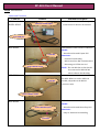
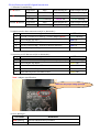
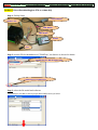
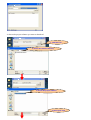
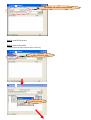
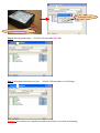
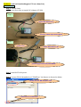
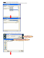
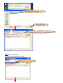
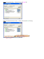
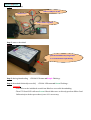
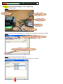
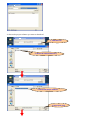
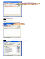
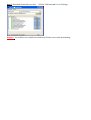
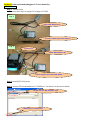
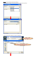
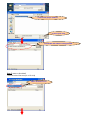
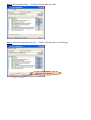
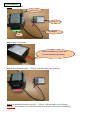
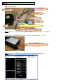
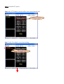
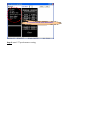
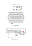
FP-004 User Manual
(Page05 ~ 14)Part
1. BA(Fujitsu CPU) Direct Downloading and
Indirect Downloading & White Card Calibration
(Page15 ~ 23)Part
2. BA(MicroChip CPU) Direct / Indirect Downloading
(Page24 ~ 25)Part
3. RS232 Interface Data Communication
(Page26 ~ 28)Part
4. BA testing on ICT BA test tool
Prepared by : H.L Tsai
2009/2/25
FP-004 User Manual
Step 0. Introductions
- Cables and Functions
Cable No.
Pictures
FP-004 main box
& WEL-RF303
Function Description
- WEL-RF303 cable should be always
external +12VDC input
connected to FP-004 for all activities.
to PC COM port
WEL-RF402
WEL-RF402 is used to below conditions :
Models :
BA and non-BA with Fujitsu CPU
to FP-004
Functions :
- Software Downloading
- RS232 interface data communication
- BA testing on ICT BA test tool
to kit’s RS232 socket
NOTE : The red dash line socket should
be connected to WEL-RF303
when software downloading.
WEL-RF401
ditto,
but WEL-RF401 is used to different
to FP-004
models, it depends on the RS323
connector style.
to kit’s RS232 socket
WEL-RF302
WEL-RF402 is used to below conditions :
Models :
to kit’s download port
BA and non-BA with MicroChip CPU
Functions :
Only for Software Downloading
to FP-004
- FP-004 Functions and LED Signals Introduction
1. Software Downloading :
PC Device
PC FP-004
Progresses
IDLE
DOWNLOADING
DOWNLOAD FINISH
LED color
Green Flashing
Purple ON
Green Flashing
Progresses
IDLE
DOWNLOADING
DOWNLOAD FINISH
LED color
Green Flashing
Purple ON
Green Flashing
IDLE
DOWNLOADING
DOWNLOAD FINISH
Green Flashing
Purple Flashing
Green Flashing
FP-004 Device Progresses
LED color
2. RS232 interface data communication(PC to BA Mode1) :
operations
Steps
LED color
1
Provide +12VDC to FP-004 by +12VDC adaptor(Note)
Green Flashing
2
Press RESET key once
Blue ON
3
Execute RS232 tool on PC
Blue ON
4.
Set DIP switch of BA / non-BA to RS232 interface
Blue ON
5
Turn ON BA / non-BA power and start to test
Blue ON
3. BA testing on ICT BA test tool(PC to BA Mode2) :
operations
Steps
LED color
1
Provide +12VDC to FP-004 by +12VDC adaptor(Note)
Green Flashing
2
Press RESET key twice
Yellow ON
3
Execute BA test tool on PC
Yellow ON
4.
Set DIP switch of BA / non-BA to RS232 interface
Yellow ON
5
Turn ON BA power and start to test
Yellow ON
Note : adaptor specification
make sure the proper voltage pole style
4. Error Messages :
LED Status
definitions
Red Flashing
Internal Flash Memory Problem
Red ON
Download Fail
- PC Tools Introduction
Functions
PC Tools
Software Downloading
FP4DT.exe(Ver. FP4DTS0004##########)
RS232 interface data communication(PC to BA Mode1)
ICT BA Test Tool PMGXXX0B.exe
BA testing on ICT BA test tool(PC to BA Mode2)
Fujitsu CPU ICT BA Test Tool PMGXXX0B.exe
MicroChip CPU ProductTestTool Version1.62
- PC COM Port Setting Introduction
PC Tools
COM Port Setting Methods(COM1 is recommended)
FP4DT.exe(Ver. FP4DTS0004##########)
by modifying “FP4DT.INI” file
ICT BA Test Tool PMGXXX0B.exe
can be set on executed program directly.
ProductTestTool Version1.62
can be set on executed program directly.
- FP-004 Software Version : FP004S0012##########(DD7D)
Part 1. BA(Fujitsu CPU) Direct Downloading and Indirect Downloading & White Card Calibration
Section 1. Direct Downloading(use P70 as a demo kit)
Step 1. Facility Setup
to PC COM port
+12VDC to P70
WEL-RF303
WEL-RF402
FP-004
P70
Step 2. execute FP-004 download tool “FP4DT.exe”, the feature is showed as below.
1. make sure it’s “Bill Acceptor” here
2. make sure it’s “COM1” here
Step 3. select the BA model and software
1. according to your BA to choose proper BA model(P Series) as below
2. choose the proper software you want to download
1. click this icon
2. choose the software directory
3. choose the proper software
4. click “Open” icon
5. BA model and software setting finished
Step 4. turn ON BA power
Step 5. start to download
1. select Direct Download function(PC to Device)
1. select “To Device” icon
2. click “Yes” icon
4. click “OK ” icon
3. push FP-004 RESET key
Step 6. during downloading <FP-004 LED status Purple ON>
Step 7. download finished(successful)
<FP-004 LED status Green Flashing >
Remark : You will hear the initialized sound from BA after successful downloading.
Section 2. Indirect Downloading(use P70 as a domo kit)
PC FP-004
Step 1. Facility Setup
- there are two ways to supply DC voltage to FP-004.
way 1
connet WEL-RF303 to PC
external +12VDC input from adaptor
way 2
+12VDC to P70
connet WEL-RF303 to PC
power supply from P70 by WEL-RF402
Step 2. turn ON FP-004 power
Step 3. execute FP-004 download tool “FP4DT.exe”, the feature is showed as below.
1. make sure it’s “Bill Acceptor” here
2. make sure it’s “COM1” here
Step 4. select the BA model and software
1. according to your BA to choose proper BA model(P Series) as below
2. choose the proper software you want to download
1. click this icon
2. choose the software directory
3. choose the proper software
4. click “Open” icon
5. BA model and software setting finished
Step 5. start to download
- select download function(PC to FP-004)
select “To FP-004” icon
Step 6. during downloading <FP-004 LED status Purple ON>
Step 7. download finished(successful)
<FP-004 LED status Green Flashing >
make sure message here
FP-004 Device
Step 1. Facility Setup
remove COM port socket
+12VDC to P70
must connect together
Step 2. start to download
push FP-004 RESET key longer than
3 seconds till LED Purple flashing
Step 3. during downloading <FP-004 LED status Purple Flashing>
Step 4. download finished(successful) <FP-004 LED status Green Flashing >
Remark :
- You will hear the initialized sound from BA after successful downloading.
- Then P70 Panel LED will turn Green ON and allow user to directly perform White Card
Calibration(see below procedures) once if it’s necessary.
White Card Calibration if it’s necessary
Step 1. P70 Panel LED shows Green ON and allow user to directly perform White Card Calibration.
Green ON
Step 2. slightly put White Card into P70 bill inserting mouth, then A7 will suck White Card a little
distance and then auto push White Card out after calibration finishing.
Step 3. P70 Panel LED becomes Dark(OFF) after calibration successful.
Dark
Part 2. BA(MicroChip CPU) Direct / Indirect Downloading
Section 1. Direct Downloading(use L70 as a demo kit)
Step 1. Facility Setup
+12VDC to L70
to PC COM port
WEL-RF303
FP-004
L70
WEL-RF302
Step 2. execute FP-004 download tool “FP4DT.exe”, the feature is showed as below.
1. make sure it’s “Bill Acceptor” here
2. make sure it’s “COM1” here
Step 3. select the BA model and software
1. according to your BA to choose proper BA model(L Series) as below
2. choose the proper software you want to download
1. click this icon
2. choose the software directory
3. choose the proper software
4. click “Open” icon
5. BA model and software setting finished
Step 4. turn ON BA power
Step 5. start to download
1. select Direct Download function(PC to Device)
select “To Device” icon
Step 6. during downloading <FP-004 LED status Purple ON>
Step 7. download finished(successful)
<FP-004 LED status Green Flashing >
Remark : You will hear the initialized sound from BA after successful downloading.
Section 2. Indirect Downloading(use L70 as a domo kit)
PC FP-004
Step 1. Facility Setup
- there are two ways to supply DC voltage to FP-004.
way 1
connet WEL-RF303 to PC
external +12VDC input from adaptor
way 2
+12VDC to L70
connet WEL-RF303 to PC
power supply from L70 by WEL-RF402
Step 2. turn ON FP-004 power
Step 3. execute FP-004 download tool “FP4DT.exe”, the feature is showed as below.
1. make sure it’s “Bill Acceptor” here
2. make sure it’s “COM1” here
Step 4. select the BA model and software
1. according to your BA to choose proper BA model(L Series) as below
2. choose the proper software you want to download
1. click this icon
2. choose the software directory
3. choose the proper software
4. click “Open” icon
5. BA model and software setting finished
Step 5. start to download
- select download function(PC to FP-004)
select “To Device” icon
Step 6. during downloading <FP-004 LED status Purple ON>
Step 7. download finished(successful)
<FP-004 LED status Green Flashing >
make sure message here
FP-004 Device
Step 1. Facility Setup
+12VDC to L70
FP-004
WEL-RF302
L70
Step 2. start to download
push FP-004 RESET key longer than
3 seconds till LED Purple flashing
Step 3. during downloading <FP-004 LED status Purple Flashing>
Step 4. download finished(successful) <FP-004 LED status Green Flashing >
Remark : You will hear the initialized sound from BA after successful downloading.
Part 3. RS232 Interface Data Communication(PC to Ba Mode1)
(use P77 as a demo kit)
Step 1. Facility Setup
to PC COM port
+12VDC to P77
WEL-RF303
WEL-RF402
FP-004
external +12VDC input from adaptor
P77
Step 2. Plug-in +12VDC adaptor to FP-004
Step 3. Press FP-004 RESET key once
<FP-004 LED status Green Flashing >
<FP-004 LED status Blue ON >
push FP-004 RESET key once
Step 4. execute “ICT BA Test Tool PMGXXX0B.exe” and follow below steps.
click “RS232” icon
Step 5. set P77 DIP switch to RS232 interface and turn ON P77 power
Step 6. P77 will auto send the 80h & 8Fh(power supply ON code) to PC(VMC) and PC(VMC) should
send 02h(ACK) to P77 within 2 seconds for active RS232 interface.
1. power supply ON code to VMC
2. VMC send ACK to P77 within 2 seconds
3. make sure P77 panel LED shows
multi-color and it means RS232 active
Step 7. start P77 RS232 bill accepting test
Part 4. BA testing on ICT BA test tool (PC to Ba Mode2)
(use P77 as a demo kit)
Step 1. Facility Setup
to PC COM port
+12VDC to P77
WEL-RF303
WEL-RF402
FP-004
P77
Must be connected together !!!
external +12VDC input from adaptor
Step 2. Plug-in +12VDC adaptor to FP-004
Step 3. Press FP-004 RESET key twice
<FP-004 LED status Green Flashing >
<FP-004 LED status Yellow ON >
push FP-004 RESET key once
Step 4. execute “ICT BA Test Tool PMGXXX0B.exe” and follow below steps.
Step 5. turn ON P77 power
Step 6. the P77 software version will be auto showed on the tool
software version
Step 7. click “Test Mode” icon to start testing
1. click “Test Mode” icon
2. test items will be auto showed here
Step 8. start P77 performance testing