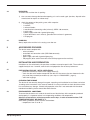
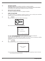
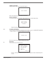
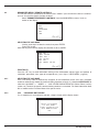
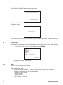
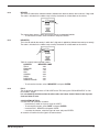
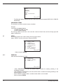
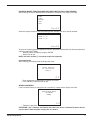
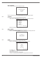
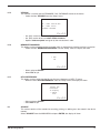
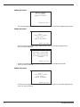
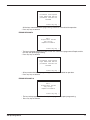
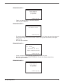
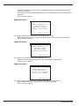
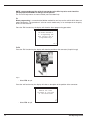
1
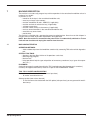
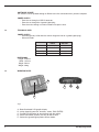
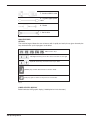
TKO
OPERATING MANUAL
™
A Member of the Kaba Group
ILCO TECHNICAL SUPPORT DEPT.
400 Jeffreys Rd., Rocky Mount, NC 27804
Tel: (800) 334-1381, Option 8
Fax: (800) 446-4702
™
(c) 2006 Kaba Ilco Corp. - Rocky Mount, NC
All Rights Reserved
2
TKO Operating Manual
INDEX
1
2
2.3
3
4
5
6
7
8
9
10
11
TKO Operating Manual
MACHINE DESCRIPTION ............................................................................................................... 5
1.1
MAIN CHARACTERISTICS .................................................................................................5
1.2
TECHNICAL DATA ...............................................................................................................6
1.3
WORKING PARTS ...............................................................................................................6
1.4
SYMBOLS ............................................................................................................................8
TRANSPORT
...............................................................................................................................8
2.1
PACKING..............................................................................................................................8
2.2
UNPACKING ........................................................................................................................9
HANDLING
...............................................................................................................................9
ACCESSORIES PROVIDED .............................................................................................................9
INSTALLATION AND PREPARATION..............................................................................................9
4.1
PREPARATION FOR USE - INITIAL OPERATIONS ...........................................................9
4.2
CHECKING FOR DAMAGE .................................................................................................9
4.3
ENVIRONMENTAL CONDITIONS .......................................................................................9
4.4
SOFTWARE UPDATING....................................................................................................10
REGULATION AND GAUGING .......................................................................................................10
USING THE MACHINE.................................................................................................................... 10
6.1
START-UP ......................................................................................................................... 10
6.2
PASSWORD.......................................................................................................................10
6.2.1
PASSWORD (MEMORIZED) ..............................................................................11
6.3
MAIN MENU .......................................................................................................................11
6.4
IMMOBILIZER MENU / REMOTE CONTROLS.................................................................12
6.4.1
SELECTING THE CAR MAKE ...........................................................................12
6.4.2
CAR MODEL NOT ENABLE...............................................................................12
6.4.3
CAR MODEL ENABLED.....................................................................................13
6.4.4
COMMUNICATION PROCEDURE WITH THE IMMOBILIZER ..........................13
6.5
PIN CODE READING ........................................................................................................13
6.5.1
DISABLED VEHICLE MODEL............................................................................13
6.5.2
ENABLED VEHICLE MODEL.............................................................................14
6.5.3
COMMUNICATION PROCEDURE FOR PIN CODE READING ........................14
6.6
7-4 PIN CONV. ...................................................................................................................14
6.6.1
PIN 7 ...................................................................................................................14
6.6.2
DEALER..............................................................................................................15
6.6.3
IMPORTER ........................................................................................................15
6.6.4
PIN 4 ...................................................................................................................15
6.7
SETUP .............................................................................................................................16
6.7.1
ENABLING .........................................................................................................16
6.7.2
LANGUAGE ........................................................................................................18
6.7.3
SERIAL NUMBER ..............................................................................................18
CLOCK.................................................................................................................18
6.7.4
6.7.5
VERSION ...........................................................................................................19
6.7.6
MEMORIZE PASSWORD...................................................................................19
6.7.7
KEYS REFERENCES ........................................................................................19
6.8
ARCHIVE ..........................................................................................................................19
SEARCH ............................................................................................................20
6.8.1
6.8.2
PRINTOUT .........................................................................................................21
6.8.3
ARCHIVE ERASE ...............................................................................................21
6.9
TEST
.............................................................................................................................21
KEYBOARD .......................................................................................................21
6.9.1
6.9.2
TEXT
.............................................................................................................................22
6.9.3
GRAPHICS ........................................................................................................................22
6.9.4
UPDATE SWITCH CAN .....................................................................................................22
WARNING/ERROR MESSAGES .....................................................................................................22
HELP MENU
.............................................................................................................................29
MAINTENANCE .............................................................................................................................31
9.1
CHECKING WIRING ..........................................................................................................31
WASTE DISPOSAL .........................................................................................................................31
ASSISTANCE ................................................................................................................32
11.1
HOW TO REQUEST SERVICE ...........................................................................32
3
GENERAL
The device is designed to the principles of European CE Directives. The materials used in its manufacture are not dangerous and their use complies with directives. Its design features make the machine and
all its components completely safe to use.
FURTHER RISKS
There are no further risks arising from the use of the machine.
PROTECTION AND SAFETY PRECAUTIONS FOR THE OPERATOR
The operations for which the machine has been designed are easily carried out at no risk to the operator.
SAFETY REGULATIONS
To operate under conditions of maximum safety do not use the device without reading and understanding
clearly the contents of this operating manual.
• Check the electrical wiring periodically; if the wires are worn they should be repaired or replaced.
• Never work with wet, greasy or oily hands.
• Disconnect the device from the mains when it is not in use or in order to carry out maintenance work.
• Never tug at the power supply wire; make sure it does not come into contact with oil, sharp edges
or heat.
• It is dangerous to use the device in areas at risk (damp or wet).
• Always work in a well lighted area.
• Keep the work area clean and remove all tools before turning on the machine.
• All visitors, children in particular, must keep at a safe distance and not touch the machine or
electrical wiring.
• Do not use the device for purposes different from those described in the Operating Manual.
POWER SUPPLY
The machine is supplied with electricity at 12 Vdc provided by the vehicle battery, or as an alternative
can be powered from a 15 Vdc universal feeder supplied with the machine.
TURNS ON
The machine turns on automatically when the connection (OBD II or Optional) is connected to the diagnostics socket or one of the feeder wires supplied with the machine is used.
IDENTIFICATION OF THE TKO DEVICE
The device has an identification plate showing its serial number ( fig. 1).
Fig. 1
(*) see chap. 10 “WASTE DISPOSAL“, page 32.
4
TKO Operating Manual
1
MACHINE DESCRIPTION
The machine is used to easily program keys with transponders in the centralized immobilizer units of a
number of car models.
In particular, it can:
- memorize all the keys in the centralized immobilizer unit;
- erase keys already in the memory;
- read the immobilizer ID code - IMMO ID (if applicable);
- read the mechanical code for the key (if applicable);
- add one or more keys;
- read the number of keys in the memory (if applicable);
- read any errors/anomalies in the centralized immobilizer unit;
- erase/zero any errors found;
- provide help.
The machine is provided with a password to prevent unauthorized use. Users have at their disposal a
functions menu to meet all possible requirements during operation.
NOTE: Once the machine is connected to the power mains it’s automatically switched on. To turn
it off exit from function and unplug the machine from the mains.
1.1
MAIN CHARACTERISTICS
OPERATING METHODS
- Adds or deletes keys from the immobilizer control unit by connecting TKO to the vehicle diagnostics
port.
SPECIAL FUNCTIONS
- Storage in the User Data Archive of all operations carried out;
- Multi-language program;
- Machine test;
- Help (operational help for: type and position of connectors, procedures, keys, types of transponders, etc...).
PASSWORD
A principle password is needed to enable the TKO (required every time the program is turned on),
issued by the supplier/distributor by means of a special “USE AGREEMENT FORM”.
TKO - FULL LOADED CONFIGURATION
Basic software (all makes included at the time of purchase)
- All makes are enabled for use.
Software update (new makes released)
- To use the new makes loaded with the SW update (after purchase) you may proceed in two different ways:
TKO Operating Manual
5
SOFTWARE UPDATE
The machine can be updated through an RS232 serial line connection with a personal computer.
POWER SUPPLY
- From the car through an OBD II connector;
- From the car through the cigarette lighter plug;
- From the mains through a universal feeder and special cable.
1.2
TECHNICAL DATA
POWER SUPPLY
- 8-45 Volt (typically 12Volt from the vehicle diagnostic inlet or cigarette lighter plug).
- Universal feeder:
Tension
Current
Frequency
Power
INPUT
OUTPUT
90-264 Vac
1.0Arms @ 90V
47-63 Hz
15 Vdc
1A
15 W
DIMENSIONS
Length: 220 mm
Width: 165 mm
Height: 50 mm
Weight: 300 g.
1.2
WORKING PARTS
B
C
D
E
A
Fig. 2
A - Retro illuminated LCD graphic display
B - 23-key keypad (numerical, functions, arrows, ESC, ENTER)
C - Parallel Port (25 Poles) to communicate with the vehicle
D - Serial Port RS232 (9 Poles) use only for Serial cable
E - Socket for cigarette lighter power cable or feeder
6
TKO Operating Manual
F - Standard OBD II cable
G - Cigarette lighter power
cable
H - Feeder
J - Serial cable
MAIN FEATURES
KEYPAD
The machine keypad allows the user to interact with it rapidly and easily. At any given time only the
keys involved in the cycle in progress are enabled.
HELP function keys
Left-Right arrow keys, move the cursor to the left or to the right
Up-Down arrow keys, move the cursor up or down
(ENTER) key confirms data entered or selection made
(ESC) key quits or returns to the previous screen/status
Fig. 3
LIQUID CRYSTAL DISPLAY
Retro illuminated LCD graphic display (128x64 pixel or 21x8 characters).
TKO Operating Manual
7
1.4
SYMBOLS
The box shows the machine screen and relative displays, as shown below:
1
2
3
>4
5
6
7
-
- MAIN MENU IMMOBILIZER
REMOTE CONTROLS
PIN CODE READING
7-4 PIN CONV.
SET UP
DATA BASE
TEST
EfgL N
Methods for selecting a specific function:
- Use the arrow Left/Right keys, the point where the cursor “>”shows the item required, then press
ENTER;
- Digit a number (xx) from the keypad to access the item required directly from the menu.
1
2
>3
4
-
- MAIN MENU -
KEYBOARD
TEXT
GRAPHICAL
UPDATE SWITCH CAN
EfgL N
Example:
to access the GRAPHICS TEST menu (73) either use the arrows to select first the TEST menu (7), press
ENTER, then the GRAPHICS menu (3) and press ENTER, or digit (73) which corresponds to the
GRAPHICS TEST (73).
2
TRANSPORT
The machine and its components are easily transported by one person and its handling does not incur
any hazards.
2.1
PACKING
The packing ensures safe transport for the machine and protects all its parts. To avoid knocks damaging
the machine, we recommend using the original carrying case and packing every time it is transported.
Fig. 4
8
TKO Operating Manual
2.2
UNPACKING
To remove the machine from its packing:
1) take care not to damage the box when opening as it can be used again (transfers, dispatch to the
manufacturer for repairs or maintenance).
2) check the contents of the packing case, which comprise:
- 1 carrying case;
- 1 machine;
- 1 universal feeder;
- 1 centralized unit connecting cable (universal), OBDII - 00 connector;
- 1 serial cable;
- 1 power supply cable with cigarette lighter plug;
- 1 set of documents: user’s manual, guarantee form and user’s agreement;
- 1 CD program
2.3
HANDLING
Always replace the machine in its carrying case after use.
3
ACCESSORIES PROVIDED
The device comes complete with:
- universal feeder;
- centralized unit connection cable (OBD II-00 connector);
- serial cable;
- power supply cable with cigarette lighter plug;
- CD program (to be used in the event of loss of the program on the machine).
4
INSTALLATION AND PREPARATION
Installation can be carried out by the purchaser and does not require special skills. The machine is
supplied ready for use - however, some checks and preparation are necessary before use.
4.1
PREPARATION FOR USE - INITIAL OPERATIONS
- power the machine by means of the supply socket (E);
- check that the serial number stamped on the device is the same as the one shown on the display; enter the password (to enable use) (see chap. 6.2 “PASSWORD“, page 8);
- select the language;
4.2
CHECKING FOR DAMAGE
The device will not normally damage if transport, unpacking and installation have all been carried out
according to the instructions in this manual; however it is always advisable to check that the machine
has not suffered any damage. Should faulty operation arise that is not connected with the abovementioned conditions, please contact After-Sales Service.
4.3
ENVIRONMENTAL CONDITIONS
To ensure that the best use is made of the machine and that the keys with transponders produced
work properly, it is important to bear in mind operating conditions and temperature.
Given the characteristics of the transponders on the keys, in order to memorize them, THE
TEMPERATURE MUST BE ABOVE 5° C.
Ideal working conditions for the machine are therefore:
- temperature: from 5° to 40° C.
TKO Operating Manual
9
4.4
SOFTWARE UPDATING
The machine software can be updated by connection to a personal computer.
ATTENTION: the RS232 socket for connection to the PC is located on the front, near the display.
Use the RS232 serial cable provided and follow the instructions for updating.
5
REGULATION AND GAUGING
The machine is designed not to require any gauging or regulation.
6
USING THE MACHINE
This chapter describes all the operations required to memorize, erase, or add keys to the centralized
immobilizer unit by connecting TKO to the vehicle diagnostics input.
6.1
6.1
START-UP
When the machine is turned on the display shows the logo:
After a few seconds the following message appears:
- TKO Update: XXXXXXX
S.N.: XXXXXXXXXXXXX
(F1) to continue
The words “Update: XXXXXXX” give the level of updating for the program and database.
The words “S.N.: XXXXXXXXXXXXX” give the machine serial number.
Check that the serial number shown on the display is the same as that on the document “USER’S
AGREEMENT” and on the label attached to the back of the machine.
Press F1 to continue.
6.2
6.2
PASSWORD
When selection has been made, the following message appears:
INSERT PASSWORD
XXXXXXXX
To use the machine enter the password issued by the supplier/dealer, comprising 8 numerical characters.
- enter the password and press ENTER.
10
TKO Operating Manual
CORRECT PASSWORD
If the password is correct, the message below appears:
RIGHT PASSWORD
After a few seconds the program enters the main menu.
WRONG PASSWORD
If a wrong password has been entered, a beep advises the user and the display shows:
WRONG PASSWORD
INSERT PASSWORD
XXXXXXXX
- Repeat the operation and press ENTER.
6.2.1
PASSWORD (MEMORIZED)
If the password has already been memorized on the machine ( chap. 6.7.6 “MEMORIZE PASSWORD
“, page 18), when F1 is selected the following message appears:
PASSWORD SAVED
Wait a few seconds for the display to show the main menu.
6.3
MAIN MENU
There are two ways to choose the menu:
1
2
3
>4
5
6
7
-
- MAIN MENU IMMOBILIZER
REMOTE CONTROLS
PIN CODE READING
7-4 PIN CONV.
SET UP
DATA BASE
TEST
EfgL N
- Use the , arrow keys for selection then press ENTER, or digit the number corresponding to the
function.
TKO Operating Manual
11
6.4
IMMOBILIZER MENU / REMOTE CONTROLS
This function contains the database of vehicle makes / models / years for which the device is enabled
and can carry out the specific functions involved.
- Select “IMMOBILIZER/REMOTE CONTROLS”; from the MAIN MENU to view a list of car
makes on the display.
- MENU IMMOBILIZER AUDI
SEAT
SKODA
> VOLKSWAGEN
OPEL
FORD
EfgL N
SELECTING THE CAR MAKE
- Use the arrow keys to select the make, then press ENTER.
- Press ESC to quit.
After selecting the make the display will show the list of car models.
- VOLKSWAGEN BORA (98- )
CADDY (95-99)
CADDY (00- )
> GOLF (95-99)
GOLF (00- )
GOLF CABRIO (95-99)
EfgL N
FUNCTION F1
Press the “F1” key to show information relating to the make/model selected (type and position of
connectors, procedures, keys, types of transponder, etc.) (see chap. 8 “HELP MENU“, page 29).
6.4.1
SELECTING THE CAR MAKE
TKO is not always able to automatically recognize all the immobilizer central units and is therefore
unable to automatically choose the communication procedure to launch. It is therefore NECESSARY to
select the right MAKE g
MODEL g
ANY OTHER CHARACTERISTICS (Petrol, Diesel, red key
system, etc.) to which the specific communication procedure is associated. For more information about
the car model see the Functions Menu of the specific make.
6.4.2
6.4.2
CAR MODEL NOT ENABLE
If a car model that is not enabled is selected, a beep is heard and the display shows:
- VOLKSWAGEN Device not enabled
for this model.
Insert password from
menu ENABLE FLAGS
(51)
12
L
TKO Operating Manual
6.4.3
CAR MODEL ENABLED
If a car model that is enabled has been selected, the display shows:
Insert the key
and turn on
the console
LN
- Press ESC to quit.
- Press ENTER to continue.
6.4.4
COMMUNICATION PROCEDURE WITH THE IMMOBILIZER
The following message appears:
Please wait
connecting …
The communication procedure with the immobilizer starts; if the car model selected is correct and the
immobilizer is detected, the Functions menu by make appears, otherwise an error message is shown
(see chap. 7 “WARNING/ERROR MESSAGES“, page 22).
6.5
PIN CODE READING
This function can read (only for certain VAG models) the vehicle PIN CODE directly from the OBD-II socket.
Select “PIN CODE READING” from the MAIN MENU and press ENTER.
6.5.1
DISABLED VEHICLE MODEL
If the function is not enabled a beep is heard and a message appears:
- PIN CODE READING Device not enabled
for this model.
Insert password from
menu ENABLE FLAGS
(51)
TKO Operating Manual
L
13
6.5.2
ENABLED VEHICLE MODEL
If the function is enabled the following message appears:
Turn the ignition on!
Press any key …
6.5.3
COMMUNICATION PROCEDURE FOR PIN CODE READING
The display shows:
Please wait
connecting …
The communication procedure starts with the vehicle control panel memory. Different screens may
appear, according to the type of control panel on the vehicle.
6.6
7-4 PIN CONV.
This function is used to convert a 7-digit pin code (issued by the dealer) to a 4-digit pin code for use on
VOLKSWAGEN(r), AUDI(r), SEAT(r) and SKODA(r) vehicles.
- To activate the function, select “7-4 PIN CONV.” and press ENTER.
- VAG CONVERTER PIN 7
DEALER
IMPORTER
> PIN 4
DATE (XX/XX/XXXX)
EfgL N
- To activate the function, select ENTER.
- Press ESC to exit.
6.6.1
PIN 7
This is a 7-digit code issued by the dealer.
How to apply for the code:
- Use the function “READ IMMO ID” in TKO to read the series number of the central unit.
- Provide the authorized dealer with the following data:
• Central unit series number
• Chassis number
• Copy of log book
• ID document for applicant
14
TKO Operating Manual
6.6.2
DEALER
This is the ID code for the authorized dealer (different from dealer to dealer) who issues the 7-digit code.
The code is included in the rubber stamp used by the dealer to validate work on the vehicle.
The stamp shown above is often found in the vehicle maintenance booklet.
- To activate the function, select “DEALER” and press ENTER.
6.6.3
IMPORTER
This is the ID code for the country in which the 7-digit code is applied for (different from country to country).
The code is included in the rubber stamp used by the dealer to validate work on the vehicle.
Table of currently known Importer Codes.
COUNTRY
IMPORTER CODE
ITALIA
- 264
ENGLAND
- 210
ISRAEL
- 730
USA
- 444
CANADA
- 999
SPAIN
- 572
PORTUGAL
- 261
RIUNION ISLAND
- 387
- To activate the function, select “IMPORTER” and press ENTER.
6.6.4
PIN 4
This is the 4-digit code to enter as PIN CODE on the TKO during the “PROG.NEW KEYS” or “No.
KEYS MEM.” stages.
It is calculated by the device when the other codes are known: Code7, Dealer Code, Importer
Code and date of issue.
CALCULATION OF PIN 4
calculate the PIN 4 proceed as follows:
- Insert the day, month and year of issue of CODE 7
- To activate the function, select “DATE” and press ENTER.
- Insert the PIN 7, DEALER and importer CODE.
- o activate the function, select the figure to insert and press ENTER.
An asterisk will confirm that the figure has been entered.
TKO Operating Manual
15
- VAG CONVERTER PIN 7
DEALER
IMPORTER
> PIN 4
DATE (XX/XX/XXXX)
EXIT
EfgL N
- The PIN 4 will appear automatically once all the data have been entered (DATA, PIN 7, DEALER,
IMPORTER).
ADVANCED OPTIONS
The function can also be used for inverse calculation.
Example:
If you have the correct data for:
- The date of issued of CODE;
- 3 of the 4 codes required;
The missing CODE can be found. Just insert the 3 items of known data and the missing figure will
appear automatically.
6.7
SETUP
This section contains the various setting menus for the machine.
Select “SETUP” from the main menu and press ENTER.
>1
2
3
4
5
6
7
-
- SETUP ENABLE FLAGS
LANGUAGE
SERIAL NUMBER
CALENDAR/CLOCK
RELEASE
STORE PASSWORD
KEYS REFERENCE
EfgL N
- Select and press ENTER.
6.7.1
ENABLING
After selection the display will show:
- ENABLING > 1 - IMMOBILZER
2 - REMOTE CONTROLS
3 - TOKEN (X)
EfgL N
-
Select IMMOBILIZER to view the vehicle makes available for entering enabling in the
“Immobilizer” function;
- Select REMOTE CONTROLS to view the vehicle makes available for entering enabling in the
“Remote Controls” function;
- Select TOKEN to view the tokens available; further tokens can be loaded.
- Select and press ENTER.
16
TKO Operating Manual
ENABLING MAKES (FUNCTION AVAILABLE ONLY FOR TKO FULL LOAD DEVICES)
After selecting the menu “IMMOBILIZER or REMOTE CONTROLS” the display will show:
> AUDI
FORD
NISSAN
OPEL
SEAT
- ENABLING -
EfgL N
Select the required make to view the enabling levels available and those already enabled.
LEVEL
LEVEL
> LEVEL
ENABLING MAKE 1 (*)
2 (*)
3 (*)
EfgL N
To enter the enabling password applied for with the document provided with the software update disk
(software application FORM).
- Select the level of enabling and press ENTER.
- Select ESC to quit.
NOTE: the levels marked (*) are already enabled for operation
PASSWORD ENTRY
After selecting the enabling level the display will show:
- ENABLING MAKES Insert Password
for abilitation
LEVEL X
LN
- Enter the password comprising 6 numerical characters.
- Press ENTER to continue, ESC to quit.
WRONG PASSWORD
If the Password entered is wrong the user is warned by a beep and the display will show:
PASSWORD
ABILITATION GROUP
CAR BRAND
WRONG
LN
- Repeat the operation.
ATTENTION: only 3 attempts are allowed, after which the device is blocked. To release disconnect the device from the power supply, then re-connect.
TKO Operating Manual
17
RIGHT PASSWORD
If the Password entered is right, the display will show:
ABILITATION GROUP
CAR BRAND
ENABLED
From this moment the device is enabled to operate at the enabling level selected.
6.7.2
LANGUAGE
This function is used to select the language for the device.
- Select the item “LANGUAGE” from the “Setup” menu, the display will show:
>1
2
3
4
5
6
7
-
- LANGUAGE ITALIANO
DEUTSCH
FRANCAIS
ENGLISH
ESPANOL
GREEK
PORTUGUES
EfgL N
- Select the language and press ENTER
6.7.3
SERIAL NUMBER
This function is used to view the serial number of the machine.
- Select the item “SERIAL NUMBER” from the “Setup” menu; the display will show:
TKO
SERIAL NUMBER
XXXXXXXXXXXXX
6.7.4
CLOCK
This function is used to read the machine’s internal clock.
- Select the item “CLOCK” the “Setup” menu; the display will show:
- CALENDAR/CLOCK TIME:
XX:XX:XX
DATE:
XX/XX/XXXX
EfgL N
-
18
Press ESC to quit.
Select ENTER to continue.
Follow the instructions given by the device.
The user is not enabled to the TIME/DATE changing functions of the clock.
TKO Operating Manual
6.7.5
VERSION
This function is used to view the FIRMWARE / SW / DATABASE version on the device.
- Select the item “VERSION” from the “Setup” menu:
- TKO -
Ver. (SW): XXX.XX.XXX
Ver. (DB): XX.XX
Release: XXXXXXX
EfgL N
- Ver. (SW): version of the internal program
- Ver. (DB): version of the car makes-models database
- Update: database update level given by the manufacturer’s code.
6.7.6
MEMORIZE PASSWORD
This option can be used to bypass the password, which is required every time the machine is turned on.
- Select the item “MEMORIZE PASSWORD” from the “Setup” menu, the display will show:
- MEMORIZE PASSWORD > YES
NO
EfgL N
- Select and press ENTER
- Select ESC to quit.
6.7.7
KEYS REFERENCES
This option can be used to view the Silca or Ilco keys references on HELP F1 menu.
- Select the item “KEYS REFERENCES” from the “Setup” menu; the display will show:
- KEYS REFERENCES Select the
reference
to display
> SILCA
ILCO
EfgL N
- Select and press ENTER.
- Select ESC to quit.
6.8
ARCHIVE
This section contains all the controls for searching, printing, or deleting user data stored in the device
memory.
Select “ARCHIVE” from the MAIN MENU and press ENTER; the display will show:
TKO Operating Manual
19
- DATA BASE 1 - SEARCH
2 - PRINT DATA
3 - ARCHIVE RESET
EfgL N
6.8.1
SEARCH
This control is used to make a search for:
- POS.: Position in which the operation carried out was saved
- DATE: date on which the operation was memorized
- MAKE: car make
- MODEL: car model
- SURNAME: customer’s surname
- NUMBER PLATE: car number plate
Select “SEARCH” from the “ARCHIVE”; menu; the display will show:
- SEARCH POS.:
XX
DATE:
XXXXXXXX
> BRAND:
XXXXXXXXXX
MODEL:
XXXXXXXXXX
SURNAME:
XXXXXXXXXX
REG. NO.:
XXXXXXXXXX
EfgL N
- Use the , , arrow keys to place the cursor in the required field and press .
- Enter the characters to be searched for.
- Press ENTER to proceed the search.
SEARCH METHOD
(POS.) (DATE)
- Digit a number or the date and press ENTER: the display will show the corresponding record.
- Use the key to view the previous record, the key to view the next record.
(MAKE) (MODEL) (SURNAME) (NUMBER PLATE)
- Digit the initial or part of the text to be searched for and press ENTER: the display will show the
first record available in order of position (POS.)
- Use the key to view the previous record, the key to view the next record.
If none of the search criteria are met or there are no data in the archive, the display will show:
NO INFORMATION
RECOVERED
- Press any key and repeat the search.
20
TKO Operating Manual
USER DATA
User data that meet the criteria are shown as follows:
- USER DATA (0) DATE:
20/03/2001
BRAND:
AUDI
MODEL:
A4
YEAR:
(95-98)
ROSSI
SURNAME:
NAME:
MARIO
REG NO.:
KEYS:
PIN:
IMMO ID:
EfgL N
TV9988773
3
4567
(F1)
Use the fg keys to view the user data in sequence (depending on the search selected).
- Press key F1 to view the IMMO ID.
6.8.2
PRINTOUT
At present this function is not active.
6.8.3
ARCHIVE ERASE
This function is used to erase all user data in the archive.
- Select “ERASE ARCHIVE” from the “ARCHIVE” menu; the display will show:
- ARCHIVE ERASE > NO
YES
EL N
- Select and press ENTER.
- Select ESC to quit.
6.9
TEST
This section contains all the controls with which to carry out a rapid operational test on the machine.
Select “TEST” from the main menu.The display will show:
1
>2
3
4
-
- TEST KEYBOARD
TEXT
GRAPHICAL
UPDATE SWITCH CAN
EfgL N
6.9.1
KEYBOARD
This function is used to test the operation of all the keys on the device keypad.
- Select “KEYPAD” from the “TEST” menu.
- To carry out the test press all the keys on the device, one after the other; to quit press any key
three times.
TKO Operating Manual
21
TEST RESULT:
- TEST PASSED (all the keys are working properly)
- TEST FAILED (not all the keys has been pressed) possible causes:
- One or more keys not working properly
- The same key has been pressed for three times in a row.
6.9.2
TEXT
This function is used to test the operation of the display in the Text mode.
- Select “TEXT” from the “TEST” menu.
0123456789abcdefghijk
0123456789abcdefghijk
0123456789abcdefghijk
0123456789abcdefghijk
0123456789abcdefghijk
0123456789abcdefghijk
0123456789abcdefghijk
0123456789abcdefghijk
- Check that the characters on the display correspond.
- Press a key to quit.
6.9.3
GRAPHICS
This function is used to test operation of the display in the GRAPHICS mode.
- Select “GRAPHICS” from the “TEST” menu and check that all the pixel on the display are illuminated.
- Press a key to quit.
6.9.4
UPDATE SWITCH CAN
This function is used for manual updating of the internal software for the CAN BUS SWITCH.
- Select “UPDATE CAN BUS SWITCH” from the “TEST” menu.
- The display will show:
OPTIMIZATION IN
PROGRESS
Updating of the SWITCH CAN BUS start now.
When updating is complete the TKO re-starts automatically.
7
WARNING/ERROR MESSAGES
ERROR MESSAGE 1
- COMMUNICATION ERROR ECU
disconnected
Press ESC to quit
22
TKO Operating Manual
ERROR MESSAGE No. 2
Communication error
Press any key …
- These error messages may appear during communication with the immobilizer if the connection
is cut off, or in the case of physical disconnection between the device and immobilizer: disconnect the device from the socket and repeat the operation.
ERROR MESSAGE 3
Not recognized
protocol
Press any key …
- This message appears when a car model is selected but none of the queries from the different
protocols used receive a coherent reply from the immobilizer. Check that you have selected the
right make model.
ERROR MESSAGE 4
Not valid
pin
Press any key …
- This message appears when the PIN CODE entered is not properly composed or is not recognized by the immobilizer.
ERROR MESSAGE 5
Key not programmed
Repeat procedure
Press any key …
- This message appears when key programming is not successful. Repeat the procedure.
TKO Operating Manual
23
ERROR MESSAGE 6
REMOTE CONTROL
not programmed
Repeat procedure
Press any key …
- This message appears when remote control programming is not successful. Repeat the procedure.
ERROR MESSAGE 7
- PROG. NEW KEYS KEY i
Acquisition failed
Key faulty
Repeat Procedure
Press any key …
- The key to be programmed is faulty, replace with a new key and repeat programming.
- Press any key to continue
- PROG. NEW KEYS -
Procedure interrupted
Keys memorized before
procedure started are
enabled
Press any key …
- All the keys memorized before programming started are still enabled for operation.
- Press any key to continue.
ERROR MESSAGE 8
- PROG. NEW KEYS KEY i
Acquisition failed
Key faulty
Repeat Procedure
Press any key …
- The key to be programmed is a wrong key, replace with the right key and repeat programming.
- Press any key to continue
24
TKO Operating Manual
- PROG. NEW KEYS Procedure interrupted
Keys memorized before
procedure started are
enabled
Press any key …
All the keys memorized before programming started are still enabled for operation.
- Press any key to continue.
ERROR MESSAGE 9
- PROG. NEW KEYS KEY i
Acquisition failed
Key faulty
Repeat Procedure
Press any key …
- The key to be programmed has been erased and cannot be re-programmed. Replace with a
new key and repeat programming.
- Press any key to continue
- PROG. NEW KEYS -
Procedure interrupted
Keys memorized before
procedure started are
enabled
Press any key …
- All keys memorized before programming started are still enabled for operation.
- Press any key to continue
ERROR MESSAGE 10
- PROG. NEW KEYS KEY i
Acquisition failed
Key faulty
Repeat Procedure
Press any key …
- The key to be programmed has already been programmed; repeat programming.
- Press any key to continue.
TKO Operating Manual
25
- PROG. NEW KEYS Procedure interrupted
Keys memorized before
procedure started are
enabled
Press any key …
- All keys memorized before programming started are still enabled for operation.
- Press any key to continue
ERROR MESSAGE 11
- PROG. NEW KEYS KEY i
Acquisition failed
Key faulty
Repeat Procedure
Press any key …
- The key to be programmed is without a transponder. Replace with a new key with transponder
and repeat programming.
- Press any key to continue.
- PROG. NEW KEYS -
Procedure interrupted
Keys memorized before
procedure started are
enabled
Press any key …
- All keys memorized before programming started are still enabled for operation.
- Press any key to continue
ERROR MESSAGE 12
- PROG. NEW KEYS Key memorization failed
EEPROM memory error
Press any key …
- There is an internal anomaly in the immobilizer.
- Press any key to continue.
26
TKO Operating Manual
ERROR MESSAGE 13
- PROG. NEW KEYS Body Computer
not properly
programmed
Press any key …
- There is an internal anomaly in the body computer.
- Press any key to continue
ERROR MESSAGE 14
- RKE PROGRAM Procedure failed
Press any key …
- The remote control to be programmed is not the right one, or is broken, or errors have occurred
during programming. Make sure the remote control is the right one and efficient, then repeat
programming.
- Press any key to continue
ERROR MESSAGE 15
- PROG. NEW KEYS Error Found:
XXXX
Eliminate the error
before programming keys
and/or remote controls
Press any key …
- If errors are found in the immobilizer, programming cannot take place.
- Delete the errors using the “DELETE ERRORS” function, then repeat programming.
- Press any key to continue
ERROR MESSAGE 16
- PROG. NEW KEYS Body Computer
not properly
programmed
Press any key …
TKO Operating Manual
27
- The Body computer (main control unit) is not properly programmed; programming operations
cannot be carried out.
- Have the body computer properly programmed by an authorized dealer, then proceed with programming.
- Press any key to continue.
ERROR MESSAGE 17
- RKE PROGRAM REMOTE CONTROL NO. XX
Learning failed
Detective rem.control
Repeat the procedure
Press any key …
The remote control to be programmed is not the right one or is faulty.
- Repeat programming, making sure that the remote control is the right one and operational.
- Press any key to continue.
ERROR MESSAGE 18
- RKE PROGRAM REMOTE CONTROL NO. XX
Learning failed
Run-down battery
Repeat the procedure
Press any key …
The battery in the remote control to be programmed is flat.
- Replace the remote control battery with a new one and repeat programming.
- Press any key to continue.
ERROR MESSAGE 19
- RKE PROGRAM REMOTE CONTROL NO. XX
Learning failed
Rem. ctrl alr. acquired
Repeat the procedure
Press any key …
The remote control to be programmed is already in the memory and operational.
- Use a remote control not yet programmed and repeat programming.
- Press any key to continue.
28
TKO Operating Manual
ERROR MESSAGE 20
- RKE PROGRAM REMOTE CONTROL NO. XX
Learning failed
Press any key …
Some errors have occurred during programming. Repeat programming, making sure that the remote
control to be programmed is the right one and operational, and that the immobilizer system has no operational anomalies (use the reading errors function).
Press any key to continue.
8
HELP MENU
This function is enabled after the selection of car make and model.
The following help functions are available:
F1
Press the function key “F1” to read information relating to the MAKE/MODEL selected:
- MAKE
- MODEL
- YEAR
- REFERENCE (SILCA)
- ORIGINAL TRANSPONDER
- MEMORIZATION PROCEDURE
- MAX. NUMBER OF KEYS THAT CAN BE MEMORIZED
- CONNECTOR TO USE
- ADAPTER TO USE
- CONNECTOR POSITION
Example:
- CAR MAKE A2: (95-96)
CONNECT:
00
Pos.Con.:
(F3-F4)
KEY REF:
HU66AT6
Orig.Tr.:
MEG/CR
RW2/RW3 ID: 48
F2-F3-F4
EfgL N
N.KEY:
8
Self P.:
(F2)
- Connect: type of cable to use to connect with the immobilizer (see ID label on the cable);
- Pos.Con: position on the vehicle of the diagnostics socket to which the device can be connected;
press F3 - F4 to access the information.
- Key Ref.: Silca key to use for the car model selected
- Orig.Tr.: type of transponder used on the original key
- RW2/RW3 ID: ID code for transponder used by RW2/RW3.
- No. Key: max. number of keys that can be memorized on the vehicle (when the maximum number
of keys is reached, a key must be erased from the memory in order to memorize a new one).
- Self P.: description of the direct programming procedure.
TKO Operating Manual
29
NOTE: correspondence of the original transponder to the Silca key to be used should be
checked with the RW2/RW3 for the type of transponder.
The F2-F3-F4 help menus are now available (see last bottom line).
F2
Direct programming is a memorization/deletion method for new keys on the vehicle which does not
require diagnostics. The procedure is active on certain models only, as its use depends on the policy
of the car manufacturer.
Press the “F2” function key; the display will show the direct programming procedure:
- CAR MAKE -
ON BOARD PROGRAM A
1 - Programming new
keys without use of
programmed keys
Efg
F3-F4
Press the “F3” function key, the display will show the position of the connector (Graphic Image)
Fig. 6
- Select ESC to quit.
Press the “F4” function key, the display will show a description of the position of the connector:
- POSITION -
Remove the cover
situated at the side
of the hand brake
L
- Select ESC to quit.
30
TKO Operating Manual
9
MAINTENANCE
ATTENTION: for repairs or replacement of parts for maintenance, the ‘CE’ mark is guaranteed
only if original spare parts provided by the manufacturer are used.
The machine does not require special maintenance.
ATTENTION: do not open the machine for any reason whatsoever)
Before starting any type of maintenance (checks or replacement of parts) read the following instructions:
- Do not carry out any maintenance operations with the machine turned on;
- Always disconnect from the mains;
- Follow the instructions in the manual;
- Use original spare parts.
FAULT
PROBABLE CAUSE
DISPLAY:
- DISPLAY IS BLANK WITH MACHINE ON
A) CHECK POWER SUPPLY CONFIGURATION
KEYPAD:
-NOT RESPONDING TO CONTROLS
NO COMMUNICATION WITH THE
CENTRALIZED UNIT
B) CHECK CONNECTION WIRING
- REPLACE DISPLAY (AFTER-SALES SERVICE)
- REPLACE ELECTRONIC CONTROL BOARD
(AFTER-SALES SERVICE)
A) CHECK CONNECTION WIRING
- REPLACE KEYPAD (AFTER-SALES SERVICE)
A) CHECK THAT THE RIGHT CAR MODEL HAS BEEN
SELECTED
B) CHECK THE WIRING
The instructions above relating to the probable causes of the faults described should be considered
indicative and not a complete list of the possible causes of malfunctions.
Contact the After-Sales Service in the event of any other problems arising.
9.1
CHECKING WIRING
If it is necessary to check the machine’s internal wiring, proceed as follows:
- Disconnect the supply wire;
- Detach any other wires connected to the machine;
- Remove the 4 screws located on the back of the machine;
- Remove the cover carefully, paying attention to the wiring;
- Check that all the connectors are properly in place.
10
WASTE DISPOSAL
EU regulations establish special arrangements for the disposal of waste (*).
WASTE DERIVING FROM THE MACHINE
The machine produces no waste during its use.
MACHINE
The machine is made of re-usable materials. Re-cycling is recommended ecological practice.
PACKING
The machine is consigned in a cardboard packing box which can be re-used if undamaged. When it is to be
thrown away it is classified as solid urban waste and it should be placed in the special paper collecting bins.
(*) Waste is any substance or object deriving from human activity or natural cycles, thrown away or to be thrown away.
TKO Operating Manual
31
DISPOSING OF THE BATTERY
The battery (fig. 7 must be disposed of according to current regulations.
Fig. 7
INFORMATION FOR USERS
as per art. 10 of Directive 2002/96/CE of 27/01/2003
regarding waste from electric and electronic appliances (RAEE),
• The symbol illustrated above, also found on the machine, indicates that it has been placed on the
market and must be included in separate rubbish collection when the user wishes to dispose of it
(including all components, sub-assemblies and consumables that are integrated in the product).
• For information about the collection system for such appliances please contact SILCA S.p.A. or
another subject registered in the various National Rolls for other countries in the European Union.
Household waste (or of similar origin) can be included in the separate collection system for urban
waste.
• On purchasing a new appliance of equivalent type, the old one can be consigned to the dealer.
The dealer will then contact whoever is responsible for collecting the appliance.
• Suitable separate collection of the unused appliance and its dispatch for treatment, recovery and
environmentally compatible disposal, makes it possible to avoid potential negative effects on the
environment and human health, and aids recycling and the recovery of the materials used.
• Unauthorized disposal of the product by users involves the application of the sanctions provided
for in received Directives 91/156/CE and 91/689/CE.
11
ASSISTANCE
Silca provides full assistance to purchasers of the machine. To ensure complete safety for the operator,
any job not specified in this manual should be carried out by the manufacturer or in the special Service
Centers recommended by Silca. On the back cover of this manual there is a list of the Service Centers
and relative addresses.
11.1
32
HOW TO REQUEST SERVICE
The guarantee attached to the machine ensures free repairs or replacements of faulty parts within 12 months
of purchase. All other service calls must be arranged by the customer with Ilco or with a Ilco service center.
(See inside front cover of this manual for contact information.)
TKO Operating Manual