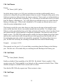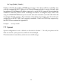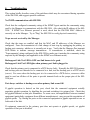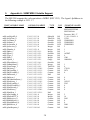
1
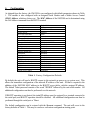
SM-2508 Gigabit Ethernet Link Protector Shore Microsystems, Inc. Table of Contents 1.1................... Copyright Information 1.2........................ Limited Warranty 1.3................................ Products 1.4.................... Revision Information 1.5..................... Contact Information 2.................................. Features 3................................. Equipment 3.1.............................. Interfaces 3.1.1......................... Managed Ports 3.1.2.................. Front Panel Controls 1.1.3............. RS-232 Terminal Interface 1.1.4.... Ethernet Management Port Interface 1.1.5............... Power Input Connections 1.2.............................. Indicators 1.2.1.............. Device Status Indicators 1.1.2................ Port Status Indicators 1.3............................ Applications 1.3.1......................... Server Backup 1.3.2....................... Firewall Backup 4............................... Terminology 5............................. Configuration 5.1...................... Port Configuration 5.2...................... SNMP Configuration 5.2.1......................... Agent Address 5.2.2........... Manager Addresses And Traps 5.2.3.................... System Information 5.2.4..................... Community Strings 5.3............................ SNMP Control 5.4................................ Password 5.5........................ Network Password 5.6............................... Baud Rate 5.7............................. Port Groups 5.8............. Saving System Configuration 5.9......... Restoring Default Configuration 6.......................... System Operation 6.1............................. Port States 6.1.1...................... Normal Operation 6.1.2.............................. Disabled 6.1.3......................... Forced Backup 6.2................... Front Panel Operation 6.3....................... Console Operation 6.4.......................... SNMP Operation 7......................... Command Reference 1.1............................. Acknowledge 1.2..................................... ARP 2 4 4 4 4 4 6 7 7 7 7 8 8 8 9 9 9 11 11 11 13 15 16 16 16 16 17 18 18 18 19 19 20 20 21 22 22 22 22 22 22 23 23 24 24 24 1.3.................................. Backup 1.4................................... Bootp 1.5................................... Close 1.6................................. Disable 1.7.................................. Enable 1.8............................. Get Address 1.9.............................. Get Config 1.10.............................. Get Group 1.11......................... Get MIB System 1.12............................. Get Status 1.13............................. Get Timers 1.14............................. Get Uptime 1.15............................ Get Version 1.16................................... Help 1.17................................. Logout 1.18............................... ProxyArp 1.19................................. Reboot 1.20................................ Restore 1.21............................. Saveconfig 1.22............................... Set Baud 1.23.............................. Set Bootp 1.24.............................. Set Front 1.25............................ Set Gigabit 1.26.............................. Set Group 1.27............................. Set IPaddr 1.28.......................... Set LatchMode 1.29............................ Set MACaddr 1.30................................ Set MIB 1.31............................ Set Netsets 1.32.......................... Set Npassword 1.33........................... Set Password 1.34............................. Set Timers 1.35............................. Set Telnet 1.36.............................. Set Traps 1.37............................... Sysreset 8........................... Troubleshooting 9.. Appendix A - SNMP MIB-2 Variable Support 10.... Appendix B - SNMP Private MIB Listing 11.................................... Index 3 25 25 25 25 25 26 26 26 26 27 27 27 27 28 28 28 28 29 29 29 30 30 30 31 31 32 32 33 34 34 34 35 35 35 36 37 38 40 48 1.1 Copyright Information Information in this document is subject to change without notice and does not represent a commitment on the part of Shore Microsystems Inc. No part of this manual may be reproduced, transmitted, transcribed, stored in a retrieval system or translated into any language, natural or computer, in any form or by any means, without the prior written consent of Shore Microsystems Inc. Shore Microsystems provides this manual "as is" without warranty of any kind, either expressed or implied. Shore Microsystems reserves the right to make improvements and/or changes to this manual at any time, and is not responsible for any typographical or technical errors or inaccuracies that may be contained therein. Copyright (C) 2000-2001 by Shore Microsystems Inc. All rights reserved. 1.2 Limited Warranty Shore Microsystems warrants for a period of one year from the date of delivery that, under normal use, and without modification, the SM-2508 Link Protector will perform as described in this user's manual. If during the period of this warranty, this product fails to operate in accordance with this manual, it may be returned for repair or replacement at Shore Microsystems' option. Shore Microsystems excludes any warranty coverage for incidental or consequential damages except for the express warranties stated above. SHORE MICROSYSTEMS MAKES NO OTHER WARRANTY WITH RESPECT TO THE SM-2508 LINK PROTECTOR, INCLUDING, WITHOUT LIMITATION, WARRANTIES OF MERCHANTABILITY OR FITNESS FOR A PARTICULAR PURPOSE. 1.3 Products The product described in this User Manual is the following: SM-2508 1.4 1000BaseTX/10BaseT/100BaseTX Ethernet Link Protector. Revision Information This user manual describes the features of the following system firmware release: Version 1.3 1.5 Contact Information 4 Shore Microsystems, Inc. Mailing Address: 45 Memorial Parkway, Long Branch, NJ 07740, USA Telephone: 732-870-0800, 732-870-1912(fax) Website: www.shoremicro.com Technical Support: [email protected] 5 2. Features The Shore Microsystems SM-2508 Link Protector is a high quality, cost effective device designed to provide link failure protection for mission critical servers and other terminal equipment operating on 1 gigabit/second (1000BaseTX), as well as 10 megabits/second or 100 megabits/second (100BaseTX) Ethernet Local Area Networks using twisted pair wiring. The SM-2508 has the following features: • • • • • • • • • Completely transparent, zero delay operation. Fully compliant with IEEE 802.3 10BaseT/100BaseTX/1000BaseTX Twisted Pair Ethernet standards. Foolproof modular wiring. Link Test LEDs for monitoring link status of each Twisted Pair port. Gigabit Indicator LED for each Twisted Pair port. Status LEDs to indicate whether the primary or redundant link of a port is in use. Built-in dual redundant power supplies for high reliability. Separate 10BaseT Ethernet port for management over the network. Operation and configuration can be performed in one of four ways: ◊ ◊ ◊ ◊ • • • • • • Manually, from the front panel interface RS-232 terminal attached directly or through a modem Telnet session from any terminal with network connectivity to the control port SNMP manager with connectivity to the control port Switch configuration is Password protected and retained in nonvolatile memory through power outages. Remote network management conforms to SNMP MIB-2 standards (RFCs 1065, 1067, 1158, and 1213). Supports Address Resolution Protocol (ARP) and ICMP "ping" (echo) requests. Supports BOOTP protocol for automatic IP address assignment at power-up. Allows variable per port switchover delays up to 255 seconds. Supports Auto-negotiation, allowing use of slower, less expensive links for backup of primary high speed connections. 3. Equipment The SM-2508 Link Protector is a rack mountable device capable of providing redundant switching of eight separate 1000BaseTX/10BaseT/100BaseTX ports. Each server port is protected against link failures by providing separate main and backup links. Under normal operation, the Server port is connected to the main link. In case of main link failure, the SM2508 automatically switches the Server link to the Backup port. The link may also be manually switched to the backup link to minimize disruption during maintenance of the main port wiring and/or equipment. 3.1 Interfaces 3.1.1 Managed Ports The managed ports interfaces consist of eight sets of RJ-45 jacks intended to be connected to Ethernet 1000BaseTX/10BaseT/100BaseTX ports. Each set of ports contains a primary, backup and a server port. The server port is wired as a DCE, and should be connected to DTE equipment (e.g. server, workstation etc.). The primary and backup ports are wired as DTE, and are intended to be connected to DCE equipment (hub ports). The Link Protector is not a repeater and does not contribute to the network repeater budget. The net effect of connecting through the Link Protector is that of a 10 foot length of straight through wired cable. Each of the managed ports detects link activity and an alarm is generated if any of the links fails. If the primary link is lost, the SM-2508 will automatically switch to the backup link. The switch is completed within 1.8 seconds after link problem is detected. Once the primary link is restored, the server port will revert to the primary link automatically. The link may also be forced to switch to the backup port manually. 3.1.2 Front Panel Controls The SM-2508 front panel provides three push-button switches for manual on-site operation of the device. The switch functions are as follows: • Select Switch Used to select the port to be operated on. The selected port will have its "SELECT" LED illuminated. The select key scrolls through the eight ports, any defined port groups, and all ports. Up to four port groups may be defined through the RS-232 or Telnet terminal. When multiple ports are selected, either as a port group, or as the "all ports" selection, the "SELECT" LEDs will flash to alert the operator that multiple ports will be affected. After the "all ports" selection, the select key will once again return to select port 1. 7 • Acknowledge/Disable Switch Used to acknowledge an alarm and turn off the "ALARM" LED on the selected port(s), and / or to disable the automatic switching of the port. When there is no alarm present on the selected port, this switch will toggle between the normal and disabled states. If there is an alarm, the selection cycles from normal, to acknowledge, and then to the disable state. When the port is disabled it will not switch to the backup link even if the primary link is lost. When the port is in an acknowledged state, the “ALARM” LED is turned off. Alarm acknowledgment will clear automatically when all alarm conditions on the port come clear. • Manual Backup Switch Pressing this key will switch selected port(s) to the backup link. Subsequent key presses will toggle between forced backup and normal operation. Note that when multiple ports are selected, if they are not all in the same state, the first key press will switch all ports to backup regardless of the initial state of the port. Subsequent key presses will then toggle all selected ports between normal and forced backup states. When the forced backup condition is activated, automatic port switching on the selected ports is disabled. 3.1.3 RS-232 Terminal Interface The RS-232 interface, located on the lower right of the front panel, is a standard 9 pin female connector. The port is configured as a DCE, and can be connected to a terminal using a "straight through" cable, or to a modem with a null modem adapter. The SM-2508 supports all standard baud rates between 300 and 38,400 baud (8 bit data, 1 stop bit, no parity). The default baud rate is 9600. 3.1.4 Ethernet Management Port Interface The Ethernet Management port can be connected to any 10BaseT (100BaseTX is not supported on this interface) hub port to provide management capability over the network. Management may be accomplished through SNMP or a Telnet session from any network terminal. Status LEDs for the management port provide indications for link integrity, link data reception, and link data transmission. Note that the IP address of the Link Protector must be configured in order to initiate a Telnet session or to utilize SNMP. 3.1.5 Power Input Connections Power can be supplied to the SM-2508 from either AC or DC power sources depending on how the SM-2508 is configured. In all cases, the SM-2508 utilizes two internal power supplies that are connected redundantly. Power can be supplied to both internal power supplies by either one or two power entry connectors. If only one power entry connector is installed, then it provides power for both internal power supplies. If two power entry connectors are installed, then each power entry connector provides for a single internal power supply. The SM-2508 can operate on 8 either power supply alone but will generate a power supply failure indication if one of the power supplies fails or is not connected to a operating power source. The standard AC power supplies accommodate from 110 to 220V AC at 50 to 60Hz and automatically sense the applied voltage. The DC power supplies normally expect –48V DC applied to the lug terminals. The DC inputs are floating with respect to the chassis ground. For the DC power entry, the left hand lug is the positive potential with respect to the right hand lug. Diode protection prevents damage if DC power is inadvertently connected with reverse polarity. Note that it is acceptable for one power source to be AC and the other to be DC. 3.2 Indicators 3.2.1 Device Status Indicators The device status LEDs provide visual indication of the overall performance of the SM-2508. These indicators are: • SM-2508 Status Two status LEDs are provided, A and B. A green “STATUS A” LED indicates that the overall functionality of the CPU and system are OK. A yellow “STATUS B” LED indicates that a Telnet session to the unit is currently active. This is to warn the local user that a potential conflicting user configuration command may be executed over the network. • Power Supply Status Each of the two built in power supplies has an indicator LED to warn of the failure of the power supply. A failure LED indicates that the output voltage of the power supply is not within specified limits. The SM-2508 will automatically switch all ports to the primary link when power is removed. The power supplies may then be serviced without disrupting the protected links. • Link Test This LED, labeled “LT”, is associated with the Ethernet management port and indicates connectivity to a working hub port. • Transmit/Receive LEDs These LEDs, labeled “TX” and “RX”, indicate data activity on the Ethernet management port. 3.2.2 Port Status Indicators The Port Status indicators consist of 9 LEDs provided for each of the managed ports. They are provided in an array on the upper right of the SM-2508 front panel similar to the following where asterisks (“*”) indicate illuminated LEDs: 1 2 3 4 5 6 9 7 8 Link Test Primary Link Test Backup Link Test Protected Gigabit Indicator Backup Active Alarm Ack Disabled Select * * * * * * Link Test Status The link test LEDs provide an indication of the link status of each port. One LED is provided for each of the Primary, Backup, and Server ports. The order of the LEDs corresponds to the order of the RJ45 port connectors. Gigabit Indicator This LED indicates that the link is operating at Gigabit speed. Ports configured for Gigabit operation will switch to backup if the primary port does not operate at gigabit speed. Backup Active LED The backup LED indicates that the server port of the port group is connected to the backup link. Alarm LED The Alarm LED indicates an abnormal condition on each of the 8 port groups. These include failure of any of the primary, backup, or server links. Ack LED The alarm acknowledge LED indicates that the alarm condition of that port group has been acknowledged either through the front panel or from a terminal session. Acknowledging an alarm also turns off the alarm LED for that port group. In this way any red LEDs present on the port status array indicate a new alarm. Disabled LED The disable LED is illuminated when the automatic switch of the port group to the backup link has been disabled. When the port group is disabled, the server will remain connected to the primary port regardless of the primary port’s link status or that of the backup link. Select LED This LED indicates that the port is selected to be operated on by the “Acknowledge/Disable” or the “Force Backup” switches. This only applies to front panel operations, since terminal commands can operate on any port. When multiple ports are selected, their LEDs will flash to indicate multiple port selection. If front panel access has been disabled using the Set Frontpanel Off command, no select Leds will be illuminated. 10 3.3 Applications A few application examples of the SM-2508 are discussed below. 3.3.1 Server Backup This is a standard application of the SM-2508 Link Protector. The server is connected to the server port while the primary and secondary ports are connected to diverse ports of a network hub. Primary Backup Server P Port Card 1 Server Port Card 2 SM-2512 Network Hub The SM-2508 will automatically switch the server to the backup port if the primary port fails. The port card on the network hub may be replaced while the server is connected to the backup link. To minimize the cost of the network, the backup network may be 100BaseTX. This will result in lower throughput while on backup, but may be an acceptable alternative to full gigabit implementation if the time to repair the primary circuits is expected to be low. Note: It may be desirable to dedicate one of the SM-2508 ports for the backup of the Link Protector management port in order to provide management capability in case of failure of the port servicing the SM-2508 itself. 3.3.2 Firewall Backup 11 P P Primary Backup Firewall Firewall B B S S To Internal To External Network Hub Network Hub The SM-2508 may be used to provide backup switching of a firewall/gateway to the Internet. The primary gateway may then be taken off line, reconfigured, or rebooted, while the secondary gateway is in service. The internal and external interface cards of each gateway are connected to two ports of the SM-2508 - one gateway to the primary ports and one gateway to the backup ports. Note that both interfaces must be switched at the same time. This may be accomplished automatically by a script on the network manager which checks connectivity to the internet router and switches both interfaces through SNMP. Also note that in order for all existing stations on the protected Ethernet to communicate with the backup firewall, the PROXYARP command should be invoked. See Section 7.15 for more information. Note that all cables to the SM-2508 ports must be crossover cables for this application in order to provide link integrity pulses on the proper wire pairs. 12 4. Terminology To facilitate the use of this manual, some of the terms used throughout are described below: Address Resolution Protocol (ARP) - Protocol which determines the MAC Address of a device on the network given the device's IP address. A packet with a broadcast MAC Address is sent on the network, requesting the MAC Address corresponding to a given IP Address. The device whose IP Address matches the one requested, responds with its MAC Address. The requesting device stores the address for future transactions. The ARP protocol is described in Internet RFC document 826. Agent - Local equipment (switch) management entity which collects network statistics relevant to the operation of the switch, and performs management of the hardware. Bootp Protocol - Protocol used to dynamically determine an Internet Address given the MAC (hardware) address of a system. Described in RFC 951. Internet Protocol (IP) Address - A 32 bit address normally expressed as four decimal format numbers from 1 to 255 separated by decimal points. The addresses are assigned to devices which are attached to the Internet. The Internet protocol is described in RFC 791. Manager - A network management console which accesses the network devices through the SNMP protocol. Media Access Control (MAC) Address - A 48 bit address normally expressed in hexadecimal format, assigned to each Ethernet device by the manufacturer. Each device is assigned a unique address, so that no two devices will ever have the same MAC Address. Management Information Base (MIB) - A collection of variables that allow reading and writing of configuration and status information to an Agent through SNMP . SNMP - Simple Network Management Protocol. This is the protocol defined in and referred to in Internet RFC documents 1065, 1067, 1158, and 1213. SNMP defines the rules and procedures for interrogating and communicating with SNMP equipped devices (Agents). SNMP defines four basic types of messages: 1. GET - Gets the value of one or more specified variables maintained by the Agent. 2. GET-NEXT - Gets the variable immediately after the specified variable. All Agent variables as defined by SNMP are maintained in a specified hierarchical order. For a listing of the SM-2508 supported variables, see Appendices A and B. 3. SET - Sets one or more variables to the specified value(s). 4. TRAP - An unsolicited message sent from an SNMP Agent to a Manager. Typically, traps will alert the manager to a change of a device's operating status such as out of service communication links. Twisted Pair (TP) Port - 8 pin, modular (RJ45) interface for connecting equipment utilizing the Ethernet twisted pair 10BaseT/100BaseTX/1000BaseT standard interface. The SM-2508 switch provides security for a server port by connecting it to one of the primary or backup ports, whichever is active. 14 5. Configuration As shipped from the factory, the SM-2508 is pre-configured with default parameters shown in Table 1. The module is also configured with an assigned Serial Number and a Media Access Control (MAC) Address, which are factory set. The MAC Address of the SM-2508 can be determined using the Get Address command from the RS232 terminal. Parameter Password Telnet Password Telnet support Serial Port Baud Rate Agent IP Address Manager IP Address Firewall IP Address Manager MAC Address Traps Bootp Front Panel Switches Network SNMP Sets Latchmode Gigabit mode Delay Timers MIB Community MIB Trap Community MIB Name MIB Contact MIB Location Group A, B, C and D Default Value OFF SHORE<unit SN> Enabled 9600 0.0.0.0 0.0.0.0 0.0.0.0 FF FF FF FF FF FF Disabled Enabled Enabled Disabled Disabled Enabled Disabled(=0) "public" "public" "UNKNOWN" "UNKNOWN" "UNKNOWN" Undefined Table 1. Factory Configuration Defaults By default, the unit will send a BOOTP request to the network on power up or system reset. This allows the immediate configuration of the network IP address of the unit. All that is required is the addition of the SM-2508 MAC address to the BOOTP server tables, with the assigned IP address. The default Telnet password consists of the word “SHORE” followed by the unit serial number. All additional configuration can then be performed over the network. If BOOTP operation is not desired, the initial IP address must be assigned by a terminal connected to the serial port, and BOOTP operation should be disabled. All additional configuration can then be performed through the serial port or Telnet. The default configuration can be restored with the Sysreset command. The unit will revert to the factory defaults in Table 1. This may be used as a convenient configuration starting point. 5.1 Port Configuration All managed ports may be configured for several modes of operation, as defined below: Enabled This is the normal port operation. The port will automatically switch the server port to the backup link if the primary link is lost. An “ALARM” LED will be illuminated to indicate the loss of any of the three links associated with the port group. A “BACKUP” LED will illuminate to indicate that the server port is connected to the backup link. Disabled The port will remain connected to the primary link regardless of its condition. The “DISABLED” LED will be lit to indicate that this port is in the DISABLED state. The “ALARM” LED will not be illuminated. This setting should be used to turn off the alarm LED and avoid SNMP traps on unused ports. Forced Backup The port will remain connected to the backup link regardless of the operational state of the primary and backup links. This may be used to provide trouble free operation on the backup link during times when the primary link or hub is being serviced. 5.2 SNMP Configuration The SM-2508 SNMP network management supports the MIB-2 SNMP requirements in accordance with RFC 1213. In order for SNMP to function, certain configuration information must be supplied by the user. The commands used to perform this configuration are discussed in this section. 5.2.1 Agent Address Agent address is the Internet Protocol (IP) Address of the SM-2508. The address is a four byte number, customarily expressed as four decimal numbers delimited by periods. The agent address is assigned by the network administrator and must be set up for the switch and the network management system in order to enable the manager to send SNMP messages to the SM-2508. The Agent Address is configured using the SET IPADDRESS AGENT x, where x is the IP address assigned to the switch. The current setting of the agent address may be displayed using the GET ADDRESS command. The default (uninitialised) for the agent IP Address is 0.0.0.0. 5.2.2 Manager Addresses And Traps The Manager Addresses consist of the MAC and IP Addresses of the Network Management system and determine the address to which the SM-2508 will send unsolicited SNMP messages (Traps). For normal Manager-initiated SNMP traffic, the SM-2508 will send the replies to the 16 address extracted from the SNMP request packet. Thus the SM-2508 will respond to all valid requests from any Manager (providing the proper community string is used - see next section). The Manager IP Address is set using the SET IPADDRESS MANAGER x, where x is the IP Address of the Network Management Console. The MAC Address of the manager is set with the SET MACADDR MANAGER x with x being the MAC Address of the Management Console. Note that when the IP address of the Manager is set, the agent will send an ARP packet and determine the MAC address of the Manager automatically. A warning message will be sent to the console if ARP fails. The current setting of the manager addresses may be displayed using the GET ADDRESS command. Default setting of the IP address is 0.0.0.0, and the MAC address FF FF FF FF FF FF which means traps are disabled. Once the addresses are configured, traps can be enabled with the SET TRAPS [ENABLE | DISABLE] command. The supported trap messages are: • Cold Start - The system was powered up, or reset using the REBOOT Command. • Link Up/Down - The operational status of an interface has changed from active to failed or vice versa. The SNMP traps sent to the Manager contain the port number of the affected port. Trap messages are sent without acknowledgment to the Manager and it is the Management System's responsibility to take appropriate action (if any). The IP Address and MAC Addresses of the Network Manager must be configured correctly in order for the message to reach its intended recipient. 5.2.3 System Information System information commands allow the user to set certain Management Information Base (MIB) variables describing the SM-2508 which are reported to the network management system through SNMP requests and traps. These variables are system name, contact, and location, and can be set to any character sequence up to 39 characters, with the exception of 'space'. It is suggested that the underscore '_' character is used in place of space to separate words and names. These variables are also writeable by SNMP if network sets are enabled with the Set Netset Enable command. The commands used for setting the variables are: SET MIB NAME system_name sets the name of the system as reported to SNMP upon request of the MIB variable 'sysName'. The name can be any name desired within the guidelines discussed above. 17 SET MIB CONTACT contact_name sets the name of the responsible individual reported by SNMP as the variable 'sysContact'. SET MIB LOCATION location sets the SNMP variable 'sysLocation' for the desired reporting of the SM-2508’s location. The command GET MIB SYSTEM displays the current setting of these parameters. The default setting of name, location, and contact is the word "UNKNOWN". 5.2.4 Community Strings Community strings are text strings embedded in SNMP packets, which control the device groups that respond to packets. Devices may be programmed to respond to packets with only a particular community string. The SM-2508 supports the setting of two types of community strings: one for normal messages and one for traps. The maximum length of each community string is 39 bytes and must be ASCII characters without spaces. The commands to set the community string are SET MIB COMMUNITY string, and SET MIB TRAPCOMMUNITY string. The community strings set with these commands will be embedded in all packets and/or traps generated by the SM-2508. Furthermore, the SM-2508 will only respond to packets with the configured community string. The command GET MIB SYSTEM will display the community string settings. Default value for these variables is "public", which is the standard SNMP default. 5.3 SNMP Control Control of the SM-2508 via SNMP is accomplished primarily through use of variables in the Private MIB extensions contained in Appendix B. Each variable is described in standard MIB format. In order for the SNMP manager to be able to set these variables, the system must enable the writing of MIB variables with the Set Netset Enable command. By default, netsets are disabled. Of special note for firewall applications are the variables ProxyArpCommand and ProxyArpResult. These variables provide a means to refresh the Arp caches of all nodes on a protected Ethernet. 5.4 Password 18 Access to the system configuration through the terminal interface can be password protected if desired. The command to set the password is SET PASSWORD password, where password may consist of any printable characters except a space, and may be 4 to 10 characters long. Note that the password is case sensitive. The command SET PASSWORD OFF will set the password to the default setting of none, i.e. the system will not prompt the user for a password and will immediately go to the command menu at power up. If the password is set and the system is powered up or rebooted from the console, it will prompt the user for the password and will not allow the entry of any commands. When the password is supplied, the system will enter the command mode. The command LOGOUT will immediately exit the command mode and once again prompt for the password. The system will also exit the command mode automatically if no commands are entered for a period of ten minutes. If the password is forgotten, please contact Shore Microsystems Technical Support for assistance. Note that for security reasons the main password cannot be set through Telnet. 5.5 Network Password Telnet access through the network has a separate password, configurable through the SET NPASSWORD password command. By default the network password is set to the word “SHORE” (all caps), followed by the serial number of the unit. In cases where security is a high priority, Telnet access may be disabled with the SET TELNET DISABLE command. If no password is entered within 30 seconds of Telnet connect, Telnet will disconnect. Once the correct network password has been entered, Telnet will disconnect 10 minutes after the last activity or whenever the Telnet session is closed by either the Telnet client or by using the CLOSE command at the command prompt. The SM-2508 attempts to control local echo of characters at the Telnet terminal. However, some Telnet clients do not allow control of local echo. On these clients, the user must enable local echo on the Telnet client to see characters typed into the Telnet session. This may have the (unfortunate) side effect of making the network password visible so it is advisable to clear any screens (or screen buffers) on such clients after using the Telnet interface. Note that the Telnet password cannot be turned off. 5.6 Baud Rate The serial interface baud rate is configured for 9600 bits per second from the factory. The word length is permanently set to 8 bits, with one stop bit, and no parity. If the default baud rate is not 19 satisfactory, it may be changed using the command Set Baud x where x is the desired baud rate. Supported rates are 1200, 2400, 4800, 9600, 19200 and 38400 baud. Note that the command takes effect immediately and the terminal used for communicating with the switch will have to be reconfigured to resume further command entry. Also, to make the change permanent, the configuration must be saved. Note that for security reasons the baud rate is not settable through Telnet. 5.7 Port Groups The SM-2508 supports the definition of up to four port groups, designated as group A, B, C, and D. For example, the command Set Group X 1 2 will assign ports 1 and 2 to group X. Ports may be grouped based on serving a common class of servers, connection to a common network hub, subnet, or other considerations. Commands which operate on ports will accept groups as arguments to perform their operation on all ports assigned to the group. For example, ports connected to a common hub may all be switched to their backup link as a group in anticipation of planned maintenance of the hub. Port group assignments may overlap, that is, a port may be a member of more than one group. For example, if two groups are defined which consist of separate subnets, a third group which consists of all Unix machines may contain ports which are members of both of the other groups. When the front panel keyboard is being used to select ports, the port selection will scroll through any defined port groups. Port groups are selected following the selection of port 8. When a port group is selected, the SELECT LEDs of the assigned ports will flash to indicate that multiple ports are selected. 5.8 Saving System Configuration All configuration commands take effect immediately upon execution. However, to make the changes permanent, that is to have the configuration restored after a power outage, the configuration must be saved in the system non-volatile memory. The command Saveconfig will store the current system configuration settings and should be the last command typed after all other desired system settings are performed. The system always powers up with the last parameters saved with this command, including port configurations, addresses, baud rate, and passwords. The system will automatically save the configuration after one hour if any changes have occurred. 20 5.9 Restoring Default Configuration The command Sysreset will restore all factory default settings with the exception or the main password and the baud rate, which will be unaffected. The configuration must be saved to become permanent. Note that for security reasons this command is not executable through Telnet. 21 6. System Operation Once configured, the SM-2508 Link Protector may be administered through the front panel, an attached RS-232 terminal, a Telnet session established from any network terminal, or through an SNMP management station. 6.1 Port States Each port group can be administratively placed in one of three states: normal operation, disabled operation, and forced backup. The operator can select the mode through the front panel, through a RS-232 terminal session, or through Telnet. 6.1.1 Normal Operation Normal operation is the default mode of the SM-2508 ports. In this mode, the server port is connected to the primary link. If the primary link fails, the server port automatically switches to the backup link, if the backup link is available. If the backup link has failed as well, the server remains connected to the primary. Note that if the port is set for gigabit operation (default), the SM2508 will switch to backup if gigabit operation is not negotiated on the primary link. Gigabit operation of the backup link is not considered a requirement though, allowing the use of slower, more cost effective links for backup. If it is desired to use some of the SM2508 ports for backup of 100 and 10 megabit links, these ports should be configured with gigabit operation disabled. 6.1.2 Disabled If a port is disabled, the SM-2508 will not automatically switch to the backup port upon failure of a primary link. Any port which is disabled will be reported as such with the Disabled LED on the front panel and through the Get Status command. SNMP traps are not reported on any port which is disabled. The user can still utilize the Forced Backup mode on disabled ports. Any port that is forced to the backup position will cause the Disabled LED to be illuminated. 6.1.3 Forced Backup The Forced Backup Mode may be used to force the SM-2508 to switch to the backup link regardless of whether the backup link is operational or not. The port will remain in the forced backup position until restored by the front panel “Manual Backup” switch or by the Restore command. A port that has been forced to the backup link will be indicated by a blinking Ack LED and can be recognized by the Get Status command. 6.2 Front Panel Operation The Basic operation of the SM-2508 can be controlled from the front panel switches. A port may be forced to switch to the backup link prior to disconnecting the primary, especially if the primary link is undergoing maintenance and will be intermittent. Forcing a switch to the backup link will prevent continual switching between the ports. A port may be disabled with the Acknowledge/Disable switch to prevent its switching to the backup link. This may be desirable when the backup port is connected to a hub which is not yet connected to the network. In this case it may be preferable to leave the server connected to the primary link instead of switching to a bad link. An alarm on a port may be acknowledged to indicate that it is being serviced. Acknowledging an alarm will turn off the port alarm LED thus allowing any new alarms to be easily recognized. The Acknowledge LED will be automatically cleared when all three links associated with the port come back into service. The port will then resume normal operation. 6.3 Console Operation The console command mode offers the most versatility and flexibility in configuring and controlling the SM-2508. Console mode of operation can be accomplished either through the unit’s RS-232 terminal interface or through a telnet session to the SM-2508 10BaseT Agent port. With the exception of setting the baud rate, restoring configuration defaults, and setting the system password, all commands function identically using telnet or the serial interface. In addition to the alarm control operations available from the front panel, the user may define port groups to enable the console commands to act on several ports simultaneously. The user may also configure SNMP operation of the SM-2508. If desired, access to the console and telnet interface may be password protected, and the front panel operation can be disabled. See Section 7 for a listing of the available console commands. 6.4 SNMP Operation If the unit is to be controlled using SNMP, the following options must first be configured from the terminal interface: • IP address of the SM-2508 agent. • Normal and Trap community strings. 23 7. Command Reference This section provides a detailed description of all commands available from the console interface. Console interface includes both the serial terminal or a Telnet session over the network. Operation is identical in either case, although the main password for the SM-2508 (serial interface password) is not allowed to be configured via Telnet. Also disallowed from telnet is the setting of the serial port baud rate. Commands which operate on ports will in general: • accept multiple ports as arguments. • accept the word “ALL” as an argument denoting ports 1 through 8 • accept defined groups (A, B, C, or D) as an argument. Commands may be entered in upper or lower case, and in most cases may be abbreviated to three or four letters, as long as the resulting contraction is unambiguous. The commands are listed in alphabetical order. 7.1 Acknowledge Format: Acknowledge x ... Acknowledges alarms on port x. Acknowledging an alarm turns off the “ALARM” LED on that port, and turns on the “ACK” LED. Once all alarms on an acknowledged port clear, the “ACK” LED will extinguish and the port will return to normal operation. Multiple ports may be acknowledged with the same command by listing each port number on the command line or by referring to a defined port group. All is also an acceptable parameter. Note that this command has no effect on ports which are not alarmed. Example: ack 1 2 3 7 ack all 7.2 ARP Format: Arp x Acknowledges alarms on ports 1, 2, 3 and 7. Acknowledges all current alarms. Forces an ARP request to the IpAddress specified by x. This command directly transmits the ARP request to the address specified and does not use any network mask. If x is either the Manager or Firewall address, the ARP reply (if any) will update the SM-2508 ARP cache for that IpAddress. 7.3 Backup Format: Backup x ... Forces one or more ports to switch to the backup link regardless of the status of the primary, backup or server connections. Example: backup 1 backup a 7.4 Forces port 1 to switch to the backup link. Forces all ports of group A to backup. Bootp Requests assignment of a new Agent's IP address via a Bootp Request. If successful, the new IP address assigned by the Bootp Server becomes effective immediately. If a Bootp Server cannot be located and an IP address assigned, the command will fail and the Agent's IP address will remain unchanged. The command is only effective if Bootp address discovery has been enabled using the Set Bootp Enable command. 7.5 Close Immediately terminates a Telnet session. This command may be executed from Telnet or through the serial port terminal. 7.6 Disable Format: Disable x ... Disables port x. Disabling a port prevents the port from automatically switching to the backup. Multiple ports and /or port groups may be selected. 7.7 Enable Format: Enable x ... 25 Enables port x. Enabling a port restores normal port operation thus allowing the port to switch automatically to the backup link if the primary is lost. 7.8 Get Address Displays the MAC Address of the SM-2508, the configured IP address of the SM-2508, as well as the MAC and IP addresses of the Network Manager and Firewall. The addresses displayed are obtained from the system Random Access Memory (RAM), and as such represent the current operational addresses. The configured addresses must be saved in the system EEPROM in order to be restored after a power interruption or the Reboot command. 7.9 Get Config Displays the configuration of the SM-2508 in tabular format. displayed are: • • • • • • • • • Configuration parameters Password Checking - Enabled or Disabled Trap Message Setting - Enabled or Disabled. Network (SNMP) Sets - Enabled or Disabled. Bootp Mode - Enabled or Disabled Telnet Mode - Enabled or Disabled Front Panel Mode - Enabled or Disabled Latchmode – Disabled or Normal Gigabit Mode – Enabled or Disabled (per port) Timers – per port backup and restore delay timer settings 7.10 Get Group Displays group membership status for all groups. 7.11 Get MIB System Displays the SNMP Management Information Base configuration set by the user. Parameters displayed are: • • • • System Description - This is a factory set value. System Contact System Name System Location 26 • System Community String • System Trap Community String 7.12 Get Status Displays the current operating status of all system ports, power supplies, and also reports an active telnet session. The port status is reported in a format similar to the front panel LEDs. A LED ON status is reported as the ‘*’ character in the port position. The status conditions reported are: • • • • • • • • • Link Test Primary port Link Test Backup port Link Test Server port Gigabit Mode Port Alarm Port Backup Port Alarm Acknowledge Port Disable Forced Backup Power supply status is indicated below the port status display. If a telnet session to the unit is active, the command reports the IP address of the connected terminal. 7.13 Get Timers Displays delay timers in units of seconds for each port. The “P->B” row indicates the delay time in seconds before a switch from Primary to Backup on a port. The “B->P” row indicates the delay time in seconds before a switch from Backup to Primary on a port. 7.14 Get Uptime Displays the system uptime since last reboot occurred in Days:Hours:Minutes:Seconds format. 7.15 Get Version Reports the following information for the SM-2508 system: • • • System Description Hardware version Firmware version and date 27 • Hardware Serial Number Get Version also runs certain system diagnostics similar to those run at power up. 7.16 Help Displays available commands and command formats. 7.17 Logout If system password checking is enabled, the system will exit the command mode and enter the password prompt mode. Only the configured password will allow entry to the system command mode. System will also exit the command mode after ten minutes of terminal inactivity. If the configured password is lost, contact Shore Microsystems Technical Support for assistance. The command has no effect if password checking is OFF. 7.18 ProxyArp Format: Proxyarp x This command is used to refresh the ARP cache entries for IpAddress x on systems connected to the same subnet as the SM-2508. This command is used in conjunction with backup of firewalls that are configured with the same IpAddress (but have different MAC addresses). The command does two things: First, a normal ARP request is issued for the IpAddress x (e.g. a firewall). If successful, this updates the SM-2508 ARP cache with the new MAC address for IpAddress x (of the firewall). Second, a proxy ARP request is generated (and sent to the broadcast MAC address) with the following ARP parameters: Source MAC address=Firewall’s MAC address, Source IpAddress=Firewall’s IpAddress, Target IpAddress=SM-2508 IpAddress. This proxy request will update the ARP caches in all attached stations to point to the MAC address of the device that has IpAddress x (a backup firewall, for instance). 7.19 Reboot Resets the system processor. All configuration parameters are restored from the system EEPROM, packet and octet counters are reset, as well as the system timer. The user is prompted to confirm the operation, and must respond with 'Yes' to proceed. Any other response cancels 28 the command. If traps are enabled, a cold start trap message is sent to the Network Manager. The command is equivalent to system power up. The command may be used to reset system after making configuration changes (after saving the configuration), to discard configuration changes made since the last configuration save, and to reset system timer and packet counters. 7.20 Restore Format: Restore x ... Restores a port in forced backup to normal operation, that is, it will switch to the primary link if the link is OK. If the primary link is broken, the port will remain in backup, but will switch to the primary link automatically when the link is restored. To force the link to remain connected to the primary port regardless of its status, use the disable command. 7.21 Saveconfig Saves the current configuration into non-volatile memory (EEPROM). All configuration changes are stored in system RAM when entered and take effect immediately. Saving the configuration makes the changes permanent. If Netsets are enabled and if any change in system configuration is detected in the last 60 minutes, the system will automatically save the configuration. This allows variables that are changed by a remote manager to be retained if power is interrupted. 7.22 Set Baud Format: Set Baud [300 |1200 | 2400 | 4800 | 9600 | 19200 | 38400] Sets the baud rate of the serial interface. Since the baud rate change is immediate, the terminal used to change the baud rate must be reconfigured for the new baud rate after command execution. All RS-232 serial communications must be 8 data bits, no parity, and 1 stop bit. Example: set baud 1200 Sets the configured baud rate to 1200 bits per second. Default baud rate is 9600. 29 7.23 Set Bootp Format: Set Bootp [Enable | Disable] This command enables or disables the dynamic assignment of the Agent's IP address using the Bootp protocol. When Bootp is enabled, the system at power up attempts to locate a Bootp Server and requests an Internet address. If a Bootp server is found, the IP address of the Agent will be that assigned by the Bootp server. If a Bootp server is not found, a warning message will be displayed and the Agent's IP address must be entered manually using the Set IPAddress command. When Bootp is disabled, the Agent's IP address must be entered manually. The default setting is Enabled. This allows the SM-2508 to be installed without the need for an RS232 terminal to set up the device. Once the IP address is assigned, all configuration can be accomplished via telnet. However, a terminal must still be used to set the RS-232 port password, if required. Note that if the Bootp method of address discovery is enabled, any previously entered or stored IP Agent address will be lost even if saved using the Saveconfig command. 7.24 Set Front Format: Set Front [Enable | Disable] This command enables or disables the front panel switches. If for security reasons it is desirable to prevent unauthorized access to the SM-2508 configuration, the front panel may be disabled. All three switches are then inoperable. By default, the front panel is enabled. If the front panel switches are disabled, the Select LEDs will not be illuminated. 7.25 Set Gigabit Format: Set Gigabit [x | ALL] [Enable | Disable] This command enables or disables gigabit operation on port x. When gigabit operation is enabled, the SM-2508 will monitor primary port x for operation at gigabit speed. Inability to operate at gigabit speed will be considered a failure condition, causing the port to switch to the backup link, if the backup link is active. If it is desired to use some or all of the SM-2508 ports for backup of 100BaseTX or 10BaseT links, these ports must be set to disable gigabit operation, since the primary link would then be considered failed at all times. Note that operation at gigabit 30 speed on the backup link is not necessary even if the port is configured for gigabit operation. This allows the use of slower speed links as backup for gigabit primary networks. The default setting for all 8 ports is Enabled. Example: set gigabit 3 disable Disables gigabit operation checking of port 3 link. 7.26 Set Group Format: Set Group N x1 x2 x3 .... This command may be used to assign two or more ports to a group. Up to four groups, A, B, C, and D may be defined. N is the group, and x1, x2 ... are the port numbers. Commands which operate on a port, such as disable and enable, may then be used to operate on all assigned ports by referring to the group. Example: set group a 1 2 3 6 Assigns ports 1, 2, 3, and 6 to port group A. 7.27 Set IPaddr Format: Set IPaddr [Agent | Manager|Firewall] x Sets the Internet Protocol address of the SM-2508 (agent), the Network Management System, or the Firewall where x is the IP address. Agent address must be assigned in order for the manager to communicate with the SM-2508. The Manager must also be configured to recognize the SM2508 address as a valid SNMP device. The Manager address must be configured if trap messages are desired. This instructs the SM-2508 which address to send trap messages to. Note that the MAC address of the Manager will be automatically determined by the Agent through ARP. Trap messages are addressed to the configured IP address and MAC address. Other SNMP messages (replies to gets, get-nexts, or sets) are returned to the sending IP and MAC address regardless of the configured Manager address. Once the Agent IP address is configured, the SNMP Agent (SM-2508) will respond to Address Resolution Protocol (ARP) messages from the Manager to notify the Manager of its MAC address. Example: set ipaddr agent 133.25.89.1 (Sets the agent IP address to 133.25.89.1.) 31 Default addresses for both Agent, Manager, and Firewall are 0.0.0.0. Since these are invalid addresses, no IP communication with the SM-2508 is possible. However, if a Manager MAC address has been configured manually, the 'SNMP over Ethernet' mode will be operational. Note: If the IP address of the agent is set via a telnet session, that telnet session will be terminated upon completion of the command. A new telnet session using the new address will have to be established to continue with additional configurations. 7.28 Set LatchMode Format : Set LatchMode [Disable|Normal] This command controls the automatic switching back from a backup port to a primary port on restoration of service on the primary port. If Latchmode is enabled in Normal mode, the SM2508 will operate as follows: On a detected failure of an enabled primary port, the SM-2508 will automatically switch to the backup port (assuming the backup port is functional). Immediately thereafter, the port will be disabled and thereafter will not switch back to the primary port under any circumstance except via external (user) intervention. To return to the primary port, the affected port must be reenabled or force switched to the primary. Latchmode applies globally to all ports although each port latches independently. The default for this command is Disabled. Example: set latchmode normal 7.29 Set MACaddr Format : Set MACaddr Manager y This command can be used to set the MAC Address of the Network Manager for the transmission of traps. The SM-2508 needs to know both the MAC Address and the IP Address of the Manager to format the trap messages correctly using the SNMP/UDP/IP/Ethernet protocol stack. If the Manager IP address is set using the “Set IPAddress Manager” command, the SM2508 will try to determine via ARP the MAC address associated with the IP address specified. If the ARP is successful, it is unnecessary to use the “Set MacAddr” command. If only the MAC address is set, and the Manager IP address is left uninitialised, traps will be sent using the SNMP/Ethernet stack. The default value of this address (y) is FF FF FF FF FF FF. Example: set macaddr manager 00 0d fe 5b 21 c1 32 Enters the manager MAC address as '00 0d fe 5b 21 c1'. 7.30 Set MIB Format: Set MIB [Name | Contact | Location | Community | Trapcommunity] string This command sets various Management Information Base (MIB) string variables. These variables are reported to the Network Manager through SNMP when requested. The variable meanings are as follows: Name System Name. Corresponds to the SNMP sysName variable. Settable by a manager if Netsets are enabled. Default = "UNKNOWN". Maximum length of this string is 39 characters with no spaces allowed. Contact Person responsible for the particular equipment. Corresponds to the SNMP sysContact variable. Settable by a manager if Netsets are enabled. Default = "UNKNOWN". Maximum length of this string is 39 characters with no spaces allowed. Location Location of equipment. Corresponds to the SNMP sysLocation variable. Settable by a manager if Netsets are enabled. Default = "UNKNOWN". Maximum length of this string is 39 characters with no spaces allowed. Community Community string of SNMP formatted packets. Note that the SM-2508 will respond only to packets whose community string matches this setting. Also, all SNMP packets sent by the SM-2508 (with the exception of traps) will have this community string. Default = "public". Maximum length of this string is 15 characters with no spaces allowed. Trapcommunity Community string of all trap messages sent. Default = "public". Maximum length of this string is 15 characters with no spaces allowed. Example: set mib contact Cindy@555-1234 Sets contact to name and phone number. Underscore is used for readability. Example: set mib community east_coast_net Sets the community string to 'east_coast_net'. The Network Manager would then have to use this community string to communicate with the SM-2508. Note that the SM-2508 will no longer respond to messages with a community string of 'public'. 33 7.31 Set Netsets Format: Set Netsets [Enable | Disable] Enables or disables the network setting of MIB variables. This affects the configured status of the TP ports, i.e. enabling network sets will allow the Manager to enable and disable ports and also set MIB variables through SNMP. When netsets are disabled, an attempt to change port configuration will result in a 'Read Only' error being returned to the Manager. This may be the preferred setting for security reasons. Example: set netset enable Enables SNMP configuration changes. Default setting is Disabled. 7.32 Set Npassword Format: Set NPassword [password] Sets the access password to the SM-2508 through Telnet. Any printable character sequence of four to ten characters may be used. The password is case-sensitive and must be typed in exactly as configured. If the network password is lost or forgotten, it may be reset using this command through the RS-232 terminal interface. The default password is ‘SHOREx’, where x is the serial number of the unit without any leading zeros. Example: set npassword !ez2guess 7.33 Set Password Format: Set Password password | off Enables or disables password checking for access to the system through the RS-232 terminal interface. Any character sequence of four to ten characters other than 'OFF' will cause the SM2508 to prompt the user for the password. Unlike the command keywords, the password itself is case sensitive and must be typed in exactly as configured. If the password is lost or forgotten, contact Shore Microsystems for assistance. Example: set password !ez2guess 34 7.34 Set Timers Format: Set Timers [x|ALL] pb bp Sets delay timers on port x (or ALL ports) such that an event that would normally cause a switchover is delayed by the specified amount of time in seconds. During the delay period, if the failed port returns to a link good state, the timer is restarted. Timers can be set independently on each port and in each direction of switching. “pb” is the delay in seconds that occurs on a switch from the Primary to Backup port. “bp” is the delay in seconds that occurs on a switch from the Backup to Primary port. Values from 0 (disabled) to 255 seconds are allowed and are saved when the system configuration is saved. This feature is useful for cases where there is a delay between the time a link signal becomes active and the time that a device can actually transmit data successfully. For example, many Ethernet switches immediately bring up the links at the physical level on a reboot but often do not pass packets until the system firmware is completely operational. This time can easily be one minute or more. The SM-2508 would normally consider the link good during this period of time and therefore would switch traffic through this port which appears good but actually will not forward packets since the switch is not completely operational. By setting a delay timer on a port, the SM-2508 will delay the switching event and allow the switch to finish booting. Example: set timers 4 10 20 This example sets (for port 4) a 10 second delay on switching from the Primary to the Backup port. This also sets a 20 seconds delay on switching from the Backup to the Primary port. 7.35 Set Telnet Format: Set Telnet [Enable | Disable] Enables or disables Telnet capability of the SM-2508. By default, Telnet is enabled. If for security reasons the Telnet capability is not desired, use this command to disable Telnet. When disabled, attempts to establish Telnet sessions will be refused. Note that the SM-2508 only supports one Telnet session at a time. 7.36 Set Traps Format: 35 Set Traps [Enable | Disable] Enables or disables the sending of SNMP trap messages. Note that in addition to enabling traps with this command the MAC address of the Network Manager which is to receive the traps must be configured. If the Manager IP address is not set (i.e. set to 0.0.0.0), traps will be sent using the 'SNMP over Ethernet' protocol stack. If Manager IP address is configured, traps will be sent using the SNMP/UDP/IP/Ethernet protocol stack (this mode should be used if the SM-2508 will be managed through a router). The community string of the trap messages may also need to be configured (see the SET MIB TrapCommunity command). Details on SNMP traps supported by the SM-2508 are contained in Appendix B. Example: set traps enable 7.37 Sysreset System configuration is reset to defaults as described in Section 5. The only exceptions are the baud rate and the system password, which are left unchanged. This information is immediately written to non-volatile storage. 36 8. Troubleshooting This section briefly describes some of the problems which may be encountered during operation of the SM-2508, and suggests possible solutions. No SNMP communication with SM-2508. Check that the configured community string of the SNMP Agent matches the community string used by the Manager to communicate with the SM-2508. Also check the IP address of the SM2508. If SNMP over Ethernet protocol is used, check that the SM-2508 MAC Address is correctly set in the Manager. Try to "Ping" the SM-2508 to verify physical connectivity. Traps are not received by the Manager. Check that the traps are enabled, and that the MAC and IP addresses of the Manager are configured. Force the transmission of a link change of state trap by unplugging the primary or backup port connector, whichever is currently not in use. Verify that the Manager Port transmit LED blinks to indicate message transmission. If transmission is indicated, check the 'Trapcommunity' string configured in the SM-2508 to make sure it matches the community string expected by the Manager (not applicable in the SNMP over Ethernet mode). Backup port Link Test LED is OFF on a link known to be good. Backup port Link Test LED lights when primary port link is plugged in. Check that the primary port is connected to a DCE device (hub). Normally the SM-2508 primary and backup ports are intended to be connected to a hub, and the backup port to a DTE device (server). For cases where the backup port is to be connected to a DCE device, crossover cables must be used on all three of the ports to provide transmit leads on the proper pins of the SM2508 port. Port always switches to backup, even when primary link seems OK. If gigabit operation is desired on this port, check that the connected equipment actually negotiates gigabit operation, by disabling the port and switching it to primary link. Check that the gigabit indicator on that port illuminates. In some cases, incompatibilities between terminal equipment (particularly equipment from different manufacturers) may prevent the negotiation of gigabit speeds. Try forcing the ports on the connected equipment to gigabit operation at one or both ends of the link. If equipment connected to the primary port does not operate at gigabit speeds, set gigabit operation of that port to disabled. 9. Appendix A - SNMP MIB-2 Variable Support The SM-2508 supports the a relevant subset of MIB-2 (RFC 1213). The Agent’s IpAddress in the following example is 192.1.1.7. SNMP VARIABLE NAME mib2;sysDescr_0 VARIABLE NUMBER 1.3.6.1.2.1.1.1.0 TYPE OctetStr R/W RO mib2;sysObjectID_0 mib2;sysUpTime_0 mib2;sysContact_0 mib2;sysName_0 mib2;sysLocation_0 mib2;sysServices_0 mib2;ifNumber_0 mib2;ifIndex_1 mib2;ifDescr_1 mib2;ifType_1 mib2;ifMtu_1 mib2;ifSpeed_1 mib2;ifPhysAddress_1 mib2;ifAdminStatus_1 mib2;ifLastChange_1 mib2;ifInOctets_1 mib2;ifInUcastPkts_1 mib2;ifInNUcastPkts_1 mib2;ifInDiscards_1 mib2;ifInErrors_1 mib2;ifInUnknownProtos_1 mib2;ifOutOctets_1 mib2;ifOutUcastPkts_1 mib2;ifOutNUcastPkts_1 mib2;ifOutDiscards_1 mib2;ifOutErrors_1 mib2;ifOutQLen_1 mib2;ipForwarding_0 mib2;ipDefaultTTL_0 mib2;ipInReceives_0 mib2;ipInHdrErrors_0 mib2;ipInAddrErrors_0 mib2;ipInDelivers_0 mib2;ipOutRequests_0 1.3.6.1.2.1.1.2.0 1.3.6.1.2.1.1.3.0 1.3.6.1.2.1.1.4.0 1.3.6.1.2.1.1.5.0 1.3.6.1.2.1.1.6.0 1.3.6.1.2.1.1.7.0 1.3.6.1.2.1.2.1.0 1.3.6.1.2.1.2.2.1.1.1 1.3.6.1.2.1.2.2.1.2.1 1.3.6.1.2.1.2.2.1.3.1 1.3.6.1.2.1.2.2.1.4.1 1.3.6.1.2.1.2.2.1.5.1 1.3.6.1.2.1.2.2.1.6.1 1.3.6.1.2.1.2.2.1.7.1 1.3.6.1.2.1.2.2.1.9.1 1.3.6.1.2.1.2.2.1.10.1 1.3.6.1.2.1.2.2.1.11.1 1.3.6.1.2.1.2.2.1.12.1 1.3.6.1.2.1.2.2.1.13.1 1.3.6.1.2.1.2.2.1.14.1 1.3.6.1.2.1.2.2.1.15.1 1.3.6.1.2.1.2.2.1.16.1 1.3.6.1.2.1.2.2.1.17.1 1.3.6.1.2.1.2.2.1.18.1 1.3.6.1.2.1.2.2.1.19.1 1.3.6.1.2.1.2.2.1.20.1 1.3.6.1.2.1.2.2.1.21.1 1.3.6.1.2.1.4.1.0 1.3.6.1.2.1.4.2.0 1.3.6.1.2.1.4.3.0 1.3.6.1.2.1.4.4.0 1.3.6.1.2.1.4.5.0 1.3.6.1.2.1.4.9.0 1.3.6.1.2.1.4.10.0 ObjectId TimeTick OctetStr OctetStr OctetStr Integer Integer Integer OctetStr Integer Integer Gauge OctetStr Integer TimeTick Counter Counter Counter Null Counter Counter Counter Counter Counter Counter Counter Null Integer Integer Counter Counter Counter Counter Counter RO RO R/W R/W R/W RO RO RO RO RO RO RO RO RO RO RO RO RO RO RO RO RO RO RO RO RO RO RO RO RO RO RO RO RO 38 EXAMPLE VALUES "SHORE MICROSYSTEMS SM-2508 Link Protector, Rel 1.3" 1.3.6.1.4.1.462.1.4 13530 UNKNOWN UNKNOWN UNKNOWN 5 1 1 AGENT 6 1500 10000000 1 0 172629 2074 0 0 0 195925 2295 0 0 0 2 16 2483 0 0 2486 2486 mib2;ipAdEntAddr_192.1.1.7 1.3.6.1.2.1.4.20.1.1.192.1. 1.7 mib2;ipAdEntIfIndex_192.1.1.7 1.3.6.1.2.1.4.20.1.2.192.1. 1.7 mib2;ipAdEntNetMask_192.1.1 1.3.6.1.2.1.4.20.1.3.192.1. .7 1.7 mib2;ipAdEntBcastAddr_192.1. 1.3.6.1.2.1.4.20.1.4.192.1. 1.7 1.7 mib2;icmpInMsgs_0 1.3.6.1.2.1.5.1.0 mib2;icmpInErrors_0 1.3.6.1.2.1.5.2.0 mib2;icmpInEchos_0 1.3.6.1.2.1.5.8.0 mib2;icmpInEchoReps_0 1.3.6.1.2.1.5.9.0 mib2;icmpOutMsgs_0 1.3.6.1.2.1.5.14.0 mib2;icmpOutErrors_0 1.3.6.1.2.1.5.15.0 mib2;icmpOutEchos_0 1.3.6.1.2.1.5.21.0 mib2;icmpOutEchoReps_0 1.3.6.1.2.1.5.22.0 mib2;tcpRtoAlgorithm_0 1.3.6.1.2.1.6.1.0 mib2;tcpRtoMin_0 1.3.6.1.2.1.6.2.0 mib2;tcpRtoMax_0 1.3.6.1.2.1.6.3.0 mib2;tcpMaxConn_0 1.3.6.1.2.1.6.4.0 mib2;tcpActiveOpens_0 1.3.6.1.2.1.6.5.0 mib2;tcpPassiveOpens_0 1.3.6.1.2.1.6.6.0 mib2;tcpAttemptFails_0 1.3.6.1.2.1.6.7.0 mib2;tcpEstabResets_0 1.3.6.1.2.1.6.8.0 mib2;tcpCurrEstab_0 1.3.6.1.2.1.6.9.0 mib2;tcpInSegs_0 1.3.6.1.2.1.6.10.0 mib2;tcpOutSegs_0 1.3.6.1.2.1.6.11.0 mib2;tcpRetransSegs_0 1.3.6.1.2.1.6.12.0 mib2;tcpConnState_192.1.1.7.2 1.3.6.1.2.1.6.13.1.1.192.1. 3.0.0.0.0.0 1.7.23.0.0.0.0.0 mib2;tcpConnLocalAddress_19 1.3.6.1.2.1.6.13.1.2.192.1. 2.1.1.7.23.0.0.0.0.0 1.7.23.0.0.0.0.0 mib2;tcpConnLocalPort_192.1. 1.3.6.1.2.1.6.13.1.3.192.1. 1.7.23.0.0.0.0.0 1.7.23.0.0.0.0.0 mib2;tcpConnRemAddress_192. 1.3.6.1.2.1.6.13.1.4.192.1. 1.1.7.23.0.0.0.0.0 1.7.23.0.0.0.0.0 mib2;tcpConnRemPort_192.1.1. 1.3.6.1.2.1.6.13.1.5.192.1. 7.23.0.0.0.0.0 1.7.23.0.0.0.0.0 mib2;tcpInErrs_0 1.3.6.1.2.1.6.14.0 mib2;tcpOutRsts_0 1.3.6.1.2.1.6.15.0 mib2;udpInDatagrams_0 1.3.6.1.2.1.7.1.0 mib2;udpNoPorts_0 1.3.6.1.2.1.7.2.0 mib2;udpInErrors_0 1.3.6.1.2.1.7.3.0 mib2;udpOutDatagrams_0 1.3.6.1.2.1.7.4.0 mib2;snmpInPkts_0 1.3.6.1.2.1.11.1.0 mib2;snmpOutPkts_0 1.3.6.1.2.1.11.2.0 mib2;snmpInBadVersions_0 1.3.6.1.2.1.11.3.0 mib2;snmpInBadCommunityNa 1.3.6.1.2.1.11.4.0 mes_0 39 IPAddr RO 192.1.1.7 Integer RO 0 IPAddr RO 0.0.0.0 Integer RO 0 Counter Counter Counter Counter Counter Counter Counter Counter Integer Integer Integer Integer Counter Counter Counter Counter Gauge Counter Counter Counter Integer RO RO RO RO RO RO RO RO RO RO RO RO RO RO RO RO RO RO RO RO RO 0 0 0 0 0 0 0 0 2 80000 80000 1 0 0 0 0 0 0 0 0 2 IPAddr RO 192.1.1.7 Integer RO 23 IPAddr RO 0.0.0.0 Integer RO 0 Counter Counter Counter Counter Counter Counter Counter Counter Counter Counter RO RO RO RO RO RO RO RO RO RO 0 0 2519 0 0 2521 2523 2524 0 0 mib2;snmpInTooBigs_0 mib2;snmpInTotReqVars_0 mib2;snmpInGetRequests_0 mib2;snmpInGetNexts_0 mib2;snmpInSetRequests_0 mib2;snmpOutNoSuchNames_0 mib2;snmpOutBadValues_0 mib2;snmpOutReadOnlys_0 mib2;snmpOutGenErrs_0 mib2;snmpOutGetResponses_0 mib2;snmpOutTraps_0 10. 1.3.6.1.2.1.11.8.0 1.3.6.1.2.1.11.13.0 1.3.6.1.2.1.11.15.0 1.3.6.1.2.1.11.16.0 1.3.6.1.2.1.11.17.0 1.3.6.1.2.1.11.21.0 1.3.6.1.2.1.11.22.0 1.3.6.1.2.1.11.23.0 1.3.6.1.2.1.11.24.0 1.3.6.1.2.1.11.28.0 1.3.6.1.2.1.11.29.0 Counter Counter Counter Counter Counter Counter Counter Counter Counter Counter Counter RO RO RO RO RO RO RO RO RO RO RO 0 2528 4 2522 0 0 0 0 0 2532 0 Appendix B - SNMP Private MIB Listing The following is a listing of all SNMP variables supported by the SM-2508. For a text-only listing of this file for use with a SNMP manager, contact Shore Microsystems technical support. SM2508-MIB DEFINITIONS ::= BEGIN -- shoremicro-sm2508-mib -- Revision: 1.01 -- Date: January 04, 2001 ------ Shore Microsystems, Inc. 45 Memorial Parkway Long Branch, NJ 07740 (732) 870-0800 [email protected] -- This module provides authoritative definitions for Shore -- Microsystems MIB support on the SM-2508 Link Protector. --- This module will be extended, as required. ---------- Shore Microsystems reserves the right to make changes in specification and other information contained in this document without prior notice. The reader should consult Shore Microsystems to determine whether any such changes have been made. In no event shall Shore Microsystems be liable for any incidental, indirect, special, or consequential damages whatsoever (including but not limited to lost profits) arising out of or related to this document or the information contained in it, even if Shore 40 ------- Microsystems has been advised of, known, or should have known, the possibility of such damages. Shore Microsystems grants vendors, end-users, and other interested parties a non-exclusive license to use this Specification in connection with the management of Shore Microsystems products. -- Copyright (C) 2001 Shore Microsystems, Inc. -- NOTE: Settable variables may only be set if the system is configured -- to accept network sets via console command. If not enabled, all attempted -- sets will be refused with error code ReadOnly. IMPORTS enterprises, NetworkAddress, IpAddress, Counter, Gauge, TimeTicks FROM RFC1155-SMI OBJECT-TYPE FROM RFC-1212; -- Formal definition for SM-2508 system management shore OBJECT IDENTIFIER ::= { enterprises 462 } mibs OBJECT IDENTIFIER ::= { shore 1 } sm2508 OBJECT IDENTIFIER ::= { mibs 4 } -- System Management Object Definitions -- This section defines the group of management objects found on the SM-2508. -- Implementation of this group is mandatory. PSStatus1 SYNTAX OBJECT-TYPE INTEGER { OK(1), Failed(2) } ACCESS read-only STATUS mandatory DESCRIPTION 41 "Get Power Supply 1 Operational Status. If system traps are enabled, a trap is generated on this variable. The trap is generic type 6 (enterpriseSpecific); specific type 0 (Power Supply). The variable returned in the trap is PSStatus1." ::= { sm2508 1 } PSStatus2 SYNTAX OBJECT-TYPE INTEGER { OK(1), Failed(2) } ACCESS read-only STATUS mandatory DESCRIPTION "Get Power Supply 2 Operational Status. If system traps are enabled, a trap is generated on this variable. The trap is generic type 6 (enterpriseSpecific); specific type 0 (Power Supply). The variable returned in the trap is PSStatus2." ::= { sm2508 2 } ProxyArpCommand OBJECT-TYPE SYNTAX INTEGER ACCESS read-write STATUS mandatory DESCRIPTION "Setting this variable to any value initiates a proxy ARP to the address specified for the FIREWALL in the system configuration. The SM-2508 will not return the response to this set-request until the command has completed successfully or failed. A get on this variable does not report any meaningful information. The result of this command is returned in the ProxyArpResult variable." ::= { sm2508 3 } ProxyArpResult SYNTAX OBJECT-TYPE INTEGER { OK(1), Failed(2) } 42 ACCESS read-only STATUS mandatory DESCRIPTION "Get of this variable reports the result of the last proxy ARP command issued via the ProxyArpCommand variable. The results are interpreted as: 1: Firewall was successfully Arped and Proxy Sent OK. 2: Firewall could not be Arped so Proxy Arp not sent." ::= { sm2508 4 } -- Table of Port Specific Information portInfoTable SYNTAX ACCESS STATUS DESCRIPTION ::= { sm2508 5 } OBJECT-TYPE SEQUENCE OF PortInfoEntry not-accessible mandatory "" portInfoEntry OBJECT-TYPE SYNTAX PortInfoEntry ACCESS not-accessible STATUS mandatory DESCRIPTION "" INDEX { portId } ::= { portInfoTable 1 } PortInfoEntry ::= SEQUENCE { portId INTEGER, portLTServer INTEGER, portLTPrimary INTEGER, portLTBackup INTEGER, portAlarm INTEGER, portAlarmAck INTEGER, portEnable 43 INTEGER, portBackupActive INTEGER, portForced INTEGER, portLastChanged INTEGER } portId OBJECT-TYPE SYNTAX INTEGER ACCESS read-only STATUS mandatory DESCRIPTION "Get port number." ::= {portInfoEntry 1} portLTServer SYNTAX OBJECT-TYPE INTEGER { Failed(1), LinkOK(2) } read-only mandatory ACCESS STATUS DESCRIPTION "Get Server Link Status of port. If system traps are enabled, a trap is generated on this variable. The trap is generic type 6 (enterpriseSpecific); specific type 2(linkDown) or 3(linkUp). The variable returned in the trap is the portID of the port generating the trap." ::= {portInfoEntry 2} portLTPrimary SYNTAX OBJECT-TYPE INTEGER { Failed(1), LinkOK(2) } read-only mandatory ACCESS STATUS DESCRIPTION "Get Primary Link Status of port. 44 If system traps are enabled, a trap is generated on this variable. The trap is generic type 6 (enterpriseSpecific); specific type 2(linkDown) or 3(linkUp). The variable returned in the trap is the portID of the port generating the trap." ::= {portInfoEntry 3} portLTBackup SYNTAX OBJECT-TYPE INTEGER { Failed(1), LinkOK(2) } read-only mandatory ACCESS STATUS DESCRIPTION "Get Backup Link Status of port. If system traps are enabled, a trap is generated on this variable. The trap is generic type 6 (enterpriseSpecific); specific type 2(linkDown) or 3(linkUp). The variable returned in the trap is the portID of the port generating the trap." ::= {portInfoEntry 4} portAlarm SYNTAX OBJECT-TYPE INTEGER { NoAlarmConditionExists(1), AlarmConditionExists(2) } ACCESS read-write STATUS mandatory DESCRIPTION "Get/set Alarm Status of port. If the port is enabled, a set of this variable to 1 restores a port to Normal operation overriding any forced backup conditions previously in effect." ::= {portInfoEntry 5} portAlarmAck SYNTAX OBJECT-TYPE INTEGER { AlarmNotAcked(1), AlarmAcked(2) } 45 ACCESS read-write STATUS mandatory DESCRIPTION "Get/set alarm acknowledge status of port." ::= {portInfoEntry 6} portEnable OBJECT-TYPE SYNTAX INTEGER { Enable(1), Disable(2) } ACCESS read-write STATUS mandatory DESCRIPTION "Get/set port enable/disable." ::= {portInfoEntry 7} portBackup OBJECT-TYPE SYNTAX INTEGER { NormalPosition(1), BackupPosition(2) } ACCESS read-write STATUS mandatory DESCRIPTION "Get/set backup status of port." ::= {portInfoEntry 8} portForced OBJECT-TYPE SYNTAX INTEGER { NotForced(1), Forced(2) } ACCESS read-only STATUS mandatory DESCRIPTION "Get forced backup condition of port." ::= {portInfoEntry 9} portLastChanged OBJECT-TYPE SYNTAX TimeTicks ACCESS read-only 46 STATUS mandatory DESCRIPTION "Get system time when port last changed state." ::= {portInfoEntry 10} gigabit SYNTAX OBJECT-TYPE INTEGER { Gigabit(1), NotGigabit(2) } read-only mandatory ACCESS STATUS DESCRIPTION "Operating Speed of port." ::= {portInfoEntry 11} END 47 11. Index IPaddr, 31 —A— —L— Acknowledge, 24 Address Resolution Protocol, 13, 31 Agent, 14 Agent, 13 ARP, 24 Logout, 28 —M— Manager, 13, 17 Media Access Control (MAC), 13 MIB, 33 —B— Backup, 25 baud, 8, 19 Baud, 29 baud rate, 29 Bootp, 13, 15, 25, 30 —N— netsets, 34 Netsets, 34 Npassword, 34 —C— —P— Close, 25 community, 18, 33 Configuration, 29 Copyright, 4 parity, 29 Password, 34 ping, 6 Port, 14 ProxyArp, 28 —D— default configuration parameters, 15 Disable, 25 —R— Reboot, 28 repeater, 7 Restore, 29 —E— Enable, 25 —S— —F— Saveconfig, 20 Set LatchMode, 32 SNMP, 13 stop bits, 29 sysContact, 18, 33 sysLocation, 18, 33 sysName, 17, 33 Sysreset, 36 Features, 6 front panel, 7, 30 —G— Get MIB System, 26 Get Address, 26 Get Config, 26 Get Status, 27 Get Version, 27 Gigabit, 30 Groups, 31 —T— Telnet, 35 Timers, 27, 35 Traps, 14, 35, 44 —I— —W— interface, 7 Internet Protocol, 13 warranty, 4 48