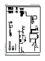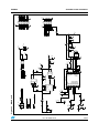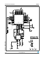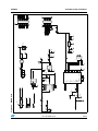
1
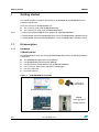
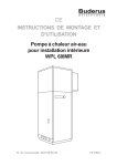
UM0894
User manual
STM32W-SK and STM32W-EXT starter and extension kits
for STM32W108xx microcontrollers
Introduction
The STM32W-SK and STM32W-EXT starter and extension kits are easy to use tools for the
STM32W108xx microcontrollers. This family of microcontrollers integrates a 32-bit ARM®
Cortex™-M3 microprocessor and a 2.4 GHz, IEEE 802.15.4-compliant transceiver. The kits
demonstrate how effectively the STM32W108xx can be used in real IEEE 802.15.4
applications. They are suitable for different types of wireless network scenarios such as:
●
Remote control and target networks (based on the ZigBee RF4CE protocol stack) used
for driving consumer devices such as TVs, set-top boxes, etc.
●
Point to point networks (based on a Simplified MAC library) used to address a basic
IEEE 802.15.4 communication. This configuration enables customers to develop any
protocol stack of their choice.
The STM32W108xx kits provide demonstration applications and documentation which serve
as a reference for creating your own applications and re-programming the STM32W108xx
microcontroller. You can run the STM32W108xx kits in several ways (remote control/target
and point-to-point applications), using the dedicated software libraries (ZigBee RF4CE, and
Simplified MAC), as well as a third-party IDE and C compiler (IAR).
Moreover, the STM32W108xx kits provide a set of APIs which allow you to use the kit
platform capabilities such as LEDs and serial communication channels (virtual COM
through USB).
In this manual, you can find information about:
Note:
●
The STM32W108xx kits components
●
How to install the related hardware and software trees
1
The term “application board” refers to the MB851 and MB954 platforms.
2
For more information, visit the STM32W 32-bit RF microcontroller webpages at
www.st.com/stm32w.
This web page provides full access to all the STM32W108xx resources (kits, software
packages and documents).
Table 1 lists the evaluation tools concerned by this user manual.
Table 1.
Applicable tools
Type
Evaluation tools
August 2012
Applicable tools
STM32W-SK and STM32W-EXT starter and extension kits
Doc ID 16999 Rev 6
1/45
www.st.com
Contents
UM0894
Contents
1
Getting started . . . . . . . . . . . . . . . . . . . . . . . . . . . . . . . . . . . . . . . . . . . . . . 6
1.1
Kit description . . . . . . . . . . . . . . . . . . . . . . . . . . . . . . . . . . . . . . . . . . . . . . . 6
1.1.1
1.2
Revision numbers of STM32W108xx starter and extension kit boards . . . 8
1.3
MB850 hardware description . . . . . . . . . . . . . . . . . . . . . . . . . . . . . . . . . . . 8
1.4
1.5
1.6
2/45
Hardware . . . . . . . . . . . . . . . . . . . . . . . . . . . . . . . . . . . . . . . . . . . . . . . . . 6
1.3.1
MB850 resources . . . . . . . . . . . . . . . . . . . . . . . . . . . . . . . . . . . . . . . . . . . 8
1.3.2
MB850 connectors . . . . . . . . . . . . . . . . . . . . . . . . . . . . . . . . . . . . . . . . . . 9
1.3.3
MB850 connectors: JP1 pins . . . . . . . . . . . . . . . . . . . . . . . . . . . . . . . . . . 9
1.3.4
MB850 connectors: JP2 pins . . . . . . . . . . . . . . . . . . . . . . . . . . . . . . . . . . 9
1.3.5
MB850 jumper configuration . . . . . . . . . . . . . . . . . . . . . . . . . . . . . . . . . 10
1.3.6
MB850 PC interface chip . . . . . . . . . . . . . . . . . . . . . . . . . . . . . . . . . . . . 10
1.3.7
MB850 battery holder . . . . . . . . . . . . . . . . . . . . . . . . . . . . . . . . . . . . . . 10
MB951 hardware description . . . . . . . . . . . . . . . . . . . . . . . . . . . . . . . . . . 10
1.4.1
MB951 resources . . . . . . . . . . . . . . . . . . . . . . . . . . . . . . . . . . . . . . . . . . 10
1.4.2
MB951 connectors . . . . . . . . . . . . . . . . . . . . . . . . . . . . . . . . . . . . . . . . . 10
1.4.3
MB951 jumpers configuration . . . . . . . . . . . . . . . . . . . . . . . . . . . . . . . . 11
1.4.4
MB951 PC Interface chip . . . . . . . . . . . . . . . . . . . . . . . . . . . . . . . . . . . . 11
1.4.5
MB951 battery holder . . . . . . . . . . . . . . . . . . . . . . . . . . . . . . . . . . . . . . 11
MB851 hardware description . . . . . . . . . . . . . . . . . . . . . . . . . . . . . . . . . . 11
1.5.1
MB851 resources . . . . . . . . . . . . . . . . . . . . . . . . . . . . . . . . . . . . . . . . . . 11
1.5.2
MB851 connectors . . . . . . . . . . . . . . . . . . . . . . . . . . . . . . . . . . . . . . . . . 12
1.5.3
MB851 connectors: P1 pins . . . . . . . . . . . . . . . . . . . . . . . . . . . . . . . . . . 12
1.5.4
MB851 connectors: P4 pins . . . . . . . . . . . . . . . . . . . . . . . . . . . . . . . . . . 13
1.5.5
MB851 jumper configuration . . . . . . . . . . . . . . . . . . . . . . . . . . . . . . . . . 14
1.5.6
MB851 PC interface chip . . . . . . . . . . . . . . . . . . . . . . . . . . . . . . . . . . . . 14
1.5.7
MB851 battery holder . . . . . . . . . . . . . . . . . . . . . . . . . . . . . . . . . . . . . . 14
MB954 hardware description . . . . . . . . . . . . . . . . . . . . . . . . . . . . . . . . . . 14
1.6.1
MB954 resources . . . . . . . . . . . . . . . . . . . . . . . . . . . . . . . . . . . . . . . . . . 14
1.6.2
MB954 connectors . . . . . . . . . . . . . . . . . . . . . . . . . . . . . . . . . . . . . . . . . 15
1.6.3
MB954 connectors: P1 pins . . . . . . . . . . . . . . . . . . . . . . . . . . . . . . . . . . 15
1.6.4
MB954 connectors: P4 pins . . . . . . . . . . . . . . . . . . . . . . . . . . . . . . . . . . 16
1.6.5
MB954 jumper configuration . . . . . . . . . . . . . . . . . . . . . . . . . . . . . . . . . 17
1.6.6
MB954 PC interface chip . . . . . . . . . . . . . . . . . . . . . . . . . . . . . . . . . . . . 17
1.6.7
MB954 battery holder . . . . . . . . . . . . . . . . . . . . . . . . . . . . . . . . . . . . . . 17
Doc ID 16999 Rev 6
UM0894
2
Contents
1.7
Software . . . . . . . . . . . . . . . . . . . . . . . . . . . . . . . . . . . . . . . . . . . . . . . . . . 17
1.8
Documentation . . . . . . . . . . . . . . . . . . . . . . . . . . . . . . . . . . . . . . . . . . . . . 18
1.9
Software libraries and demonstration applications . . . . . . . . . . . . . . . . . . 18
1.10
Kit set-up . . . . . . . . . . . . . . . . . . . . . . . . . . . . . . . . . . . . . . . . . . . . . . . . . 18
Powering on the boards . . . . . . . . . . . . . . . . . . . . . . . . . . . . . . . . . . . . . 18
1.10.2
Installing drivers for USB virtual COM . . . . . . . . . . . . . . . . . . . . . . . . . . 18
1.10.3
Setting up the application serial communication channel . . . . . . . . . . . 19
Running the STM32W108xx kits . . . . . . . . . . . . . . . . . . . . . . . . . . . . . . 20
2.1
Installing the STM32W108xx kit software tree . . . . . . . . . . . . . . . . . . . . . 20
2.2
Remote control and virtual TV (based on RF4CE library) . . . . . . . . . . . . 20
2.3
3
1.10.1
2.2.1
Run the remote control (RC) and virtual TV applications . . . . . . . . . . . 21
2.2.2
Use the remote control (RC) and virtual TV applications . . . . . . . . . . . . 22
2.2.3
Use the virtual remote control (RC) and virtual TV applications . . . . . . 22
Basic star network (based on SimpleMAC library) . . . . . . . . . . . . . . . . . . 23
2.3.1
Run preloaded sample appl. on STM32-Primer2, MB850 platforms
(only for STM32W108B-SK) . . . . . . . . . . . . . . . . . . . . . . . . . . . . . . . . . 23
2.3.2
Run the sample planet application on the application board . . . . . . . . . 24
2.3.3
Set up a star network using STM32-Primer2, MB850 platforms . . . . . . 24
2.3.4
SimpleMAC Sun PC applet (based on SimpleMAC library) . . . . . . . . . . 25
2.3.5
Run the SimpleMAC Sun PC applet . . . . . . . . . . . . . . . . . . . . . . . . . . . 25
2.3.6
Build, download and run the sample planet application on
the application board . . . . . . . . . . . . . . . . . . . . . . . . . . . . . . . . . . . . . . . 27
2.3.7
Set up a star network using SimpleMAC Sun PC applet . . . . . . . . . . . . 28
STM32W108xx kits utilities and software tools . . . . . . . . . . . . . . . . . . 30
3.1
stm32w_flasher utility . . . . . . . . . . . . . . . . . . . . . . . . . . . . . . . . . . . . . . . . 30
3.2
Network analyzer . . . . . . . . . . . . . . . . . . . . . . . . . . . . . . . . . . . . . . . . . . . 30
3.2.1
3.3
Perytons . . . . . . . . . . . . . . . . . . . . . . . . . . . . . . . . . . . . . . . . . . . . . . . . . 30
IAR Embedded Workbench® for ARM . . . . . . . . . . . . . . . . . . . . . . . . . . . 31
4
List of acronyms . . . . . . . . . . . . . . . . . . . . . . . . . . . . . . . . . . . . . . . . . . . 32
5
Available board schematics . . . . . . . . . . . . . . . . . . . . . . . . . . . . . . . . . . 33
6
Revision history . . . . . . . . . . . . . . . . . . . . . . . . . . . . . . . . . . . . . . . . . . . 44
Doc ID 16999 Rev 6
3/45
List of tables
UM0894
List of tables
Table 1.
Table 2.
Table 3.
Table 4.
Table 5.
Table 6.
Table 7.
Table 8.
Table 9.
Table 10.
Table 11.
Table 12.
Table 13.
Table 14.
Table 15.
Table 16.
Table 17.
Table 18.
Table 19.
Table 20.
Table 21.
Table 22.
Table 23.
Table 24.
Table 25.
Table 26.
4/45
Applicable products and tools . . . . . . . . . . . . . . . . . . . . . . . . . . . . . . . . . . . . . . . . . . . . . . . . 1
Boards revision numbers . . . . . . . . . . . . . . . . . . . . . . . . . . . . . . . . . . . . . . . . . . . . . . . . . . . 8
MB850 connectors . . . . . . . . . . . . . . . . . . . . . . . . . . . . . . . . . . . . . . . . . . . . . . . . . . . . . . . . 9
MB850 connectors: JP1 pins . . . . . . . . . . . . . . . . . . . . . . . . . . . . . . . . . . . . . . . . . . . . . . . . 9
MB850 connectors: JP2 pins . . . . . . . . . . . . . . . . . . . . . . . . . . . . . . . . . . . . . . . . . . . . . . . . 9
MB951 board resources to develop applications and connection . . . . . . . . . . . . . . . . . . . 10
MB951 board connectors. . . . . . . . . . . . . . . . . . . . . . . . . . . . . . . . . . . . . . . . . . . . . . . . . . 10
PC interface chip . . . . . . . . . . . . . . . . . . . . . . . . . . . . . . . . . . . . . . . . . . . . . . . . . . . . . . . . 11
MB851 resources . . . . . . . . . . . . . . . . . . . . . . . . . . . . . . . . . . . . . . . . . . . . . . . . . . . . . . . . 11
MB851 connectors . . . . . . . . . . . . . . . . . . . . . . . . . . . . . . . . . . . . . . . . . . . . . . . . . . . . . . . 12
MB851 connectors: P1 pins . . . . . . . . . . . . . . . . . . . . . . . . . . . . . . . . . . . . . . . . . . . . . . . . 12
MB851 connectors: P4 pins . . . . . . . . . . . . . . . . . . . . . . . . . . . . . . . . . . . . . . . . . . . . . . . . 13
MB851 jumper configuration . . . . . . . . . . . . . . . . . . . . . . . . . . . . . . . . . . . . . . . . . . . . . . . . 14
MB851 PC Interface chip . . . . . . . . . . . . . . . . . . . . . . . . . . . . . . . . . . . . . . . . . . . . . . . . . . 14
MB851 battery holder . . . . . . . . . . . . . . . . . . . . . . . . . . . . . . . . . . . . . . . . . . . . . . . . . . . . . 14
MB954 resources . . . . . . . . . . . . . . . . . . . . . . . . . . . . . . . . . . . . . . . . . . . . . . . . . . . . . . . . 14
MB954 connectors . . . . . . . . . . . . . . . . . . . . . . . . . . . . . . . . . . . . . . . . . . . . . . . . . . . . . . . 15
MB954 connectors: P1 pins . . . . . . . . . . . . . . . . . . . . . . . . . . . . . . . . . . . . . . . . . . . . . . . . 15
MB954 connectors: P4 pins . . . . . . . . . . . . . . . . . . . . . . . . . . . . . . . . . . . . . . . . . . . . . . . . 16
MB954 jumper configuration . . . . . . . . . . . . . . . . . . . . . . . . . . . . . . . . . . . . . . . . . . . . . . . . 17
MB954 PC interface chip . . . . . . . . . . . . . . . . . . . . . . . . . . . . . . . . . . . . . . . . . . . . . . . . . . 17
MB954 battery holder . . . . . . . . . . . . . . . . . . . . . . . . . . . . . . . . . . . . . . . . . . . . . . . . . . . . . 17
Definition of LCD screen symbols (SimpleMAC sample application) . . . . . . . . . . . . . . . . . 25
SimpleMAC Sun PC applet command options . . . . . . . . . . . . . . . . . . . . . . . . . . . . . . . . . . 27
List of acronyms used in the document . . . . . . . . . . . . . . . . . . . . . . . . . . . . . . . . . . . . . . . 32
Document revision history . . . . . . . . . . . . . . . . . . . . . . . . . . . . . . . . . . . . . . . . . . . . . . . . . 44
Doc ID 16999 Rev 6
UM0894
List of figures
List of figures
Figure 1.
Figure 2.
Figure 3.
Figure 4.
Figure 5.
Figure 6.
Figure 7.
Figure 8.
Figure 9.
Figure 10.
Figure 11.
Figure 12.
Figure 13.
Figure 14.
Figure 15.
Figure 16.
Figure 17.
Figure 18.
Figure 19.
Figure 20.
Figure 21.
Figure 22.
Figure 23.
Figure 24.
Figure 25.
Figure 26.
Figure 27.
Figure 28.
STM32W108B-SK starter kit. . . . . . . . . . . . . . . . . . . . . . . . . . . . . . . . . . . . . . . . . . . . . . . . . 7
STM32W108C-SK starter kit . . . . . . . . . . . . . . . . . . . . . . . . . . . . . . . . . . . . . . . . . . . . . . . . 7
MB851 application board . . . . . . . . . . . . . . . . . . . . . . . . . . . . . . . . . . . . . . . . . . . . . . . . . . . 8
MB954 application board with a power amplifier . . . . . . . . . . . . . . . . . . . . . . . . . . . . . . . . . 8
RF4CETV PC applet. . . . . . . . . . . . . . . . . . . . . . . . . . . . . . . . . . . . . . . . . . . . . . . . . . . . . . 21
RF4CE RC application driving the ST Virtual TV PC applet . . . . . . . . . . . . . . . . . . . . . . . . 22
RF4CERC PC applet . . . . . . . . . . . . . . . . . . . . . . . . . . . . . . . . . . . . . . . . . . . . . . . . . . . . . 23
STM32-Primer2 sun node. . . . . . . . . . . . . . . . . . . . . . . . . . . . . . . . . . . . . . . . . . . . . . . . . . 24
Planet device joined to the network . . . . . . . . . . . . . . . . . . . . . . . . . . . . . . . . . . . . . . . . . . 24
Planet sends data to the sun . . . . . . . . . . . . . . . . . . . . . . . . . . . . . . . . . . . . . . . . . . . . . . . 24
Sun node with 5 planets . . . . . . . . . . . . . . . . . . . . . . . . . . . . . . . . . . . . . . . . . . . . . . . . . . . 25
Network down . . . . . . . . . . . . . . . . . . . . . . . . . . . . . . . . . . . . . . . . . . . . . . . . . . . . . . . . . . 25
SimpleMAC Sun PC applet flash image check . . . . . . . . . . . . . . . . . . . . . . . . . . . . . . . . . . 26
SimpleMAC Sun node forming an IEEE 802.15.4 network. . . . . . . . . . . . . . . . . . . . . . . . . 27
Planet device joined to the network . . . . . . . . . . . . . . . . . . . . . . . . . . . . . . . . . . . . . . . . . . 28
Planet sends data to the sun . . . . . . . . . . . . . . . . . . . . . . . . . . . . . . . . . . . . . . . . . . . . . . . 28
Sun node with 5 planets . . . . . . . . . . . . . . . . . . . . . . . . . . . . . . . . . . . . . . . . . . . . . . . . . . . 29
MB850 rev. A . . . . . . . . . . . . . . . . . . . . . . . . . . . . . . . . . . . . . . . . . . . . . . . . . . . . . . . . . . . 33
MB851 module . . . . . . . . . . . . . . . . . . . . . . . . . . . . . . . . . . . . . . . . . . . . . . . . . . . . . . . . . . 34
MB851 rev. A . . . . . . . . . . . . . . . . . . . . . . . . . . . . . . . . . . . . . . . . . . . . . . . . . . . . . . . . . . . 35
MB851 rev. B . . . . . . . . . . . . . . . . . . . . . . . . . . . . . . . . . . . . . . . . . . . . . . . . . . . . . . . . . . . 36
MB851 rev. C . . . . . . . . . . . . . . . . . . . . . . . . . . . . . . . . . . . . . . . . . . . . . . . . . . . . . . . . . . . 37
MB851 rev. D . . . . . . . . . . . . . . . . . . . . . . . . . . . . . . . . . . . . . . . . . . . . . . . . . . . . . . . . . . . 38
MB954 module . . . . . . . . . . . . . . . . . . . . . . . . . . . . . . . . . . . . . . . . . . . . . . . . . . . . . . . . . . 39
MB954 rev. A . . . . . . . . . . . . . . . . . . . . . . . . . . . . . . . . . . . . . . . . . . . . . . . . . . . . . . . . . . . 40
MB954 rev. B . . . . . . . . . . . . . . . . . . . . . . . . . . . . . . . . . . . . . . . . . . . . . . . . . . . . . . . . . . . 41
MB954 rev. C . . . . . . . . . . . . . . . . . . . . . . . . . . . . . . . . . . . . . . . . . . . . . . . . . . . . . . . . . . . 42
MB951 rev. B . . . . . . . . . . . . . . . . . . . . . . . . . . . . . . . . . . . . . . . . . . . . . . . . . . . . . . . . . . . 43
Doc ID 16999 Rev 6
5/45
Getting started
1
UM0894
Getting started
This section provides a complete description of the STM32W-SK and STM32W-EXT kit’s
hardware and software.
There are two types of STM32W108xx kits:
Note:
●
The starter kit (order code: STM32W108C-SK)
●
The extension kit (order code: STM32W108C-KEXT)
1. Order code STM32W108B-KEXT is replaced by STM32W108C-KEXT.
2. STM32W108C-SK and STM32W108C-KEXT contain STM32W108CC (256-Kbyte Flash).
3. STM32W108B-SK and STM32W108B-KEXT contain STM32W108xB (128-Kbyte Flash).
1.1
Kit description
1.1.1
Hardware
STM32W108B-SK
The STM32W108xx starter kit package (STM32W108B-SK) contains the following hardware
components:
●
Two STM32W108 application boards (MB851)
●
One STM32W108 extension board (MB850)
●
One Raisonance STM32-Primer2 tool (STM3210E-PRIMER)
●
One J-Link Lite JTAG Flash programmer and debugger
●
One mini USB cable
●
Four AAA batteries
Figure 1.
STM32W108B-SK starter kit
J-Link Lite +
IAR compiler
Network Analyzer (Perytons)
MB850
extension board
+
STM32-Primer2
MB851 application board x2
6/45
Doc ID 16999 Rev 6
UM0894
Getting started
STM32W108C-SK
The STM32W108xx starter kit package (STM32W108C-SK) contains the following
hardware components:
●
Two STM32W108 application boards (MB851)
●
One STM32W108 USB Dongle (MB951)
●
One J-Link Lite JTAG Flash programmer and debugger
●
One mini USB cable
●
Four AAA batteries
Figure 2.
STM32W108C-SK starter kit
J-Link Lite +
IAR compiler
Network analyzer (Perytons)
MB951
USB dongle
MB851 application board x2
Doc ID 16999 Rev 6
7/45
Getting started
UM0894
STM32W-EXT
The extension kit package contains two STM32W108 application boards (MB851) and two
STM32W108 application boards with a power amplifier (MB954).
Figure 3.
MB851 application board
Figure 4.
MB954 application board with a
power amplifier
Note:
For information concerning the STM32W108xx application boards, refer to the STM32W 32bit RF microcontroller webpages at www.st.com/stm32w.
1.2
Revision numbers of STM32W108xx starter and extension kit
boards
Table 2 details the STM32W108xB starter and extension kit board revision numbers versus
those of the STM32W108CC.
Table 2.
.
Boards revision numbers
STM32W108xB (128K Flash)
MB851
Revision A, B, C
Revision D
MB954
Revision A, B
Revision C
MB951
NA
Revision B
MB850
Revision A
NA
NA = Not applicable
1.3
MB850 hardware description
1.3.1
MB850 resources
None
8/45
STM32W108CC (256K Flash)
Doc ID 16999 Rev 6
UM0894
1.3.2
Getting started
MB850 connectors
Table 3 lists the connectors available in the MB850 board and their functions.
Table 3.
1.3.3
Type
Label
Function
Header 6H
JP1
SWD debug
Header 10X2
JP2
Connector to Primer2 board
MB850 connectors: JP1 pins
Table 4.
1.3.4
MB850 connectors
MB850 connectors: JP1 pins
Pin number
GPIO/ Function
1
+2V8
2
GND
3
PC0/JRST
4
SWCLK/JTCK
5
PC4/SWDIO/JTMS
6
nRST
MB850 connectors: JP2 pins
Table 5.
MB850 connectors: JP2 pins
Pin number
GPIO/ Function
1
+2V8
2
GND
3
NC
4
NC
5
PA0
6
PA1
7
PA2
8
PA3
9
NC
10
NC
11
nRST
12
PA5
13
NC
14
PB4
15
PB3
Doc ID 16999 Rev 6
9/45
Getting started
Table 5.
1.3.5
UM0894
MB850 connectors: JP2 pins (continued)
Pin number
GPIO/ Function
16
PB2
17
NC
18
PB1
19
NC
20
GND
MB850 jumper configuration
None
1.3.6
MB850 PC interface chip
None
1.3.7
MB850 battery holder
None
1.4
MB951 hardware description
1.4.1
MB951 resources
Table 6 lists the resources available in the MB951 board to develop applications and their
connection with STM32W108 pins.
Table 6.
MB951 board resources to develop applications and connection
Rev B
Type
Label
Part
STM32W108 pin
Button
S1
PA3
LED
D1
PA5
LED
D3
PA0
Note:
MB951 revision A is not used in any of the STM32W108xx starter and extension kits.
1.4.2
MB951 connectors
Table 7 lists the connectors available in the MB951 board and their functions.
Table 7.
.
10/45
MB951 board connectors
Type
Label
Function
USB
P1
PC I/O
Doc ID 16999 Rev 6
UM0894
1.4.3
Getting started
MB951 jumpers configuration
None
1.4.4
MB951 PC Interface chip
Table 8 lists the PC interface chip available in the MB951 board to allow I/O interface to the
STM32W108.
Table 8.
1.4.5
PC interface chip
Type
Part
PC I/O interface
STM32F103TBU6
MB951 battery holder
None
1.5
MB851 hardware description
1.5.1
MB851 resources
Table 9 lists the resources available in the MB851 board to develop applications and their
connection with STM32W108 pins.
Table 9.
MB851 resources
Rev A
Type
Label
Rev B
Rev C, D
Part
STM32W108 pin
Button
RST1
Button
S1
I²C EEPROM
U4
LED
PA7
PA7
PB3
NA
NA
PA1, PA2
D1
PB6
PB6
PA5
LED
D3
PB5
PB5
PA0
LED
D5
Infrared LED
PB4
PB4
PB4
Mems
U2
LIS302
PA1, PA2
PA1, PA2
PA1, PA2
Temperature
sensor
U3
STLM20
PB7
PB7
PA4
M24C64MW1
128 KBytes
Doc ID 16999 Rev 6
11/45
Getting started
1.5.2
UM0894
MB851 connectors
Table 10 lists the connectors available in the MB851 board and their functions.
Table 10.
1.5.3
Type
Label
Function
Mini USB
J2
PC I/O
Header, 14-pin, dual row male
P1
GPIO access
Header, 10-pin, dual row male
P4
Standard JTAG debug
MB851 connectors: P1 pins
Table 11.
12/45
MB851 connectors
MB851 connectors: P1 pins
Pin number
GPIO function
1
+VBRD
2
PC5
3
nRST
4
PA7
5
PB3
6
PB4
7
PA0
8
PA1
9
PA2
10
PA4
11
PA3
12
PA6
13
PA5
14
GND
15
PB1
16
PB2
17
JTCK
18
PC2
19
PC3
20
PC4
21
GND
22
GND
23
PB0
24
PC1
Doc ID 16999 Rev 6
UM0894
Getting started
Table 11.
1.5.4
MB851 connectors: P1 pins (continued)
Pin number
GPIO function
25
PC0
26
PB7
27
PB6
28
PB5
MB851 connectors: P4 pins
Table 12.
MB851 connectors: P4 pins
Pin number
GPIO function
1
+VBRD
2
+VBRD
3
PC0
4
GND
5
PC3
6
GND
7
PC4
8
GND
9
JTCK
10
GND
11
GND
12
GND
13
PC2
14
GND
15
nRST
16
GND
17
GND
18
GND
19
+VJTAG
20
GND
Doc ID 16999 Rev 6
13/45
Getting started
1.5.5
UM0894
MB851 jumper configuration
Table 13 lists the jumpers configurations on the MB851 board.
Table 13.
MB851 jumper configuration
Label
Configuration
JP1
Power Mems, temperature sensor and
infrared LED
1-2: battery powered
P2
2-3: reserved
3-4: USB or JTAG powered
1.5.6
MB851 PC interface chip
Table 14 lists the PC interface chip available in the MB851 board to allow I/O interface to the
STM32W108.
Table 14.
1.5.7
MB851 PC Interface chip
Revision
Type
Part
Rev. A
PC I/O
FTDI FT232R
Rev. B
PC I/O
FTDI FT232R
Rev. C, D
PC I/O
STM32F103TBU6
MB851 battery holder
Table 15.
MB851 battery holder
Type
Label
2x AAA battery holder
BT1
1.6
MB954 hardware description
1.6.1
MB954 resources
Table 16 lists the resources available in the MB954 board to develop applications and their
connection with STM32W108 pins.
Table 16.
Type
14/45
MB954 resources
Label
Button
RST1
Button
S1
Rev. A
Rev. B, C
GPIO
GPIO
PB3
PB3
Part
Doc ID 16999 Rev 6
UM0894
Getting started
Table 16.
MB954 resources (continued)
Type
Label
I²C EEPROM
M24C64MW1
128 KBytes
U4
LED
1.6.2
Rev. A
Rev. B, C
GPIO
GPIO
Not fitted
PA2
PA5
PA5
PA0
PA0
Part
LED
D3
LED
D5
Infrared LED
PB4
PB4
Mems
U2
LIS302
PA1, PA2
PA1, PA2
Temperature
sensor
U3
STLM20
PA4
PA4
MB954 connectors
Table 17 lists the connectors available in the MB954 board and their functions.
Table 17.
1.6.3
MB954 connectors
Type
Label
Function
Mini USB
J2
PC I/O
Header, 14-pin, dual row male
P1
GPIO access
Debug connector
P4
Standard JTAG debug
MB954 connectors: P1 pins
Table 18.
MB954 connectors: P1 pins
Name
GPIO function
1
+VBRD
2
PC5
3
nRST
4
PA7
5
PB3
6
PB4
7
PA0
8
PA1
9
PA2
10
PA4
11
PA3
12
PA6
13
PA5
14
GND
15
PB1
Doc ID 16999 Rev 6
15/45
Getting started
Table 18.
UM0894
MB954 connectors: P1 pins (continued)
Name
1.6.4
16
PB2
17
JTCK
18
PC2
19
PC3
20
PC4
21
GND
22
GND
23
PB0
24
PC1
25
PC0
26
PB7
27
PB6
28
PB5
MB954 connectors: P4 pins
Table 19.
16/45
GPIO function
MB954 connectors: P4 pins
Name
GPIO function
1
+VBRD
2
+VBRD
3
PC0
4
GND
5
PC3
6
GND
7
PC4
8
GND
9
JTCK
10
GND
11
GND
12
GND
13
PC2
14
GND
15
nRST
16
GND
17
GND
18
GND
19
+VJTAG
20
GND
Doc ID 16999 Rev 6
UM0894
1.6.5
Getting started
MB954 jumper configuration
Table 20 lists the jumpers configurations in the MB954 board.
Table 20.
MB954 jumper configuration
Label
Configuration
JP1
Power Mems, temperature sensor and infrared LED
1-2: battery powered
P2
2-3: reserved
3-4: USB or JTAG powered
1.6.6
MB954 PC interface chip
Table 21 lists the PC interface chip available in the MB954 board to allow I/O interface to the
STM32W108.
Table 21.
1.6.7
Revision
Type
Part
Rev. A
PC I/O
FTDI FT232R
Rev. B, C
PC I/O
STM32F103TBU6
MB954 battery holder
Table 22.
1.7
MB954 PC interface chip
MB954 battery holder
Type
Part
2x AAA battery holder
BT1
Software
STM32W-SK
The starter kit package contains the following software components:
Note:
●
One CD-ROM including PerytonsTM network analyzer.
●
One CD-ROM including the IARTM Limited 30-days Evaluation Compiler.
STM32W108B-SK also contains one CD-ROM including the RaisonanceTM Development
Suite for the STM32-Primer2.
STM32W-EXT
No CDs are delivered with the extension kit package.
Doc ID 16999 Rev 6
17/45
Getting started
1.8
UM0894
Documentation
The starter kit package STM32W-SK contains the following documentation components:
●
Note:
STM32W108 starter kit welcome letter which briefly describes the kits targets and
components.
STM32W108B-SK also contains Raisonance STM32-Primer2 welcome letter.
The extension kit package STM32W-EXT contains an STM32W108 extension kit welcome
letter which briefly describes the kits targets and components.
1.9
Software libraries and demonstration applications
The STM32W108xx Starter and Extension Kit boards supports the following RF Software
libraries packages:
●
ST ZigBee RF4CE software library and ZRC, ZID application profiles with
demonstration applications for controlling an RF4CE compliant TV using an RF4CE
compliant remote control and a RF4CE mouse, keyboard, ...
●
ST SimpleMAC software library and demonstration applications targeting point-to-point
communication scenarios based on the IEEE 802.15.4 protocol.
For a detailed description of each software package, refer to the related documentation.
Note:
Please check for the most recent RF library package versions on the STM32W 32-bit RF
MCUs Internet webpages at www.st.com/stm32w.
1.10
Kit set-up
1.10.1
Powering on the boards
Each application board can be powered as follows:
●
Via batteries (fit 1-2 on the P2 jumper)
●
Via USB or JTAG (fit 5-6 on the P2 jumper)
Note:
1. The jumper position 3-4 is reserved for internal usage.
2. To enable the application board temperature, MEMS and infrared sensors, fit jumper JP1.
3. MB951 USB dongle can be powered only by connecting it to a PC USB port.
The MB850 extension board is designed as an IEEE 802.15.4 application-specific
daughterboard. It must be connected to the STM32-Primer2 extension connector to be
powered through the STM32-Primer2. The MB850 should be connected with the
STM32W108 visible.
1.10.2
Installing drivers for USB virtual COM
In order to use the serial communication channel on an application board, a driver for the
FTDI USB<-> Serial converter or a Virtual COM port driver for an STM32F103xx must be
installed. The correct driver to install is based on the application board revision number.
The following application boards requires the driver FTDI USB <-> Serial converter:
●
MB851 Rev A
●
MB851 Rev B
●
MB954 Rev A
18/45
Doc ID 16999 Rev 6
UM0894
Getting started
The related drivers can be downloaded from the FTDI website at
www.ftdichip.com/Drivers/D2XX.htm.
All other application boards require the STMicroelectronics Virtual COM port driver which is
provided within each RF software library package.
1.10.3
Setting up the application serial communication channel
To get full access to all the available commands, some demonstration applications may
require that the application board is interfaced with the user through a serial communication
channel (virtual COM through USB). To set a serial communication channel for the
application board, follow these steps:
1. Where applicable, fit the application board jumper P2 on position 5-6 (power via USB).
2. Connect a mini USB cable to the application board mini-USB connector and to a PC
USB port.
3. Right-click on My Computer, select Manage, Device Manager, and open Ports (COM
& LPT) to display the related USB COMx port.
4. Open a hyper terminal on the corresponding USB virtual COMx port with the following
configuration:
–
Bit rate: 115200
–
Data bits: 8
–
Parity: None
–
Stop bits: 1
–
Flow control: None
The STM32-Primer2 and MB850 demonstration applications use the STM32-Primer2
resources (LCD, joystick with button, touch screen display) as I/O communication channels.
Doc ID 16999 Rev 6
19/45
Running the STM32W108xx kits
2
UM0894
Running the STM32W108xx kits
STM32W-SK
In the STM32W-SK starter kit (STM32W108B-SK), the following applications are
preprogrammed:
●
●
Two CircleOs applications preloaded in the STM32-Primer2:
–
ZigBee RF4CE RC application
–
SimpleMAC sun sample application
One Perytons capture firmware (application board labeled as “Analyzer”)
In the STM32W-SK starter kit (STM32W108C-SK), the following applications are
preprogrammed:
●
One SimpleMAC planet application (application board labeled as "Planet")
●
One Perytons capture firmware (application board labeled as “Analyzer”)
●
A USB dongle with SimpleMAC planet application
You can also start a packet capture session using the Perytons analyzer (see Section 3.2:
Network analyzer for more details).
STM32W-EXT
In the STM32W-EXT extension kit, all four boards are preprogrammed with SimpleMAC
planet firmware (application board labeled as "Planet").
Using these boards, you can extend the sun, planet point to point network with other four
planet nodes.
2.1
Installing the STM32W108xx kit software tree
To install the specific kit software tree, download the related RF software library package
from the STM32W 32-bit RF MCUs Internet web pages.
2.2
Remote control and virtual TV (based on RF4CE library)
This section shows how to control a ZigBee RF4CE-compliant TV target using an RF4CEcompliant remote control. The demonstration application is run using the STM32-Primer2
and MB850 as a remote control and a PC applet for emulating a TV on your PC.
The RF4CETV PC applet implements a virtual TV supporting the following features:
Note:
20/45
●
12 channels, playing video from files
●
Volume control
●
Mute
●
Channel change
●
Play/Pause
●
Pair button
●
Device information
STM32- Primer2 and MB850 are available only with STM32W108B-SK kit.
Doc ID 16999 Rev 6
UM0894
2.2.1
Running the STM32W108xx kits
Run the remote control (RC) and virtual TV applications
The STM32-Primer2 tool provided with the STM32W-SK starter kit (only STM32W108B-SK)
is delivered with the RC application. This application automatically configures the connected
MB850 extension board with the related ZigBee RF4CE RC application.
The application board is automatically configured when launching the RF4CETV PC applet.
To run the RC and TV applications on the STM32 Primer2, MB850 and application board
platforms, the following steps are required:
1.
Connect the MB850 to the extension connector of the STM32-Primer2 tool.
2.
Power on your STM32-Primer2.
3.
Press the joystick button to launch the Main Menu and select Applic.->RF4CE RC.
If everything is properly done, the LCD screen displays a set of RF4CE RC commands.
4.
Connect the application board to the PC using a mini USB cable with P2 fitted in
position 5-6 (power from USB). A virtual COM port should appear in the Windows
Device Manager.
5.
From Windows, launch the RF4CETV.exe PC applet. A PC applet GUI appears.
6.
Select the serial port matching the port assigned by the Windows Device Manager. If
the firmware on the application board is not present, the application uploads the
firmware through the serial port. Wait until LED D1 is on.
7.
Push the button
to start pairing with the RF4CE remote control. LED D1 starts
blinking quickly when the node is ready for pairing (for 30 sec.).
8.
On your STM32-Primer2, use the joystick to scroll between button pages until you find
the button
. Push the button to start pairing with the application board.
If everything is properly done, a message on your STM32-Primer2 screen and in the
RF4CETV applet informs you that the pairing process has been successful.
Figure 5.
RF4CETV PC applet
Doc ID 16999 Rev 6
21/45
Running the STM32W108xx kits
2.2.2
UM0894
Use the remote control (RC) and virtual TV applications
To send an RC command to the virtual TV, push the associated RC symbol on the STM32Primer2 touch sensing screen.
Figure 6.
RF4CE RC application driving the ST Virtual TV PC applet
Note:
For further information about the ST RF4CE demonstration applications, refer to the
STM32W108xx ZigBee RF4CE library user manual (UM0909).
2.2.3
Use the virtual remote control (RC) and virtual TV applications
The same demonstration application can be run using the ST virtual remote control (RC) PC
applet.
The RF4CERC PC applet implements a virtual RC supporting the following features:
●
Certain RC standard buttons
●
Volume control
●
Mute
●
Channel change
●
Pair button
●
Paired device information
Click on From Windows to launch the RF4CERC.exe PC applet. A PC applet GUI appears.
22/45
Doc ID 16999 Rev 6
UM0894
Running the STM32W108xx kits
Figure 7.
RF4CERC PC applet
Push the button
drive the virtual TV.
2.3
to start pairing with the ST Virtual TV and then use the RC buttons to
Basic star network (based on SimpleMAC library)
This section shows how to set up a star network supporting parent and child roles (called,
respectively, sun and planet).
2.3.1
Run preloaded sample appl. on STM32-Primer2, MB850 platforms (only
for STM32W108B-SK)
The STM32-Primer2 tool provided with the STM32W-SK starter kit is delivered with a
sample application (sun image). This application automatically configures the connected
MB850 extension board with the related sample application.
To run the sample application on the STM32-Primer2, MB850 platforms, follow these steps:
1.
Connect the MB850 to the extension connector of the STM32-Primer2 tool.
2.
Power on your STM32-Primer2.
3.
Press the joystick button to launch the main menu and select Applic.->SM SUN.
If everything is done properly, you get an LCD screen showing a light blue box in the
center. This blue box represents the sun node (a network has been created).
Doc ID 16999 Rev 6
23/45
Running the STM32W108xx kits
Figure 8.
4.
2.3.2
UM0894
STM32-Primer2 sun node
Press the button again to access the application main menu. This is the first level
option list. Options can be classified in two categories:
–
Options that provide information about the sun parameters (node information,
planets list)
–
Options that execute actions (leave network, quit)
Run the sample planet application on the application board
To download and run the sample planet application on an application board, use the related
IAR project provided within the SimpleMAC software library package following the
instructions described in Section 3.3: IAR Embedded Workbench® for ARM.
2.3.3
Set up a star network using STM32-Primer2, MB850 platforms
On the planet node, press button S1 to join the network formed by the STM32-Primer2 sun
node. Once joined, the planet LED D3 turns on and the planet node is displayed on the
STM32-Primer2’s LCD (as a green box with the related 2-byte short address underneath).
Figure 9.
Planet device joined to the network
When a planet device sends data to the sun device (at a periodic rate), a blue line
connecting the transmitting planet to the sun is displayed on the screen as well as the sent
application board VDD_PADS value (in mV).
Figure 10. Planet sends data to the sun
This identifies which planet is in transmission mode if there is more than one planet device
(up to 5 supported by the STM32-Primer2 sun application).
24/45
Doc ID 16999 Rev 6
UM0894
Running the STM32W108xx kits
Figure 11. Sun node with 5 planets
Figure 12. Network down
The following table summarizes the symbols appearing on the LCD screen and the
associated events.
Table 23.
Definition of LCD screen symbols (SimpleMAC sample application)
Symbol
Associated event
Blue line connecting planet to sun
Planet sends data to the sun (see Figure 10)
D
Network down (see Figure 12)
Note:
For further information about the SimpleMAC sample application, refer to STM32W108xx
SimpleMAC user manual - UM0893, available on the STM32W 32-bit RF microcontroller
webpages at www.st.com/stm32w.
2.3.4
SimpleMAC Sun PC applet (based on SimpleMAC library)
This section shows how to set up a star network supporting parent and child roles (called,
respectively, sun and planet) by using a PC applet targeting the SimpleMAC Sun
application.
The main functions of the SimpleMAC Sun PC applet are:
2.3.5
●
Sun node forms a IEEE 802.15.4 network
●
Give all information about the sun node (channel, pan ID, node ID, eui64, tx power, ...)
●
Handling planets nodes joining to the network
●
Handling planets node leaving the network once
●
Sun node leaves network
●
Sun node receives data from each joined planet node
Run the SimpleMAC Sun PC applet
The application board is automatically configured when launching the SimpleMAC Sun PC
applet.
Doc ID 16999 Rev 6
25/45
Running the STM32W108xx kits
UM0894
To run the SimpleMAC Sun PC applet on an application board, the following steps are
required:
1.
Connect the application board to the PC using a mini USB cable with P2 fitted in
position 5-6 (power from USB). A virtual COM port should appear in the Windows
Device Manager (or connect the USB dongle directly to a PC USB port).
2.
From Windows, launch the SimpleMAC Sun Application.exe PC applet. A PC applet
GUI appears.
3.
Select the serial port matching the port assigned by the Windows Device Manager. If
the firmware on the application board is not present, the application uploads the
firmware through the serial port.
Figure 13. SimpleMAC Sun PC applet flash image check
4.
26/45
Push the button
to let the sun node form a network. If everything is done properly,
you get the following picture:
Doc ID 16999 Rev 6
UM0894
Running the STM32W108xx kits
Figure 14. SimpleMAC Sun node forming an IEEE 802.15.4 network
The SimpleMAC Sun PC applet is also offering these command options:
Table 24.
SimpleMAC Sun PC applet command options
Command
Description
Display all information about the sun node
Display a table giving information about planets
It allows the sun node to leave the network
2.3.6
Build, download and run the sample planet application on the
application board
To build, download and run the sample planet application on an application board, use the
related IAR project provided within the SimpleMAC software library package following the
instructions described in Section 3.3: IAR Embedded Workbench® for ARM.
Doc ID 16999 Rev 6
27/45
Running the STM32W108xx kits
2.3.7
UM0894
Set up a star network using SimpleMAC Sun PC applet
On the planet node, press button S1 to join the network formed by the STM32W108xx sun
node. Once joined, the planet node is displayed on the SimpleMAC Sun PC applet.
Figure 15. Planet device joined to the network
When a planet device sends data to the sun device (at a periodic rate), a line connecting the
transmitting planet to the sun is displayed on the SimpleMAC Sun PC applet as well as the
sent application board VDD_PADS value (in mV).
Figure 16. Planet sends data to the sun
28/45
Doc ID 16999 Rev 6
UM0894
Running the STM32W108xx kits
This identifies which planet is in transmission mode if there is more than one planet device
(up to 5 supported by the SimpleMAC Sun PC applet).
Figure 17. Sun node with 5 planets
Note:
For further information about the SimpleMAC sample application, refer to the
STM32W108xx SimpleMAC user manual - UM0893, available on the STM32W 32-bit RF
microcontroller webpages at www.st.com/stm32w.
Doc ID 16999 Rev 6
29/45
STM32W108xx kits utilities and software tools
3
STM32W108xx kits utilities and software tools
3.1
stm32w_flasher utility
UM0894
The stm32w_flasher utility allows you to download a binary file into the STM32W108xx
application board. This utility comes with each RF software library package. To download a
binary image, follow these steps:
1.
Where applicable, fit the application board jumper P2 on position 5-6 (power via USB).
2.
Connect a mini USB cable to the application board mini-USB connector and to a PC
USB port.
3.
Using the mouse, right-click on My Computer, select Manage, Device Manager, and
open Ports (COM & LPT) to display the related USB COMx port.
4.
Open a DOS Window on your PC.
5.
Go to the utilities folder which comes after the installation process.
6.
Type the following command: stm32w_flasher –p <COMx> -r –f <file_name.bin/.s37>
where COMx is the virtual COM related to the connected application board, and
file_name.bin/.s37 is the application image to be downloaded.
Note:
You can also use the stm32w_flasher utility through the JTAG programmer for all the boards
which have a JTAG connector:
1. Fit the application board jumper P2 on position 5-6 (power via JTAG).
2. Plug the JTAG programmer to a PC USB port and to the board JTAG connector P4.
3. Open a DOS Window on your PC.
4. Go to the folder where the stm32w_flasher is located (tool or utility folder).
5. Type the following command: stm32w_flasher -f <file_name.bin/.s37> -r
3.2
Network analyzer
3.2.1
Perytons
To install the Perytons network analyzer, insert the related CD-ROM and follow the
installation instructions. To use the Perytons network analyzer, follow these steps:
1.
Application board labeled as “Analyzer“: fit jumper P2 on position 5-6 (power via USB)
and connect to a PC USB port.
2.
Open the Perytons tool (from Start, Programs).
3.
For instructions about how to start a packet capture session, refer to the documentation
on the Perytons CD-ROM.
When a packet capture session is ongoing, the application board LEDs behave as follows:
●
When data is sent to the PC, LED D1 flashes for a short period.
●
LED D3 is the heartbeat LED.
A prebuilt analyzer binary image for Perytons is provided with each RF software library
package.
30/45
Doc ID 16999 Rev 6
UM0894
3.3
STM32W108xx kits utilities and software tools
IAR Embedded Workbench® for ARM
To install the IAR Embedded Workbench® for ARM, follow these steps:
1.
Go to the Download section of the IAR website (www.iar.com) download section and
select a 30-day IAR version for ARM.
2.
Start the download procedure and receive a 30-day license.
3.
Insert the STM32W108 Starter Kit IAR CD-ROM and follow the installation instructions
using the 30-day licence from the IAR website.
To build the binary image of all the available demonstration applications using the IAR tool,
follow these steps:
1.
Open the IAR tool.
2.
From the File > Open > Workspace menu, open the *.eww IAR project related to the
demonstration application you are going to address.
3.
From the Project menu, select Rebuild All. A binary file is built under the project folder
specified in Project > Options > General Options Category > Output menu >
Executables/libraries item.
To download the built binary image on the application board, follow these steps:
Note:
1.
Connect the JTAG Flash programmer to the application board P4 connector and to a
PC USB port (through a USB cable).
2.
Power the application board through the JTAG: P2 jumper fitted on 5-6 position.
3.
From the Project menu, select Download and Debug. The binary image is downloaded
into the STM32W108xx Flash.
4.
From the Project menu, select Stop Debugging. The application is ready to run.
To use the J-Link Lite JTAG Flash programmer, you need to switch on the “power supply for
target” feature. The first time you plug the J-Link Lite on a PC USB port, follow these steps
(make sure that you have already installed the IAR Embedded Workbench):
1.
Open a DOS Window on your PC.
2.
Type jlink.
3.
Issue the command: power on perm.
Doc ID 16999 Rev 6
31/45
List of acronyms
4
List of acronyms
Table 25.
32/45
UM0894
List of acronyms used in the document
Term
Meaning
API
Application programming interfaces
ZRC
ZigBee Remote Control
ZID
ZigBee Input Device
MAC
Medium access control
PA
Power amplifier
RC
Remote control
RF
Radio frequency communication
USB
Universal serial bus
Doc ID 16999 Rev 6
33/45
nRST
+2V8
GND
1
2
3
4
5
6
7
8
9
10
11
12
13
14
15
16
17
18
19
ZIG MOD V1
GND
GND
VCC
VCC
nRST
PC5
PC6
PC7
PA7
PB3
PB4
PA0
PA1
GND
PA2
PA3
PA4
PA5
PA6
ZG1
GND
PB5
PB6
PB7
PC0
PC1
GND
PB0
PC4
GND
PC3
PC2
SWCLK
PB2
PB1
GND
ANT
GND
34
33
32
31
30
29
28
27
26
25
24
23
22
21
20
37
36
35
Available board schematics
Figure 18. MB850 rev. A
5
GND
Doc ID 16999 Rev 6
GPIO01
GPIO11
nRST
GPIO16
SWCLK
SWDIO
nRST
GPIO00
+2V8
+2V8
2
4
6
8
10
12
14
16
18
20
Header 10X2
1
3
5
7
9
11
13
15
17
19
JP2
Header 6H
1
2
3
4
5
6
JP1
GPIO05
GPIO12
GPIO10
GPIO09
GND
C2
10uF
+2V8
MS19569V1
C1
100nF
Available board schematics
UM0894
GND
0
0
0
0
C13
GND
MS1
GND GND 0
GND GND 0
GND GND 0
GND GND 0
MetalShield16mm
GND
220pF
L1
7.5nH C10
DNI
C8
GND
GND
C9
E1
AN0835
GND
X
J1
1
AGND2
1
A50
4
GND
2.2uF
C19
1R
R5
C16
+
+1V8
10nF
GND
GND
GND
1
PC5
C4
C12
8pF
GND
3
2
180K
(1%)
L2
3.3nH
470nF
GND
R1 10R
-
T1
WE748-421-245
1
4
5
2
FLT1
WE748-351-124
GND
C3
10nF 10nF 8pF
GND GND GND
C2
GND
10nF
C22
nRST
R6
10K
+VBRD
GND
GPIO21
1
1
nRST
12
11
10
9
8
7
6
5
4
3
2
DNI
24MHz
C6
18pF
GND
1uF
GND
C20
+1V2
C17
GND
PC7
PB5
+1V2
PC6
RSTB
GPIO21
VDDA
BIAS R
VDD IF
RF TX ALTN
RF TX ALTP
VDD RF
RF N
RF P
VDDA
VDDA
X1
R2
GND
C5
18pF
48
OSCA
1
C1
47
OSCB
GPIO22
13 GPIO22
GPIO23 14 GPIO23
PB6
PC1
PC0
10nF
C21
PA0
PB4
PB3
GND
PA7
PB7
1
GPIO15
1
AGND1
1
46
VDDA
1
3
45
VDDA
15 VREG OUT
16 VDDPADS
1
GPIO13
GPIO07
1
R4
44
VDD CORE
1
GPIO14
GPIO13 43
GPIO14 42
17 VDDCORE
18 GPIO7
100nF
+1V8
GPIO00
1
GPIO11
1
GPIO01
Figure 19. MB851 module
C18
GPIO8
PA1 GND
PA2
+VBRD
GND
25 GPIO03
26 GPIO04
27 GPIO05
28
29 GPIO06
30 GPIO09
31 GPIO10
32 JTCK
33 GPIO18
34 GPIO19
35 GPIO20
36 GPIO08
IC1
STM32W108
EPAD
GPIO3
GPIO4
GPIO5
VDDPADS
GPIO6
GPIO9
GPIO10
JTCK
GPIO18
GPIO19
GPIO20
GPIO02
GPIO16
1
GPIO17
23 VDD PADS
24 GPIO2
100nF
GPIO15 41
GPIO16 40
19 GPIO11
20 GPIO12
GPIO12
1
VDD PADS
VDD MEM 39
GPIO17 38
37
21 GPIO0
22 GPIO1
1
1
Doc ID 16999 Rev 6
1
PA4
1
PA6
1
PB2
1
PC2
1
1
GND
PA3
1
PA5
1
PB1
1
SWCLK
1
PC3
1
100nF
GND
PB0
1
PC4
C7
C11
1
GND
1
GND
1
GND
1
GND
1
GND
1
GND
100nF
GND
MS19573V1
+VBRD
1
+VCC
1
+VCC
UM0894
Available board schematics
34/45
GND
nRST
R11
10k
S1
1k
GPIO22
GPIO12
Rst1
SW-PB
1k
Q3
BC846W
R16
Q2
BC846W
GPIO07
GPIO05
TSHF5210
D5
X2
32.768kHz
GPIO23
10R
R9
SW-PB
33pF
22pF
C27
C26
Q1
BC846W R10
GND
GND
CS
SCL/SPC
1k
R15
5
GPIO09
GPIO01
GPIO02
CBUS0
CBUS1
CBUS2
CBUS3
CBUS4
RI#
DCD#
DSR#
DTR#
CTS#
RTS#
RXD
TXD
IC2
14
PWRoff
C25
GND
5
2
1
GND
GND
C14 C23 C24
+VBRD
Vcc
Vout
3
4
3V3OUT
OSCO
OSCI
NC
RESET#
NC
USBDP
USBDM
17
28
27
24
19
8
15
16
4
VCCIO
VCC 20
+VBRD
GND
470R
R12
Header 2
C36
100nF
GND
4545-.8'
GND
GND
U2
NC
JP1
100nF 100nF 100nF
C29
100nF
GND
10uF
C28
100nF
6
45-*4%- GND
FT232R
23
22
13
14
12
6
10
9
2
11
3
1
GND
GND
GPIO10
7
GND
5
D1 Yellow
GPIO13
4
R8 1K
6
Vdd
INT 1
8
GND
9
INT 2
10
GND
GND
2
GND
1
Vdd_IO
3
Reserved
GND
11
SDO
12
SDA/SDI
13
+VBRD
TEST
GND
26
GPIO14
GND
7
R7 1K
GND
21
D1 Green
AGND
18
Doc ID 16999 Rev 6
25
1
2
2
4
6
GND
6
1
2
3
4
5
D7
%*0%&
64#@.*/*#
Vbus
DD+
ID
GND
J2
C30
100nF
GPIO15
P2
1
3
5
+VUSA
+VISA
GND
GND
Byp GND
Vin
Shdn
100nF
2
5
1
DIODE
D6
R14
10k
GPIO16
GPIO19
GPIO20
JTCK
GPIO18
nRST
C33
4.7uF
GND
C32
100nF
GND GND
-,.53
C34
3
U3
4 Vout
GND
C31
100nF
+VUSB
AAA
BT1
AAA-SCK1
+VBATAAA
1
+
-
35/45
2
Figure 20. MB851 rev. A
10K
R3
R17
+VJTAG
10K
+VBRD
GND
GPIO20
GPIO04
GPIO16
+VISA
GND
GPIO08
GPIO16
GPIO14
nRST
GPIO11
GPIO00
GPIO02
GPIO03
GPIO05
GPIO09
JTCK
GPIO19
+VBRD
2
4
6
8
10
12
14
16
18
20
22
24
26
28
2
4
6
8
10
2
4
6
8
10
12
14
16
18
20
Header 10X2
1
3
5
7
9
11
13
15
17
19
P4
Debug/Trace
1
3
5
7
9
P3
Header 14X2
P1
1
3
5
7
9
11
13
15
17
19
21
23
25
27
+VBRD
GPIO18
GPIO19
JTCK
nRST
GPIO05
GND
GPIO17
GPIO15
GPIO13
GPIO10
GPIO18
GPIO20
GPIO21
GPIO07
GPIO12
GPIO01
GPIO04
GPIO06
Available board schematics
UM0894
GND
nRST
R11
10k
Q1
BC846W
GND
GND
+VBRD
1k
R10
10R
GPIO07
GPIO23
GPIO22
GPIO12
Rst1
SW-PB
1k
R16
Q3
BC846W
GPIO05
TSHF5210
D5
X2
32.768kHz
R9
SW-PB
S1
33pF
22pF
C27
C26
D3 Yellow
R8 1k
Q2
BC846W
GND
CS
3
SCL/SPC
1k
R15
5
GPIO09
23
22
13
14
12
6
10
9
2
11
3
1
GND
GND
GPIO10
7
GPIO13
GPIO14
5
R7 1k
8
Green
6
Vdd
INT 1
2
GND
1
Vdd_IO
4
GND
INT 2
9
GND
GND
10
Reserved
GND
11
SDO
12
SDA/SDI
13
D1
GPIO01
GPIO02
FT232R
CBUS0
CBUS1
CBUS2
CBUS3
CBUS4
RI#
DCD#
DSR#
DTR#
CTS#
RTS#
RXD
TXD
IC2
14
U1
GND
ST: LIS302DL
GND
GND
5
2
1
C23
Vcc
Vout
3
4
3V3OUT
OSCO
OSCI
NC
RESET#
NC
USBDP
USBDM
VCC
VCCIO
17
28
27
24
19
8
15
16
20
4
C24
JP1
+VBRD
0R
GND
R13
Header 2
C36
100nF
GND
ST: STLM20W87F
GND
GND
NC
U2
C14
+VBRD
100nF 100nF 100nF
C29
100nF
GND
C28
100nF
GND
10uF
C25
AGND
1
2
2
4
6
GND
6
1
2
3
4
5
R18
NC
Vbus
DD+
ID
GND
DIODE
D7
GND
C30
100nF
GPIO15
USB_MINIB
J2
470R
R12
Header 3X2
1
3
5
P2
+VUSB
+VISA
GND
GND
Byp GND
Vout Vin
Shdn
U3
2
5
1
LK112M33TR
C34
GND
100nF
3
4
GND
C31
100nF
+VUSB
AAA
BT1
AAA-SCK1
+VBATAAA
1
+
2
Figure 21. MB851 rev. B
TEST
26
GND
7
GND
21
GND
18
Doc ID 16999 Rev 6
25
GND
C33
4.7uF
GND
C32
100nF
DIODE
D6
R14
10k
GPIO16
GPIO19
GPIO20
JTCK
GPIO18
nRST
R3
R17
+VJTAG
10K
10K
+VBRD
GND
GPIO20
GPIO04
GPIO16
+VISA
GND
GPIO08
GPIO16
GPIO14
nRST
GPIO11
GPIO00
GPIO02
GPIO03
GPIO05
GPIO09
JTCK
GPIO19
+VBRD
2
4
6
8
10
12
14
16
18
20
22
24
26
28
2
4
6
8
10
2
4
6
8
10
12
14
16
18
20
Header 10X2
1
3
5
7
9
11
13
15
17
19
P4
Debug/Trace
1
3
5
7
9
P3
Header 14X2
1
3
5
7
9
11
13
15
17
19
21
23
25
27
P1
GPIO18
GPIO19
JTCK
nRST
GPIO05
+VBRD
GND
GPIO17
GPIO15
GPIO13
GPIO10
GPIO18
GPIO20
GPIO21
GPIO07
GPIO12
GPIO01
GPIO04
GPIO06
UM0894
Available board schematics
36/45
Doc ID 16999 Rev 6
nRST
GPIO05
GND
R11
10k
Q1
BC846W
GND
GND
+VBRD
R10
Rst1
SW-PB
Q2
BC846W
1k
C36
100nF
R23
10K
+VUSB
Q3
BC846W
1k
R15
GND
R25
10k
R16
GPIO11
GPIO23
GPIO22
R8 1k
R7 1k
TSHF5210
GPIO12
R24
10k
10R
D5
X2
32.768kHz
Yellow
R9
SW-PB
S1
33pF
22pF
C27
C26
D3
Green
1k
C35
22pF
GND
CS
GND
GPIO10
GND
GND
GND
GND
GPIO02
GND
R20
4k7
C15
22pF
GPIO09
8MHz
X3
GND
7
GPIO00
GPIO05
5
D1
4
GND
6
Vdd
INT 1
8
GND
INT 2
9
GND
10
2
SCL/SPC
GND
1
Vdd_IO
3
Reserved
GND
1
2
3
4
5
6
7
8
9
10
11
12
13
14
15
16
17
18
11
SDO
4
1
2
3
6
7
SDA
VCC
14
GND
4
3
EPAD
36
35
34
33
32
31
30
29
28
27
26
25
24
23
22
21
20
19
JP1
Header 2
GND
GND
GND
R22
4k7
ST: STLM20W87F
GND
Vcc
Vout
GPIO01
GND
NC
+VBRD
C14
C23
C24
100nF 100nF 100nF
Vss3
BOOT0
PB7/I2C1SDA
PB6/IC2C1SCL
PB5
PB4/JNTRST
PB3/JTDO
PA15/JTDI
PA14/JTCK
Vdd2
Vss2
PA13/JTMS
PA12/USBDP
PA11/USBDM
PA10/UART1RX
PA9/UART1TX
PA8
Vdd1
5
2
1
U2
C29
100nF
GND
C25
10uF
GND
STM32F103_QFN36
GPIO01
GPIO02
5
8
C28
100nF
U1
GND
ST: LIS302DL
M24C64MW1
GND
E0
E1
E2
SCL
WC
U4
Vdd3
PD0/OSCIN
PD1/OSCOUT
NRST
VssA
VddA
PA0/WKUP
PA1
PA2/UART2TX
PA3/UART2RX
PA4/SPI1NSS
PA5/SPI1SCK
PA6/SPI1MISO
PA7/SPI1MOSI
PB0/ADC12IN8
PB1/ADC12IN9
PB2/BOOT1
Vss1
IC2
12
SDA/SDI
13
1
2
R21
1k5
R19 1k5
0R
R13
+VBRD
2
4
6
CAV2P
CAV1
GND
GND
R18
NC
470R
R12
Header 3X2
1
3
5
P2
GND
6
1
2
3
4
5
GND
GND
Vbus
DD+
ID
GND
USB_MINIB
J2
C30
100nF
GPIO04
+VUSB
+VISA
GND
GND
DIODE
Byp GND
Vout Vin
Shdn
U3
D7
2
5
1
LK112M33TR
C34
GND
100nF
3
4
GND
C31
100nF
+VUSB
AAA
BT1
AAA-SCK1
+VBATAAA
1
+
-
37/45
2
Figure 22. MB851 rev. C
GND
C33
4.7uF
GND
C32
100nF
DIODE
D6
R14
10k
GPIO16
GPIO19
GPIO20
JTCK
GPIO18
nRST
10K
R3
R17
+VJTAG
10K
+VBRD
GND
GPIO08
GPIO16
GPIO14
nRST
GPIO11
GPIO00
GPIO02
GPIO03
GPIO05
GPIO09
JTCK
GPIO19
+VBRD
2
4
6
8
10
12
14
16
18
20
22
24
26
28
2
4
6
8
10
12
14
16
18
20
Header 10X2
1
3
5
7
9
11
13
15
17
19
P4
Header 14X2
1
3
5
7
9
11
13
15
17
19
21
23
25
27
P1
+VBRD
GND
GPIO17
GPIO15
GPIO13
GPIO10
GPIO18
GPIO20
GPIO21
GPIO07
GPIO12
GPIO01
GPIO04
GPIO06
Available board schematics
UM0894
Doc ID 16999 Rev 6
nRST
GPIO05
GND
R11
10k
Q1
BC846W
GND
GND
+VBRD
Rst1
SW-PB
Q2
BC846W
1k
R10
Q3
BC846W
R24
10k
1k
R15
GND
C36
100nF
R23
10K
1k
GPIO11
GPIO23
GPIO22
R25
10k
TSHF5210
D5
+VUSB
GPIO12
X2
32.768kHz
Yellow
10R
R9
SW-PB
S1
33pF
22pF
C27
C26
D3
R8
1k
R16
1k
C35
22pF
GND
GPIO09
8MHz
X3
GPIO02
GND
R20
4k7
CS
GND
GPIO10
GND
GND
C15
22pF
GND
7
GPIO00
GPIO05
4
R7
3
Green
GND
GND
2
D1
6
V dd
INT 1
8
1
SCL/SPC
V dd_IO
5
1
2
3
4
5
6
7
8
9
10
11
12
13
14
15
16
17
18
GND
INT 2
9
GND
GND
11
Reserved
GND
10
GND
4
1
2
3
6
7
14
SDA
VCC
EPAD
36
35
34
33
32
31
30
29
28
27
26
25
24
23
22
21
20
19
JP1
Header 2
GND
GND
GND
4
3
R22
4k7
ST: STLM20W87F
GND
Vcc
Vout
GPIO01
GND
NC
U2
+VBRD
C14
C23
C24
100nF 100nF 100nF
Vss3
BOOT0
PB7/I2C1SDA
PB6/IC2C1SCL
PB5
PB4/JNTRST
PB3/JTDO
PA15/JTDI
PA14/JTCK
Vdd2
Vss2
PA13/JTMS
PA12/USBDP
PA11/USBDM
PA10/UART1RX
PA9/UART1TX
PA8
Vdd1
5
2
1
GND
C29
100nF
GND
C25
10uF
GND
STM32F103_QFN36
GPIO01
GPIO02
5
8
C28
100nF
U1
GND
ST: LIS302DL
M24C64MW1
GND
E0
E1
E2
SCL
WC
U4
Vdd3
PD0/OSCIN
PD1/OSCOUT
NRST
VssA
VddA
PA0/WKUP
PA1
PA2/UART2TX
PA3/UART2RX
PA4/SPI1 NSS
PA5/SPI1 SCK
PA6/SPI1 MISO
PA7/SPI1 MOSI
PB0/ADC12IN8
PB1/ADC12IN9
PB2/BOOT1
Vss1
IC2
SD O
12
SD A /SDI
13
1
2
R21
1k5
R19 1k5
0R
R13
+VBRD
2
4
6
CAV2P
CAV1
GND
GND
R18
NC
470R
R12
Header 3X2
1
3
5
P2
GND
6
1
2
3
4
5
GND
GND
Vbus
DD+
ID
GND
USB_MINIB
J2
C30
100nF
GPIO04
+VUSB
+VISA
GND
DIODE
D7
LK112M33TR
Byp GND
Vout Vin
Shdn
U3
C34
100nF
3
4
GND
GND
C31
100nF
+VUSB
AAA
BT1
AAA-SCK1
+VBATAAA
1
+
2
Figure 23. MB851 rev. D
GND
2
5
1
GND
C32
100nF
GND
C33
4.7uF
DIODE
D6
R14
10k
GPIO16
GPIO19
GPIO20
JTCK
GPIO18
nRST
R3
R17
+VJTAG
10K
10K
GND
+VBRD
GPIO08
GPIO16
GPIO14
nRST
GPIO11
GPIO00
GPIO02
GPIO03
GPIO05
GPIO09
JTCK
GPIO19
+VBRD
2
4
6
8
10
12
14
16
18
20
22
24
26
28
2
4
6
8
10
12
14
16
18
20
Header 10X2
1
3
5
7
9
11
13
15
17
19
P4
Header 14X2
1
3
5
7
9
11
13
15
17
19
21
23
25
27
P1
+VBRD
GND
GPIO17
GPIO15
GPIO13
GPIO10
GPIO18
GPIO20
GPIO21
GPIO07
GPIO12
GPIO01
GPIO04
GPIO06
UM0894
Available board schematics
38/45
GND
J1
Metalshield PAD3
MCX
GND
C9
Metalshield PAD2
GND
L1
Metalshield PAD1
GND
GND
GND
0
0
0
0
GND
GND
GND
GND
GND
0
0
0
0
+VBRD
C24
C23
GND2.2uF GND10pF
GND
1
+VCC
1
+VCC
19
18
17
16
13
14
15
IC2
SE2432L
GPIO13
GND
C15
C14
GND100nF GND10pF
MetalShield16mm
GND
GND
GND
GND
MS1
+VBRD
+VBRD
GND
2n2H C25
L4
C8 0R
GND
C13
GND
C10
7n5H
VCC2
GND
DNC
ANT_SEL
ANT2
GND
ANT1
GND
CSD
GND
20
GPIO14
GND
CPS
21
GPIO15
GND
1
GND
1
GND
1
GND
1
GND
1
GND
1
8
RX_P
RX_N
B1
B2
TX_P
TX_N
VB_OUT
VB_IN
12
11
10
9
GND
GND
GND
GND
VCC1
22
BIAS_OUT
23
CTX
24
GND
8pF
C12
8pF
1R
R5
GND
2.2uF
C19
PC5
1
+1V8
GND
10nF
C16
180K(1%)
10nF
C22
nRST
R6
10K
+VBRD
GND
GND
L2
3n9H
470nF
C4
GND
R1 10R
GPIO21
nRST
1
12
11
10
9
8
7
6
5
4
3
2
1
GND
GND
PC6
RSTB
GPIO21
VDDA
BIAS R
VDD IF
RF TX ALT N
RF TX ALT P
VDD RF
RF N
RF P
VDDA
VDDA
X1
C5
18pF
PC7
24MHz
C6
18pF
GND
1uF
C20
+1V2
GND
100nF
C17
PB6
PB7
PB4
10nF
C21
PB3
GND
PA7
+1V2
PB5
1
C3
GND
L3
4n7H
GND
10nF
10nF
GND
C2
46
C1
R3
R2
1K5(1%) 1K2(1%)
2
1
3
4
5
6
7
+1V8
PC0
1
GPIO16
E1
AN0835
1
1
1
13
GPIO22
R4
48
OSCA
45
VDDA
47
OSCB
GPIO23
14
GPIO23
1
GPIO22
1
VDDA
VREG OUT
15
VDD PADS
16
1
GPIO13
43
GPIO13
44
VDD CORE
VDD CORE
17
GPIO7
18
GPIO07
1
PA0
PC1
1
GPIO17
38
1
GPIO14
42
GPIO14
GPIO11
19
GPIO11
1
GPIO15
41
GPIO15
40
GPIO16
GPIO0
37
GPIO8
PA1 GND
100nF
C18
GPIO3
GPIO4
GPIO5
VDD PADS
GPIO6
GPIO9
GPIO10
JTCK
GPIO18
GPIO19
GPIO20
VDD PADS
39
VDD MEM
GPIO1
22
GPIO01
GPIO12
20
GPIO12
1
21
GPIO00
1
Doc ID 16999 Rev 6
1
GPIO17
VDD PADS
23
GPIO2
24
GPIO02
39/45
PA2
1
Figure 24. MB954 module
EPAD
GND
25 GPIO03
26 GPIO04
27 GPIO05
28
29 GPIO06
30 GPIO09
31 GPIO10
32 JTCK
33 GPIO18
34 GPIO19
35 GPIO20
36 GPIO08
IC1
STM32W108
+VBRD
1
PA4
1
PA6
1
PB2
1
PC2
1
PC4
GND
1
PA3
1
PA5
1
PB1
1
SWCLK
1
PC3
1
PB0
100nF
C7
C11
GND
100nF
Available board schematics
UM0894
GND
nRST
R11
10k
Q1
BC846W
GND
GND
+VBRD
1k
R10
10R
GPIO12
GPIO11
GPIO23
GPIO22
Rst1
SW-PB
1k
R16
Q3
BC846W
GPIO05
TSHF5210
D5
X2
32.768kHz
R9
SW-PB
S1
33pF
22pF
C27
C26
D3 Yellow
R8 1k
Q2
BC846W
GND
CS
4
SCL/SPC
1k
R15
23
22
13
14
12
6
10
9
2
11
3
1
5
GPIO09
GND
GND
GND
GPIO02
1
2
3
6
7
GPIO10
7
GPIO00
GPIO05
5
R7 1k
2
Green
FT232R
CBUS0
CBUS1
CBUS2
CBUS3
CBUS4
RI#
DCD#
DSR#
DTR#
CTS#
RTS#
RXD
TXD
IC4
GPIO01
GPIO02
GND
U1
ST: LIS302DL
14
5
8
C28
100nF
SDA
VCC
M24C64MW1
GND
E0
E1
E2
SCL
WC
U4
GND
R20
4k7
C40
+VBRD
C39
NC
USBDP
USBDM
VCC
VCCIO
R21
4k7
3V3OUT
OSCO
OSCI
NC
17
28
27
24
19
8
15
16
20
4
1
GND
GND
NC
Vcc
Vout
3
4
C36
100nF
GND
ST: STLM20W87F
GND
5
2
U2
C29
100nF
GND
GND
GPIO01
100nF 100nF 100nF
C37
RESET#
GND
10uF
C38
AGND
D1
4
GND
6
Vdd
INT 1
8
INT 2
9
GND
1
Vdd_IO
3
Reserved
GND
11
GND
10
GND
SDO
12
SDA/SDI
13
2
4
6
JP1
Header 3X2
1
3
5
P2
6
1
2
3
4
5
R13
Vbus
DD+
ID
GND
DIODE
C30
100nF
GPIO04
GND
C31
100nF
+VUSB
GND
+VUSB
+VISA
470R
R12
R19
NC
GND
USB_MINIB
J2
0R
D7
+VBRD
Header 2
1
2
AAA
GND
C34
100nF
GND
2
Vout
U3
GND
GND
1
Vin
3
LD1117S33
BT1
AAA-SCK1
+VBATAAA
1
+
2
Figure 25. MB954 rev. A
TEST
26
GND
7
GND
21
GND
18
Doc ID 16999 Rev 6
25
GND
C33
4.7uF
GND
C32
100nF
GPIO16
GPIO19
GPIO20
JTCK
GPIO18
nRST
DIODE
D6
R18
R17
+VJTAG
10K
10K
+VBRD
GND
GPIO08
GPIO16
GPIO14
nRST
GPIO11
GPIO00
GPIO02
GPIO03
GPIO05
GPIO09
JTCK
GPIO19
+VBRD
2
4
6
8
10
12
14
16
18
20
22
24
26
28
2
4
6
8
10
12
14
16
18
20
Header 10X2
1
3
5
7
9
11
13
15
17
19
P4
Header 14X2
1
3
5
7
9
11
13
15
17
19
21
23
25
27
P1
+VBRD
GND
GPIO17
GPIO15
GPIO13
GPIO10
GPIO18
GPIO20
GPIO21
GPIO07
GPIO12
GPIO01
GPIO04
GPIO06
UM0894
Available board schematics
40/45
GND
R11
10k
Q1
BC846W
GND
GND
+VBRD
Doc ID 16999 Rev 6
nRST
GPIO05
1k
R10
Rst1
SW-PB
GPIO11
GPIO23
GPIO22
Q3
BC846W
R24 1k
10k
R15
GND
C41
100nF
R14
10K
+VUSB
TSHF5210
GPIO12
Q2
BC846W
10R
D5
X2
32.768kHz
Yellow
R9
SW-PB
S1
33pF
22pF
C27
C26
D3
R8 1k
R7 1k
R25
10k
R16
1k
C36
22pF
GND
7
GPIO00
GPIO05
GND
CS
4
1
2
3
6
7
SCL/SPC
GPIO10
GND
GND
C35
22pF
GPIO09
8MHz
X3
GND
GND
GND
GND
GPIO02
5
Green
4
D1
2
GND
6
Vdd
INT 1
8
GND
9
INT 2
10
GND
GND
1
Vdd_IO
3
Reserved
GND
11
SDO
12
SDA/SDI
13
1
2
3
4
5
6
7
8
9
10
11
12
13
14
15
16
17
18
R20
4k7
R21
4k7
Vss3
BOOT0
PB7/I2C1SDA
PB6/IC2C1SCL
PB5
PB4/JNTRST
PB3/JTDO
PA15/JTDI
PA14/JTCK
Vdd2
Vss2
PA13/JTMS
PA12/USBDP
PA11/USBDM
PA10/UART1RX
PA9/UART1TX
PA8
Vdd1
5
2
1
Vcc
Vout
3
4
EPAD
36
35
34
33
32
31
30
29
28
27
26
25
24
23
22
21
20
19
GND
GND
GND
ST: STLM20W87F
GND
GND
NC
U2
C29
100nF
GND
GND
GPIO01
C37
C40
C39
100nF 100nF 100nF
STM32F103_QFN36
Vdd3
PD0/OSCIN
PD1/OSCOUT
NRST
VssA
VddA
PA0/WKUP
PA1
PA2/UART2TX
PA3/UART2RX
PA4/SPI1NSS
PA5/SPI1SCK
PA6/SPI1MISO
PA7/SPI1MOSI
PB0/ADC12IN8
PB1/ADC12IN9
PB2/BOOT1
Vss1
IC3
GPIO01
GPIO02
GND
U1
ST: LIS302DL
14
5
8
C28
100nF
SDA
VCC
M24C64MW1
GND
E0
E1
E2
SCL
WC
U4
GND
C38
10uF
+VBRD
2
4
6
JP1
+VBRD
0R
R23
1k5
R22 1k5
Header 2
C30
100nF
GPIO04
GND
+VUSB
+VISA
470R
R12
R19
NC
GND
CAV2P
CAV1
GND
R13
Header 3X2
1
3
5
P2
1
2
AAA
GND
GND
6
1
2
3
4
5
BT1
AAA-SCK1
+VBATAAA
1
+
-
41/45
2
Figure 26. MB954 rev. B
Vbus
DD+
ID
GND
USB_MINIB
J2
GND
C31
100nF
+VUSB
DIODE
D7
GPIO16
GPIO19
GPIO20
JTCK
GPIO18
nRST
D6
GND
R18
R17
2
Vout
U3
GND
GND
1
Vin
3
LD1117S33
+VJTAG
C34
100nF
DIODE
10K
10K
+VBRD
GND
GPIO08
GPIO16
GPIO14
nRST
GPIO11
GPIO00
GPIO02
GPIO03
GPIO05
GPIO09
JTCK
GPIO19
+VBRD
2
4
6
8
10
12
14
16
18
20
22
24
26
28
2
4
6
8
10
12
14
16
18
20
GND
GPIO17
GPIO15
GPIO13
GPIO10
GPIO18
GPIO20
GPIO21
GPIO07
GPIO12
GPIO01
GPIO04
GPIO06
C33
4.7uF
+VBRD
GND
GND
C32
100nF
Header 10X2
1
3
5
7
9
11
13
15
17
19
P4
Header 14X2
1
3
5
7
9
11
13
15
17
19
21
23
25
27
P1
Available board schematics
UM0894
GND
R11
10k
Q1
BC846W
GND
GND
+VBRD
Doc ID 16999 Rev 6
nRST
GPIO05
1k
R10
Rst1
SW-PB
Q2
BC846W
GPIO12
X2
32.768kHz
Yellow
10R
R9
SW-PB
S1
33pF
22pF
C27
C26
D3
Green
1k
Q3
BC846W
R24
10k
R15
GND
C41
100nF
R14
10K
+VUSB
TSHF5210
D5
1k
1k
GPIO11
GPIO23
GPIO22
R8
R7
R25
10k
R16
1k
C36
22pF
GND
7
GPIO00
GPIO05
GND
CS
GND
GND
4
1
2
3
6
7
SCL/SPC
GPIO10
GND
GND
C35
22pF
GND
GND
GPIO09
8MHz
X3
GPIO02
2
D1
6
V dd
5
GND
INT 2
9
INT 1
8
4
GND
GND
1
V dd_IO
3
Reserved
10
GND
SD O
12
SD A /SDI
13
GND
11
1
2
3
4
5
6
7
8
9
10
11
12
13
14
15
16
17
18
14
R20
4k7
R21
4k7
Vss3
BOOT0
PB7/I2C1SDA
PB6/IC2C1SCL
PB5
PB4/JNTRST
PB3/JTDO
PA15/JTDI
PA14/JTCK
Vdd2
Vss2
PA13/JTMS
PA12/USBDP
PA11/USBDM
PA10/UART1RX
PA9/UART1TX
PA8
Vdd1
GND
5
2
1
GND
Vcc
Vout
EPAD
36
35
34
33
32
31
30
29
28
27
26
25
24
23
22
21
20
19
GND
GND
GND
ST: STLM20W87F
GND
GND
NC
U2
C29
100nF
C37
C40
C39
100nF 100nF 100nF
GPIO01
STM32F103_QFN36
Vdd3
PD0/OSCIN
PD1/OSCOUT
NRST
VssA
VddA
PA0/WKUP
PA1
PA2/UART2TX
PA3/UART2RX
PA4/SPI1 NSS
PA5/SPI1 SCK
PA6/SPI1 MISO
PA7/SPI1 MOSI
PB0/ADC12IN8
PB1/ADC12IN9
PB2/BOOT1
Vss1
IC3
GPIO01
GPIO02
5
8
C28
100nF
SDA
VCC
GND
U1
ST: LIS302DL
M24C64MW1
GND
E0
E1
E2
SCL
WC
U4
GND
C38
10uF
+VBRD
4
3
2
4
6
JP1
+VBRD
0R
R23
1k5
R22 1k5
Header 2
+VISA
C30
100nF
GPIO04
GND
+VUSB
470R
R12
R19
NC
GND
CAV2P
CAV1
GND
R13
Header 3X2
1
3
5
P2
1
2
AAA
GND
GND
6
1
2
3
4
5
BT1
AAA-SCK1
+VBATAAA
1
+
2
Figure 27. MB954 rev. C
Vbus
DD+
ID
GND
USB_MINIB
J2
DIODE
D7
GND
C31
100nF
+VUSB
GPIO16
GPIO19
GPIO20
JTCK
GPIO18
nRST
GND
C34
100nF
DIODE
D6
10K
R18
R17
2
Vout
U3
GND
GND
1
Vin
LD1117S33
+VJTAG
10K
GND
+VBRD
GPIO08
GPIO16
GPIO14
nRST
GPIO11
GPIO00
GPIO02
GPIO03
GPIO05
GPIO09
JTCK
GPIO19
3
+VBRD
2
4
6
8
10
12
14
16
18
20
22
24
26
28
2
4
6
8
10
12
14
16
18
20
GND
C32
100nF
Header 10X2
1
3
5
7
9
11
13
15
17
19
P4
Header 14X2
1
3
5
7
9
11
13
15
17
19
21
23
25
27
P1
GND
C33
4.7uF
+VBRD
GND
GPIO17
GPIO15
GPIO13
GPIO10
GPIO18
GPIO20
GPIO21
GPIO07
GPIO12
GPIO01
GPIO04
GPIO06
UM0894
Available board schematics
42/45
L1
7.5nH C10
GND
+1V8
C8
C1
C2
8pF
C3
GND
10nF
GND
2
FLT1
WE748-351-124
GND
R1 10R
C4
L2
3.3nH
470nF
T1
WE748-421-245
4
GND
1
2
3
+
C12
8pF
GND
180K(1%)
5
GND
10nF
C16
GND
GND
RSTB
GND
GPIO21
VDDA
BIAS R
VDD IF
24MHz
C6
12pF
RF TX ALT N
RF TX ALT P
VDD RF
RF N
RF P
VDDA
VDDA
GND
X1
C5
12pF
1
2
3
5
4
6
7
9
8
10
11
12
47
10nF
4
GND
220pF
-
+1V8
+VBRD
R6
10K
nRST
+1V2
C17
100nF
+1V2
GND
C20
1uF
GND
R8 1k
10nF
C21
GND
C7
GND
D1
Green
C31
10nF
R3
1k
+VBRD
R7
1k
GND
GND
GND
+VBRD
C29
C30
22pF X2
22pF
R2
10K
8MHz
100nF
GND
1k5
R11
+VBRD
C11
GND
EPAD
25
26
27
28
29
30
31
32
33
34
35
36
IC1
STM32W108CC
GPIO8
GPIO20
GPIO19
GPIO18
JTCK
GPIO9
GPIO10
GPIO6
VDD PADS
GPIO5
GPIO4
GPIO3
C18
100nF
GND
GPIO05
100nF
GND
R15
1k
Q2
BC846W
GPIO10
GPIO09
GND
1
2
3
4
5
6
7
8
9
10
11
12
13
14
15
16
17
18
D3
Yellow
+VBRD
Vout
U1
1
C24
2.2uF
GND
C13
100nF
GND
+VBRD
C28
10nF
GND
2
GND
Vin
3
C15
2.2uF
GND
GND
GND
100nF
C23
GND
C14
100nF
36
35
34
33
32
31
30
29
28
27
26
25
24
23
22
21
20
19
GND
RT9169-33PV
+VBRD
Vss3
BOOT0
PB7/I2C1SDA
PB6/IC2C1SCL
PB5
PB4/JNTRST
PB3/JTDO
PA15/JTDI
PA14/JTCK
Vdd2
Vss2
PA13/JTMS
PA12/USBDP
PA11/USBDM
PA10/UART1RX
PA9/UART1TX
PA8
Vdd1
STM32F103_QFN36
GND
C25
100nF
GND
IC2
Vdd3
PD0/OSCIN
PD1/OSCOUT
NRST
VssA
VddA
PA0/WKUP
PA1
PA2/UART2TX
PA3/UART2RX
PA4/SPI1NSS
PA5/SPI1SCK
PA6/SPI1MISO
PA7/SPI1MOSI
PB0/ADC12IN8
PB1/ADC12IN9
PB2/BOOT1
Vss1
EPAD
GND
CAV1
R9 1k
CAV2P
R10 1k5
4
R12D
22R
+VUSB
R12A 22R
8
+VBRD
GND
1
7
R12B
22R
2
6
GND
3
R12C
22R
5
SGND
P1
1
2
3
4
5
USB
Figure 28. MB951 rev. B
E1
AN0835
C9
GND
GND
R5
1R
2.2uF
C19
GND
10nF
C22
GND
37
VDD PADS
GPIO2
24
VDD MEM
39
GPIO1
38
GPIO17
VDD PADS
23
GPIO16
40
GPIO0
22
GPIO15
41
GPIO12
21
GPIO14
44
VDD CORE
46
VDDA
48
OSCA
42
GPIO11
20
3
43
GPIO13
19
GPIO7
18
1
45
VDDA
VDD CORE
17
VDD PADS
16
R4
OSCB
GPIO23
14
GPIO22
13
VREG OUT
15
Q1
BC846W
S1
SW-PB
GND
Doc ID 16999 Rev 6
43/45
UM0894
Available board schematics
Revision history
6
UM0894
Revision history
Table 26.
44/45
Document revision history
Date
Revision
Changes
05-Feb-2010
1
Initial release.
21-Apr-2010
2
Modified software component versions in Section 1.7.
Modified installer files in Section 1.9.
Modified Parity to 1 in Section 1.10.3.
Modified Section 2.2.2, Section 2.2.3, Section 2.3.3.
Inserted Section 3.4.
08-Feb-2011
3
Added reference to MB954 application board with power amplifier (PA)
delivered with latest generation of the STM32W108xx extension kit.
21-Jun-2011
4
Added Section 5: Available board schematics
Changed Figure 3: MB851 application board and Figure 4: MB954
application board with a power amplifier
Added Section 1.3: MB850 hardware description
Added Section 1.5: MB851 hardware description
Added Section 1.6: MB954 hardware description
25-May-2012
5
Removed reference to EmberZnet 4.3.0 ZigBee PRO package.
Added new MB851 and MB954 board schematics.
03-Aug-2012
6
Added reference to the new STM32W108C-SK starter kit components.
Added reference to the new SimpleMAC Sun PC applet.
Added Figure 28: MB951 rev. B board schematics.
Doc ID 16999 Rev 6
UM0894
Please Read Carefully:
Information in this document is provided solely in connection with ST products. STMicroelectronics NV and its subsidiaries (“ST”) reserve the
right to make changes, corrections, modifications or improvements, to this document, and the products and services described herein at any
time, without notice.
All ST products are sold pursuant to ST’s terms and conditions of sale.
Purchasers are solely responsible for the choice, selection and use of the ST products and services described herein, and ST assumes no
liability whatsoever relating to the choice, selection or use of the ST products and services described herein.
No license, express or implied, by estoppel or otherwise, to any intellectual property rights is granted under this document. If any part of this
document refers to any third party products or services it shall not be deemed a license grant by ST for the use of such third party products
or services, or any intellectual property contained therein or considered as a warranty covering the use in any manner whatsoever of such
third party products or services or any intellectual property contained therein.
UNLESS OTHERWISE SET FORTH IN ST’S TERMS AND CONDITIONS OF SALE ST DISCLAIMS ANY EXPRESS OR IMPLIED
WARRANTY WITH RESPECT TO THE USE AND/OR SALE OF ST PRODUCTS INCLUDING WITHOUT LIMITATION IMPLIED
WARRANTIES OF MERCHANTABILITY, FITNESS FOR A PARTICULAR PURPOSE (AND THEIR EQUIVALENTS UNDER THE LAWS
OF ANY JURISDICTION), OR INFRINGEMENT OF ANY PATENT, COPYRIGHT OR OTHER INTELLECTUAL PROPERTY RIGHT.
UNLESS EXPRESSLY APPROVED IN WRITING BY TWO AUTHORIZED ST REPRESENTATIVES, ST PRODUCTS ARE NOT
RECOMMENDED, AUTHORIZED OR WARRANTED FOR USE IN MILITARY, AIR CRAFT, SPACE, LIFE SAVING, OR LIFE SUSTAINING
APPLICATIONS, NOR IN PRODUCTS OR SYSTEMS WHERE FAILURE OR MALFUNCTION MAY RESULT IN PERSONAL INJURY,
DEATH, OR SEVERE PROPERTY OR ENVIRONMENTAL DAMAGE. ST PRODUCTS WHICH ARE NOT SPECIFIED AS "AUTOMOTIVE
GRADE" MAY ONLY BE USED IN AUTOMOTIVE APPLICATIONS AT USER’S OWN RISK.
Resale of ST products with provisions different from the statements and/or technical features set forth in this document shall immediately void
any warranty granted by ST for the ST product or service described herein and shall not create or extend in any manner whatsoever, any
liability of ST.
ST and the ST logo are trademarks or registered trademarks of ST in various countries.
Information in this document supersedes and replaces all information previously supplied.
The ST logo is a registered trademark of STMicroelectronics. All other names are the property of their respective owners.
© 2012 STMicroelectronics - All rights reserved
STMicroelectronics group of companies
Australia - Belgium - Brazil - Canada - China - Czech Republic - Finland - France - Germany - Hong Kong - India - Israel - Italy - Japan Malaysia - Malta - Morocco - Philippines - Singapore - Spain - Sweden - Switzerland - United Kingdom - United States of America
www.st.com
Doc ID 16999 Rev 6
45/45