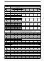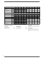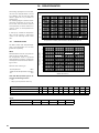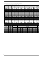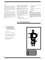
1
English
NRL
R410A
TECHNICAL INSTALLATION MAINTENANCE MANUAL
Chillers and air water heat pumps and motorcondensers with scroll compressors
A
E
HA
HE
HIGH EFFICIENCY
HIGH EFFICIENCY SILENCED VERSION
HIGH EFFICIENCY HEAT PUMP
HIGH EFFICIENCY HEAT PUMP SILENCED VERSION
❄ 57 KW ÷ 83 KW
❊ 59 KW ÷ 86 KW
❄ 90 KW ÷ 163 KW
❊ 103 KW ÷ 171 KW
INRLPY. 0609.4538005_02
Dear Customer,
Thank you for choosing an AERMEC product. This product is the result of many years of experience and in-depth engineering research, and it is built using top quality materials and advanced technologies.
In addition, the CE mark guarantees that our appliances fully comply with the requirements of the European Machinery
Directive in terms of safety. We constantly monitor the quality level of our products, and as a result AERMEC products
are synonymous with Safety, Quality, and Reliability.
Product data may be subject to modifications deemed necessary for improving the product without the obligation to give prior notice.
Thank you again.
AERMEC S.p.A
AERMEC S.p.A. reserves the right at any moment to make any modifications considered necessary to improve our products and is not
obliged to add these modifications to machines that have already been manufactured, delivered or are under construction.
INDEX
1.
1.1.
1.2.
Notes regarding the documentation ..............................................3
Use in compliance with destination .................................................3
Preservation of the documentation ................................................3
17.
Sound data ..............................................................................................29
18.
Calibration of control and safety parameters .........................30
2.
Fundamental safety regulations........................................................3
3.
Product identification .............................................................................3
4.
4.1.
4.2.
4.3.
4.4.
Descrizione dell'unità .............................................................................4
Models available ......................................................................................4
Versions available ....................................................................................4
Silenced motorcondensers (CL) .......................................................4
Configurator...............................................................................................5
19.
19.1.
19.2.
19.3.
19.4.
19.5.
19.6.
19.7.
5.
5.1.
5.2.
5.3.
5.4.
5.5.
5.6.
5.7.
5.8.
5.9.
Description of the components .........................................................6
Nrl 0280-0300-0330-0350............................................................6
Nrl 0500-0550-0600-0650-0700 ..............................................7
Cooling circuits, hydraulic (A - E) .......................................................8
Cooling circuits, hydraulic (HA - HE).................................................9
Cooling circuit......................................................................................... 10
Frame and fans ..................................................................................... 10
Hydraulic components........................................................................ 10
Control and safety components .................................................... 10
Electric components ............................................................................11
Dimensions.............................................................................................. 31
Nrl 0280 - 0300 - 0330 - 0350 .................................................. 31
Minimum technical spaces nrl 0280 - 0300 - 0330 - 0350 ... 31
Anti-vibration mounts position ........................................................ 31
Nrl 0500 - 0550 - 0600 - 0650 - 0700...................................32
Minimum technical spaces 0500 - 0550 - 0600 - 0650 - 0700 ........32
Anti-vibration mounts position ........................................................32
Percentage of wieght distribution on supports ............................
(empty weight) versions (E - HE) .....................................................33
Percentage of weight distribution on supports ...........................
(machine working) versions (E - HE) .............................................34
Percentage of wieght distribution on supports ............................
(empty weight) versions (A - E)........................................................35
Percentage of weight distribution on supports ...........................
(machine working) versions (A - E) ................................................36
Percentage of wieght distribution on supports ............................
(empty weight) versions (HA - HE) ................................................. 37
Percentage of weight distribution on supports ...........................
(machine working) versions (HA - HE) .........................................38
6.
Accessories .............................................................................................11
7.
7.1.
7.2.
7.3.
Technical data ........................................................................................ 13
Technical data for versions (A - E) ................................................. 13
Technical data for versions (HA - HE) .......................................... 15
Technical data for versions (C) ...................................................... 17
8.
8.1.
8.2.
8.3.
Operational limits .................................................................................. 18
Cooling mode functioning ................................................................. 18
Heating mode functioning ................................................................. 18
Motorcondensing functioning ......................................................... 18
9.
9.1.
9.2.
9.3.
9.4.
19.8.
19.9.
19.10.
19.11.
19.12.
20.
Safety warnings and installation regulations............................39
21.
21.1.
21.2.
21.3.
Receiving the product .........................................................................39
Handling ....................................................................................................39
Positioning ...............................................................................................39
Handling example .................................................................................39
22.
22.1.
22.2.
22.3.
22.4.
Hydraulic circuits ..................................................................................40
Hydraulic circuit inside nrl "00" ......................................................40
Hydraulic circuit inside nrl"P1-P2-P3-P4" ..................................40
Hydraulic circuit inside nrl "01-02-03-04-05-06-07-08" .... 41
Hydraulic circuit inside nrl "09-10" ............................................... 41
Corrective coefficients ....................................................................... 19
Cooling capacity and input power ................................................. 19
Heating capacity and input power .................................................20
For ∆t different to the nominal.......................................................20
Deposit factors ......................................................................................20
23.
23.1.
Filter maintenance ...............................................................................42
Procedure to follow to clean the filter: .......................................42
24.
24.1.
Position of hydraulic connections ..................................................43
Position of hydraulic connections motorcondensing version .....44
10.
10.1.
Ethylene glycol solution....................................................................... 21
How to interpret glycol curves ....................................................... 21
11.
11.1.
11.2.
Pressure drops .....................................................................................22
Total pressure drops ..........................................................................22
Total pressure drops ..........................................................................23
25.
25.1.
25.2.
25.3.
25.4.
25.5.
Electrical connections.........................................................................45
Unit electric lines and data...............................................................45
Electrical data ........................................................................................45
"GR3" control board ............................................................................46
Connection to the electric power supply mains ...................... 47
Electric connections ............................................................................48
12.
12.1.
12.2.
12.3.
Storage tank ........................................................................................... 24
Minimum/maximum water content in the system ............. 24
..................................................................................................................... 24
..................................................................................................................... 24
26.
26.1.
26.2.
26.3.
Commissioning ......................................................................................48
Preliminary operations.......................................................................48
Commissioning ......................................................................................49
System loading unloading .................................................................49
13.
Capacity control ....................................................................................25
27.
Maintenance...........................................................................................50
14.
14.1.
Desuperheater ......................................................................................26
Pressure drops .....................................................................................26
15.
15.1.
15.2.
Total recovery......................................................................................... 27
Nrl (T) ......................................................................................................... 27
Pressure drops ..................................................................................... 27
28.
28.1.
28.2.
Disposal ....................................................................................................50
Disconnecting the unit........................................................................50
Dismantling and disposal ..................................................................50
29.
29.1.
Improper use .......................................................................................... 51
Important safety information .......................................................... 51
16.
Dimensionement cooling lines version (C) .................................28
30.
R410A refrigerant gas ....................................................................... 51
For the installation of the appliance, please comply with the safety rules and regulations contained in these instructions
Moving parts hazard
Danger: Disconnect voltage
High temperature hazard
Generic danger
Voltage hazard
i
Useful information and notices
1
AERMEC S.p.A.
37040 Bevilacqua (VR) Italy – Via Roma, 996
Tel. (+39) 0442 633111
Telefax 0442 93730 – (+39) 0442 93566
www .aermec. com - info @ aermec. com
NRL
SERIAL NUMBER
EC DECLARATION OF CONFORMITY
We, the undersigned, hereby declare under our own responsibility that the assembly in
question, defined as follows:
NAME
NRL
TYPE
WATER/WATER HEAT PUMPCHILLER
MODEL
To which this declaration refers, complies with the following harmonised standards:
CEI EN 60335-2-40
Safety standard regarding electrical heat pumps, air conditioners and dehumidifiers
CEI EN 61000-6-1
CEI EN 61000-6-3
Immunity and electromagnetic emissions for residential environments
CEI EN 61000-6-2
CEI EN 61000-6-4
Immunity and electromagnetic emissions for industrial environments
EN378
Refrigerating systems and heat pumps - Safety and environmental requirements
UNI EN 12735
UNI EN 14276
Seamless, round copper tubes for air conditioning and refrigeration
Pressure equipment for cooling systems and heat pumps
Therefore complying with the essential requirements of the following directives:
- LVD Directive: 2006/95/CE
- Electromagnetic compatibility Directive2004/108/CE
- Machinery Directive 98/37/CE
- PED Directive regarding pressurised devices 97/23/CE
The product, in agreement with Directive 97/23/CE, satisfies the Total quality Guarantee procedure (form H) with certificate
n.06/270-QT3664 Rev.3 issued by the notified body n.1131 CEC via Pisacane 46 Legnano (MI) - Italy
Bevilacqua
15/01/2008
Marketing Manager
Signature
2
1.
1.1.
USE IN COMPLIANCE WITH
DESTINATION
AERMEC units are constructed according to the recognised technical standards and safety regulations. These
appliances are designed and built for
heating and hot water production and
also for cooling and must be used in
compatibility with their technical features. In spite of this, dangers to the
user or third parties may arise, as well
as damage to the appliance and other
objects, in the event of improper use
and use that is not in compliance with
that envisioned.
Any use not expressly indicated in this
NOTES REGARDING THE DOCUMENTATION
manual is not permitted. Consequently
AERMEC will not assume any responsibility for damage that may occur
due to failure to comply with these
instructions.
1.2.
PRESERVATION OF THE
DOCUMENTATION
The installation instructions, along with
all the related documentation, must be
given to the user of the system, who assumes the responsibility of keeping the
instructions so that they are always at
hand in case of need.
READ THIS DOCUMENT CAREFULLY, the appliance must be installed by
2.
We remind you that the use of products that employ electrical energy
and water requires that a number
of essential safety rules be followed,
such as:
This appliance is not suitable for use
by persons (including children) with
limited physical, sensory, or mental
capacities or those lacking experience or know-how, unless they are
supervised or instructed regarding
the use of the appliance by a person
who is responsible for their safety.
Children must always be supervised
to ensure they do not play with the
appliance.
qualified and suitably prepared staff in
compliance with the national legislation
effective in the country of destination.
(Ministerial Decree 329/2004).
The appliance must be installed so that
maintenance and/or repairs can be
carried out. The appliance warranty
does not cover the costs for ladders,
scaffolding, or other elevation systems
that may become necessary for carrying out servicing under warranty.
The validity of the warranty shall be
void in the event of failure to comply
with the above-mentioned indications.
FUNDAMENTAL SAFETY REGULATIONS
It is prohibited to carry out any technical or maintenance operation before
the unit has been disconnected from
the electrical mains by switching off
the master switch of the system and
the main power switch on the control
panel.
It is prohibited to modify the safety or
adjustment devices without the manufacturer’s authorisation and precise
instructions
It is prohibited to pull, disconnect, or
twist the electrical cables coming
from the unit even if disconnected
from the electrical mains.
It is prohibited to leave containers
and flammable substances near to
the unit.
It is prohibited to touch the appliance
when you are barefoot and with parts
of the body that are wet or damp.
It is prohibited to open the access
hatches to the internal parts of
the appliance without first having
switched off the system master
switch.
It is prohibited to disperse or abandon the packing materials and they
must be kept out of the reach of children, as they are a potential source
of danger.
PRODUCT IDENTIFICATION
3.
NRL can be identified by means of:
TECHNICAL
PLATE
− Packing label
that reports the identification data of
the product.
AE R M E C SP A - via R oma 44
37040 - B evilacqua (V R ) - I T AL I A
M O D.
vers.
P rod. date
IP
Serial no
C A L DO
HE A T
C HA UD
HE I ZUNG
T S(H P /L P )
P t = kW
F R E DDO
COL D
F R OI D
K UHL UNG
P e = kW
In = A
Is = A
C
M in.
M ax.
R E S.E L /E L .HE AT E R
R E S.E L /E -HE I ZUNG
kW
max
=
P f = kW
P e = kW
In = A
Is = A
P S (H P /L P )
bar
R 407C
Kg
I n R x max = A
I tot max = A
PACKING
LABEL
− Technical plate
positioned on the lateral cross-member
of the electric box.
NOTE:
Tampering, removal, lack of the identification plate or other does not allow
safe identification of the product and will
make any installation or maintenance
operation to be performed difficult.
TECHNICAL
PLATE
AE R M E C SP A - via R oma 44
37040 - B evilacqua (V R ) - I T AL I A
M OD.
vers.
P rod. date
T S(H P /L P )
P t = kW
F R E DDO
COL D
F R OI D
K UHL UNG
P e = kW
In = A
Is = A
C
M in.
M ax.
R E S.E L /E L .HE AT E R
R E S.E L /E -HE I ZUNG
kW
max
=
PACKING
LABEL
IP
Serial no
CA L DO
HE A T
CHA UD
HE I ZUNG
P f = kW
P e = kW
In = A
Is = A
P S (H P /L P )
bar
R 407C
Kg
I n R x max = A
I tot max = A
3
4.
− The appliances in the NRL series
are units used for the production
of cold water for technological
systems. The heat pump models
also allow to produce hot water
for heating. They are made up of
two R410A cooling circuits and a
unique hydraulic circuit, which may
or may not be supplied with storage or pumping unit. The presence
of several scroll compressors allows NRL chillers various partialisations of the cooling capacity.
The electronic adjustment with microprocessor controls and manages all components and functioning
parameters. An internal memory
records the functioning conditions
when an alarm occurs in order to
show it on the display. The units
have an IP 24 protection rating.
4.1.
MODELS AVAILABLE
− “COOLING ONLY” (A - E)
maximum external temperature
accepted 46°C;
− temperature water product 18°C;
− “HEAT PUMP” (HA - HE)
in cooling mode the operational limits reach a maximum external air
temperature of 46°C;
− temperature water product 18°C;
− in heating mode the operational
limits reach a maximum external
air temperature of 42°C;
− temperature water product 55°C;
4
DESCRIZIONE DELL'UNITÀ
−NRLH does not envision the following configurations:
− YH (with water produced lower than 4 °C)
− HC (motorcondencing heat pump)
4.2.
VERSIONS AVAILABLE
4.3.
SILENCED MOTORCONDENSERS (CL)
The NRL-C motorcondensers do not envision
the following versions:
− HC (motorcondencing heat pump)
− TC (motorcondensing with total recovery)
− DC motorcondensing with storage tank.
− HEAT RECUPERATORS:
•
with desuperheater inserted
in series (D).
− ATTENTION:
In heat pump models the desuperheater must be shut-off in heat
pump mode, or the warranty will be
come void.
−
• Total heat recovery (T)
With plate heat exchanger
inserted in parallel with the coils.
− Both of these versions (D - T) have:
− Hot gas by-pass device upstream
from the evaporator.
− Water filter before the recovery
heat exchanger.
Units with Desuperheater (D)
or Total Recovery (T) do not envision
the following versions:
− YD
− YT
− XT (only for temperature under 4°C)
− XD (only for temperature under 4°C)
− version Y: it is the version that allows to produce cooled water below the standard value of +4 °C to a
minimum of -6 °C. Contact the head
office for lower values.
4.4.
CONFIGURATOR
1,2,3
4,5,6
7
8
9
10
11
12
13
14
15, 16
NRL
028
°
°
°
°
°
°
°
°
00
Field
1, 2, 3
Code
NRL
4, 5, 6
Size
028, 030, 033, 035, 050, 055, 060, 065, 070
7
Compressor
°
Standard compressor
8
Thermostatic valve
°
Standard mechanical thermostatic valve
Y
Low water temperature mechanical hermostatic valve (to -6°C)
X
Electronic thermostatic valve also for low water temperature (to -6°C)
9
Model
°
C
H
Cooling Only
Motorcondensing
Heat Pump
10
Heat recovery
°
Without recuperators
D
Desuperheater
T
Total recovery
11
Version
A
E
High efficiency
High efficiency silenced
Coils
°
R
S
V
In aluminium
In copper
Tinned copper
Painted
Fans
°
M
Standard
Larger
12
13
14
Power supply
°
400V-3N-50Hz with magnet circuit breakers
1
230V-3-50Hz with magnet circuit breakers
2
500V-3-50Hz with magnet circuit breakers
15, 16
Storage tank
00
Without hydronic storage tank
01
Low static pressure storage tank and single pump
02
Low static pressure storage tank and reserve pump
03
High static pressure storage tank and single pump
04
High static pressure storage tank and reserve pump
05
Storage tank with holes for int. res. low static pressure and single pump
06
Storage tank with holes for int. res. low static pressure and reserve pump
07
Storage tank with holes for int. res. high static pressure and single pump
08
Storage tank with holes for int. res. high static pressure and reserve pump
09
Double water ring
10
Double water ring with integrated resistance
P1
Without storage tank with low static pressure
P2
Without storage tank with low static pressure pump and reserve pump
P3
Without storage tank with high static pressure
P4
Without storage tank with high static pressure pump and reserve pump
5
5.
5.1.
DESCRIPTION OF THE COMPONENTS
NRL 0280-0300-0330-0350
9
10
8
19
18
15
16
17
7
11
6
12
14
4
3
5
20
2
NOTE:
The drawings shown are only
an example.
1
KEY:
6
13
1
2
Plate heat exchanger
Storage tank
11
12
Compressors
Storage tank draining
3
4
5
6
7
8
9
10
Expansion vessel
Pumps
Loading unit
Safety valve
Vent valve
Coil
Fans
Electric Control Board
13
14
15
16
17
18
19
20
Desuperheater
Mounted filter
Cycle reversing valves
Liquid storage tank
Thermostatic valves
Dehydrator filter
Liquid separator
Electric resistance
5.2.
NRL 0500-0550-0600-0650-0700
9
10
14
8
13
7
18
16
15
17
6
12
4
3
5
20
11
2
NOTE:
The drawings shown are only
an example.
1
KEY:
1
2
Plate heat exchanger
Storage tank
11
12
Compressors
Storage tank draining
3
4
5
6
7
8
9
10
Expansion vessel
Pumps
Loading unit
Safety valve
Vent valve
Coil
Fans
Electric Control Board
13
14
15
16
17
18
19
20
Desuperheater
Mounted filter
Cycle reversing valves
Liquid storage tank
Thermostatic valves
Dehydrator filter
Liquid separator
Electric resistance
7
5.3.
COOLING CIRCUITS,
HYDRAULIC ( A - E )
V
V
VSA
BAT
BAT
RU
VSIC
RU
VSIC
RU
FD
FD
VS
VS
IDL
IDL
PP
EQ
TGP
PP
VT
VT
GR
SA
RU
AP
PP
SF
VE
caricamento
RE
SD
AP
EQ
TGP
RU
PP
P
P
CP
RS
CP
VNR VNR
SIW
BVT
BP
FM
BVT
PP
SC
PP
BP
FL
SUW
QE
QE
FM
VE
--VaS
VSA
TGP
CP
FL
SA
SF
8
Electric Control Board
Water filter
Expansion vessel
Electric cable
Ball valve
Water safety valve
Pressing line gas circuit breaker
Compressor
Flow switch
Water tank
Venting
V
BAT
RU
FD
VT
SC
PP
TAP
RU
BP
RS
Fan
Coil
Cock
Dehydrator filter
Thermostatic valve
Heat exchanger
Pressure point
High pressure transducer
Cock
Low pressure switch
Drain cock
SD
RE
VNR
P
GR
RU
SD
RE
VNR
P
GR
Anti-freeze probe
300W electric resistance
Non-return valve
Pump
Filling unit
Cock
Anti-freeze probe
Electric resistance
Non-return valve
Pump
Filling unit
VS
IDL
EQ
BVT
SIW
SUW
AP
Solenoid valve
Liquid indicator
Equaliser
Temperature control valve bulb
Inlet water temperature probe
Outlet water temperature probe
High pressure pressure switch
5.4.
COOLING CIRCUITS,
HYDRAULIC ( HA - HE )
VSA
V
V
RCS
BAT
BAT
PP
VIC
PP
TAP
AP
VU EQ
VU
SEP
TGP
PP
SD
BVT
VU
FD
FD
VS
VS
IL
IL
VT
VSIC
CP
SA
AL
EQ VU
BVT
VS
VS
VT
BP
C
VU
RS
RU
AP
P
VSIC
TBP
PP
VU
VIC
PP
TAP
TGP
PP
TBP
PP
VU
VIC
SEP
BP
C
VU
caricamento
GR
RE
PP
AL
VIC
SF
VE
RCS
VNR
P
VNR
CP
SIW
FM
SC
FL
SUW
QE
QE
FM
ELECTRIC CONTROL BOARD
Water filter
VE
--VU
AL
CP
VSA
TGP
SA
SF
RCS
Expansion vessel
Electric cable
One-way valve
Liquid storage tank
Compressor
Water safety valve
Pressing line gas circuit breaker
Water tank
Venting
Load/drain cock
V
BAT
RU
FD
VT
SC
PP
TAP
VSIC
BP
RS
SEP
Fan
Coil
Cock
Dehydrator filter
Thermostatic valve
Heat exchanger
Pressure point
High pressure transducer
Safety valve
Low pressure switch
Drain cock
Liquid separator
SD
RE
VNR
P
GR
RU
SD
RE
VNR
P
GR
VIC
Anti-freeze probe
300W electric resistance
Non-return valve
Pump
Filling unit
Cock
Anti-freeze probe
Electric resistance
Non-return valve
Pump
Filling unit
Cycle reversing valve
VS
IDL
EQ
BVT
SIW
SUW
AP
TBP
FL
Solenoid valve
Liquid indicator
Equaliser
Temperature control valve bulb
Inlet water temperature probe
Outlet water temperature probe
High pressure pressure switch
Low pressure transducer
Flow switch
9
5.5.
COOLING CIRCUIT
Compressors
Highly efficient hermetic scroll compressors on anti-vibration mounts, activated by
a 2-pole electric motor with internal circuit
breaker protection, supplied as per standard with sump resistance. The resistance
is powered automatically when the unit
stops as long as the unit is live.
Air-side heat exchanger
High efficiency realised with copper pipes
and aluminium louvers blocked by mechanical expansion of the pipes.
Water-side heat exchanger
Plate type (aisi 316), insulated externally
with closed cell material to reduce heat
loss. Equipped as per standard with the
anti-freeze electric resistance.
Liquid separator
(for heat pump only)
Positioned on compressor intake for protection against any return of refrigerant
fluid, flooded start-up and functioning in the
presence of liquids.
Liquid storage tank
(for heat pumps and total recovery only)
Compensates the difference in volume
between louvers coil and plate exchanger,
withholding excess liquid.
Dehydrator filter
Mechanical dehydrator filter realised in
ceramics and hygroscopic material, able
to withhold impurities and any traces of
humidity present in the cooling circuit.
Liquid indicator
Used to check the refrigerant gas load and
any presence of humidity in the cooling circuit.
Thermostatic valve
The mechanical valve, with external equaliser positioned at evaporator outlet, modulates the flow of gas to the evaporator, depending on the heat load, in order to ensure
a correct level of heating of the intake gas.
Liquid and pressing line cocks
(cooling versions only)
Allows interruption of the refrigerant in the
case of extraordinary maintenance.
Solenoid valve
The valve closes when the compressor
switches off, blocking the flow of refrigerant
gas to the evaporator.
By-pass solenoid valve (heat pump only)
By-passes the thermostatic valve during
the de-frosting cycle.
Cycle reversing valve (heat pump only)
It reverses the flow of refrigerant on vari10
ation of summer/winter mode and during
de-frosting cycles.
One-way valve
Allows one-way flow of the refrigerant.
Filling unit
(versions with storage tank)
It is equipped with a manometer for the display of system pressure.
Desuperheater (on request only)
Plate type (AISI 316), insulated externally
with closed cell material to reduce heat loss.
Expansion vessel
(versions with storage tank)
with nitrogen pre-load membrane.
Total recovery (on request only)
Plate type (AISI 316), insulated externally with
closed cell material to reduce heat loss.
Hydraulic circuit safety valve
(only in versions with storage tank or with pump)
Calibrated at 6 Bar and with piped discharge, which intervenes by discharging
overpressure if abnormal work pressures
occur.
5.6.
FRAME AND FANS
Ventilation Unit
Helical type, balanced statically and dynamically. The electric fans are protected
electrically by magnet circuit breakers
and mechanically by metal anti-intrusion
grids, according to the IEC EN 60335-2-40
Standard.
Larger fans (M)
Support frame
Made in hot galvanised sheet steel with suitable thickness and painted with polyester
powders able to resist atmospheric agents
through time
5.7.
HYDRAULIC COMPONENTS
Circulation pump
Depending on the features of the pump
selected, it offers a static pressure that is
useful for beating system pressure drops.
The possibility of a reserve pump is also envisioned. The reserve pump is managed by
the circuit board.
Flow switch (installed as per standard)
It checks that there is circulation of water. If
this is not the case, it blocks the unit.
Water filter (installed as per standard)
This allows to block and eliminate any impurities present in the hydraulic circuits. It
contains a filtering mesh with holes that do
not exceed one millimetre. It is indispensable in order to prevent serious damage to
the plate exchanger.
Storage tank
In sheet steel with capacity of 300 litres. In
order to reduce heat loss and eliminate the
condensate formation phenomenon, it is insulated using polyurethane material with a
suitable thickness.
As per standard it has a 300W anti-freeze
electric resistance (to -20°C external temperature- tank water temperature 5°C)
controlled by the board using an anti-freeze
probe inserted into the tank.
Vent valve (all versions)
Automatic, mounted on the upper part of
the hydraulic plant; it discharges any air
pockets present in the same.
5.8.
CONTROL AND SAFETY
COMPONENTS
Low pressure pressure switch (LP)
- Cooling only (E)
With fixed calibration, placed on low pressure side of cooling circuit, it inhibits functioning of compressor if abnormal work
pressure occurs.
High pressure pressure switch (AP)
- Cooling only (E)
- Heat pump (HE)
With fixed calibration, placed on high pressure side of cooling circuit, it inhibits functioning of compressor if abnormal work
pressure occurs.
Low pressure transducers (TP2)
- Cooling only (E) "accessory"
- Heat pump (HE) "as per standard"
Placed on high pressure side of cooling circuit, it signals the work pressure to control
board, generating a pre-warning if abnormal pressure occurs.
High pressure transducers (TP3)
- Cooling only (E) "accessory"
- Heat pump (HE ) "as per standard"
Placed on high pressure side of cooling circuit, it signals the work pressure to control
board, generating a pre-warning if abnormal pressure occurs.
Anti-freeze electric resistance
(installed as per standard)
Its functioning is controlled by the antifreeze probe positioned in the plate evaporator. Activation takes place when the
temperature of the water is +3°C, while it
is disconnected with water temperature of
+5°C. The dedicated software, housed in
the adjustment board, manages the electric resistance.
Cooling circuit safety valve
Intervenes by discharging the overpressure
in the case of abnormal pressures.
- Calibrated at 45 bar on the HP branch
- Calibrated at 30 bar on the LP branch
(heat pump only)
5.9.
ELECTRIC COMPONENTS
Electric Control Board
Contains the power section and the management of controls and safety devices.
It is in compliance with the following
Standards
IEC EN 61000-6-1
IEC EN 61000-6-3 (electromagnetic immunity and emission for residential environments).
IEC EN 61000-6-2
IEC EN 61000-6-4 (electromagnetic immunity and emission for industrial environments).
With the Directives regarding electromagnetic compatibility EMC 89/336/CEE and
92/31/CEE and LVD 2006/95/CE.
Door-lock isolating switch
The electric control board can be accessed
by removing the voltage. Act on the opening
lever of the control board itself. This lever can
be locked using one or more padlocks during
maintenance interventions to prevent the
machine being powered up accidentally.
Control board
Allows the complete control of the appliance. For a more in-depth description please
refer to the user manual.
Remote control panel
Allows to control the chiller at a distance.
Compressors magnet circuit breaker protection;
Fans magnet circuit breaker protection;
Auxiliary magnet circuit breaker protection;
Exhaust gas temperature control thermostat thermostat.
ELECTRONIC ADJUSTMENT
Microprocessor board
Made up from management and control board
and display board.
• Functions performed:
evaporator inlet water temperature
adjustment with thermostating up
to 4 steps and proportional control
- integral on fan speed (with DCPX
accessory).
delayed start-up of compressors.
compressors rotation sequence.
compressors functioning hours count.
start/stop.
reset.
alarms permanent memory.
autostart after voltage drop.
multi-language messages.
functioning with local or remote control.
-
• machine status display:
compressors ON/OFF;
alarms summary.
6.
0280
A
E
HA
HE
AER485
•
•
0300
0330
-
• alarms management:
high pressure;
flow switch;
low pressure;
anti-freeze;
compressors overload;
fans overload;
pumps overload.
-
• display of the following parameters:
inlet water temperature;
Storage tank temperature.
outlet water temperature
Outlet water temperature;
delta T;
high pressure; low pressure;
re-start stand-by time.
alarms display.
• set settings:
a) without password:
set cooling;
total differential;
b) with password:
set anti-freeze;
low pressure exclusion time;
display language;
access code.
For further information, please refer to
user manual.
ACCESSORIES
0350
0500
0550
0600
VT (01-02-03-04-05Rubber or spring anti-vibration mounts. Select the model using the compatibility table.
06-07-08)
A
13
13
13
E
13
10
10
10
HA
13
13
13
HE
13
13
22
10
22
3
3
Protects the external coil from blows and prevents access to the area below where the compressors and cooling circuit are
housed. Every kit includes two grids.
4
4
4
2(x2)
2(x2)
2(x2)
2(x2)
2(x3)
4
4
4
•
•
Board to couple onto the unit circuit board. Allows to program two time periods per day (two switch-on/off cycles) and to have differentiated programming for every day of the week.
•
•
•
•
•
•
•
•
•
•
•
•
•
•
•
•
•
•
•
•
•
•
•
•
•
•
GP
PGS
A
E
HA
HE
0700
This accessory allows connection of the unit to BMS supervising systems with RS485 electric standard and MODBUS protocol.
•
•
•
•
•
•
•
•
•
•
•
•
•
•
•
•
•
•
•
•
•
•
•
•
•
•
VT ( 00-P1-P2-P3-P4 ) Rubber or spring anti-vibration mounts. Select the model using the compatibility table.
A
17
17
17
E
17
13
13
13
HA
17
17
17
HE
17
A
E
HA
HE
0650
11
0280
as per standard as per standard as per standard as per standard
TP3
(x2)
-
56
58
•
•
MULTICHILLER
•
•
TRX1
•
•
•
•
PRM 1
12
It allows to view the value of the compressor flow pressure on the microprocessor board display (one per circuit). Placed on the high pressure side of the cooling circuit, it inhibits functioning of the compressor if abnormal work pressures occur.
(x2)
(x2)
(x2)
as per standard as per standard as per standard as per standard as per standard
-
701
This accessory allows correct functioning with external temperatures lower than 10 °C and to – 10 °C.
It is made up from an adjustment circuit board that varies the number of fan revs. on the basis of condensation pressure read by
the high pressure transducer, in order to keep it high enough for correct unit functioning.
It also allows correct functioning in heating mode with external temperatures exceeding 30°C and up to 42°C.
64
64
64
64
64
as per standard as per standard as per standard as per standard as per standard
56
57
57
64
64
64
64
65
as per standard as per standard as per standard as per standard as per standard
58
59
59
DCPX only for configurations with larger fans (M).
61
63
DUALCHILLER
A
E
HA
HE
as per standard as per standard as per standard as per standard as per standard
It allows the reduction of peak power necessary for the machine during start-up phase (accessory applicable only in the factory).
301
331
351
501
551
601
651
301
331
351
DCPX
A
E
HA
HE
0700
281
281
DCPX
A
E
HA
HE
0650
50
50
DRE
A
E
HA
HE
0600
Current rephaser. Connected in parallel to the motor, it allows a reduction of the absorbed current. (It can only be installed
in the machine construction phase and so must be requested on ordering).
50
50
51
52
53
53
53
52
50
50
51
A
E
HA
HE
A
E
HA
HE
0550
as per standard as per standard as per standard as per standard
RIF
A
E
HA
HE
0500
(x2)
-
TP2
A
E
HA
HE
0350
It allows to view the value of the compressor intake pressure on the microprocessor board display (one per circuit). Placed on the low
pressure side of the cooling circuit, it inhibits functioning of the compressor if abnormal work pressures occur.
(x2)
(x2)
(x2)
(x2)
(x2)
(x2)
(x2)
(x2)
-
A
E
HA
HE
A
E
HA
HE
0330
•
•
AERWEB30
A
E
HA
HE
0300
The AERWEB device allows theremote control of a chiller from a common PCby means of a serial connection. By using
addi-tional modules the device allows control of thechiller by telephone network, using the AER-MODEM; accessory or
GSM network, usingthe AERMODEMGSM. The AERWEB can pilotup to 9 chillers, each of which must be equip-ped with
the AER485 or AER485P2 accessory.
•
•
•
•
•
•
•
•
•
•
•
•
•
•
•
•
•
•
•
•
•
•
•
•
•
•
•
•
•
•
61
63
61
63
61
63
64
64
64
64
65
as per standard as per standard as per standard as per standard as per standard
DCPX - not necessary, fans already control their speed
Simplified control system for control, switch-on/off of two chillers, with Amec GR3 control, in the same plant as if they were the same unit.
•
•
•
•
•
•
•
•
•
•
•
•
•
•
•
•
•
•
•
•
•
•
•
•
•
•
Control system for control, switch-on/off of the single chillers in a plant in where multiple units are installed in parallel, always ensuring
constant flow to the evaporators.
•
•
•
•
•
•
•
•
•
•
•
•
•
•
•
•
•
•
•
•
•
•
•
•
•
•
The water accumulators with holes and supplementary electric heaters leave the factory with plastic protection caps. Before loading
the system, if the installation of an electric heater is not envisaged it is compulsory to replace the plastic caps with the special TRX1.
•
•
•
•
•
•
•
•
•
•
•
•
•
•
•
•
•
•
•
•
•
•
•
•
•
•
•
•
•
•
•
•
FACTORY FITTED ACCESSORY. It is a manual pressure switch electrically wired in series with the existing automatic high
pressure switch on the compressor discharge pipe.
•
•
•
•
•
•
•
•
•
•
•
•
•
•
•
•
•
•
•
•
•
•
•
•
•
•
•
•
•
•
•
•
7.
7.1.
TECHNICAL DATA
TECHNICAL DATA FOR VERSIONS ( A - E )
COOLING
Cooling capacity
kW
Total input power
kW
Water flow rate
l/h
Total pressure drops
kPa
A
E
A
E
A
E
A
E
0280
57
16,8
9800
43
0300
65
19,4
11180
39
0330
74
21,8
12730
35
0350
83
25,1
14280
44
0500
98
90
30,2
33,1
16860
15480
44
37
0550
104
95
34,2
36,7
17890
16340
49
41
0600
129
117
40,1
44,3
22190
20120
54
44
0650
143
129
44,6
51,6
24600
22190
60
49
0700
163
150
52,3
56,6
28040
25800
68
58
A
E
A
E
3,39
3,94
3,35
3,89
3,39
3,94
3,31
3,84
3,25
2,72
3,83
3,78
3,04
2,59
3,59
3,55
3,22
2,64
4,28
4,15
3,21
2,50
4,26
4,13
3,12
2,65
4,15
4,02
ENERGETIC INDEX
EER
W/W
ESEER
W/W
ELECTRICAL DATA
Power supply
A
Absorbed current
A
Maximum current
A
Peak current
A
A
E
A
E
A
E
A
E
30
46
155
34
53
184
37
58
190
45
63
200
A
E
2/2
2/2
2/2
2/2
A
E
A
E
A
E
A
E
A
E
6
22000
0,9
3,9
50
6
22000
0,9
3,9
50
8
27000
1,2
5,2
50
8
27000
1,2
5,2
50
400V-3N-50Hz
55
60
60
64
71
78
77
89
90
97
76
81
100
112
122
214
220
232
243
261
3/2
3/2
4/2
4/2
4/2
2
2
2
2
3
34100
21100
34100
22200
32600
21800
32600
22800
50000
32500
2,5
2,5
2,5
2,5
3,75
5,6
5,6
5,6
5,6
8,4
50
50
50
50
50
COMPRESSORS (SCROLL)
Number/circuit
n°/n°
FANS (AXIAL)
Quantity
n°
Air flow rate
m³/h
Input power
kW
Absorbed current
A
Useful static pressures [1] "M"
Pa
EVAPORATORS (PLATE)
Quantity
n°
A
E
1
1
1
1
1
1
1
1
1
HYDRAULIC CONNECTIONS
Hydraulic circuit
connections* (IN/OUT)
Ø
A
E
2"1/2
2"1/2
2"1/2
2"1/2
2"1/2
2"1/2
2"1/2
2"1/2
2"1/2
A
E
A
E
300
300
300
300
300
300
300
300
500
500
500
500
500
300
300
300
300
300
LOW STATIC PRESSURE CIRCULATION PUMP
A
Input power
KW
E
1,1
A
Absorbed current
A
E
2,7
A
Useful static pressures
KPa
E
113
1,1
2,7
114
1,1
2,7
114
1,1
2,7
102
1,5
1,5
1,5
1,5
1,85
3,6
3,6
3,6
3,6
5,0
127
140
117
132
94
117
76
104
78
106
HYDRAULIC CIRCUIT
Storage tank capacity
Storage tank anti-freeze
resistance
l
W
* The water connections are all ‘Victaulic’ type
[1] The static pressures available refer to the nominal air flow rate.
13
0280
HIGH STATIC PRESSURE CIRCULATION PUMP
A
Input power
KW
E
1,5
A
A
Absorbed current
E
3,6
A
KPa
Useful static pressures
E
152
0300
0330
0350
1,5
3,6
153
1,5
3,6
153
1,5
3,6
140
0500
0550
0600
0650
0700
1,85
1,85
3,0
3,0
3,0
5,0
5,0
5,7
5,7
5,7
166
179
156
171
188
215
172
201
140
170
82
74
50
42
82
74
50
42
82
74
50
42
83
75
51
43
85
77
53
45
1875
1875
1875
1875
1875
1100
1100
1100
1100
1100
2950
2950
2950
2950
3950
1099
1103
1204
1212
1390
SOUND DATA
Sound power (1)
dBA
Sound Pressure (2)
dBA
A
E
A
E
74
42
74
42
75
43
76
44
A
E
A
E
A
E
A
E
1606
1100
2450
686
1606
1100
2950
751
1606
1100
2950
761
1606
1100
2950
767
DIMENSIONS
Height
mm
Width
mm
Depth
mm
Empty weight
Kg
REFERENCE NOMINAL CONDITIONS
IN COOLING MODE
- Inlet water temperature
- Outlet water temperature
- External air temperature
- ∆t
14
12 °C
7 °C
35 °C
5°C
(1) SOUND POWER
Aermec determines sound power values in agreement with
the 9614-2 Standard, in compliance with that requested by
Eurovent certification.
(2) SOUND PRESSURE
Sound pressure measured in free field conditions with
reflective surface (directivity factor Q=2) at 10mt distance
from external surface of unit, in compliance with ISO 3744
regulations.
7.2.
TECHNICAL DATA FOR VERSIONS ( HA - HE )
COOLING
Cooling capacity
kW
Total input power
kW
Water flow rate
l/h
Total pressure drops
kPa
HA
HE
HA
HE
HA
HE
HA
HE
0280
57
16,8
9800
43
0300
65
19,4
11180
39
0330
74
21,8
12730
35
0350
83
25,1
14280
42
HA
HE
HA
HE
HA
HE
HA
HE
53
17,9
9120
20
62
20,0
10660
27
69
23,0
11870
23
77
26,6
13240
29
HA
HE
HA
HE
HA
HE
2,96
3,94
3,41
3,10
3,89
3,40
3,00
3,94
3,88
2,89
3,84
3,33
0500
94
90
30,2
33,1
16170
15480
33
30
0550
100
95
34,2
36,4
17200
16340
36
32
0600
122
114
40,1
45,0
20980
19610
36
31
0650
138
128
44,6
52,7
23740
22020
43
37
0700
150
143
52,3
57,8
25800
24610
49
45
103
110
135
152
171
31,2
33,8
40,1
44,9
52,1
17720
18920
23220
26140
29410
40
44
44
52
64
3,09
2,72
3,83
3,78
2,98
2,61
3,59
3,55
2,98
2,53
4,28
4,15
2,89
2,43
4,26
4,13
2,92
2,48
4,15
4,02
3,30
3,25
3,37
3,39
3,28
HEATING
Heating capacity
kW
Total input power
kW
Water flow rate
l/h
Total pressure drops
kPa
ENERGETIC INDEX
EER
W/W
ESEER
W/W
COP
W/W
ELECTRICAL DATA
Power supply
A
Absorbed current
A
Maximum current
A
Peak current
A
HA
HE
HA
HE
HA
HE
HA
HE
35
46
155
39
53
184
43
58
190
49
63
200
HA
HE
2/2
2/2
2/2
2/2
HA
HE
HA
HE
HA
HE
HA
HE
HA
HE
6
20000
0,9
3,9
50
8
26000
1,2
5,2
50
8
26000
1,2
5,2
50
8
26000
1,2
5,2
50
400V-3N-50Hz
55
60
59
64
72
79
82
91
88
99
76
81
100
112
122
214
220
232
243
261
3/2
3/2
4/2
4/2
4/2
2
2
2
2
3
37000
20200
37000
21100
36500
21400
36500
22400
58000
31900
2,5
2,5
2,5
2,5
3,75
5,6
5,6
5,6
5,6
8,4
70*
70*
70*
70*
70*
COMPRESSORS (SCROLL)
Number/circuit
n°/n°
FANS (AXIAL)
Quantity
n°
Air flow rate
m³/h
Input power
kW
Absorbed current
A
Useful static pressures [1] "M"
Pa
EVAPORATORS (PLATE)
Quantity
n°
HA
HE
1
1
1
1
1
1
1
1
1
HYDRAULIC CONNECTIONS
Hydraulic circuit
connections* (IN/OUT)
Ø
HA
HE
2"1/2
2"1/2
2"1/2
2"1/2
2"1/2
2"1/2
2"1/2
2"1/2
2"1/2
HA
HE
HA
HE
300
300
300
300
300
300
300
300
500
500
500
500
500
300
300
300
300
300
HYDRAULIC CIRCUIT
Storage tank capacity
Storage tank anti-freeze
resistance
l
W
LOW STATIC PRESSURE CIRCULATION PUMP
HA
Input power
KW
1,5
1,5
1,5
1,5
1,85
HE
1,5
1,5
1,5
1,5
HA
Absorbed current
A
3,6
3,6
3,6
3,6
5
HE
3,6
3,6
3,6
3,6
HA
141
133
124
95
113
Useful static pressures
KPa
HE
135
126
128
120
147
140
135
114
125
* The water connections are all ‘Victaulic’ type
[1] The static pressures available refer to the nominal air flow rate.
[*] As for the NRL0500-0700 the fans for the “M” version are inverter-type. The DCPX accessory is not meant fort his version as the fans are already equipped
with the fan speed regulation.
15
0280
HIGH STATIC PRESSURE CIRCULATION PUMP
HA
Input power
KW
HE
1,5
HA
Absorbed current
A
HE
3,6
HA
KPa
Useful static pressures
HE
175
0300
0330
0350
1,5
3,6
165
1,5
3,6
166
1,5
3,6
157
0500
0550
0600
0650
0700
1,85
1,85
3
3
3
5
5
5,7
5,7
5,7
181
186
173
180
211
223
181
200
177
192
82
74
50
42
82
74
50
42
82
74
50
42
83
75
51
43
85
77
53
45
1875
1875
1875
1875
1875
1100
1100
1100
1100
1100
2950
2950
2950
2950
3950
1099
1103
1204
1212
1390
SOUND DATA
Sound power (1)
dBA
Sound Pressure (2)
dBA
HA
HE
HA
HE
74
42
75
43
75
43
76
44
HA
HE
HA
HE
HA
HE
HA
HE
1606
1100
2450
730
1606
1100
2950
795
1606
1100
2950
805
1606
1100
2950
811
DIMENSIONS
Height
mm
Width
mm
Depth
mm
Empty weight
Kg
REFERENCE NOMINAL CONDITIONS
IN COOLING MODE
- Inlet water temperature
- Outlet water temperature
- External air temperature
- ∆t
16
IN HEATING MODE
12 °C
7 °C
35 °C
5°C
- Inlet water temperature
- Outlet water temperature
- External air temperature
- ∆t
40 °C
45 °C
7/6 °C
5°C
(1) SOUND POWER
Aermec determines sound power values in agreement with
the 9614-2 Standard, in compliance with that requested by
Eurovent certification.
((2) SOUND PRESSURE
Sound pressure measured in free field conditions with
reflective surface (directivity factor Q=2) at 10mt distance
from external surface of unit, in compliance with ISO 3744
regulations.
7.3.
TECHNICAL DATA FOR VERSIONS (C)
280
300
330
350
500
550
600
650
700
A
E
A
E
59
17,0
67
19,6
76
22,0
85
25,3
101
93
30,5
33,4
107
98
34,5
37,0
133
121
40,5
44,7
147
133
45,0
52,1
168
155
52,8
57,1
A
E
3,46
3,42
3,47
3,38
3,31
2,78
3,10
2,64
3,28
2,70
3,27
2,55
3,18
2,71
COOLING
Cooling capacity
KW
Total input power
KW
ENERGETIC INDEX
EER
W
DATI ELETTRICI RAFFREDDAMENTO
Power supply
A
Cooling absorbed current
A
Maximum current (FLA)
A
Peak current (LRA)
A
A
E
A
E
A
E
A
E
35,3
46
155
39,4
53
184
43,4
58
190
49,4
63
200
A
E
6
6
8
A
E
A
E
74
42
74
42
A
E
A
E
A
E
A
E
1606
1100
2450
662
1606
1100
2950
724
400V-3N-50Hz
55,5
60,5
71,5
77,7
90,9
70,5
64,9
78,9
89,9
97,9
76
81
100
112
122
214
220
232
243
261
8
2
2
2
2
3
75
43
76
44
82
74
50
42
82
74
50
42
82
74
50
42
83
75
51
43
85
77
53
45
1606
1100
2950
730
1606
1100
2950
736
1875
1875
1875
1875
1875
1100
1100
1100
1100
1100
2950
2950
2950
2950
3950
918
922
1098
1105
1264
FANS (AXIAL)
Quantity
n°
SOUND DATA
Sound power (1)
dBA
Sound Pressure (2)
dBA
DIMENSIONS
Height
mm
Width
mm
Depth
mm
Empty weight
Kg
REFERENCE NOMINAL CONDITIONS
IN COOLING MODE
- External air temperature
- Evaporation temperature
(1) SOUND POWER
Aermec determines sound power values in agreement with the 9614-2 Standard, in
compliance with that requested by Eurovent certification.
35 °C
5°C
(2) SOUND PRESSURE
Sound pressure measured in free field conditions with reflective surface (directivity
factor Q=2) at 10mt distance from external surface of unit, in compliance with ISO 3744
regulations.
17
8.
OPERATIONAL LIMITS
8.1. COOLING MODE FUNCTIONING
KEY:
Functioning with glycol
Functioning with glycol with
DCPX accessory
Standard functioning
Standard functioning with
DCPX accessory
40
35
External air temperature d. b. °C
NOTE:
In the cooling mode the unit can be
started up with ambient air at 46°C
and inlet water at 35°C
In the heating mode the unit can be
started up with ambient air at -15°C
and inlet water at 20°C
The unit can operate at these conditions only for the time which is necessary to achieve the right temperature
in the plant. To reduce this time it is
recommended to install a 3-way valve
that allows to bypass the water flow in
the plant until the achievement of the
conditions that allow the unit to work
within the proper operating limits
46
45
30
25
20
15
10
5
0
-5
-10
-15
-5
0
5
10
15
Temperature of the water produced °C
18
8.2. HEATING MODE FUNCTIONING
Temperature of the water produced °C
The units, in standard configuration,
are not suitable for installation in salty
environments. Maximum and minimum
limits for water flow rates at the exchanger are indicated by the curves in
the pressure drop diagrams.
For functioning limits, please refer to
the below diagrams, values for ∆t =
5°C.
External air temperature d. b. °C
NOTE: As for the versions with buffer tank (09-10) the operating limits in cooling
and heating mode are 3°C lower
8.3. MOTORCONDENSING FUNCTIONING
46
45
42
40
External air temperature d. b. °C
35
30
25
20
15
10
5
0
-5
-10
-15
-6
-4
-2
0
2
4
6
Evaporation temperature °C
18
8
10
12
14 15
9.
9.1.
COOLING CAPACITY AND
INPUT POWER
CORRECTIVE COEFFICIENTS
COOLING CAPACITY CORRECTIVE COEFFICIENTS
20°C
1,6
25°C
1,5
30°C
1,4
− "STANDARD VERSIONS"
1,2
− "HEAT PUMP VERSIONS IN COOLING MODE"
1,1
Cf
The cooling capacity efficiency and electrical input power in conditions differing
from normal conditions are obtained
by multiplying the nominal values (Pf,
Pa) by the respective corrective coefficients (Cf, Ca).
The following diagrams show how to
obtain corrective coefficients to use
for units in their various versions in cooling mode; external air temperature,
to which reference is made, is shown in
correspondence to each curve.
35°C
1,3
40°C
1
45°C
0,9
46°C
0,8
0,7
0,6
0,5
0,4
-6
-4
-2
0
2
4
6
8
10
12
1,3
46°C
45°C
FOR ∆t DIFFERENT TO 5°C
At the evaporator use Tab. 9.3.1.
to obtain the correction factors of the
cooling capacity and input power. In order to consider exchanger dirtying, use
the relative dirtying factors Tab. 9.4.1.
Ca a freddo
40°C
35°C
30°C
1,1
25°C
1
20°C
0,9
0,8
0,7
0,6
-6
-4
-2
0
2
4
6
8
10
12
14
16
18
Water produced (°C)
VERSION C COOLING CAPACITY CORRECTIVE COEFFICIENTS
1,6
20°C
1,5
25°C
30°C
1,4
35°C
1,3
40°C
1,2
1,1
1
Cf
Corrective co-efficient of the
input power.
18
1,4
0,9
45°C
0,8
46°C
0,7
0,6
0,5
0,4
-6
-4
-2
0
2
4
6
8
10
12
14
15
Evaporation temperature [°C]
VERSION C INPUT POWER CORRECTIVE COEFFICIENTS
1,4
1,3
46°C
1,2
45°C
40°C
1,1
Ca
Ca:
Corrective co-efficient of the
cooling capacity.
16
INPUT POWER IN COOLING MODE CORRECTIVE COEFFICIENTS
1,2
KEY:
Cf:
14
Water produced (°C)
35°C
30°C
1,0
25°C
0,9
20°C
0,8
0,7
0,6
-6
-4
-2
0
2
4
6
8
10
12
14
15
Evaporation temperature [°C]
19
9.2.
HEATING CAPACITY AND
INPUT POWER
HEATING CAPACITY CORRECTIVE CO-EFFICIENTS
The heating capacity efficiency and electrical input power in conditions differing
from normal conditions are obtained by
multiplying the nominal values (Pt, Pa)
by the respective coefficient correctives (Ct, Ca).
The following diagram shows how to
obtain corrective coefficients; the produced hot water temperature, to which
reference is made, is shown in correspondence to each curve, assuming a
water temperature difference equal to
5°C between the condenser inlet and
outlet.
The yields are intended net of de-frosting cycles.
Ct
− "HEAT PUMP VERSIONS"
External air temperature (°C)
INPUT POWER IN HEATING MODE CORRECTIVE CO-EFFICIENTS
Ca:
Corrective co-efficient of the
input power.
Ct:
Corrective co-efficient of the
heating capacity.
Ca a caldo
KEY:
External air temperature (°C)
9.3.
FOR ∆T DIFFERENT TO THE
NOMINAL
For ∆t different from 5°C at the evaporator use Tab. 9.3.1. to obtain the correction factors of the cooling capacity
and input power. In order to consider
exchanger dirtying, use the relative dirtying factors Tab.9.4.1.
9.4.
DEPOSIT FACTORS
The performances shown by the table
refer to clean tubes with deposit factor=1.
For different deposit factor values, multiply the data in the performance tables
by the co-efficients given.
20
9.3.1. Corrective factors at ∆t different from the Chiller nominal
Cooling capacity correction factors
Input power correction factors
3
0,99
0,99
5
1
1
8
1,02
1,01
10
1,03
1,02
9.4.1. Deposit factors
Cooling capacity correction factors
Input power correction factors
[K*m2]/[W] 0,00005
1
1
0,0001
0,98
0,98
0,0002
094
0,95
10. ETHYLENE GLYCOL SOLUTION
10.1.
HOW TO INTERPRET GLYCOL
CURVES
The curves shown in the diagram summarise a significant number of data,
each of which is represented by a specific curve. In order to use these curves
correctly it is first necessary to make
some initial reflections:
− If you require to calculate glycol
percentage based on the temperature of the external air, enter from
the left axis of the graph and once
the curve is intercepted draw a vertical line, which in turn will intercept
all the remaining curves; the points
obtained from the upper curves
represent the co-efficients for cooling capacity and input power for
flow rates and pressure drops (remember that these co-efficients still
need to be multiplied by the nominal
value of the size in question); whilst
the lower axis recommends the
glycol percentage value necessary
for producing water at the desired
temperature.
− If you require to calculate glycol
percentage based on the temperature of water produced, enter from
the right axis of the graph and once
the curve is intercepted draw a vertical line, which in turn will intercept
all the remaining curves; the points
2.20
FcGDpF (a)
2.10
FcGDpF (b)
2.00
FcGDpF (c)
1.90
FcGDpF (d)
1.80
1.70
1.60
FcGDpF (e)
1.50
1.390
1.40
1.30
1.310
1.20
1.180
1.10
1.00
1.090
FcGQF
1.280
FcGQ (PdC)
1.110
FcGPf (PdC)
1.000
0.99
0.990
0.98
FcGPa
0.975
0.97
0.96
0.95
FcGPf
5
0
5
-5
-10
-6
0
-3
-15
-20
-25
-30
-35
-40
0
5
10
15
20
25
30
35
40
45
50
55
Glycol %
KEY:
FcGPf
FcGPa
FcGDpF (a)
FcGDpF (b)
FcGDpF (c)
FcGDpF (d)
FcGDpF (e)
FcGQF
FcGQC
Temperature of water produced
0.94
External air temperature
− The correction factors of cooling
capacity and input power take into
account the presence of glycol and
diverse evaporation temperature.
− The pressure drop correction factor considers the different flow rate
resulting from the application of the
water flow rate correction factor.
− Correction factor of water flow rate
is calculated to keep the same ∆t
that would be present with the absence of glycol.
NOTE
An example is given on the next page to
help graph reading.
Using the diagram below it is possible
to determine the percentage of glycol
required; this percentage can be calculated by taking one of the following factors into consideration:
Depending on which fluid is considered
(water or air), the graph is interpreted
from the right or left side from the
crossing point of the external temperature line or the water produced line and
the relative curves. A point from which
the vertical line will pass is obtained
and this will distinguish both glycol percentage and relative correction coefficients.
Corrective factors of the cooling capacity
Corrective factors of the input power
Correction factors for pressure drops (evaporator) (av. temp. = -3.5 °C)
Correction factors of pressure drops (av. temp. = 0.5 °C)
Correction factors of pressure drops (av. temp. = 5.5 °C)
Correction factors of pressure drops (av. temp. = 9.5 °C)
Correction factors of pressure drops (av. temp. = 47.5 °C)
Correction factor of flow rates (evap.) (av. temp. = 9.5 °C)
Correction factors of flow rates (condenser) (av. temp. = 47.5 °C)
NOTE
Although the graph reaches an external air temperature of -40°C, unit operational limits must be considered.
obtained from the upper curves
represent the co-efficients for
cooling capacity and input power
for flow rates and pressure drops
(remember that these co-efficients
still need to be multiplied by the
nominal value of the size in question); whilst the lower axis recommends the glycol percentage value
necessary for producing water at
the desired temperature.
Remember that the initial measurements “EXTERNAL AIR TEMPERATURE” and “PRODUCED WATER
TEMPERATURE”, are not directly
linked to each other, therefore it will
not be possible to enter the curve
of one of these measurements and
obtain the corresponding point on
the other curve.
21
11. PRESSURE DROPS
11.1.
TOTAL PRESSURE DROPS
TOTAL PRESSURE DROPS IN COOLING MODE
250
Standard cooling only NRL (A - E).
200
Pressure drops (kPa)
NOTE:
The pressure drops and useful static
pressures are calculated in cooling
mode with water at 10°C.
700
150
650
280 300 330-350
500-550
600
100
50
0
0
10000
20000
30000
40000
50000
60000
Water flow rate l/h
USEFUL STATIC PRESSURE LOW STATIC PRESSURE IN COOLING MODE
250
Pressure drops (kPa)
200
150
100
50
280
330-350
300
650
600
500-550
700
0
0
5000
10000
15000
20000
25000
30000
Water flow rate l/h
USEFUL STATIC PRESSURE HIGH STATIC PRESSURE IN COOLING MODE
300
250
Pressure drops (kPa)
200
150
100
330-350
50
280
300
500-550
600
0
0
5000
10000
15000
20000
Water flow rate l/h
22
25000
30000
650
35000
700
35000
11.2.
TOTAL PRESSURE DROPS
TOTAL PRESSURE DROPS HEAT PUMP
250
NRL standard heat pump (HA - HE).
700
60
065
0
200
Pressure drops (kPa)
NOTE:
The pressure drops and useful static
pressures are calculated in cooling
mode with water at 10°C.
150
500-550
280-300 330-350
100
50
0
0
10000
20000
30000
40000
50000
60000
Water flow rate l/h
USEFUL STATIC PRESSURE HEAT PUMP LOW STATIC PRESSURE IN COOLING MODE (HE)
250
Pressure drops (kPa)
200
150
100
50
280-300
330-350
500-550
600-650
0
0
5000
10000
15000
20000
25000
700
30000
35000
Water flow rate l/h
USEFUL STATIC PRESSURE HEAT PUMP HIGH STATIC PRESSURE IN COOLING MODE (HE)
300
250
Pressure drops (kPa)
200
150
100
330-350
280-300
50
500-550
600-650
700
0
0
5000
10000
15000
20000
25000
30000
35000
40000
Water flow rate l/h
Average water temperature °C
Multiplicative co-efficients
5
1,02
10
1
15
0,985
20
0,97
30
0,95
40
0,93
50
0,91
23
12. STORAGE TANK
12.1.
MINIMUM/MAXIMUM WATER
CONTENT IN THE SYSTEM
12.1.1. Recommended maximum water
content
Table 12.2 indicates maximum water content in litres of hydraulic plant, compatible
with expansion vessel capacity supplied
as standard (FOR VERSIONS WITH STORAGE TANK OR JUST WITH PUMP). The
values shown in the table refer to three
maximum and minimum water temperature conditions. If the effective water
content of the hydraulic system (including
storage tank) is greater than that shown
in the table, whist active, an additional expansion vessel is required. Use usual criteria, referring to volume of added water,
to determine size required.
From tables 12.3 it is possible to obtain
the maximum content values for the system also for glycoled water functioning
conditions.
Values are worked out by multiplying the
referred value by the corrective co-efficient.
12.2.
Hydraulic height
Calibration of the expansion vessel
Water content reference value
Water content reference value
Water content reference value
30
3.2
2.174
978
510
25
2.8
2.646
1190
622
20
2.3
3.118
1404
732
15
1.8
3590
1616
844
≥ 12.25
1.5
3852
1732
904
12.3.
Glycoled water
Water temp. °C
Corrective
co-efficients
Reference
condition
max.
min.
10%
40
-2
0,507
(1)
10%
60
-2
0,686
(2)
10%
85
-2
0,809
(3)
20%
40
-6
0,434
(1)
20%
60
-6
0,604
(2)
20%
85
-6
0,729
(3)
35%
40
-6
0,393
(1)
35%
60
-6
0,555
(2)
35%
85
-6
0,677
(3)
Reference operational conditions:
(1) Cooling: Max water temp. = 40 °C, min water temp. = 4 °C.
(2) Heating (heat pump): Max water temp. = 60 °C, min water temp. = 4 °C.
(3) Heating (boiler): Max water temp. = 85 °C, min water temp. = 4 °C.
H max (1) = 55 m
12.1.2. Expansion vessel calibration
H = 12.25 m
Ptar = 1.5 bar
H
H=0m
Ptar = 1.5 bar
The standard pre-load pressure value of
the expansion vessel is 1.5 bar, while their
volume is 24 litres. The maximum value
is 6 bar.
Vessel calibration must be regulated using the maximum level difference (H) of
the user (see diagram) by using the following formula.
p (calibration) [bar] = H [m] / 10.2 + 0.3.
For example: if level difference (H) is equal
to 20m, the calibration value of the vessel
will be 2.3 bar.
If the calibration value obtained from the
calculation is less than 1.5 bar (i.e. for H <
12.25), keep standard calibration.
Hm
bar
l (1)
l (2)
l (3)
Ptar = H / 10.2 + 0.3
The following tables highlight the principle
features of hydraulic circuit components,
whilst the graph on the following page
shows relative static pressures.
H min (2)
KEY
(1) Check that highest installation does
not exceed a height difference of 55
metres.
(2) Ensure that lowest installation can
withstand global pressure in that position.
MINIMUM WATER CONTENT
NRL
0280
0300
0330
0350
0500
0550
0600
0650
0700
24
n° Compressor
(1) l/KW
(2) l/KW
2
7
14
3
5
10
4
4
8
Key:
(1) Minimum water content
Minimum water content in the case
of process applications or applications with low outside temperatures
(2) and low load.
Regolation on the temperature outlet
water.
project ∆t less than 5°C.
13. CAPACITY CONTROL
(*) Cooling capacity %
Versions
NRL0280
NRL0300
NRL0330
NRL0350
NRL0500
NRL0550
NRL0600
NRL0650
NRL0700
Levels of power
1°
55
55
55
55
40
36
25
25
25
2°
100
100
100
100
75
68
50
50
50
(*) Input power %
Versions
NRL0280
NRL0300
NRL0330
NRL0350
NRL0500
NRL0550
NRL0600
NRL0650
NRL0700
1°
45
45
45
45
30
26
20
20
20
2°
100
100
100
100
65
58
45
45
45
(**) Heating capacity %
Versions
NRL0280
NRL0300
NRL0330
NRL0350
NRL0500
NRL0550
NRL0600
NRL0650
NRL0700
1°
50
50
50
50
35
31
23
23
23
2°
100
100
100
100
70
63
48
48
48
(**) Input power %
Versions
NRL0280
NRL0300
NRL0330
NRL0350
NRL0500
NRL0550
NRL0600
NRL0650
NRL0700
1°
45
45
45
45
30
26
20
20
20
2°
100
100
100
100
65
58
45
45
45
3°
100
100
75
75
75
4°
100
100
100
3°
100
100
70
70
70
4°
100
100
100
3°
100
100
73
73
73
4°
100
100
100
3°
100
100
70
70
70
4°
100
100
100
Levels of power
Levels of power
Levels of power
The performance levels refer to the following conditions:
(*) processed water temperature = 7°C;
(*) outside air temperature = 35°C.
The performance levels refer to the following conditions:
(**) processed water temperature = 50°C;
(**) outside air temperature = 7°C B.S./ 6°C B.U.
25
14. DESUPERHEATER
In heat pump models the desuperheater must be shut-off in heat pump
mode, or the warranty will be come
void.
14.1.
DESUPERHEATER CORRECTION COEFFICIENTS
3.00
2.50
Cd correction coefficient
The heating capacity that can be obtained from the desuperheater is found
by multiplying the nominal value (Pd)
shown in figure 14.1.1, by a relative coefficient (Cd).
The following diagrams allow to obtain
corrective co-efficients to use for chillers in their various versions; external
air temperature, to which reference is
made, is shown in correspondence to
each curve.
2.00
1.50
1.00
45°C
40°C
0.50
35°C
30°C
20°C
25°C
0.00
35
40
45
50
55
60
65
Temperature of water produced at the desuperheater ∆t 5° C
PRESSURE DROPS
The NRL models with desuperheater
have 2 desuperheaters for all sizes
(positioned in parallel).
DESUPERHEATER PRESSURE DROPS
70
60
Pressure drops (kPa)
NOTE
Desuperheater features and pressure
drop curves are shown below.
For temperature values of produced
water, different from 50°C, multiply the
result by the corrective factor shown in
figure 14.1.2.
Nominal value referring to:
350-500-550-600
50
650-700
280-300-330
40
30
20
10
−Air temperature
35°C
−Water at the desuperheater 45/50°C
−∆t
5°C
0
0
5000
10000
15000
20000
Water flow rate l/h
Units with Desuperheater (D) do not
envision the following versions:
− YD
− XD (only for temperature under 4°C)
14.1.1. NRL (D)
Recovered heating capacity
Desuperheater water flow rate
Desuperheater pressure drop
kW
l/h
kPa
0280
20,5
3520
10
0300
22,9
3940
13
0330
25,3
4350
16
0350
31,3
5380
9
0500
36,1
6210
12
0550
38,1
6550
14
14.1.2.
Average water temperature °C
Multiplicative co-efficients
26
30
1.04
40
1.02
50
1
60
0.98
70
0.96
0600
44,9
7710
18
0650 0700
54,3 59,8
9340 10290
14
17
15. TOTAL RECOVERY
1.5
40°C
45°C
1.3
50°C
55°C
1.2
1.1
1.0
0.9
5
6
7
8
9
10
11
12
13
14
15
16
17
18
Temperature of the water produced (°C)
INPUT POWER WITH RECOVERY CORRECTIVE CO-EFFICIENTS
35°C
50°C
5°C
Units with Total Recovery (T) do not
envision the following versions:
− YT
− XT (only for temperature under 4°C)
35°C
1.4
1.2
55°C
1.1
50°C
45°C
1.0
Ca
Nominal value referring to:
−Air temperature
−Water at the desuperheater
−∆t
RECOVERED HEATING CAPACITY CORRECTIVE CO-EFFICIENTS
Cr
In the case of functioning with total
heat recovery, machine performance does not depend on the external
air temperature, but on that of the
hot water produced: the electric input
power and the recovery heating capacity are obtained by multiplying the
values (Pa, Pr) given in table 15.1 by
the respective corrective co-efficients
(Ca, Cr), deductible from the following
diagrams.
The temperature of the hot water
produced is given in correspondence
with each curve, to which reference
is made, assuming a difference of 5°C
between inlet and outlet from the total
recuperator.
The cooling capacity (Pf) is obtained
from the distance between the recovery heating capacity (Pr) and input
power (Pa).
40°C
0.9
35°C
0.8
0.7
5
6
7
8
9
10
11
12
13
14
15
16
17
18
Temperature of the water produced (°C)
15.2. PRESSURE DROPS
The NRL models with total recovery
always have 1 recuperator.
The features of the recuperators and
the pressure drop curves are given
below; filter losses are not considered.
The pressure drops in the diagram
are relative to an average temperature of 50°C.
Table 15.2.1 shows the corrections to
apply to pressure drops on variation of
the average water temperature.
kW
kW
l/h
kPa
0280 0300 0330 0350 0500 0550 0600 0650 0700
72
84
92
107
127
136
167
185
210
19,7
22,0
25,5
27,5
31,8
35,2
42,9
50,9
57,0
12340 14430 15860 18430 21880 23470 28680 31880 36150
27
36
45
22
31
37
52
45
24
TOTAL RECOVERY PRESSURE DROPS
140
600
650
120
Pressure drops (kPa)
15.1. NRL (T)
Recovered heating capacity
Total input power
Recovery water flow rate
Heat exchanger recovery pressure drop
280-300-330
100
350-500-550
80
700
60
40
20
0
0
10000
20000
30000
40000
50000
60000
70000
80000
Water flow rate l/h
15.2.1. pressure drop corrections on variation of the average water temperature.
Average water temperature °C
Multiplicative co-efficients
30
1.04
40
1.02
50
1
27
16. DIMENSIONEMENT COOLING LINES VERSION (C)
COOLING LINES
Model
Line
length [m]
R410A
refrigerant
per metre of
line [g/m]
C2
C1
C2
Liquid line f [mm]
C1
C2
C1
NRL0280C
0-10
10-20
20-30
28
28
28
28
28
28
15,88
15,88
15,88
15,88
15,88
15,88
230
230
230
230
230
230
NRL0300C
0-10
10-20
20-30
28
28
28
28
28
28
15,88
15,88
15,88
15,88
15,88
15,88
230
230
230
230
230
230
NRL0330C
0-10
10-20
20-30
28
28
28
28
28
28
15,88
15,88
15,88
15,88
15,88
15,88
230
230
230
230
230
230
NRL0350C
0-10
10-20
20-30
28
28
35
28
28
35
18
18
18
18
18
18
280
280
310
280
280
310
NRL0500C
0-10
10-20
20-30
35
35
35
28
28
35
18
18
18
18
18
18
310
310
310
280
280
310
NRL0550C
0-10
10-20
20-30
35
35
42
28
28
35
18
18
18
18
18
18
310
310
350
280
280
310
NRL0600C
0-10
10-20
20-30
35
35
42
35
35
42
22
22
22
22
22
22
420
420
460
420
420
460
NRL0650C
0-10
10-20
20-30
35
42
42
35
42
42
22
22
22
22
22
22
420
460
460
420
460
460
NRL0700C
0-10
10-20
20-30
42
42
42
42
42
42
28
28
28
28
28
28
660
660
660
660
660
660
KEY:
C1 = Cooling circuit 1
C2 = Cooling circuit 2
0,5%
UNITÀ CONDENSANTE
CONDENSING UNIT
UNITES DE CONDENSATION
KONDENSATOREINHEITEN
4m
Provide oil traps on suction pipe to
allow the oil back to the compressor
when the evaporating unit is at a lower level than the condensing one. The
total length of the piping between the
two units is measured in respect of the
length of the liquid line. Contact Aermec in case of additional information
needed.
28
R410A
refrigerant
per metre of
line [g/m]
Intake line f [mm]
0,5%
EVAPORATORE
EVAPORATOR
EVAPORATEUR
VERDAMPFER
17. SOUND DATA
Sound power
Aermec determines sound power values
in agreement with the 9614-2 Standard,
in compliance with that requested by Eurovent certification.
NRL - E
0280E
0300E
0330E
0350E
Sound Pressure
Sound pressure measured in free field conditions with reflective surface (directivity
factor Q=2), in compliance with ISO 3744
regulations.
NOTE
The data refer to the version with
standard fans
NRL - HE
0280HE
0300HE
0330HE
0350HE
NRL E-HE
0500 E-HE
0550 E-HE
0600 E-HE
0650 E-HE
0700 E-HE
NRL A-HA
0500 A-HA
0550 A-HA
0600 A-HA
0650 A-HA
0700 A-HA
Total sound levels
Pressure.
Pow.
dB(A) dB(A) dB(A)
10 m 1 m
74
42
57
74
42
57
75
43
57
76
44
58
Total sound levels
Pressure.
Pow.
dB(A) dB(A) dB(A)
10 m 1 m
74
42
57
75
43
57
75
43
57
76
44
58
Total sound levels
Pressure.
Pow.
dB(A) dB(A) dB(A)
10 m 1 m
74
42
56
74
42
56
74
42
56
75
43
57
77
45
58
Total sound levels
Pressure.
Pow.
dB(A) dB(A) dB(A)
10 m 1 m
82
50
64
82
50
64
82
50
64
83
51
65
85
53
66
125
250
Octave band [Hz]
500 1000 2000 4000 8000
Sound potential for centre of band [dB] frequency (A)
72,2
72,2
73,1
74,1
61,1
61,1
62,0
63,0
66,4
66,4
67,1
68,1
63,5
63,5
64,3
65,6
61,0
61,0
62,1
62,6
50,0
50,0
51,3
53,0
43,7
43,7
44,8
45,1
125
250
Octave band [Hz]
500 1000 2000 4000 8000
Sound potential for centre of band [dB] frequency (A)
72,2
73,1
73,1
74,1
61,1
62,2
62,0
63,0
66,4
67,1
67,1
68,1
63,5
64,3
64,3
65,6
61,0
62,0
62,1
62,6
50,0
51,0
51,3
53,0
43,7
44,5
44,8
45,1
125
250
Octave band [Hz]
500 1000 2000 4000 8000
Sound potential for centre of band [dB] frequency (A)
60,9
61,4
61,6
62,1
65,7
63,9
64,6
65,1
65,1
67,6
66,9
68,1
68,2
68,5
68,6
68,8
68,8
68,9
69,1
69,8
67,1
67,2
67,2
68,4
71,4
63,3
63,3
63,5
65,5
65,7
56,9
56,9
57,4
61,5
62,0
125
250
Octave band [Hz]
500 1000 2000 4000 8000
Sound potential for centre of band [dB] frequency (A)
68,1
68,1
68,9
69,4
72,9
69,8
69,9
71,4
70,6
73,2
74,0
75,0
74,8
75,1
78,0
76,7
77,5
77,7
77,9
78,3
76,5
76,5
76,4
78,0
80,0
74,1
72,0
72,0
74,6
76,6
63,8
61,0
59,9
64,1
65,2
Values referring to:
−
−
−
Inlet water temperature
12°C
Temperature of water produced 7°C
External air temperature
35°C
29
18. CALIBRATION OF CONTROL AND SAFETY
PARAMETERS
CONTROL PARAMETERS
Set Cooling
Inlet water temperature in cooling functioning mode.
MIN.
MAX.
DEFAULT
-10°C
20°C
7.0°C
Set Heating
Inlet water temperature in heating functioning mode.
MIN.
MAX.
DEFAULT
30°C
55°C
50°C
Anti-freeze
intervention
Intervention temperature of the anti-freeze alarm on the EV side (water
outlet temperature).
MIN.
MAX.
DEFAULT
-15°C
4°C
3°C
Total differential
Proportional temperature band within which the compressors are activated
and deactivated.
MIN.
MAX.
DEFAULT
3°C
10°C
5°C
Autostart
NRL
400V COMPRESSORS MAGNET CIRCUIT BREAKERS
MTC1
MTC1A
MTC2
MTC2A
30
Auto
0280
0300
0330
0350
0500
0550
0600
0650
0700
23A
28A
28A
29A
23A
28A
28A
28A
29A
-
-
-
-
23A
23A
23A
28A
29A
23A
23A
28A
29A
28A
29A
28A
28A
29A
-
-
-
-
-
-
23A
28A
29A
HIGH PRESSURE PRESSURE SWITCH MANUAL REARM
PA (bar)
40
40
40
40
40
40
40
40
40
HIGH PRESSURE TRANSDUCER
TAP (bar)
39
39
39
39
39
39
39
39
39
LOW PRESSURE TRANSDUCER
TBP (bar)
2
2
2
2
2
2
2
2
2
COOLING CIRCUIT SAFETY VALVES
AP (bar)
BP (bar) solo in pompa di calore
45
45
45
45
45
45
45
45
45
30
30
30
30
30
30
30
30
30
FANS MAGNET CIRCUIT BREAKERS
N° ventilatori A
N° ventilatori E
N° ventilatori HA
N° ventilatori HE
-
-
-
-
6
6
8
8
2
2
2
2
3
2
2
2
2
3
-
-
-
-
6
8
8
8
19. DIMENSIONS
19.1. NRL 0280 - 0300 - 0330 - 0350
C
B
A
MOD.
VERSIONS
A (mm)
B (mm)
C (mm)
0280
E - HE
1100
2450
1606
0300
E - HE
1100
2950
1606
0330
E - HE
1100
2950
1606
0350
E - HE
1100
2950
1606
19.2. MINIMUM TECHNICAL SPACES NRL 0280 - 0300 - 0330 - 0350
3000
800
1100
800
800
19.3. ANTI-VIBRATION MOUNTS POSITION
Gy
20
A
200
B
200
Mod. (1) versions
16ø
0280
0300
0330
0350
E - HE
E - HE
E - HE
E - HE
B (mm)
2450
2950
2950
2950
2050
2550
2550
2550
20
1100
Gx
A (mm)
31
19.4. NRL 0500 - 0550 - 0600 - 0650 - 0700
C
B
A
MOD.
VERSIONS
A (mm)
B (mm)
C (mm)
0500
E - A - HE - HA
1100
2950
1875
0550
E - A - HE - HA
1100
2950
1875
0600
E - A - HE - HA
1100
2950
1875
0650
E - A - HE - HA
1100
2950
1875
0700
E - A - HE - HA
1100
3950
1875
19.5. MINIMUM TECHNICAL SPACES 0500 - 0550 - 0600 - 0650 - 0700
3000
800
1100
800
800
19.6. ANTI-VIBRATION MOUNTS POSITION
Gy
20
A
200
200
B
16ø
E - A - HE - HA
E - A - HE - HA
E - A - HE - HA
E - A - HE - HA
2950
2950
2950
2950
2550
2550
2550
2550
20
1100
Gx
0500
0550
0600
0650
20
A
B
C
D
B
1100
16ø
20
Gx
Gy
32
Mod. (1)
versions
A (mm)
B (mm)
C (mm)
D (mm)
0700
E - A - HE - HA
3950
200
1440
2110
Gy
Gy
A
C
Gx
Gx
D
B
19.7.
A
C
E
B
D
F
PERCENTAGE OF WIEGHT DISTRIBUTION ON
SUPPORTS (EMPTY WEIGHT) VERSIONS (E - HE)
NRL0280E
NRL0280E
00
02 - 04
686
831
Gx
558
556
Gy
1.030
1.140
PERCENTAGE OF WIEGHT DISTRIBUTION ON
SUPPORTS
A
B
C
D
23,6%
26,2%
23,8%
26,4%
21,1%
23,3%
26,4%
29,2%
NRL0280E
NRL0280E
NRL0280E
NRL0300E
NRL0300E
NRL0300E
NRL0300E
01 - 03
P2 - P4
P1 - P3
00
02 - 04
01 - 03
P2 - P4
816
716
701
751
896
881
781
557
558
558
557
556
556
557
1.122
1.076
1.053
1.225
1.296
1.282
1.260
21,5%
22,5%
23,0%
24,6%
23,4%
23,6%
24,0%
23,8%
25,0%
25,6%
27,3%
25,8%
26,1%
26,6%
26,0%
24,9%
24,4%
22,8%
24,2%
23,9%
23,4%
28,7%
27,6%
27,0%
25,3%
26,7%
26,4%
26,0%
13
17
17
17
13
13
17
NRL0300E
NRL0330E
NRL0330E
NRL0330E
NRL0330E
NRL0330E
NRL0350E
NRL0350E
NRL0350E
NRL0350E
NRL0350E
NRL0280HE
NRL0280HE
NRL0280HE
NRL0280HE
NRL0280HE
NRL0300HE
NRL0300HE
NRL0300HE
NRL0300HE
NRL0300HE
NRL0330HE
NRL0330HE
NRL0330HE
NRL0330HE
NRL0330HE
NRL0350HE
NRL0350HE
NRL0350HE
NRL0350HE
NRL0350HE
P1 - P3
00
02 - 04
01 - 03
P2 - P4
P1 - P3
00
02 - 04
01 - 03
P2 - P4
P1 - P3
00
02 - 04
01 - 03
P2 - P4
P1 - P3
00
02 - 04
01 - 03
P2 - P4
P1 - P3
00
02 - 04
01 - 03
P2 - P4
P1 - P3
00
02 - 04
01 - 03
P2 - P4
P1 - P3
766
761
906
891
791
776
767
912
897
797
782
730
875
860
760
745
795
940
925
825
810
805
950
935
835
820
811
956
941
841
826
557
558
556
556
557
557
558
557
557
558
558
557
556
556
557
557
557
556
556
557
557
557
556
556
557
557
557
556
556
557
557
1.243
1.223
1.294
1.279
1.258
1.241
1.215
1.287
1.272
1.250
1.233
1.009
1.117
1.099
1.053
1.031
1.205
1.276
1.262
1.239
1.223
1.197
1.269
1.255
1.231
1.215
1.190
1.262
1.248
1.224
1.207
24,3%
24,7%
23,4%
23,7%
24,0%
24,3%
24,8%
23,5%
23,8%
24,2%
24,5%
24,1%
21,6%
22,0%
23,1%
23,6%
25,0%
23,8%
24,0%
24,4%
24,7%
25,2%
23,9%
24,1%
24,5%
24,9%
25,3%
24,0%
24,3%
24,7%
25,0%
26,9%
27,4%
25,9%
26,2%
26,6%
27,0%
27,6%
26,0%
26,3%
26,8%
27,2%
26,7%
23,9%
24,3%
25,5%
26,1%
27,7%
26,2%
26,5%
27,0%
27,3%
27,9%
26,4%
26,7%
27,2%
27,5%
28,0%
26,5%
26,8%
27,3%
27,7%
23,1%
22,7%
24,1%
23,8%
23,4%
23,1%
22,6%
24,0%
23,7%
23,2%
22,9%
23,3%
25,9%
25,5%
24,4%
23,9%
22,4%
23,8%
23,5%
23,1%
22,8%
22,3%
23,7%
23,4%
22,9%
22,6%
22,1%
23,5%
23,3%
22,8%
22,5%
25,6%
25,2%
26,6%
26,3%
25,9%
25,6%
25,1%
26,5%
26,2%
25,8%
25,4%
25,9%
28,6%
28,1%
27,0%
26,5%
24,8%
26,2%
26,0%
25,5%
25,2%
24,7%
26,1%
25,8%
25,4%
25,0%
24,5%
26,0%
25,7%
25,2%
24,9%
17
17
13
13
17
17
17
13
13
17
17
17
13
13
17
17
17
13
13
17
17
17
13
13
17
17
17
13
13
17
17
NRL
TYPE
BARYCENTRE
WEIGHT
KIT
VT
17
13
33
19.8. PERCENTAGE OF WEIGHT DISTRIBUTION ON SUPPORTS
(MACHINE WORKING) VERSIONS (E - HE)
NRL0280E
NRL0280E
NRL0280E
NRL0280E
NRL0280E
NRL0300E
NRL0300E
NRL0300E
NRL0300E
00
02 - 04
01 - 03
P2 - P4
P1 - P3
00
02 - 04
01 - 03
P2 - P4
701
1146
1131
731
716
769
1214
1199
799
Gx
550
550
550
550
550
548
549
549
548
Gy
1.037
1.248
1.236
1.082
1.060
1.233
1.361
1.351
1.267
PERCENTAGE OF WIEGHT DISTRIBUTION ON
SUPPORTS
A
B
C
D
23,8%
25,7%
24,3%
26,3%
18,8%
20,3%
29,3%
31,6%
19,1%
20,6%
29,0%
31,3%
22,7%
24,5%
25,4%
27,4%
23,2%
25,1%
24,9%
26,8%
24,9%
26,7%
23,3%
25,0%
22,5%
24,2%
25,7%
27,6%
22,7%
24,4%
25,5%
27,4%
24,3%
26,0%
24,0%
25,7%
NRL0300E
NRL0330E
NRL0330E
NRL0330E
NRL0330E
NRL0330E
NRL0350E
NRL0350E
NRL0350E
P1 - P3
00
02 - 04
01 - 03
P2 - P4
P1 - P3
00
02 - 04
01 - 03
784
780
1225
1210
810
795
786
1231
1216
548
549
549
549
549
549
549
549
549
1.251
1.230
1.357
1.348
1.264
1.247
1.223
1.352
1.342
24,6%
25,0%
22,5%
22,7%
24,3%
24,6%
25,1%
22,6%
22,8%
26,4%
26,8%
24,2%
24,4%
26,1%
26,4%
27,0%
24,3%
24,5%
23,7%
23,3%
25,7%
25,5%
23,9%
23,6%
23,1%
25,5%
25,4%
25,4%
25,0%
27,6%
27,4%
25,7%
25,3%
24,8%
27,5%
27,3%
17
17
13
13
17
17
17
13
13
NRL0350E
NRL0350E
NRL0280HE
NRL0280HE
NRL0280HE
NRL0280HE
NRL0280HE
NRL0300HE
NRL0300HE
NRL0300HE
NRL0300HE
NRL0300HE
NRL0330HE
NRL0330HE
NRL0330HE
NRL0330HE
NRL0330HE
NRL0350HE
NRL0350HE
NRL0350HE
NRL0350HE
NRL0350HE
P2 - P4
P1 - P3
00
02 - 04
01 - 03
P2 - P4
P1 - P3
00
02 - 04
01 - 03
P2 - P4
P1 - P3
00
02 - 04
01 - 03
P2 - P4
P1 - P3
00
02 - 04
01 - 03
P2 - P4
P1 - P3
816
801
746
1191
1176
776
761
814
1259
1244
844
829
826
1271
1256
856
841
832
1277
1262
862
847
549
549
550
550
550
550
550
548
549
549
549
548
549
549
549
549
549
549
549
549
549
549
1.256
1.240
1.015
1.226
1.215
1.059
1.037
1.213
1.343
1.333
1.246
1.230
1.204
1.336
1.326
1.237
1.220
1.197
1.331
1.321
1.230
1.214
24,5%
24,8%
24,3%
19,3%
19,6%
23,3%
23,8%
25,3%
22,8%
23,0%
24,7%
25,0%
25,5%
22,9%
23,1%
24,8%
25,1%
29,8%
23,0%
23,2%
25,0%
25,3%
26,3%
26,6%
26,2%
20,9%
21,2%
25,1%
25,6%
27,1%
24,5%
24,7%
26,5%
26,8%
27,3%
24,7%
24,9%
26,7%
27,0%
29,7%
24,8%
25,0%
26,8%
27,1%
23,8%
23,4%
23,8%
28,8%
28,5%
24,8%
24,3%
23,0%
25,4%
25,2%
23,6%
23,3%
22,8%
25,2%
25,1%
23,4%
23,1%
20,3%
25,1%
25,0%
23,2%
22,9%
25,5%
25,2%
25,7%
31,0%
30,7%
26,8%
26,3%
24,6%
27,3%
27,1%
25,3%
25,0%
24,4%
27,1%
26,9%
25,1%
24,8%
20,2%
27,0%
26,8%
25,0%
24,6%
17
17
17
13
13
17
17
17
13
13
17
17
17
13
13
17
17
17
13
13
17
17
NRL
34
TYPE
BARYCENTRE
WEIGHT
KIT
VT
17
13
13
17
17
17
13
13
17
19.9. PERCENTAGE OF WIEGHT DISTRIBUTION ON SUPPORTS
(EMPTY WEIGHT) VERSIONS (A - E)
00
02 - 04
01 - 03
P2 - P4
P1 - P3
00
02 - 04
01 - 03
P2 - P4
P1 - P3
00
02 - 04
01 - 03
P2 - P4
P1 - P3
00
02 - 04
01 - 03
955
1119
1102
989
972
959
1123
1106
993
976
1142
1308
1290
1178
1160
1155
1321
1303
Gx
511
517
516
513
512
510
516
516
512
511
553
552
552
553
553
553
553
553
Gy
1.302
1.423
1.401
1.354
1.329
1.298
1.419
1.397
1.350
1.325
1.325
1.428
1.409
1.371
1.348
1.317
1.420
1.400
PERCENTAGE OF WIEGHT DISTRIBUTION ON
SUPPORTS
A
B
C
D
29,9%
26,0%
23,6%
20,5%
27,4%
24,3%
25,6%
22,7%
27,9%
24,6%
25,2%
22,3%
28,9%
25,2%
24,5%
21,4%
29,4%
25,6%
24,1%
21,0%
30,0%
26,0%
23,6%
20,4%
27,5%
24,3%
25,5%
22,6%
28,0%
24,7%
25,2%
22,2%
29,0%
25,2%
24,5%
21,3%
29,5%
25,6%
24,0%
20,9%
27,4%
27,7%
22,3%
22,6%
25,7%
25,9%
24,1%
24,3%
26,0%
26,2%
23,8%
24,0%
26,6%
26,9%
23,1%
23,4%
27,0%
27,3%
22,7%
23,0%
27,5%
27,8%
22,2%
22,4%
25,8%
26,1%
24,0%
24,2%
26,1%
26,4%
23,6%
23,8%
NRL0650A - E P2 - P4
NRL0650A - E P1 - P3
1191
1173
553
553
1.362
1.340
26,8%
27,1%
NRL
NRL0500A - E
NRL0500A - E
NRL0500A - E
NRL0500A - E
NRL0500A - E
NRL0550A - E
NRL0550A - E
NRL0550A - E
NRL0550A - E
NRL0550A - E
NRL0600A - E
NRL0600A - E
NRL0600A - E
NRL0600A - E
NRL0600A - E
NRL0650A - E
NRL0650A - E
NRL0650A - E
NRL
TYPE
BARYCENTRE
WEIGHT
TYPE WEIGHT
BARYCENTRE
A
7,2%
23,0%
22,6%
23,2%
22,8%
PERCENTAGE OF WIEGHT DISTRIBUTION ON
SUPPORTS
B
C
D
E
F
G
7,2%
31,0%
31,3%
11,6%
13
10
10
13
13
13
10
10
13
13
13
10
10
13
13
13
10
10
13
13
H
11,7%
KIT
VT
1323
Gx
553
NRL0700A - E 02 - 04 1489
552
1.972
6,1%
6,1%
31,7%
32,0%
-
-
12,0%
12,1%
22
NRL0700A - E 01 - 03 1471
552
1.956
6,2%
6,2%
31,8%
32,1%
-
-
11,8%
11,9%
22
NRL0700A - E P2 - P4 1359
553
1.932
7,0%
7,0%
30,8%
31,1%
-
-
12,0%
12,1%
22
NRL0700A - E P1 - P3 1341
553
1.914
7,1%
7,1%
30,9%
31,2%
-
-
11,8%
11,9%
22
NRL0700A - E 00
Gy
1.896
27,0%
27,4%
KIT
VT
22
35
19.10. PERCENTAGE OF WEIGHT DISTRIBUTION ON SUPPORTS
(MACHINE WORKING) VERSIONS (A - E)
NRL
TYPE
00
02 - 04
01 - 03
P2 - P4
P1 - P3
00
02 - 04
01 - 03
P2 - P4
P1 - P3
00
02 - 04
01 - 03
P2 - P4
P1 - P3
00
02 - 04
01 - 03
976
1640
1623
1010
993
980
1644
1627
1014
997
1166
1832
1814
1202
1184
1181
1847
1829
Gx
505
523
523
507
506
504
523
522
506
505
547
548
548
547
547
547
548
548
Gy
1.310
1.585
1.572
1.361
1.336
1.306
1.582
1.569
1.357
1.332
1.331
1.571
1.559
1.376
1.354
1.322
1.564
1.551
NRL0650A - E P2 - P4
NRL0650A - E P1 - P3
1217
1199
547
547
1.366
1.345
NRL0500A - E
NRL0500A - E
NRL0500A - E
NRL0500A - E
NRL0500A - E
NRL0550A - E
NRL0550A - E
NRL0550A - E
NRL0550A - E
NRL0550A - E
NRL0600A - E
NRL0600A - E
NRL0600A - E
NRL0600A - E
NRL0600A - E
NRL0650A - E
NRL0650A - E
NRL0650A - E
NRL
TYPE WEIGHT
27,0%
27,4%
26,7%
27,1%
23,3%
22,9%
KIT
VT
13
10
10
13
13
13
10
10
13
13
13
10
10
13
13
13
10
10
23,0%
22,7%
13
13
PERCENTAGE OF WIEGHT DISTRIBUTION ON
SUPPORTS
BARYCENTRE
KIT
VT
Gx
Gy
A
B
C
D
E
F
G
H
1359
545
1.903
7,1%
7,0%
31,6%
31,0%
-
-
11,7%
11,5%
22
NRL0700A - E 02 - 04 2025
547
2.079
3,4%
3,4%
34,7%
34,3%
-
-
12,2%
12,0%
22
NRL0700A - E 01 - 03 2007
547
2.068
3,5%
3,4%
34,8%
34,4%
-
-
12,0%
11,9%
22
NRL0700A - E P2 - P4 1395
545
1.938
6,9%
6,8%
31,4%
30,8%
-
-
12,2%
11,9%
22
NRL0700A - E P1 - P3 1377
545
1.921
7,0%
6,9%
31,5%
30,9%
-
-
12,0%
11,7%
22
NRL0700A - E 00
36
PERCENTAGE OF WIEGHT DISTRIBUTION ON
SUPPORTS
A
B
C
D
30,1%
25,5%
24,0%
20,4%
24,3%
22,0%
28,2%
25,6%
24,5%
22,2%
28,0%
25,3%
29,1%
24,8%
24,9%
21,2%
29,6%
25,2%
24,5%
20,8%
30,2%
25,5%
24,0%
20,3%
24,3%
22,0%
28,1%
25,5%
24,6%
22,2%
27,9%
25,3%
29,2%
24,8%
24,8%
21,1%
29,7%
25,2%
24,4%
20,7%
27,6%
27,3%
22,7%
22,4%
23,5%
23,3%
26,7%
26,5%
23,7%
23,5%
26,5%
26,3%
26,8%
26,5%
23,4%
23,2%
27,2%
26,9%
23,1%
22,8%
27,7%
27,4%
22,5%
22,3%
23,6%
23,4%
26,6%
26,4%
23,8%
23,6%
26,4%
26,2%
BARYCENTRE
WEIGHT
19.11. PERCENTAGE OF WIEGHT DISTRIBUTION ON SUPPORTS
(EMPTY WEIGHT) VERSIONS (HA - HE)
NRL
TYPE
NRL0500HA - HE 00
NRL0500HA - HE 02 - 04
NRL0500HA - HE 01 - 03
1099
1263
1246
Gx
523
526
526
Gy
1.329
1.432
1.413
NRL0500HA - HE
NRL0500HA - HE
NRL0550HA - HE
NRL0550HA - HE
NRL0550HA - HE
NRL0550HA - HE
NRL0550HA - HE
NRL0600HA - HE
NRL0600HA - HE
NRL0600HA - HE
NRL0600HA - HE
NRL0600HA - HE
NRL0650HA - HE
NRL0650HA - HE
NRL0650HA - HE
NRL0650HA - HE
NRL0650HA - HE
1133
1116
1103
1267
1250
1137
1120
1204
1370
1352
1240
1222
1212
1378
1360
1248
1230
523
523
522
525
525
522
522
553
552
552
553
553
553
552
552
553
553
1.373
1.351
1.325
1.429
1.410
1.370
1.348
1.297
1.399
1.380
1.342
1.320
1.291
1.393
1.374
1.335
1.313
NRL
P2 - P4
P1 - P3
00
02 - 04
01 - 03
P2 - P4
P1 - P3
00
02 - 04
01 - 03
P2 - P4
P1 - P3
00
02 - 04
01 - 03
P2 - P4
P1 - P3
TYPE WEIGHT
PERCENTAGE OF WIEGHT DISTRIBUTION ON
SUPPORTS
A
B
C
D
28,9%
26,1%
23,6%
21,4%
26,8%
24,6%
25,3%
23,2%
27,2%
24,9%
25,0%
22,9%
BARYCENTRE
WEIGHT
28,0%
28,4%
29,0%
26,9%
27,3%
28,1%
28,5%
27,9%
26,2%
26,5%
27,1%
27,5%
28,0%
26,3%
26,6%
27,2%
27,6%
25,4%
25,8%
26,1%
24,6%
24,9%
25,4%
25,8%
28,1%
26,4%
26,7%
27,4%
27,8%
28,3%
26,5%
26,8%
27,5%
27,9%
24,4%
24,0%
23,6%
25,3%
25,0%
24,4%
24,0%
21,9%
23,6%
23,3%
22,6%
22,3%
21,8%
23,5%
23,2%
22,5%
22,2%
KIT
VT
13
10
10
22,2%
21,8%
21,3%
23,1%
22,8%
22,1%
21,7%
22,1%
23,8%
23,5%
22,8%
22,5%
22,0%
23,7%
23,4%
22,7%
22,4%
13
13
13
10
10
13
13
13
10
10
13
13
13
10
10
13
13
PERCENTAGE OF WIEGHT DISTRIBUTION ON
SUPPORTS
BARYCENTRE
KIT
VT
Gx
Gy
A
B
C
D
E
F
G
H
1390
553
1.858
7,5%
7,6%
31,0%
31,3%
-
-
11,2%
11,3%
22
NRL0700HA - HE 02 - 04 1556
552
1.936
6,4%
6,5%
31,7%
32,0%
-
-
11,7%
11,7%
22
NRL0700HA - HE 01 - 03 1538
552
1.920
6,5%
6,6%
31,8%
32,1%
-
-
11,5%
11,6%
22
NRL0700HA - HE P2 - P4 1426
552
1.894
7,3%
7,4%
30,8%
31,1%
-
-
11,6%
11,7%
22
NRL0700HA - HE P1 - P3 1408
552
1.877
7,4%
7,5%
30,9%
31,0%
-
-
11,4%
11,5%
22
NRL0700HA - HE 00
37
19.12. PERCENTAGE OF WEIGHT DISTRIBUTION ON SUPPORTS
(MACHINE WORKING) VERSIONS (HA - HE)
NRL
TYPE
NRL0500HA - HE 00
NRL0500HA - HE 02 - 04
NRL0500HA - HE 01 - 03
1123
1787
1770
Gx
517
529
529
Gy
1.334
1.578
1.566
NRL0500HA - HE
NRL0500HA - HE
NRL0550HA - HE
NRL0550HA - HE
NRL0550HA - HE
NRL0550HA - HE
NRL0550HA - HE
NRL0600HA - HE
NRL0600HA - HE
NRL0600HA - HE
NRL0600HA - HE
NRL0600HA - HE
NRL0650HA - HE
NRL0650HA - HE
NRL0650HA - HE
NRL0650HA - HE
NRL0650HA - HE
1157
1140
1127
1791
1774
1161
1144
1240
1906
1888
1276
1258
1241
1907
1889
1277
1259
518
518
516
529
529
517
517
544
546
546
544
544
547
548
548
547
547
1.378
1.357
1.331
1.575
1.563
1.374
1.353
1.306
1.546
1.534
1.349
1.328
1.296
1.539
1.527
1.339
1.318
NRL
P2 - P4
P1 - P3
00
02 - 04
01 - 03
P2 - P4
P1 - P3
00
02 - 04
01 - 03
P2 - P4
P1 - P3
00
02 - 04
01 - 03
P2 - P4
P1 - P3
TYPE WEIGHT
BARYCENTRE
28,2%
28,6%
29,1%
24,2%
24,4%
28,3%
28,7%
28,2%
24,0%
24,2%
27,4%
27,8%
28,2%
24,0%
24,2%
27,4%
27,8%
25,1%
25,4%
25,8%
22,4%
22,6%
25,1%
25,4%
27,6%
23,6%
23,8%
26,8%
27,2%
27,9%
23,8%
24,0%
27,2%
27,5%
24,7%
24,3%
23,9%
27,7%
27,5%
24,7%
24,3%
22,4%
26,4%
26,2%
23,1%
22,7%
22,1%
26,2%
26,0%
22,8%
22,4%
22,0%
21,6%
21,2%
25,7%
25,5%
21,9%
21,5%
21,9%
26,0%
25,8%
22,6%
22,3%
21,9%
26,0%
25,8%
22,6%
22,2%
PERCENTAGE OF WIEGHT DISTRIBUTION ON
SUPPORTS
B
C
D
E
F
G
7,4%
31,6%
31,0%
11,4%
KIT
VT
13
10
10
13
13
13
10
10
13
13
13
10
10
13
13
13
10
10
13
13
H
11,2%
KIT
VT
Gy
1.865
NRL0700HA - HE 02 - 04 2094
547
2.048
3,8%
3,7%
34,7%
34,3%
-
-
11,9%
11,7%
22
NRL0700HA - HE 01 - 03 2076
547
2.037
3,8%
3,8%
34,8%
34,4%
-
-
11,7%
11,6%
22
NRL0700HA - HE P2 - P4 1464
545
1.900
7,3%
7,2%
31,4%
30,8%
-
-
11,8%
11,6%
22
NRL0700HA - HE P1 - P3 1446
545
1.883
7,4%
7,3%
31,5%
30,9%
-
-
11,6%
11,4%
22
1428
A
7,5%
PERCENTAGE OF WIEGHT DISTRIBUTION ON
SUPPORTS
A
B
C
D
29,0%
25,7%
24,0%
21,3%
24,1%
22,4%
27,8%
25,7%
24,3%
22,6%
27,6%
25,5%
Gx
545
NRL0700HA - HE 00
38
BARYCENTRE
WEIGHT
22
20. SAFETY WARNINGS AND INSTALLATION
REGULATIONS
i Safety warnings
The unit must be installed by a qualified and suitably trained technician,
in compliance with the national legislation in force in the country of
destination.
AERMEC will not assume any responsibility for damage due to fail-
Danger!
The refrigerant circuit is pressurised. Moreover, very high temperatures can be reached. The appliance may only be opened
by an after-sales service technician or by
a qualified technician. Interventions on the
cooling circuit may only be carried out by a
qualified refrigeration technician.
i
ure to follow these instructions.
Before starting any operation
READ THE INSTRUCTIONS CAREFULLY AND PERFORM SAFETY
CONTROLS IN ORDER TO REDUCE
ANY DANGER TO A MINIMUM. All
staff involved must have thorough
knowledge of the operations and
410A GAS
The unit comes supplied with a sufficient
quantity of 410A refrigerant fluid.
This is a chlorine-free refrigerant and does
not damage the ozone layer. 410A is not
flammable. However, all maintenance operations must be carried out exclusively by
a specialised technician using suitable protective equipment.
any dangers that may arise at the
time in which the installation operations are carried out.
Danger of electric shock!
Before opening the unit, disconnect the appliance completely from the mains power
supply.
21. RECEIVING THE PRODUCT
21.1. HANDLING
Before beginning installation agree on
the place of positioning with client and
pay attention to the following points:
− The support surface must be able
to support the weight of the unit.
− The selected place must have
enough space to permit laying of
the necessary pipes.
− Remember that whilst operational
the chiller can cause vibrations;
therefore anti-vibration mounts (VT
accessories) are recommended.
Fix them to the holes on the base,
following the assembly layout.
− It is mandatory to provide the necessary technical spaces in order
to allow ROUTINE AND EXTRAORDINARY MAINTENANCE interventions.
21.2. POSITIONING
The unit is sent from the factory wrapped
in estincoil placed on a pallet.
Before handling the unit, verify the lifting
capacity of the machinery used.
On removal of the packaging, handling
must be carried out by qualified staff,
which is suitably equipped.
To handle the machine:
"IN THE CASE OF LIFTING"
Insert pipes (NOT SUPPLIED) in holes on
the base with length such to allow positioning of the belts used for lifting.
To prevent the unit structure being damaged by the belts place protections between the latter and the machine.
It is prohibited to stop under
the unit.
NOTE:
The appliance warranty does not cover the costs for ladders, scaffolding,
or other elevation systems that may
become necessary for carrying out
servicing under warranty.
21.3. HANDLING EXAMPLE
• Correct handling
• Incorrect handling
39
22. HYDRAULIC CIRCUITS
22.1.
HYDRAULIC CIRCUIT
INSIDE NRL "00"
(without storage tank and without
pump)
The hydraulic circuit is made up from:
3
2
1
−
−
−
−
Plate heat exchanger
Mounted filter
Flow switch
Water inlet/outlet probes
(SIW- SUW).
− Vent valve
IN
OUT
4
Key
1 Vent valve
2
Filter
3
Plate heat exchanger
4
Flow switch
22.2. HYDRAULIC CIRCUIT
INSIDE NRL"P1-P2-P3-P4"
The hydraulic circuit is made up from:
−
−
−
−
−
−
−
−
−
3
2
Vent valve
Safety valve
Pump
Plate heat exchanger
Mounted filter
Filter drain
Drain
Flow switch
Water inlet/outlet probes
(SIW- SUW).
IN
OUT
4
6
Key
1 Filter
40
1
2
Vent valve
3
Plate heat exchanger
4
Flow switch
5
Drain cock
6
Pump
5
22.3. HYDRAULIC CIRCUIT INSIDE NRL
"01-02-03-04-05-06-07-08"
1
The hydraulic circuit is made up from:
2
3
Storage tank
Loading unit
Vent valve
Safety valve
Expansion vessel
Pump
Plate heat exchanger
Mounted filter
Filter drain
Storage tank draining
Flow switch
Water inlet/outlet probes
(SIW- SUW).
− Resistance only for versions
"05-06-07-08"
−
−
−
−
−
−
−
−
−
−
−
−
7
12
10
11
8
9
6
Key
1
Expansion vessel
7
Filter
2
Loading unit
8
Flow switch
3
Vent valve
9
Pump
4
Safety valve (6 bar)
10
Storage tank draining
5
Resistance
11
Plate heat exchanger
6
Probe
12
Shut-off valve
22.4. HYDRAULIC CIRCUIT INSIDE NRL
"09-10"
1
12
2 3
−The hydraulic circuit is made up from:
Storage tank
Loading unit
Vent valve
Safety valve
Expansion vessel
Pump
Plate heat exchanger
Mounted filter
Filter drain
Storage tank draining
Flow switch
Water inlet/outlet probes
(SIW- SUW).
− Resistance only for versions
"10"
4
5
8
−
−
−
−
−
−
−
−
−
−
−
−
9
11
5
6
10
4
7
Key
1
Expansion vessel
7
Filter
2
Loading unit
8
Flow switch
3
Vent valve
9
Pump
4
Safety valve (6 bar)
10
Storage tank draining
5
Resistance
11
Plate heat exchanger
6
Probe
12
Shut-off valve
41
NOTES:
The presence of a filter is mandatory; removal voids the guarantee. IT
SHOULD BE KEPT CLEAN AND THEREFORE must be checked after installation of the unit and its status must be
checked frequently.
The installation of the manual shut-off
valves between the unit and the rest of
the system is mandatory in all NRL models (with and without storage tank) and for
all hydraulic circuits that affect the chiller
itself (desuperheaters, total recovery):
FAILURE TO COMPLY VOIDS THE WARRANTY.
It is mandatory to calibrate the
− Expansion vessel (if not supplied
with the machine).
− Shut-off cocks.
− Flow switch
− Safety valve (if not supplied with the
machine).
− Manometers.
flow switch on the flow rate values requested by the system; FAILURE TO
COMPLY VOIDS THE WARRANTY.
RECOMMENDED EXTERNAL HYDRAULIC CIRCUIT
The choice and the installation of components outside the NRL is up to the installer, who must operate according to
the rules of good practice and in compliance with the regulations in force in
the country of destination (Ministerial
Decree 329/2004).
Installation of the following is recommended:
− Filling/air vent unit.
− Anti-vibration joints.
− Pump (if not supplied with the machine).
NOTE
The hydraulic pipes for connection to
the machine must be suitably dimensioned for the effective water flow
rate requested by the system when
functioning. The water flow rate to
the heat exchanger must always be
constant.
23. FILTER MAINTENANCE
23.1.
PROCEDURE TO FOLLOW
TO CLEAN THE FILTER:
(Type of filter mounted only in the version with storage tank and pump).
1
− Stop the machine.
2
4
− Open the drain cock of the filter.
− Loosen the hexagonal nut positioned on the head of the filter, extract
the metal ring nut and clean.
− Re-position the ring nut inside
the filter housing, tighten
the hexagonal nut.
3
Key
1 Vent valve
42
2
Hexagonal nut
3
Filter drain cock
4
Metal ring nut housing
24. POSITION OF HYDRAULIC CONNECTIONS
E
157 110
D
470
F
B
C
340
428
240
A
150
248
550
Key:
A Return system versions with pump
B Basic return system versions
C At the storage tank and basic system versions
D
E
F
Desuperheater inlet (Ø 1"1/2)
Heat recovery inlet (Ø 2")
Desuperheater outlet (Ø 1"1/2)
Heat recovery outlet (Ø 2")
Return system versions with storage tank
ATTENTION:
Wash the system well, before connecting the unit. This cleaning will eliminate any residues such as welding drips,
scale, rust, or other impurities from the
piping. These substances can also deposit inside and cause machine malfunctioning. The connection piping must be
adequately supported so that its weight
is not borne by the appliance.
43
POSITION OF HYDRAULIC CONNECTIONS MOTORCONDENSING VERSION
NRL 0280 - 0300 - 0330 - 0350
NRL 0500 - 0550 - 0600 - 0650 - 0700
248
245
L
248
Key:
G Liquid line (C1)
H Gas line (C1)
I
Liquid line (C2)
L
Gas line (C2)
G
Key:
C1: Cooling circuit (1)
C2: Cooling circuit (2)
ATTENTION:
Wash the system well, before connecting the unit. This cleaning will eliminate any residues such as welding drips,
scale, rust, or other impurities from
the piping. These substances
44
H
can also deposit inside and cause machine malfunctioning. The connection
piping must be adequately supported
so that its weight is not borne by the
appliance.
I
L
320
225
L
H
I
340
I
230
H
240
G
240
G
190
24.1.
25. ELECTRICAL CONNECTIONS
All the electrical operations must be carried
out by STAFF IN POSSESSION OF THE NECESSARY
QUALIFICATIONS BY LAW suitably
trained and informed
regarding the risks
related to these operations.
i
i
The units are completely wired in the factory and only require connection to the
electric power supply mains. Please verify
that the characteristics of your electrical
mains are suitable for the absorption
values indicated in the table of electrical
data, taking into consideration any other
machines operating at the same time.
The features of the electrical lines and of the related
components must be determined by STAFF QUALIFIED TO DESIGN ELECTRIC
SYSTEMS, in compliance
with the international and
national regulations of the
place of installation of the
unit and in compliance with
the regulations in force at
the moment of installation
25.1.
i
For the installation requirements refer only
to the wiring diagram
supplied with the appliance.
The wiring
diagram along with the
manuals must be kept
in good condition and
ALWAYS AVAILABLE
FOR ANY FUTURE
SERVICING ON THE
UNIT.
UNIT ELECTRIC LINES AND
DATA
NOTE
The connection cables are not supplied.
The cable sections shown in Table 25.2
are recommended for a maximum length
of 50 m. For longer lengths, the PLANT
ENGINEER is responsible for the power
supply line sizing and the earth connec-
i
It is mandatory to verify that the machine's
watertight integrity before making the electrical connections, and it
must only be powered
after the hydraulic and
electrical works have
been completed.
tion, according to:
− the length
− the type of cable
− the absorption of the unit, the physical location and the environmental temperature.
25.2. ELECTRICAL DATA
MODEL
VERSION
SEC A
mm2
0280
0300
0330
0350
0500
0550
0600
0650
0700
E - HE
E - HE
E - HE
E - HE
E - A - HE - HA
E - A - HE - HA
E - A - HE - HA
E - A - HE - HA
E - A - HE - HA
16
16
25
25
50
50
50
70
70
Earth
(sez PE)
mm2
16
16
16
16
25
25
25
35
35
NOTE:
Check the tightness of all power conductor clamps on commissioning and
after 30 days from the start of service.
Subsequently, check tightness of all the
power clamps every six months.
Loose terminals can cause overheating
of the cables and components.
IL
A
63
63
80
80
125
125
125
160
160
Key
Sec A
Power supply 400V-3N-50Hz
Earth
Earth wire to connect to unit
IL
Master switch
Electric Control Board
GR3
45
25.3. "GR3" CONTROL BOARD
Digital inputs
M1
Not used
M2
Display
M24
M3
M23
1
ON
2
3
4 5
6
1
M22
1
ON
Analogue inputs
2
3
SW2
ON
7 8
SW1
DIP SWITCH
4
DCP analogue outputs
Not used
M21
M4
M20
M5
F US
E
M19
24Vac power supply
Remote panel
M6
M7
M18
24Vac power supply
M17
Clean contact
alarms summary
E
M8
FUS
Digital inputs
M9
M16
M10
1
ON
M15
2
4 5
SW3
3
DIP SWITCH
230V digital outputs
M11
M14
Digital inputs
M12
M13
ESP2
ESP2
ESP1
ESP1
M1
M3
Digital outputs
M2
M2
Digital outputs
M3
M1
46
230V power supply
digital outputs
25.4. CONNECTION TO THE ELECTRIC POWER SUPPLY MAINS
−
Make sure that the electric line to
which you are making the connection is
not live.
−
−
To access the electric box:
1 Move the screw by ¼ of a turn anti-clockwise
−
2 Turn the door-lock isolating switch to
OFF, padlocked and with warning sign.
The figures below show the various parts used to make panel opening easy
and the various line connections.
Key
Electric cable passage hole
L1
Line 1
N
Neutral
L2
Line 2
PE
Earth
L3
Line 3
PE: Earth Connection
47
25.5. ELECTRIC CONNECTIONS
Hole for electrical power supply
(available on the right or left)
Hole for electrical power supply
(available on the right or left)
26. COMMISSIONING
26.1.
PRELIMINARY OPERATIONS
ATTENTION
Before carrying out the controls indicated below, make sure that the unit is
disconnected from the power mains.
Make sure that the master switch is in
the OFF position and locked and a warning
sign is applied. Before starting any operations check there is no voltage present
using a voltmeter of a phase indicator.
26.1.1. Electric controls
− Check that the main power cables
are suitably sized, able to support
the overall absorption of the unit
(see electric data) and that the unit
has been appropriately earthed.
− Check that all the electrical connections have been made correctly and
all the terminals adequately tightened. The following operations are
to be carried out when the unit is
not live.
− Supply power to the unit by turning
the master switch to the ON position. The display will switch on a few
seconds after voltage has been supplied; check that the operating status is at OFF (OFF BY KEYB on lower
side of the display).
48
− Use a tester to verify that the value
of the power supply voltage at the
RST phases is equal to 400V ±10%;
also verify that the unbalance between phases does not exceed 3%.
− Check that the connections made
by the installer are in compliance
with the data given.
− Verify that the compressor sump
resistance/s is working properly by
measuring the increase in temperature of the oil pan. The resistance/s
must function for at least 24 hours
before compressor start-up and
the oil pan temperature must be
10 - 15°C above the environmental
temperature.
ATTENTION
− Power must be supplied to the
unit at least 24 hours before it is
started-up (or at the end of any prolonged stand-still period) in a way to
allow the compressor sump heating resistances to make any refrigerant present in the oil evaporate.
Failure to comply with this precaution can cause serious damage to
the compressor and will void the
warranty.
26.1.2. Hydraulic circuit controls
− Check that all the hydraulic connections have been made correctly and
that the indications on the rating
plates have been followed.
− Check that the hydraulic system is
filled and under pressure and also
make sure that no air is present;
bleed if necessary.
− Verify that any shut-off valves present
in the system are correctly opened.
− Make sure that the circulation
pump/s is operating and that the
flow rate of the water is sufficient to
close the contact of the flow switch.
− Check correct flow switch functioning. By closing the shut-off valve at
the outlet of the heat exchanger the
unit must display the block. Finally, reopen the valve and rearm the block.
26.2. COMMISSIONING
26.2.2. Superheating
ATTENTION
Verify the superheating by comparing the temperature measured with a
contact thermometer situated on the
compressor intake with the temperature shown on the manometer (saturation temperature corresponding to the
evaporation pressure).
The difference between these two temperatures gives the value of superheating. Optimal values are between 4 and
8°C.
Remember that free commissioning is
envisioned by the local AERMEC aftersales service for the units in this series
if requested by the Aermec customer
or legitimate owner, (VALID ONLY IN
ITALY).
The commissioning must be scheduled
in advance based on the timeframe for
the completion of works for the system. Prior to the work to be carried
out by the AERMEC after-sales service,
all other works (electrical and hydraulic
connections, filling and bleeding of air
from the system) must have been completed.
Before carrying out the controls indicated below, make sure that the unit is
disconnected from the electric mains,
using the appropriate instruments:
26.2.1. Cooling circuit
controls
− Check for any leaks of refrigerant
gas, particularly in correspondence with the manometer pressure
points, pressure transducers, and
pressure switches (vibrations during transport may have loosened the
fittings).
− After a brief functioning period,
check the oil level in the compressor
and the absence of bubbles in the
liquid indicator window. The continuous passage of steam bubbles can
mean that the refrigerant load is insufficient and that the thermostatic
valve is not correctly adjusted. The
presence of steam during functioning in cooling mode for brief periods
is however possible.
26.2.3.Subcooling
Verify the subcooling by comparing the
temperature measured with a contact
thermometer situated on the pipe at
the outlet of the condenser with the
temperature shown on the high pressure manometer (saturation temperature corresponding to the condensation pressure).
The difference between these two temperatures gives the subcooling value.
The optimal values are included between 4 and 5°C in cooling functioning
mode, between 1 and 3°C in heating
functioning mode.
26.2.4.Pressing line temperature
If the subcooling and overheating
values are regular, the temperature
measured in the pressing line pipe
at the compressor outlet must be
30/40°C above the condensation temperature.
26.3. SYSTEM LOADING
UNLOADING
During the winter period, in the event
of a system pause, the water present
in the exchanger can freeze, causing
irreparable damage to the exchanger,
the complete discharge of the cooling
circuits and, at times, damage to the
compressors.
To prevent the danger of freezing, the
following solutions are possible:
− Complete draining of the water
from the heat exchanger at the end
of the season and filling at the start
of the next season using the vent
valve on the storage tank in the
versions with storage tank and/or
pump.
− Functioning with glycoled water,
with a percentage of glycol chosen
based on the minimum outdoor
temperature expected. In this case
you must take into account the different outputs and absorption of
the chiller, the sizing of the pumps
and the output of the terminals.
− Use of heat exchanger heating resistances (as per standard on all
appliances). In this case the resistances must always be live for the
entire period of possible freezing
(machine in stand-by).
49
27. MAINTENANCE
NOTE
All routine and special maintenance
operations must be carried out exclusively by qualified staff.
Before starting any servicing operation or cleaning, be sure to disconnect the power supply to the unit.
All appliances are subject to inevitable
wear and tear over time.
out on the unit. This makes it easy to
organise the work appropriately and
facilitates troubleshooting on the machine.
In the log, record the date, type of work
carried out (routine maintenance, inspection, or repair), a description of
the work, any measures taken, and so
on.…
•
Maintenance makes it possible to:
− Maintain the efficiency of the unit
− Reduce the speed of deterioration
− Gather information and data and
understand the status of efficiency
of the unit in order to prevent possible breakdowns.
It is therefore fundamental to envision
periodical controls:
•
•
YEARLY
SPECIAL CASES
Yearly checks
Cooling circuit
− Verify the watertight integrity of the
cooling circuit and that the pipes
have not been damaged.
− Perform an acidity test on the oil of
the cooling circuit.
− Verify the operation of the high and
low pressure pressure switches;
in the event of poor operation, replacement is recommended.
− Check the status of furring on the
dehydrator filter; replace the filter
if necessary.
Keep a maintenance log on the machine (not supplied with the unit, the
user's responsibility) that enables you
to keep track of the servicing carried
•
Electric controls
− Check the condition of the electrical wires and their insulation.
− Verify the functioning of the resistance of the evaporator and of the
compressor sump.
•
Mechanical checks
Check the tightness of the screws on
the fan grids and on the fan bodies, the
compressors and the electric box, as
well as the exterior panelling of the unit.
Incorrect fastening can lead to anomalous noise and vibrations.
Check the condition of the structure.
If there are any oxidised parts, treat
with paint suitable to eliminate or reduce oxidation.
•
Hydraulic controls
− Clean the water filter
− Bleed the air from the circuit.
− Verify that the water flow rate to
the evaporator is always constant.
− Verify the status of the thermal insulation of the hydraulic piping
− Where envisioned, check the
percentage of glycol.
28. DISPOSAL
28.1.
DISCONNECTING THE UNIT
The unit must be disconnected by a
qualified technician.
Before disconnecting the unit, the following must be recovered, if present:
• The refrigerant gas: the gas must be
extracted using suction devices operating in a closed circuit to ensure there
are no gas leaks into the environment.
• The glycol must not be dispersed in
the environment when removed, but
stored in suitable containers.
50
NOTE
The disposal of the gas refrigerant, the
glycoled water mixture where present
and the recovery of any other material
or substance must be carried out by
qualified staff in compliance with the
specific regulations in force on the
subject to prevent injury to persons or
damage to objects as well as the pollution of the surrounding area.
While waiting for disposal, the unit can be
stored outdoors, as harsh weather conditions or extreme temperature changes do
not cause damaging effects on the environment provided that the electrical, cooling,
and hydraulic circuits are intact and closed.
28.2. DISMANTLING AND
DISPOSAL
In the dismantling stage, the fan, the
motor and the coil, if operational, can
be recovered by specialised recycling
centres.
NOTE
For dismantling/disposal, all the
materials must be taken to the
authorised facilities in compliance
with the national regulations in force
on this subject. For further information on disposal, contact the manufacturer.
29. IMPROPER USE
The appliance is designed and constructed to guarantee the maximum
safety in its immediate vicinity (IP24), as
well as to resist atmospheric agents.
The fans are protected from involuntary intrusion by means of protective
grids.
Accidental opening of the electric control board with the machine running is
prevented by the door-block isolating
switch.
Avoid laying tools or heavy objects directly on the lateral heat exchanger
coils, in order not to damage the louvers.
NOTE
Do not insert or drop objects through
the grids of the fan motors. Do not lean
against the heat exchange coils "Sharp
surfaces".
29.1.
IMPORTANT SAFETY INFORMATION
The machine must not exceed the pressure and temperature limits indicated
in the table shown in the section “Functioning limits” paragraph of the technical manual.
Correct functioning of the unit is not
guaranteed following a fire; before restarting the machine, have it checked
by an authorised after-sales service
centre.
The machine is equipped with safety
valves which, in the event of excessive
pressure, can discharge the high temperature gas into the atmosphere.
Wind, earthquakes, and other natural
phenomena of exceptional intensity
have not been considered.
If the unit is used in an aggressive atmosphere or with aggressive water,
please contact the head offices.
ATTENTION
Following extraordinary maintenance
work on the cooling circuit involving the
replacement of components, before
restarting the machine, carry out the
following operations:
− Pay the maximum attention in restoring the load of refrigerant indicated on the machine plate (inside
the electric control board).
− Open all the cocks present in the
cooling circuit.
− Connect the electric power supply
and earth correctly.
− Check the hydraulic connections
− Check that the water pump is working correctly.
− Clean the water filters.
− Check that the condenser coils are
not soiled or blocked.
− Verify the correct rotation of the
fan unit.
30. R410A REFRIGERANT GAS
CHEMICAL NAME
Difluoromethane (R32)
Pentafluoromethane (R125)
CONCENTRATION [%]
50 %
50 %
PHYSICAL AND CHEMICAL PROPERTIES
Physical form
Colour
Odour
pH
Boiling point/interval
Flashpoint
Vapour pressure
Vapour pressure
Relative density
Solubility
Liquefied gas
Colourless
Ether
at (25°C) neutral
-52.8°C (-63°F)
not inflammable
11 740 hPa at 25 °C
21 860 hPa at 50 °C
1.08 g/cm3
Water: 0.15 g/100 ml.
IDENTIFICATION OF DANGER
Skin contact with evaporating liquids can cause freezing of the tissues. Strong concentrations of vapours can cause headache, dizziness,
sleepiness, nausea, as well as lipothymia. Irregular heart beat (arrhythmia).
FIRST AID MEASURES
General information
Inhalation
Contact with the skin
Contact with the eyes
Note for the doctor
In the event of unconsciousness, place the person on one side in a stable position and call a
doctor. Do not administer anything to an unconscious person. In case of irregular breathing
or respiratory arrest, practice artificial respiration. If the symptoms persist, call a doctor
In case of inhalation breathe fresh air. In case of respiratory difficulty, apply oxygen mask. In
case of respiratory arrest, practice artificial respiration.
Contact a doctor.
Skin contact with evaporating liquids can cause freezing of the tissues. In case of direct
contact with the liquid, warm frozen parts with water and call a doctor. Remove all
contaminated clothing and shoes.
Wash clothing before re-use.
Wash eyes with running water for at least 15 minutes, keeping eye lids open. If irritation
persists, call a doctor.
Do not administer adrenalin or similar substances.
51
Toxicological information
Inhalation: Irregular heart beat (arrhythmia).
Ingestion: No specific risk.
Skin contact: Skin contact with evaporating liquids can cause freezing of the tissues. Slight
irritation for the skin.
Contact with the eyes: Slight irritation for the eye.
FIRE-FIGHTING MEASURES
Fire-fighting equipment
Particular risks of exposure
Not inflammable
ASTM D-56-82; ASTM E-681.
In case of fire, use fire hose, foam, dry chemical products or CO2.
Possibility of dangerous reactions of during a fire due to the presence of units.
F and/or Cl. Fire or overheating causes increase of pressure that can cause explosion of
unit. Use fire hose to keep units exposed to fire cool. This product is not inflammable at
room temperature and atmospheric pressure. However it can catch on fire if mixes with
pressurized air and exposed to a strong source of ignition.
MEASURES TO TAKE IN CASE OF ACCIDENTAL RELEASE
Environmental precautions
Block the leak if there is no risk present.
Leakages can evaporate quickly.
Method of cleaning
Evaporates
HANDLING AND STORAGE
Manipulations
Precautions for safe use
ECOLOGICAL INFORMATION
Substance
In the water
In the air
Bioaccumulation
INFORMATION REGARDING THE STANDARD
EEC Directive
Safety card
Dangerous preparations
Open carefully in order to allow the release of any internal pressure.
Keep and use away from heat sources, sparks, naked flames or other ignition sources.
Pressurised container. Protect from sun rays and do not expose to temperatures higher
than 50°C.
Do not puncture or burn after use. Foresee adequate ventilation.
Wash thoroughly after handling the product.
• Make sure there is a sufficient exchange of air and/or exhaust system in the work places.
For salvage and maintenance works, dismantling and disposal, use an autonomous
respiratory device. The vapours are heavier than air and can cause suffocation by reducing
the oxygen available for respiration.
• Protect your hands with gloves that insulate from heat.
• Protect your eyes with safety goggles.
• Manipulate following good practice regarding industrial hygiene and safety.
FORANE 32
Not easily biodegradable: 5% after 28d
(OCDE 107 guideline)
Degradation for OH radicals: t½ life= 1472d
Potential for destroying the ozone layer: ODP (R-11) = 0
Potential greenhouse effect of the halogenated hydrocarbons: HGWP (R-11=1) = 0.13
Practically not biaccumable: log Pow = 0.21
OCDE 107 guideline
D.91/155/EEC modified by D. 93/112/EEC and D.2001/58/CE:
Substances and dangerous preparations
D.199/45/CE modified by D.2001/60/CE
Not classified as dangerous
CONSIDERATIONS REGARDING DISPOSAL
Disposal methods
PERSONAL PROTECTION
Limits of professional exposure:
SYMBOLS
52
Dispose of access and non-recyclable products via the use of authorized disposal company.
Refer to manufacturer/seller information regarding collection/recycling.
Difluoromethane (R32) LTEL - UK [ppm]: 1000
GB
Contains fluorinated greenhouse gases covered by the Kyoto Protocol
R410A (Global warming potential 1980)
ES
Contiene gases fluorados de efecto invernadero regulados por el Protocolo de Kioto
R410A (Potencial de calentamiento atmosférico 1980)
DE
Enthält vom Kyoto-Protokoll erfasste fluorierte Treibhausgase
R410A (Treibhauspotenzial 1980)
FR
Contient des gaz à effet de serre fluorés relevant du protocole de Kyoto
R410A (Potentiel de réchauffement planétaire 1980)
IT
Contiene gas fluorurati ad effetto serra disciplinati dal protocollo di Kyoto
R410A (Potenziale di riscaldamento globale 1980)
PT
Contém gases fluorados com efeito de estufa abrangidos pelo Protocolo de Quioto
R410A (Potencial de aquecimento global 1980)
GR
Περιέχει фθοριούχα αέρια θερμοκηπίου καλυπτόμενα από το πρωτόκολλο του Κιότο
R410A ( Δυναμικό θέρμανσης του πλανήτη 1980)
PL
Zawiera fluorowane gazy cieplarniane objęte Protokołem z Kioto
R410A (Współczynnik ocieplenia globalnego 1980)
SE
Innehåller sådana fluorerade växthusgaser som omfattas av Kyotoprotokollet
R410A (Faktor för global uppvärmningspotential 1980)
53
AERMEC S.p.A.
37040 Bevilacqua (VR) Italy–Via Roma, 996
Tel. (+39) 0442 633111
Telefax 0442 93730–(+39) 0442 93566
www .aermec. com - info @ aermec. com
The technical data in the following documentation are not binding. Aermec reserves the right to make all the
modifications considered necessary for improving the product at any time.
carta reciclata
recycled paper
papier recyclé
recycled papier