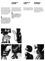
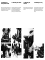
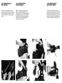
1
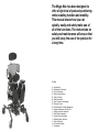
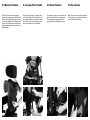
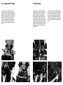
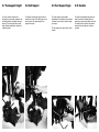
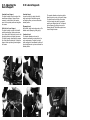
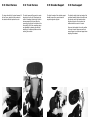
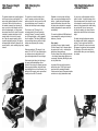
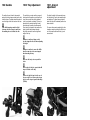
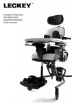
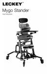
Mygo Max
User Instructions
The Mygo Max has been designed to
offer a high level of postural positioning
while enabling function and mobility.
This manual shows how you can
quickly, easily and safely make use of
all of the functions. The instructions on
safety and maintenance will ensure that
you will enjoy the use of the product for
a long time.
Contents
01 Intended Use
02 Declaration of Conformity
03 Terms of Warranty
04 Product History Record
05 Product Training
06 Safety Information
07 How to Unpack and Assemble
08 Fitting the Covers
09 Clinical Setup for Postural Management
10 Frequent Adjustments for Daily Use
11 Cleaning and Care Information
12 Daily Product Inspections
13 Annual Product Inspections
14 Reissuing Leckey Products
15 Product Servicing
16 Technical Information
17Accessories
6 Safety Information
1. Intended Use
The Mygo Max is an activity chair which
has been designed for children and young
adults with disabilities for use at home or
in the school environment. It is suitable
for clients aged 12 -18 years. The seating
system has a maximum user weight of
85kg. The seating system is modular
and can be used with a choice of indoor
or outdoor chassis. The Hi-low chassis
has been designed for use indoors but
can also be used outdoors on a level
surface. The Hi-low chassis should never
be exposed to the elements as this may
corrode the metal components.
5. Product Training Record
(Parents, Teachers & Carers)
Your Leckey product is a prescribed Class
1 Medical Device and as such Leckey
recommend that parents, teachers and
carers using the equipment should be
made aware of the following sections
of this user manual by a technically
competent person:
2. Declaration of Conformity
James Leckey Design Ltd as manufacturer
with sole responsibility declares that the
Mygo Max conforms to the requirements
of the 93/42/EEC Guidelines, Medical
Device Regulations 2002 and EN12182
Technical aids for disabled persons and
test methods.
Section 12
Cleaning and Care
3. Terms of Warranty
The warranty applies only when the
product is used according to the
specified conditions and for the intended
purposes, following all manufacturers’
recommendations (also see general terms
of sales, delivery and payment). A two
year warranty is provided on all Leckey
manufactured products and components.
4. Product History Record
Your Leckey product is classified as
a Class 1 Medical device and as such
should only be prescribed, set up
or reissued for use by a technically
competent person who has been trained
in the use of this product. Leckey
recommend that a written record is
maintained to provide details of all
setups, reissue inspections and annual
inspections of this product.
Section 6 Safety Information
Section 11
Frequent Adjustments for Daily use
Section 13 Daily Product Inspection
Leckey recommend that a written record
is maintained of all those who have been
trained in the correct use of this product.
6.1 Always read instructions fully before 6.8 When the seat is in use on a Hi-low
chassis please ensure that the height
use.
adjustment pedal and tilt in space lever
are locked off and cannot be adjusted
accidentally by other children.
6.2 To improve safety we recommend
that users should not be left unattended
at any time whilst using Leckey
6.9 When the Leckey seating systems
equipment.
are used on the Hi-low chassis we do not
recommend that users are moved over
uneven surfaces when in the equipment.
6.3 Only use Leckey approved
All due care and attention should be
components with your product. Never
taken if transporting in and out of the
modify the product in any way. Failure
to follow instructions may put the user seat.
or carer at risk and will invalidate the
warranty on the product.
6.10 Never leave the product on a
sloping surface, greater than 5 degrees.
6.4 If in any doubt to the continued safe Always remember to lock all the castors.
use of your Leckey product or if any
parts should fail, please cease using
6.11 Only use the push handle to steer
the product and contact our customer
and move the seat from one area to
services department or your local
another. Never use the tray for this
dealer as soon as possible.
purpose.
6.5 Carry out all positional adjustments
and ensure that they are securely
fastened before you put the user into
the product. Some adjustments may
require the use of a tool which is
provided with each product. Keep all
tools out of reach of children.
6.6 When putting the user into a seating
system, both for positional and safety
reasons, always secure the Leeway
Pelvic Cradle first.
6.7 When the product is stationary
ensure that all castors are locked and
facing away from the base, as this
will improve product stability. This is
especially important when the tilt in
space or back recline facility is in use.
6.12 The product contains components
which could present a choking hazard
to small children. Always check that
locking knobs and bolts within the
child’s reach are tightened and secure
at all times.
6.13 Leckey products comply with fire
saftey regulations in accordance with
EN12182. However the product contains
plastic components and therefore should
be kept away from all direct sources of
heat including naked flames, cigarettes
and gas heaters.
6.14 Do not place objects hotter than
40oC on the tray.t is in use on a Hi-low
chassis please ensure that the height
adjustment pedal and tilt in space lever
are locked off and cannot be adjusted
accidentally by other children.
6.15 Clean the product regularly. Do
not use abrasive cleaners. Carry out
maintenence checks on a regular
basis to ensure your product is in good
working condition.
6.16 The product is designed for
indoor use and when not in use should
be stored in a dry place that is not
subjected to extremes of temperature.
The safe operating temperature range
of the product is +5 to +40 deg Celsius.
6.17 Always check the plastic hand
knobs on the push handle are tightened
securely before you move the seat unit.
6.18 Before using the seating system
always check that the interface handle
on the seat unit is fully engaged
with the chassis. If the handle is not
engaged properly the seat unit may
come loose and could cause serious
injury to the child or carer.
How to
unpack and
assemble
the seating
system
7
Check parts
Congratulations on purchasing your
Mygo Max System. All of the parts will be
contained in polythene bags with each one
clearly labelled. Carefully remove them from
the boxes and check all the parts you have
ordered.
Keep polythene bags away from
children.
Some of the accessories will need to be
assembled before you attach the seat to the
base you have purchased.
Multi-tool
A number of adjustments will require the use
of the multi-tool, which is supplied with each
seat and can be found in the back pocket of
the seat.
7.1 Setting the
footrests
7.2 Attaching the
seating system to the
Hi-low chassis
Open up the angle of the leg supports by
unscrewing the knobs (A), shown, and set to
the maximum width. Open the socket caps
(B) and slide in the calf supports. Set to the
desired position, with the footplates facing
forward and retighten the socket cap bolts
with the multi-tool.
Adjust the height of the chassis to its
maximum to reduce risk of back strain while
attaching the seat unit. Refer to Section 11
on how to adjust the height of the chassis
you have purchased.
Always make sure the foot plate is
attached firmly.
A
B
First release the safety locking pin at the
front of the seat. To do this pull the pin out
and rotate through 90 degrees. Carefully lift
the seat and place it into the chassis. At the
rear of the underside of the seat you will see
a receiving channel. Place this securely over
the tube towards the back of the chassis.
Pull the handle at the front of the seat unit up
and then pivot the seat forward and down.
Once the front of the seat is lowered fully,
release the handle and push it forward to
ensure it has fully engaged on the front tube.
Rotate the safety locking pin so it engages in
front of the handle. If it hits the handle then
the seat is not inserted properly. Remove
and repeat process outlined above.
Always check the handle and locking
pin are fully engaged before you place
the child in the seating system. If the
handle is not engaged properly the seat
unit can come loose and could cause
serious injury to the child or carer.
7.3 Attaching the
push handle
7.4 Attaching the
headrest
7.5 Attaching the
lateral supports
The push handle is attached to the seatbase
by inserting the two lower stems into the
receiving tubes as shown. Secure the handle
in place by tightening the locking knobs (a).
To attach the head support slide the stem
into the receiving bracket. Set to the desired
position and secure using the hand lever (a).
While holding the components together,
remove the screw and washer. Align the
plastic angle adjuster mouldings and lateral
bracket with the slot in the backrest and refit
the washer and plastic screw.
Check these regularly to make sure the
knobs are tight, particularly if you are
moving the product unit along corridors
that may have uneven or sloping
surfaces.
A
7.6 Attaching the
Leeway Pelvic Cradle
7.7 Attaching the sandals
7.8 Attaching the
armrests
7.9 Attaching the Tray
Fasten the front buckle and side.Velcro tabs
of the Leeway Pelvic Cradle. Attach the four
side release buckles (a), two at the back of
the seatbase and two at the side.
If sandals are required they can be attached
to the footplates with a single fixing bolt.
To position the sandals simply loosen the
knob (a) under the footplate, select the
position you require and re-fasten the knob.
Slide the armrest into the receiving bracket.
Adjust to the required height and retighten
the knob.
The tray is attached to the seat by inserting
the tray tubes through the centre of each
armrest. Once the tray is located in the
position the knob (a) should be tightened
securely.
A
A
A
7.10 Attaching the
Hip Laterals
7.11 Attaching the
ankle huggers
7.12 Attaching the
protraction pads
To attach the hip laterals to the sacral
support, loosen screw (a) and insert the bar
of the hip lateral into the hole on the side
of the sacral support. Tighten the screw to
secure.
Slide the webbing through the slot in the
sandal. Loop the webbing back up and
through the bottom of the triglide. Then pass
the webbing through the top of the triglide.
Finally to lock the webbing in place, pass it
through the bottom of the triglide again.
Trim strap to required length.
To attach the protraction pads, remove
screw (a) from metal bracket on the standard
lateral. Place the protraction pad on top of
the bracket and replace with the new longer
screws which are included. Retighten using
the allen key. Attach to the seat as per 7.5.
1
A
3
2
4
A
Fitting
the
cushions
8
8.1 Femoral cushions
8.2 Seat base cushion
Slide a femoral cushion onto each of the
femoral supports and secure them by
pressing down on the poppers on either side.
The seat base cushion can be attached by
simply setting it in place and securing the
two popper tabs (a) at the back of the seat
base. To secure further hook the elastic tabs
to the hooks (b) underneath the seat base.
Always check the seat base cushion is
secure before placing the child in the seat.
A
B
8.3 Backrest Cushion
8.4 Leeway Pelvic Cradle
8.5 Sacral Cushion
8.6 Hip Laterals
First of all loosen the shoulder support
laterals with the allen key provided. Slide the
cushion over the laterals and secure using
the two snap fasteners. Slide the flaps over
the top of the backrest and underneath the
bottom of the backrest and secure with the
snap fasteners.
Fasten the Leeway Pelvic Cradle and place
on the seat base cushion. Press Velcro onto
the seat base cushion and attach four straps
(a) to secure. There are two camlocks at the
back of the seat and one on either side.
Fit the sacral cushion over the hardware and
fasten at the back with the snap fasteners.
The standard sacral support should be
attached with the double flaps at the top.
Slide the cushion covers over the hip lateral
with the open zip on the outside. Close the
zip and secure the Velcro flap.
8.7 Trunk Harness
8.8 Lateral Supports
8.9 Chest Harness
8.10 Headrest cushion
Slide each of the four straps (b) through
each of the camlock brackets and secure
by pushing down on the camlocks. Then
connect the shoulder straps (c) into the two
camlocks at the top and two at the side.
Slide the cushion covers over the lateral
support with the open zip on the outside.
Feed the plastic buckle through the slot
in the cover, close the zip and secure the
Velcro flap.
The chest harness can be attached by
clipping the male buckle (a) into the female
buckle (b) at either side of the lateral
supports.
Place the cushion onto the head support.
Snap the central fastener and two side
fasteners in place. Bring the lower flap under
the head support and attach the Velcro.
B
A
C
B
8.11 Padded Tray Insert
Slide the tray into the padded tray insert and
secure the six snap fasteners. Two at the
top, two at the bottom and two at the sides.
Clinical
Setup for
Postural
Management
9
9.1 Leeway Pelvic Cradle
9.2 Hip Lateral
The Leeway Pelvic Cradle should be flat
and open when the user is placed into the
Mygo Max. All four side and starps should be
already attached to the seat. First fasten the
buckle (a) at the front of the Leeway Pelvic
Cradle. Then fasten the Velcro (b) at the
sides to fit the Leeway Pelvic Cradle to the
user. Then adjust the front and rear straps
(c) and (d) to secure to position the user’s
pelvis.
The hip laterals can be width and angle
adjusted to suit the user’s requirements.
Loosen the screws (a) at the back of the
sacral support. Move the hip laterals to
required position. Ideally the hip laterals
should always be rotated so they rest on
top of the seat cushion even if the backrest
or sacral support is angled. Once the hip
laterals are in position, retighten the screws
securely. The laterals can also be angled
to help support, abduction adduction or
windsweeping.
To adjust the angle of the hip laterals loosen
the screw (b) on the hinge of the hip lateral.
Adjust to the required angle and retighten
the screw. The pads can also be adjusted
in depth and a small degree of rotation by
loosening the screws (c) on the pad, sliding
it to the required position and retighten the
screws.
A
C
B
C
A
D
B
9.3 Backrest Height
9.4 Backrest Angle
9.5 Adjusting the upper
leg supports
9.6 Adjusting the
femoral guides
To adjust the overall height of the backrest
loosen the two screws in the middle of the
backrest, adjust to the required position and
retighten securely. The height can be fine
tuned with the user in the seat.
To change the angle loosen the screw at the
bottom of the backrest spine, adjust to the
required position and retighten the screw
securely.
The upper leg supports will be set at the
minimum position on arrival. Set the depth
before placing the child in the seat. Fine
adjustment is possible afterwards but is
restricted by the user’s weight. To achieve
the correct position measure the length from
the child’s lower back to the back of their
knee.
To adjust the width of the femoral guides.
Loosen the screws (a) and position as
required. Retighten the screws. There are
two screws per femoral guide.
Use caution when adjusting to minimum
setting as fingers could become trapped
between moving and static parts.
The backrest angle can be adjusted with the
user in the seat. The backrest spine has a
useful angle indicator designed to indicate
the preferred position or back angle for
different activities.
Hold the backrest spine with one hand
while you adjust the back angle.
Adjust the supports to the desired position
using the two knobs underneath the seat
base. To adjust, loosen the knobs, slide to
the desired position and retighten. Keep the
supports pointing straight forward at this
time unless wind sweeping or adduction,
abduction must be accommodated, in which
case set the angle accordingly using the
knobs again.
A
9.7 Footsupport Height
9.8 Calf Support
9.9 Foot Support Angle
9.10 Sandals
To raise or lower the height of the
footsupport, loosen screw (a) adjust to the
required position and retighten the screw
securely. The foot support has a useful
height indicator designed to indicate the
preferred position,
To adjust the calf support angle, loosen the
screw (b) at the top of the calf support, move
front or back to the required angle, then
retighten the screw.
To set the angle to accommodate
plantarflexion or dorsiflexion, simply loosen
or tighten the screw (a) to select the angle
you require.
To position the sandals simply loosen the
knob (a) under the footplate, select the
position you require and re-fasten the knob.
To position the user’s feet in the sandals
secure the Velcro ankle and toe straps
provided.
The foot supports can simply flip up to aid
transfer.
B
A
A
A
9.11 Adjusting the
Sacral Support
9.12 Lateral Supports
Standard Sacral Support
To adjust the height, depth or angle of the
standard sacral support, loosen the two
screws (a) on either side of the bracket,
move to the required position and retighten
the screws.
Standard laterals
Loosen the bolts (a) to adjust the width,
height and angle of the lateral supports
and retighten when you have achieved the
desired position.
Ball & Socket Sacral Support
To adjust the height or depth of the ball &
socket sacral support, loosen each screw
(a) on either side of the bracket, move to the
required position and retighten the screws.
To adjust the angle, loosen both the screws
(b) on the ball and socket joint. Position the
support at the required angle and retighten
the screws.
Flipaway laterals
Adjust width, height and angle as above. The
laterals can be flipaway by pulling pin (b).
The complex laterals can also be angled to
allow the pad to contour to the user’s shape.
To adjust loosen the bolt (a) at the centre
of the pad, angle the pad to the required
position and retighten the bolt. The laterals
can be flipaway by pulling pin as per the
flipaway laterals. The lateral supports have
a useful height indicator.
Complex laterals
The complex laterals can be used in
whatever combination is most suited to the
user’s requirements. To adjust the height
width and angle of these laterals, loosen bolt
(a) and retighten when you have achieved the
desired position.
A
A
A
A
B
B
9.13 Chest Harness
9.14 Trunk Harness
9.15 Shoulder Support
9.16 Head support
To change the width of the chest harness, lift
the front cover, adjust the Velcro straps to
the desired width and replace the cover.
The trunk harness will be open but remain
attached by the clip (a). When placing the
child in the seating system bring the trunk
harness across the front and attach by
connecting the clip into the buckles on the
other side (b). All of the connecting straps
are adjustable by releasing the camlock,
adjusting to the desired position and then
securing the camlock.
To adjust the angle of the shoulder support
laterals, loosen screw, move laterals to
required angle and retighten.
To adjust the height, depth and angle of the
contoured headrest, loosen the hand knobs
(A) and when set to the desired position
retighten the knobs. Do not remove the
headrest while the user is in the seat.
Never use the headrest to force the position
of the user’s head. Always use caution to
ensure fingers do not become trapped when
adjusting the headrest
A
B
A
9.17 Armrest adjustment
9.18 Tray Adjustment
To adjust the height of the armrest loosen
the hand knob (b), set to the desired height
and retighten. To adjust the angle, rotate
ratchet handle (a) until the desired position
has been achieved.
The height and angle of the tray are set by
adjusting the armrests as detailed above. To
remove or adjust the depth of the tray loosen
the knobs (a) under the armrest, set to the
desired position and re-tighten securely.
Always use caution as fingers could become
trapped in the slot when adjusting the height.
Always use caution to ensure the child’s
hands or arms do not become trapped
when inserting the tray.
Never use the tray to steer or push the
chair.
Do not place objects, hotter than 40
degrees Celsius on the tray.
Please note that the tray is for the use of
the user only. Do not lean or place objects
on the tray, greater than 8kgs (17.6lbs).
B
A
A
Frequent
adjustment
for daily use
(therapists/
carers/parents)
Parents and carers should be
shown how to make frequent
adjustments and be made aware
of the safety checks in Section
6 by a technically and clinically
competent person who has been
trained in the use of the product.
Leckey recommend that a written
record is maintained of all parent
and carers who have been trained
in the use of this product.
10
10.3 Chassis
10.1 Transferring your
child into and out of the
seat
10.2 Adjusting the
Leeway Pelvic Cradle
Before transferring the child into the seat
carry out the daily product inspection as
outlined in section 13 of this user manual.
Adjust the seat to a comfortable height
to facilitate transfer. Lock all the castors,
ensuring that they are facing outwards
to maximise product stability. Make sure
the safety buckle on the chest harness is
released and is out of the way to facilitate
transfer.
The correct positioning and tensioning
of the Leeway Pelvic Cradle is key to a
child’s postural management, affecting their
comfort and ability to carry out activities.
Please consult with your therapist to ensure
the Leeway Pelvic Cradle is positioned
correctly and that the straps are tensioned
appropriately.
To tension the Leeway Pelvic Cradle use the
4 side straps (c) and the velcro tabs (d).
If using the seat outdoors and your child is
wearing a coat, position the Leeway Pelvic
Cradle under the coat.
To prepare the Hi-low chassis for the seating
system we recommend that you raise the
chassis to a comfortable working height
by pressing the foot lever at the rear of the
chassis or by pressing the up button on the
handset of the powered option.
If the seat has flip-away thoracic laterals,
first move these out of the way using knob
a. Unclip the Leeway Pelvic Cradle in the
middle, undo the side velcro of the Leeway
Pelvic Cradle and allow the harness to open
out to facilitate transfer. Lastly if sandals are
fitted open the straps. You are now ready to
transfer or hoist the child into the seat. The
Leeway Pelvic Cradle is fastened using the
middle buckle, and side velcro.
Always secure the Leeway Pelvic Cradle
first before fastening other buckles or
harnesses. Adjust the harness so the child
cannot slide or creep forward in the seat.
C
C
The Mygo Max is designed to fit onto a
range of chassis. This user manual shows
the correct and safe use of the seating
system with the Leckey Hi-low chassis. For
all other chassis or bases please refer to the
manufacturer’s handbook.
D
10.4 Powered height
adjustment
10.5 Charging the
battery
The powered chassis can be easily adjusted
with the push button control handset. The
seat can be height adjusted with the client
in the chair. When one of the buttons on
the handset is pressed, then the seat will
move up or down in that direction until the
button is released again, or if the actuator
has reached the end of its stroke.The system
is started by inserting the battery into the
circular holder in the end of the control
box. Clean the magnetic poles for all dirt
or metal chips before inserting. The battery
will magnetically hold itself in place with the
correct position , and a confirming long beep
is heard.
The control box checks the battery level
every 24 seconds, and when the battery
reaches a low limit, then the control box will
give a double-beep every 24 seconds to
indicate that the battery needs recharging.
This is done in the ”C3-charger”, full
re-charging takes 5-8 hours, depending
on state of charge. To remove the battery,
turn it 90 degrees (right- or left) to release it
from the magnets . The battery (NiMH-type)
can be recharged from any state of charge
without reducing battery life or batterycapacity.
When connecting the ”C3-charger” to the
mains (100 – 240 V AC), the red diode lights
up continuously and a single flash in the
green diode appear before it turns off again.
When inserting the battery into the charger,
the green diode starts flashing with an
interval of 1/sec during the charging process.
When charging is finishing, the green diode
stops flashing and turns on continuously, the
battery is fully charged, can be removed and
is ready for use in the C3 controller.
10.6 Height Adjustment
– Hi-low Chassis
Repeated runs at a high rate with heavy
loads, may create overheating inside the
battery – a safety interlock-temperature
sensor will disconnect the power. When
the battery has cooled down to accepted
working temperature the power switch on
automatically.
To secure long lifetime of NiMH batteries, it
is recommended to recharge the battery at
least every 3 months.
Beep signals:
Long beep: Power on (battery inserted)
Two short beeps: Every 24 seconds (when
the system is not in use): = indicating low
battery level, please recharge.
Two short beeps: When starting the actuator
= low voltage, please change battery soon,
or recharge—the battery will still give power,
but only limited time.
Long beep: When running the actuator =
battery lower than 17,6Volt (only down/in
movement will be accepted thereafter)
Continuous short beeps: (Temperature inside
control box too high, please take a break)
You can carry out this adjustment with the
child in the chair. To adjust the height of the
Hi-low chassis press the foot lever at the rear
of the chassis or press the up button on the
handset of the powered option whilst holding
the push handle. Once you remove your
foot from the pedal or your thumb from the
handset the seat will be fixed at the chosen
height.
For safety the height adjustment pedal on
the chassis can be locked by engaging the
pull pin (C) on the right hand side of the
pedal. To unlock pull the pin out and rotate
90 degrees, the pedal can then be operated.
The locking pin (C) should be kept in the
locked position when you are not adjusting
the chassis.
Always keep the locking pin engaged
when you are not adjusting the chassis.
This will prevent the foot pedal being
operated accidentally.
Always use caution as hands could
become trapped when height adjusting
the base.
10.7 Tilt in space
10.8 Chest and Trunk
Harness Adjustment
The tilt in space can be angled while the
user is in the seat. Before you adjust the tilt
in space angle of the seat always ensure the
pelvic harness is secured preventing the user
from sliding forward in the seat.
If the child requires chest support as part
of their postural support programme the
seat will be fitted with rigid laterals or a
combination of laterals, chest harness
and trunk harness. These may need to be
adjusted on a daily basis to accommodate
differences in clothing.
Please refer to section 9.14 for specific
guidance on adjusting the trunk harness.
Always check with your therapist as to the
optimum positioning and tensioning of the
straps and support items for the child.
Check the harness and laterals are secure
to ensure the child is safe and cannot
slide forward in the seat as this may
restrict their breathing.
To adjust the tilt angle pull the lever on
the push handle. Once you have selected
the angle you require, by simply removing
your hand from the handle, the chair will be
locked in position.
Please use handle bars when operating tilt
in space.
Always check with your therapist that
the use of tilt in space will not cause any
obstructions
A
A
To change the width of the chest harness, lift
the front cover, adjust the Velcro straps and
set to the desired width. When the correct
width has been achieved replace the cover.
Always make sure the plastic buckles
are fully engaged when using the chest
harness.
10.9 Sandals
10.10 Tray Adjustment
10.11 Armrest
adjustment
To position the user’s feet in the sandals
secure the Velcro straps provided so the foot
is held in place. The straps should be placed
over the bridge of the foot and over the toes.
The activity tray can be used for a range of
functions and its position can be fine tuned
to suit the user and the activity whether it
is for fun, education or feeding. The tray is
attached to the seat by inserting the tray
tubes through the centre of each armrest.
Once the tray is located in the position the
knob (a) should be tightened securely.
Adjust the armrests to set the height and
angle of the tray.
To adjust the height of the armrest loosen
the hand knob (b) set to the desired height
and retighten. To adjust the angle rotate
hand knob (a) until the desired position has
been achieved.
If the child is wearing sandals or light
footwear check the straps to make sure
the webbing does not irritate the skin.
To remove the armrest completely for side
transfer or assist in getting the child into or
out of the seat loosen hand knob (c), and
remove knob.
Always use caution as fingers could
become trapped in the slot when adjusting
the height.
Always use caution to ensure the child’s
hands or arms do not become trapped
when inserting the tray.
Never use the tray to steer or push the
chair.
Do not place hot objects, greater than 40
degrees Celsius on the tray.
Please note that the tray is for the use of
the user only. Do not lean or place heavy
objects on the tray, not greater than 8kgs
(17.6lbs).
A
C
B
A
11 Cleaning & Care
How to Maintain
When cleaning we recommend that you use
only warm water and a non-abrasive
detergent. Never use organic solvents or dry
cleaning fluids.
Upholstery and fabrics
1. The cushion covers can be removed,
machine washed at 40ºC and tumble dried at
a low temperature.
All other soft upholstery can be placed into
the washing machine intact, after removing
bolts and fastenings.
2. The upholstery and fabrics can also be
cleaned by hand whilst in place. When
cleaning we recommend that you use only
warm water and a non-abrasive detergent.
3. Staining should be removed as quickly
as possible with absorbent cloth, towels or
a sponge. Routine soap and warm water
sponging is effective for ordinary soiling
and minor spills. Be careful not to over wet
the fabric as this will cause the stainingto
spread.
4. Antiseptic cleaning agents can be used
on more stubborn stains. These may require
a safe solvent such as Isopropyl Alcohol or
Mineral Spirit. A half cup of household bleach
to 5 litres of water can also be used as a
useful disinfectant.
5. The Leeway Pelvic Cradle and trunk
harnesses can be machine washed at 40
Deg C. Make sure all bolts and fasteners are
removed first as they may cause damage to
your washing machine. Store these in a safe
place and out of reach from children.
6. Always ensure the product is dry before
use.
12 Daily Product
Inspection
Metal and plastic components
1. Soap and water or antibacterial spray can
be used for daily cleaning.
2. For deep cleaning a low pressure steam
cleaner can be used.
3. Do not use solvents to clean plastic or
metal components.
4. Make sure the product is dry before use.
(Therapists, parents & carers)
We recommend that daily visual checks of
the equipment are carried out by therapists,
carers or parents to ensure the product is
safe for use. The recommended daily checks
are detailed below.
1. C
heck that there is no lateral movement or
wobble in any of the moving parts. Ensure
all adjustment knobs and bolts are in place
and secure.
2. C
heck all upholstery and Velcro for signs
of wear and tear.
3. C
heck all castors are moving freely and
lock securely.
4. E
nsure the handle and locking pin on the
seat interface plate is fully engaged and
the seat unit is securely fixed onto the
chassis.
5. E
nsure the Leeway Pelvic Cradle is fully
secured around the user and they cannot
slide or creep forward in the seat.
6. Ensure the footplate is attached securely.
If in any doubt to the continued safe
use of your Leckey product or if any
parts should fail, please cease using
the product and contact our customer
service department or your local dealer
as soon as possible.
13 Annual Product
Inspection
14 Re-issuing Leckey
Products
(Therapist, Technician, Leckey Product
Advisor, Dealer)
Leckey recommend that each product should
be subject to a detailed inspection at least
once a year and every time the product is
reissued for use. This inspection should
be carried out by a technically competent
person who has been trained in the use of
the product and should include the following
checks as a minimum requirement.
6. Lift the base to check each castor
individually. Make sure they are moving freely
and remove any dirt from the rubber wheels.
Check that the brakes lock the wheels
securely
1.Check that there is no lateral movement or
wobble in any of the moving parts. Ensure all
adjustment knobs and bolts are in place and
secure.
8.Leckey recommend that a written record is
maintained of all annual product inspections.
2.Check all ratchet handles, knobs, nuts,
bolts and plastic buckles are in place,
replacing any missing items. Paying
particular attention to the following items;
> Headsupport locking bolts.
> Backrest height and angle adjustments
bolts.
> Seat depth adjustment bolts.
> Leeway Pelvic Cradle / hip guide
attachment bolts.
> Footrest height and angle adjustment.
3.Check the chassis height adjustment
mechanism is working properly. If the
chassis is foot pedal operated ensure the
seat height doesn’t change when the pedal
is released. Also, check that the locking
pin engages securely to prevent accidental
height adjustment of the chassis.
4.Adjust the seat to its maximum range of
tilt in space and ensure that the locking lever
locks the seat out securely at varying point in
this range.
5.Check that where the seat and chassis join
there is no visible wear and tear on the metal
components.
7.Visually check the structure of the product
paying attention to weld points on the frame
ensuring there are no signs of fatigue or
cracking around the welds.
If in any doubt to the continued safe
use of your Leckey product or if any
parts should fail, please cease using
the product and contact our customer
service department or your local dealer
as soon as possible.
Most Leckey products are assessed and
ordered to meet the needs of an individual
user. Before reissuing a product we
recommend that the therapist prescribing
the product has carried out an equipment
compatibility check for the new user and has
ensured that the product being re-issued
contains no modifications or special
attachments.
A detailed technical inspection should be
carried out on the product prior to re-issuing.
This should be carried out by a technically
competent person who has been trained in
the use and inspection of the product. Please
refer to section 11 for the required checks to
be carried out.
Ensure the product has been cleaned
thoroughly in accordance with section 12 of
this manual.
Ensure a copy of the user manual is supplied
with the product. A copy can be downloaded
from our website www.leckey.com
Leckey recommend that a written record is
maintained of all product inspections carried
out during the reissue of the product.
If in any doubt to the continued safe
use of your Leckey product or if any
parts should fail, please cease using
the product and contact our customer
service department or your local dealer
as soon as possible.
15 Technical Information
Product and
161-600
161-900-02
161-900-03
161-900-04
161-900-15
Accessory Codes
Mygo Max Seat Shell
Seat Cushion Pack - Orange
Seat Cushion Pack - Blue
Seat Cushion Pack - Pink
Seat Cushion Pack - Grey
Chassis
161-693
161-679
Hydraulic Hi-Low Base
Powered Hi-Low base
Accessories
161-688Armrests
152-3600Sandals
161-610
Lower Leg Supports
161-689
Flipaway lateral supports
161-690
Complex lateral supports
161-691
Protraction pads with lateral supports
161-692
Angle adjustable sacral pad
161-608
Large femorals
161-967
Padded tray cover
161-961
Memory foam cushion pack
161-695Tray
147-2600 Leeway Pelvic Cradle Size 2
147-2610
Leeway Pelvic Cradle Size 3
155-LEC-002 Fitting kit for Harness
155-N001-L Large Trunk Harness
161-696
Side Pads
Mygo seat dimensions
Size
Size 3
Age
12 - 18
Max User Weight
85
Seat Depth
Min 410mm / 16.4 inches
Max 560mm / 22.4 inches
Seat Width
Min 345mm / 13.8 inches
Max 500mm / 120 inches
Chest Width
Min 170mm / 6.7 inches
Max 270mm / 10.6 inches
Back Height
Min 330mm / 13.2 inches
Max 510mm / 20.4 inches
Seat to Sandal
Min 330mm / 13.2 inches
Max 510mm / 20.4 inches
Plantarflexion / Dorsiflexion
10° to 10°
Back Angle
+10° to -25°
Windsweeping up to
20°
Calf Angle
-15° to +30°
Tilt in Space
+10° to -25°
Armrest
Min 360mm / 14.2 inches
Max 700mm / 27.5 inches
Actuator specification- 500055+493312020000
Rated IP66
Duty Cycle Max 10% or 2 min continuous
use followed by 18 min not in use.
Operation temperature -5degC to +70degC,
storage temperature -40degC to +70degC.
Push/pull Max 4500N
Self Lock at 4500N Push/Pull Typical speed
with full load 6,0mm/sec Max amps at load
of 4500N is 8 amps
Power input voltage 24v +- 10%
Battery Box – C3BAT Rated IP51
Type: NiMH
Power supply: 24V DC
Maximum continuous current: 7A (short time
peak current 10-20A)
Capacity: 1400mAh
Low-capacity warning: Sound signal
Handset – C3REMOX incl. foil Rated IP51
Control Ambient temp +5deg to +40deg C
Battery Charger – C3CHAR
Power supply: 110-240V AC
Charging time: 5-8 hours
Mains connector: European/UK/US type
Battery change: Easy revolving fastening
Charging signal: Green light flashing
Full capacity signal: Continous green light
Products may be stored in non-heated
storage facilities with humidity between
0 and 100%, none condensing. None
condensing means that one should not take
a product from an ice cold warehouse into a
room with a temperature of 20deg C;
if this is done then moistness will appear on
the products.
Leckey
19 Ballinderry Road
Lisburn
BT28 2SA
Northern Ireland
United Kingdom
T: 028 9260 0750
F: 028 9260 0799
E:[email protected]
W:www.leckey.com
Stephen
24 hour postural
care for babies,
kids & adults.
Sleeping, Sitting,
Standing, Walking,
Moving, Bathing,
Toileting.
LS314-01