1
mg/L
C
YSI Model 85
Handheld Oxygen,
Conductivity, Salinity,
and Temperature
System
Operations
Manual
CONTENTS
SECTION 1 Introduction....................................................................................................................1
SECTION 2 Preparing The Meter....................................................................................................3
2.1
2.2
2.3
2.4
2.5
2.6
Unpacking.............................................................................................................................3
Warranty Card.......................................................................................................................3
Batteries ................................................................................................................................3
Calibration/Storage Chamber...............................................................................................5
Hand Strap ............................................................................................................................5
The Meter Case.....................................................................................................................5
SECTION 3 Preparing The Probe....................................................................................................7
3.1 Membrane Cap Installation ................................................................................................7
SECTION 4 Overview Of Operation................................................................................................9
SECTION 5 Calibration...................................................................................................................11
5.1 Calibration of Dissolved Oxygen.......................................................................................11
5.2 Calibration of Conductivity................................................................................................12
SECTION 6 Advanced Conductivity Setup...................................................................................15
6.1 Changing the Temperature Coefficient..............................................................................15
6.2 Changing the Reference Temperature ...............................................................................16
6.3 Changing from Autoranging to Manual Ranging .............................................................16
SECTION 7 Making Measurements ..............................................................................................17
7.1
7.2
7.3
7.4
Turning the Instrument On.................................................................................................17
The Measurement Modes of the Model 85........................................................................17
Autoranging and Range Searching ....................................................................................18
The Backlight......................................................................................................................18
SECTION 8 Saving Data...................................................................................................................21
8.1 Saving Data to Memory .....................................................................................................21
8.2 Recalling Stored Data.........................................................................................................21
8.3 Erasing Stored Data............................................................................................................22
SECTION 9 Maintenance ................................................................................................................23
9.1 Cleaning and Storage..........................................................................................................23
SECTION 10 Principles Of Operation............................................................................................25
10.1 Temperature Effect on Conductivity ...............................................................................25
i
SECTION 11 Discussion Of Measurement Errors........................................................................27
11.1 Dissolved Oxygen Measurement Errors..........................................................................27
11.2 Conductivity Measurement Errors...................................................................................29
11.3 Dissolved Oxygen Probe Precautions..............................................................................31
SECTION 12 Troubleshooting .........................................................................................................33
SECTION 13 Warranty And Repair...............................................................................................35
SECTION 14 Accessories And Replacement Parts .......................................................................40
APPENDIX A
APPENDIX B
APPENDIX C
APPENDIX D
APPENDIX E
APPENDIX F
Specifications ............................................................................................................45
Required Notice ........................................................................................................47
Temperature Correction Data ...............................................................................51
Conversion Chart.....................................................................................................53
Oxygen Solubility Table ..........................................................................................52
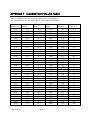
Calibration Values Table.........................................................................................54
ii
SECTION 1
INTRODUCTION
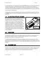
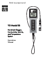
The YSI Model 85 Handheld Dissolved Oxygen, Conductivity, Salinity and Temperature System is
a rugged, micro-processor based, digital meter with an attached YSI combination conductivity and
dissolved oxygen probe.
The YSI Model 85 is designed for use in field, lab, and process control applications as well as for
environmental, aquaculture, and industrial uses. The Model 85 is available with cable lengths of
either 10, 25, 50 or 100 feet. The body of the probe has been manufactured with stainless steel to add
rugged durability and sinking weight. The probe also utilizes our easy to install cap membranes for
measuring dissolved oxygen.
The YSI Model 85 probe is a non-detachable, combination sensor designed specifically for the YSI
Model 85 Handheld System. The conductivity portion is a four-electrode cell with a cell constant of
5.0/cm ±4%. The dissolved oxygen portion is a polargraphic Clark type sensor.
The Model 85’s microprocessor allows the system to be easily calibrated for dissolved oxygen or
conductivity with the press of a few buttons. Additionally, the microprocessor performs a selfdiagnostic routine each time the instrument is turned on. The self-diagnostic routine provides you
with useful information about the conductivity cell constant and function of the instrument circuitry.
The system simultaneously displays temperature (in °C), along with one of the following
parameters: dissolved oxygen in either mg/L (milligrams per liter) or % air saturation; conductivity;
temperature compensated conductivity; (in µS/cm or mS/cm), and salinity (in parts per thousand
{ppt}).
The system requires only a single calibration regardless of which dissolved oxygen display you use.
The calibration of conductivity is not required but is available. A single calibration will adjust the
instrument, regardless if you are reading conductivity or temperature compensated conductivity.
You can switch between all of these parameters with the push of a single key.
A calibration\storage chamber is built into the instrument case. A small sponge in the chamber can
be moistened to provide a water saturated air environment that is ideal for air calibration of the
dissolved oxygen probe. This chamber also provides a convenient place to store the probe when the
system is not in use, and provides protection for the electrodes within the conductivity probe. The
Model 85 case is also waterproof (rated to IP65). You can operate your Model 85 in the rain without
damage to the instrument.
Six AA-size alkaline batteries power the instrument. A new set of alkaline batteries will provide
approximately 100 hours of continuous operation. When batteries need to be replaced, the LCD will
display a “LO BAT” message.
YSI, Incorporated
Model 85
1
Introduction
YSI, Incorporated
Section 1
Model 85
2
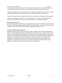
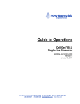
SECTION 2 PREPARING THE METER
2.1
UNPACKING
When you unpack your new YSI Model 85 Handheld Dissolved Oxygen, Conductivity, Salinity
and Temperature System for the first time, check the packing list to make sure you have received
everything you should have. If there is anything missing or damaged, call the dealer from whom
you purchased the Model 85. If you do not know which of our authorized dealers sold the system
to you, call YSI Customer Service at 800-765-4974 or 937-767-7241, and we'll be happy to help
you.
2.2
WARRANTY CARD
Before you do anything else, please complete the Warranty Card and return it to YSI. This will
record your purchase of this quality instrument in our computer system. Once your purchase is
recorded, you will receive prompt, efficient service in the event any part of your YSI Model 85
should ever need repair and we will be able to quickly verify the warranty period.
2.3
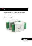
BATTERIES
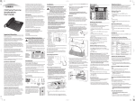
There are a few things you must do to prepare your YSI Model 85 for use. First, locate the six AAsize alkaline batteries that were included in your purchase. Use a screwdriver or a small coin to
remove the thumbscrew on the bottom of the instrument. This thumbscrew holds the batterychamber cover in place. The battery-chamber cover is marked with the words "OPEN" and
"CLOSE."
Hand strap
Battery chamber
cover
Thumb screw
Polarity marking
O-rings
YSI, Incorporated
Model 85
3
Preparing the Meter
Section 2
NOTE: On some models, the battery cover thumbscrew may be unscrewed by hand (a screwdriver
may not be required).
There is a small label inside each of the two battery-chamber sleeves. These labels illustrate the
correct way to install the batteries into each sleeve of the battery-chamber.
NOTE: It is very important that the batteries be installed ONLY as illustrated. The instrument will
not function and may be damaged if the batteries are installed incorrectly.
YSI, Incorporated
Model 85
4
Preparing the Meter
Section 2
Turn the instrument on by pressing and releasing the ON/OFF button on the front of the instrument.
The liquid crystal display (LCD) should come on. Allow a few seconds for the instrument to
complete its diagnostic routine. Notice that the instrument will display the specific cell constant of
the conductivity probe during this diagnostic routine. If the instrument does not operate, consult the
section entitled Troubleshooting.
You may also want to take the instrument into a dark room and with the instrument ON, hold down
the LIGHT button. The instrument backlight should illuminate the LCD so that the display can be
easily read.
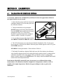
2.4
CALIBRATION/STORAGE CHAMBER
The Model 85 has a convenient calibration storage
chamber built into the instruments' side. This chamber
provides an ideal storage area for the probe during
transport and extended non-use. If you look into the
chamber you should notice a small round sponge in the
bottom of the chamber. Carefully put 3 to 6 drops of
clean water into the sponge. Turn the instrument over
and allow any excess water to drain out of the chamber.
The wet sponge creates a 100% water saturated air
environment for the probe, which is ideal for dissolved
oxygen calibration.
2.5
Calibration/Storage
Chamber
HAND STRAP
The hand strap is designed to allow comfortable operation of the Model 85 with minimum effort. If
the hand strap is adjusted correctly, it is unlikely that the instrument will be easily dropped or
bumped from your hand. See figure on previous page.
To adjust the hand strap on the back of the meter, unsnap the vinyl cover and pull the two Velcro
strips apart. Place your hand between the meter and the strap and adjust the strap length so that your
hand is snugly held in place. Press the two Velcro strips back together and snap the vinyl cover back
into place.
2.6
THE METER CASE
The meter case is sealed at the factory and is not intended to be opened, except by authorized service
technicians. Do not attempt to separate the two halves of the meter case as this may damage the
instrument, break the waterproof seal, and will void the manufacturer's warranty.
YSI, Incorporated
Model 85
5
Preparing the Meter
YSI, Incorporated
Section 2
Model 85
6
SECTION 3 PREPARING THE PROBE
The YSI Model 85 dissolved oxygen probe is shipped dry. The protective membrane cap on
the probe tip must be removed and replaced with KCl solution and a new membrane cap
before using the probe. Follow the instructions below to install KCl solution and the new
membrane cap.
3.1
MEMBRANE CAP INSTALLATION
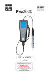
To install a new membrane on your YSI Model 85 dissolved oxygen probe:
1.
2.
3.
4.
5.
6.
Unscrew and remove the probe sensor guard.
Unscrew and remove the old membrane cap.
Thoroughly rinse the sensor tip with distilled water.
Prepare the electrolyte according to the directions on the KCl solution bottle.
Hold the membrane cap and fill it at least 1/2 full with the electrolyte solution.
Screw the membrane cap onto the probe moderately tight. A small amount of
electrolyte should overflow.
7. Screw the probe sensor guard on moderately tight.
Fill Membrane
with KCL Solution
Unscrew Guard
Unscrew Cap
Screw Cap on
moderately tight
YSI, Incorporated
Screw Guard on
moderately tight
Model 85
7
Preparing the Probe
YSI, Incorporated
Section 3
Model 85
8
SECTION 4 OVERVIEW OF OPERATION
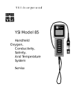
The following diagram is an overview of the operation of the Model 85. See the following sections
for details of operation.
YSI, Incorporated
Model 85
9
Overview of Operation
YSI, Incorporated
Section 4
Model 85
10
SECTION 5
5.1
CALIBRATION
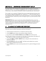
CALIBRATION OF DISSOLVED OXYGEN
To accurately calibrate the YSI Model 85 you will need to know the approximate altitude of
the region in which you are located.
1. Ensure that the sponge inside the instrument's
calibration chamber is wet. Insert the probe into
the calibration chamber.
2. Turn the instrument on by pressing the
ON/OFF button on the front of the instrument.
Press the MODE button until dissolved oxygen
is displayed in mg/L or %. Wait for the
dissolved oxygen and temperature readings to
stabilize (usually 15 minutes is required).
Calibration/Storage
Chamber
3. Use two fingers to press and release both the
UP ARROW and DOWN ARROW buttons at the same time.
4. The LCD will prompt you to enter the local altitude in hundreds of feet. Use the arrow
keys to increase or decrease the altitude. When the proper altitude appears on the LCD, press
the ENTER button once.
EXAMPLE: Entering the number 12 here indicates 1200 feet.
5. The Model 85 should now display CAL in the lower left of the display, the calibration
value should be displayed in the lower right of the display and the current % reading (before
calibration) should be on the main display. Make sure that the current % reading (large
display) is stable, then press the ENTER button. The display should read SAVE then should
return to the Normal Operation Mode.
Each time the Model 85 is turned off, it may be necessary to re-calibrate before taking
measurements. All calibrations should be completed at a temperature which is as close as
possible to the sample temperature. Dissolved oxygen readings are only as good as the
calibration.
YSI, Incorporated
Model 85
11
Calibration
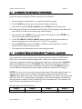
5.2
Section 5
CALIBRATION OF CONDUCTIVITY
IMPORTANT: System calibration is rarely required because of the factory calibration of the
YSI Model 85. However, from time to time it is wise to check the system calibration and make
adjustments when necessary.
Prior to calibration of the YSI Model 85, it is important to remember the
following:
1. Always use clean, properly stored, NIST traceable calibration solutions (see Accessories and
Replacement Parts). When filling a calibration container prior to performing the calibration
procedures, make certain that the level of calibrant buffers is high enough in the container to
cover the entire probe. Gently agitate the probe to remove any bubbles in the conductivity cell.
2. Rinse the probe with distilled water (and wipe dry) between changes of calibration solutions.
3. During calibration, allow the probe time to stabilize with regard to temperature (approximately
60 seconds) before proceeding with the calibration process. The readings after calibration are
only as good as the calibration itself.
4. Perform sensor calibration at a temperature as close to 25°C as possible. This will minimize any
temperature compensation error.
Follow these steps to perform an accurate calibration of the YSI Model 85:
1. Turn the instrument on and allow it to complete its self-test procedure.
2. Select a calibration solution that is most similar to the sample you will be measuring.
•
•
•
For sea water choose a 50 mS/cm conductivity standard (YSI Catalog# 3169)
For fresh water choose a 1 mS/cm conductivity standard (YSI Catalog# 3167)
For brackish water choose a 10 mS/cm conductivity standard (YSI Catalog # 3168)
3. Place at least 3 inches of solution in a clean glass beaker.
4. Use the MODE button to advance the instrument to display conductivity.
5. Insert the probe into the beaker deep enough so that the oval-shaped hole on the side of the probe
is completely covered. Do not rest the probe on the bottom of the container -- suspend it above
the bottom at least 1/4 inch.
6. Allow at least 60 seconds for the temperature reading to become stable.
7. Move the probe vigorously from side to side to dislodge any air bubbles from the electrodes.
8. Press and release the UP ARROW and DOWN ARROW buttons at the same time.
The CAL symbol will appear at the bottom left of the display to indicate that the instrument is now
in Calibration mode.
YSI, Incorporated
Model 85
12
Calibration
Section 5
10.00 µS
24.8 oC
CAL
9. Use the UP ARROW or DOWN ARROW button to adjust the reading on the display until it
matches the value of the calibration solution you are using.
10. Once the display reads the exact value of the calibration solution being used (the instrument will
make the appropriate compensation for temperature variation from 25°C), press the ENTER
button once. The word “SAVE” will flash across the display for a second indicating that the
calibration has been accepted.
The YSI Model 85 is designed to retain its last conductivity calibration permanently. Therefore,
there is no need to calibrate the instrument after battery changes or power down.
YSI, Incorporated
Model 85
13
Calibration
YSI, Incorporated
Section 5
Model 85
14
SECTION 6
ADVANCED CONDUCTIVITY SETUP
The default settings of the YSI Model 85 are appropriate for the vast majority of measurement
applications. However, some measurement applications require very specific measurement criteria.
For that reason, we have made the YSI Model 85 flexible to accommodate these “advanced users.”
If, for example, you are using the YSI Model 85 for a process control application that requires that
the conductivity readings be compensated to 20 oC instead of 25 oC -- this is the section to read. Or,
if your application for the YSI Model 85 involves the measurement of a very specific saline solution,
the default temperature coefficient may need to be changed to get the very best measurement of that
specific salt.
IMPORTANT: There is never a need to enter Advanced Setup Mode unless your special
measurement application calls for a change in reference temperature and or temperature coefficient.
Therefore, unless you are certain that your application requires a change to one or both of these
criteria, do not modify the default reference temperature (25oC) or the default temperature
coefficient (1.91%).
6.1
CHANGING THE TEMPERATURE COEFFICIENT
Follow these steps to modify the temperature coefficient of the Model 85.
1. Turn the instrument on and wait for it to complete its self-test procedure.
2. Use the MODE button to advance the instrument to display conductivity.
3. Press and release both the DOWN ARROW and the MODE buttons at the same time.
The CAL symbol will appear at the bottom left of the display. The large portion of the display will
show 1.91 % (or a value set previously using Advanced Setup).
4. Use the UP ARROW or DOWN ARROW button to change the value to the desired new
temperature coefficient.
5. Press the ENTER button. The word “SAVE” will flash across the display for a second to
indicate that your change has been accepted.
6. Press the MODE button to return to normal operation; the CAL symbol will disappear from the
display.
YSI, Incorporated
Model 85
15
Advanced Conductivity Setup
6.2
Section 6
CHANGING THE REFERENCE TEMPERATURE
Follow these steps to modify the reference temperature of the Model 85.
1. Turn the instrument on and wait for it to complete its self-test procedure.
2. Use the MODE button to advance the instrument to display conductivity.
3. Press and release both the DOWN ARROW and the MODE buttons at the same time.
The CAL symbol will appear at the bottom left of the display. The large portion of the display will
show 1.91 % (or a value set previously using Advanced Setup).
4. Press and release the MODE button; the large portion of the display will show 25.0C (or a
value set previously using Advanced Setup).
5. Use the UP ARROW or DOWN ARROW button to change the value to the desired new
reference temperature (any value between 15 oC and 25 oC is acceptable).
6. Press the ENTER button. The word “SAVE” will flash across the display for a second to
indicate that your change has been accepted.
7. The instrument will automatically return to normal operation mode.
6.3
CHANGING FROM AUTORANGING TO MANUAL RANGING
If your application is easier to perform using a manual range that you select, the YSI Model 85
allows you to turn off the default autoranging feature. While you are making conductivity or
temperature compensated conductivity measurements, simply press and release the UP ARROW
button. Each additional press of the UP ARROW button will cycle the Model 85 to a different
manual range until you return again to autoranging. Five pushes of the UP ARROW button will
cycle the Model 85 through the four manual ranges and return the instrument to autoranging.
NOTE: You may see an error message in some manual ranges if the manual range selected is not
adequate for the sample you are measuring. If this happens, simply press and release the UP
ARROW button again until a range is selected which is suitable for your sample. If you get lost and
don’t know if you’re in a manual range or autoranging, simply turn the instrument off and back on.
Also note that the conductivity units will flash while you are in manual range. The instrument will
always default to autoranging when first turned on.
The four ranges of the YSI Model 85 are:
Range 1
Range 2
Range 3
Range 4
0 to 499.9 µS/cm
0 to 4999 µS/cm
0 to 49.99 mS/cm
0 to 200.0 mS/cm
YSI, Incorporated
Model 85
16
SECTION 7 MAKING MEASUREMENTS
7.1
TURNING THE INSTRUMENT ON
Once the batteries are installed correctly, press the ON/OFF button. The instrument will activate all
segments of the display for a few seconds, which will be followed by a self-test procedure that will
last for several more seconds. During this power on self-test sequence, the instrument’s
microprocessor is verifying that the instrument is working properly. The Model 85 will display the
cell constant of the conductivity probe when the self-test is complete. If the instrument were to
detect an internal problem, the display would show a continuous error message. See the section
entitled Troubleshooting for a list of these error messages.
7.2
THE MEASUREMENT MODES OF THE MODEL 85
The Model 85 is designed to provide six distinct measurements:
¾ Dissolved Oxygen % -- A measurement of oxygen in percent of saturation.
¾ Dissolved Oxygen mg/L -- A measurement of oxygen in mg/L
¾ Conductivity -- A measurement of the conductive material in the liquid sample without regard
to temperature
¾ Specific Conductance -- Also known as temperature compensated conductivity which
automatically adjusts the reading to a calculated value which would have been read if the sample
had been at 25o C (or some other reference temperature which you choose). See Advanced
Setup.
¾ Temperature -- which is always displayed.
¾ Salinity -- A calculation done by the instrument electronics, based upon the conductivity and
temperature readings.
NOTE: When you turn the Model 85 off, it will “remember” which mode you used last and will
return to that mode the next time the instrument is turned on.
To choose one of the measurement modes above (temperature is always displayed) simply press and
release the MODE button. Carefully observe the small legends at the far right side of the LCD.
Dissolved Oxygen
in % with°C
YSI, Incorporated
Dissolved Oxygen
in mg/L with °C
Conductivity with
°C
Model 85
Specific
Conductance
with °C
Salinity with °C
17
Making Measurements
Section 7
If the instrument is reading Specific
Conductance the large numbers on the display
will be followed by either a µS or an mS.
Additionally the small portion of the display will
show the o C flashing on and off.
If the instrument is reading Conductivity (not
temperature compensated) the large numbers on
the display will be followed by either a µS or an
mS. Additionally the small portion of the display
will show the o C NOT flashing.
300.1
µS
23.4
o
C
If the instrument is reading Dissolved Oxygen the large numbers on the display will be followed by
either a mg/L or %. It is important to remember that the dissolved oxygen probe is stirring
dependent. This is due to the consumption of oxygen at the sensor tip during measurement. When
taking dissolved oxygen measurements the probe must be moved through the sample at a rate of 1
foot per second to provide adequate stirring.
If the instrument is reading Salinity the large numbers on the display will be followed by a ppt.
7.3
AUTORANGING & RANGE SEARCHING
The YSI Model 85 is an autoranging instrument. This means that regardless of the conductivity or
salinity of the solution (within the specifications of the instrument) all you need to do to get the most
accurate reading is to put the probe in the sample. This feature makes the Model 85 as simple as
possible to operate.
When you first place the Model 85 probe into a sample or calibration solution, and again when you
first remove the probe the instrument will go into a range search mode that may take as long as 5
seconds. During some range searches the instrument display will flash rANG to indicate its
movement from one range to another. The length of the range search depends on the number of
ranges that must be searched in order to find the correct range for the sample. During the range
search, the instrument will appear to freeze on a given reading for a few seconds then, once the
range is located, will pinpoint the exact reading on the display. The display may also switch to 00.0
for a second or two during a range search before it selects the proper range.
7.4
THE BACKLIGHT
At times it may be necessary to take measurements with the Model 85 in dark or poorly lit areas. To
help in this situation, the Model 85 comes equipped with a backlight that will illuminate the display
so that it can be easily read. To activate the backlight, press and hold the LIGHT button. The
display will remain lit as long as the button is depressed. When you release it, the light goes out to
preserve battery life.
YSI, Incorporated
Model 85
18
Making Measurements
YSI, Incorporated
Section 7
Model 85
19
Making Measurements
YSI, Incorporated
Section 7
Model 85
20
SECTION 8 SAVING DATA
The Model 85 is equipped with non-volatile memory that is capable of storing up to 50 different sets
of readings. Non-volatile means that you do not need to worry that your data will be lost due to a
power failure or power interrupt. The Model 85 will also assign a site identity number to each set of
readings to allow easy review of the data. This feature is useful in situations where transcribing data
is difficult or not available.
8.1
SAVING DATA TO MEMORY
1. While any parameter is displayed on the screen depress the ENTER button and hold for
approximately 2 seconds. The meter will flash SAVE on the display along with the current site
identity being used.
2. When all 50 sites are full the display will flash FULL on the screen. This message will remain on
the screen (even after power down) until a button is pushed.
Once you have acknowledged the memory is full, any subsequent saved data will begin overwriting
existing data starting with site #1.
8.2
RECALLING STORED DATA
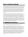
1. To put the Model 85 into the RECALL mode depress the MODE button repeatedly until rcl is
displayed on the screen along with the site ID number in the lower right corner. (see figure #1)
2. Depress the ENTER button to review the last set
of data that was saved. The Model 85 will display the
dissolved oxygen in % saturation and temperature.
Another press of the ENTER button will display the
dissolved oxygen in mg/L and the temperature.
rcl
Depress the ENTER button again and again to
review the conductivity, specific conductivity and
salinity readings. All of which are displayed with the
temperature.
01
figure #1
3. Depress the UP ARROW button to increment through the saved sets of data.
4. Depress the DOWN ARROW button to decrement through the saved sets of data.
5. When the correct site ID# is displayed, press the ENTER button to display the data.
YSI, Incorporated
Model 85
21
Saving Data
Section 8
6. When you have finished recalling data, press the MODE button to return to normal operation.
NOTE: The Model 85 will recall data as a list. When the UP ARROW is depressed the Model 85
will display the Site ID# for the previously recorded date. For example: If you are reviewing Site
ID# 5 and the UP ARROW is depressed the Model 85 will display Site ID# 4. If you are reviewing
Site ID# 5 and Site ID# 5 was the last set of data stored the DOWN ARROW button will display
Site ID# 1.
Here is an example of the Model 85 memory.
Site ID #1
Site ID #2
Site ID #3
If the UP ARROW button was pressed the Model 85 would display Site ID #2
Site ID #4
Site ID #5
8.3
ERASING STORED DATA
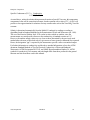
1. To erase the data that is stored into the Model 85’s memory, depress the MODE button repeatedly
until the Model 85 displays ErAS on the screen. (see figure #2)
2. Depress and hold the DOWN ARROW and
ENTER buttons simultaneously for approximately 5
seconds.
3. The Model 85 flashing DONE on the display for 1
to 2 seconds indicates successful erasure. The
instrument will automatically change to normal
operation after completion.
ErAS
IMPORTANT: Data in all 50 site ID’s will be
erased completely and will be lost forever. Do not
use the erase function until all recorded data has been
transcribed to an archive outside the Model 85.
figure #2
YSI, Incorporated
Model 85
22
SECTION 9 MAINTENANCE
9.1
CLEANING AND STORAGE
The single most important requirement for accurate and reproducible results in conductivity
measurement is a clean cell. A dirty cell will change the conductivity of a solution by contaminating
it.
NOTE: ALWAYS RINSE THE CONDUCTIVITY CELL WITH CLEAN WATER AFTER
EACH USE.
To clean the conductivity cell:
1. Dip the cell in cleaning solution and agitate for two to three minutes. Any one of the foaming
acid tile cleaners, such as Dow Chemical Bathroom Cleaner, will clean the cell adequately.
When a stronger cleaning preparation is required, use a solution of 1:1 isopropyl alcohol and 1
N HCl. Remove the cell from the cleaning solution.
2. Use the nylon brush (supplied) to dislodge any contaminants from inside the electrode chamber.
3. Repeat steps one and two until the cell is completely clean. Rinse the cell thoroughly in
deionized, or clean tap water.
4. Store the conductivity cell in the meter storage chamber.
NOTE: See Section 11, Dissolved Oxygen Probe Precautions for instructions on cleaning the
dissolved oxygen electrodes.
YSI, Incorporated
Model 85
23
Maintenance
YSI, Incorporated
Section 9
Model 85
24
SECTION 10 PRINCIPLES OF OPERATION
The dissolved oxygen sensor utilizes an oxygen permeable membrane that covers an electrolytic cell
consisting of a gold cathode and a porous silver anode. This membrane acts as a diffusion barrier
and an isolation barrier preventing fouling of the cathode surface by impurities in the environment.
Upon entering the cell through the membrane, oxygen is reduced at an applied potential of -0.8 V
referenced to the silver electrode. The reduction current at the cathode is directly proportional to the
partial pressure of oxygen in liquid (expressed as %-air saturation) which is proportional to the
concentration of dissolved oxygen (in mg/L) at a particular temperature. Thus the same partial
pressure of oxygen (% air-saturation) in liquid gives different concentrations of dissolved oxygen
(mg/L) at different temperatures because of the different solubility’s of oxygen at different
temperatures.
The conductivity cell utilizes four pure nickel electrodes for the measurement of solution
conductance. Two of the electrodes are current driven, and two are used to measure the voltage drop.
The measured voltage drop is then converted into a conductance value in milli-Siemens (millimhos).
To convert this value to a conductivity (specific conductance) value in milli-Siemens per cm
(mS/cm), the conductance is multiplied by the cell constant that has units of reciprocal cm (cm-1).
The cell constant for the Model 85 conductivity cell is 5.0/cm + 4%. For most applications, the cell
constant is automatically determined (or confirmed) with each deployment of the system when the
calibration procedure is followed. Solutions with conductivity’s of 1.00, 10.0, 50.0, and 100.0
mS/cm, which have been prepared in accordance with recommendation 56-1981 of the Organisation
Internationale de Métrologie Légale (OIML) are available from YSI. The instrument output is in
µS/cm or mS/cm for both conductivity and specific conductance. The multiplication of cell constant
times conductance is carried out automatically by the software.
10.1 TEMPERATURE EFFECT ON CONDUCTIVITY
The conductivity of solutions of ionic species is highly dependent on temperature, varying as much
as 3% for each change of one degree Celsius (temperature coefficient = 3%/C). In addition, the
temperature coefficient itself varies with the nature of the ionic species present.
Because the exact composition of a natural media is usually not known, it is best to report a
conductivity at a particular temperature, e.g. 20.2 mS/cm at 14 C. However, in many cases, it is also
useful to compensate for the temperature dependence in order to determine at a glance if gross
changes are occurring in the ionic content of the medium over time. For this reason, the Model 85
software also allows the user to output conductivity data in either raw or temperature compensated
form. If "Conductivity" is selected, values of conductivity that are NOT compensated for
temperature are output to the display. If "Specific Conductance" is selected, the Model 85 uses the
temperature and raw conductivity values associated with each determination to generate a specific
conductance value compensated to a user selected reference temperature (see Advanced Setup)
between 15 C and 25 C. Additionally the user can select any temperature coefficient from 0% to 4%
(see Advanced Setup). Using the Model 85 default reference temperature and temperature
coefficient (25 C and 1.91%), the calculation is carried out as in equation (1) below:
YSI, Incorporated
Model 85
25
Principles of Operation
Section 10
Specific Conductance (25°C) = Conductivity
1 + TC * (T - 25)
As noted above, unless the solution being measured consists of pure KCl in water, this temperature
compensated value will be somewhat inaccurate, but the equation with a value of TC = 0.0191 will
provide a close approximation for solutions of many common salts such as NaCl and NH4Cl and for
seawater.
Salinity is determined automatically from the Model 85 conductivity readings according to
algorithms found in Standard Methods for the Examination of Water and Wastewater (ed. 1989).
The use of the Practical Salinity Scale 1978 results in values which are unitless, since the
measurements are carried out in reference to the conductivity of standard seawater at 15 C.
However, the unitless salinity values are very close to those determined by the previously-used
method where the mass of dissolved salts in a given mass of water (parts per thousand) was reported.
Hence, the designation "ppt" is reported by the instrument to provide a more conventional output.
For further information on conductivity and the above standard information, refer to the ASTM
document, Standard Methods of Test for Electrical Conductivity of Water and Industrial
Wastewater, ASTM Designation D1125-82, and OIML Recommendation Number 56. ASTM
symbols for conductivity, cell constant, and path length differ from those preferred in the general
literature and also from those used in this manual.
YSI, Incorporated
Model 85
26
SECTION 11 DISCUSSION OF MEASUREMENT ERRORS
11.1 DISSOLVED OXYGEN MEASUREMENT ERRORS
There are three basic types of error. Type 1 errors are related to limitations of instrument design and
tolerances of instrument components. These are chiefly the meter linearity and the resistor
tolerances. Type 2 errors are due to basic probe accuracy tolerances, chiefly background signal,
probe linearity, and variations in membrane temperature coefficient. Type 3 errors are related to the
operator's ability to determine the conditions at the time of calibration. If calibration is performed
against more accurately known conditions, type 3 errors are appropriately reduced.
The sample calculations that follow are for a near extreme set of conditions.
TYPE 1 ERRORS
A. Meter linearity error: ±1% of full scale reading, or ±0.15 mg/l
B. Component and circuitry error: ±0.05 mg/l
TYPE 2 ERRORS
A. Temperature compensation for membrane temperature coefficient: ±0.03 mg/l
B. Temperature measurement errors: A maximum ±0.2oC probe error is equal to ±0.14 mg/l
YSI, Incorporated
Model 85
27
Discussion of Measurement Errors
Section 11
TYPE 3 ERRORS
A. Altitude:
A 1000-foot change in altitude is equal to an error of approximately 3% at the 10
mg/l level.
B. Humidity:
Errors occur if calibration is performed at less than 100% humidity. The error varies
with the temperature as follows:
TEMPERATURE
ERROR
0oC
0.02 mg/l
10oC
0.05 mg/l
20oC
0.12 mg/l
30oC
0.27 mg/l
40oC
0.68 mg/l
APPROXIMATING THE ERROR
It is unlikely that the actual error in any measurement will be the maximum possible error. A better
error approximation is obtained using a root mean squared (r.m.s.) calculation:
r.m.s. error = ±[1a2 + 1b2 + 2a2 + 2b2 + 3a2 + 3b2]½ mg/l
YSI, Incorporated
Model 85
28
Discussion of Measurement Errors
Section 11
11.2 CONDUCTIVITY MEASUREMENT ERRORS
System accuracy for conductivity measurements is equal to the sum of the errors contributed by the
environment and the various components of the measurement setup. These include:
•
•
•
•
•
•
Instrument accuracy
Cell-constant error
Solution temperature offset
Cell contamination (including air bubbles)
Electrical noise
Galvanic effects
Only the first three are of major concern for typical measurements, although the user should also be
careful to see that cells are clean and maintained in good condition at all times.
Instrument Accuracy = ± .5% maximum
The accuracy specified for the range being used is the worst case instrument error.
Cell-Constant Error = ± .5% maximum
Although YSI cells are warranted to be accurate to within one percent, you should still determine the
exact cell constant of your particular cell. Contamination or physical damage to the cell can alter the
cell constant. Performing a calibration will eliminate any error that might arise because of cell
constant change.
YSI cells are calibrated to within one percent of the stated cell constant at a single point. We
consider these products to be usefully linear over most instrument ranges. The cell constant can be
calibrated to ±0.35% accuracy with YSI conductivity calibrator solutions.
Temperature Error = ± 1% maximum
The solution temperature error is the product of the temperature coefficient and the temperature
offset from 25 C, expressed as a percentage of the reading that would have been obtained at 25 C.
The error is not necessarily a linear function of temperature. The statement of error is derived from a
25 C temperature offset and a 3%/ C temperature coefficient.
Total Error
Considering only the above three factors, system accuracy under worst case conditions will be ±2%,
although the actual error will be considerably less if recommended and properly calibrated cells and
instrument ranges are used. Additional errors, which can essentially be eliminated with proper
handling, are described below.
Cell Contamination
This error is usually due to contamination of the solution being measured, which occurs when
solution is carried-over from the last solution measured. Thus, the instrument might be correctly
reporting the conductivity seen, but the reading does not accurately represent the value of the bulk
YSI, Incorporated
Model 85
29
Discussion of Measurement Errors
Section 11
solution. Errors will be most serious when low conductivity solutions are contaminated by carryover from high conductivity solutions, and can then be of an order of magnitude or more.
Follow the cleaning instructions carefully before attempting low conductivity measurements with a
cell of unknown history or one that has been previously used in higher value solutions.
An entirely different form of contamination sometimes occurs due to a buildup of foreign material
directly on cell electrodes. While rare, such deposits have, on occasion, markedly reduced the
effectiveness of the electrodes. The result is an erroneously low conductance reading.
Electrical-Noise Errors
Electrical noise can be a problem in any measurement range, but will contribute the most error and
be the most difficult to eliminate when operating in the lowest ranges. The noise may be either lineconducted or radiated or both, and may require, grounding, shielding, or both.
Galvanic and Miscellaneous Effects
In addition to the error sources described above, there is another class of contributors that can be
ignored for all but the most meticulous of laboratory measurements. These errors are always small
and are generally completely masked by the error budget for cell-constant calibration, instrument
accuracy, etc. Examples range from parasitic reactance associated with the solution container and its
proximity to external objects to the minor galvanic effects resulting from oxide formation or
deposition on electrodes. Only trial and error in the actual measurement environment can be
suggested as an approach to reduce such errors. If the reading does not change as the setup is
adjusted, errors due to such factors can be considered too small to see.
YSI, Incorporated
Model 85
30
Discussion of Measurement Errors
Section 11
11.3 DISSOLVED OXYGEN PROBE PRECAUTIONS
1. Membrane life depends on usage. Membranes will last a long time if installed properly and
treated with care. Erratic readings are a result of loose, wrinkled, damaged, or fouled
membranes, or from large (more than 1/8" diameter) bubbles in the electrolyte reservoir. If
erratic readings or evidence of membrane damage occurs, you should replace the membrane and
the KCl solution. The average replacement interval is two to four weeks.
2. If the membrane is coated with oxygen consuming (e.g. bacteria) or oxygen evolving organisms
(e.g. algae), erroneous readings may occur.
3. Chlorine, sulfur dioxide, nitric oxide, and nitrous oxide can affect readings by behaving like
oxygen at the probe. If you suspect erroneous readings, it may be necessary to determine if these
gases are the cause.
4. Avoid any environment that contains substances that may attack the probe materials. Some of
these substances are concentrated acids, caustics, and strong solvents. The probe materials that
come in contact with the sample include FEP Teflon, stainless steel, epoxy, polyetherimide and
the polyurethane cable covering.
5. For correct probe operation, the gold cathode must always be bright. If it is tarnished (which can
result from contact with certain gases) or plated with silver, the gold surface must be restored. To
restore the cathode, you may either return the instrument to the factory or clean it using the YSI
5238 probe reconditioning kit. Never use chemicals or abrasives not supplied with this kit.
NOTE: Model 85 probes built before July, 1996 (serial numbers starting with 96F or lower),
should be cleaned with the sanding disc mounted on a FLAT surface. Do NOT use the
curved tool provided in the 5238 probe reconditioning kit on these probes.
6. It is also possible for the silver anode to become contaminated, which will prevent successful
calibration. To clean the anode, remove the membrane and soak the probe overnight in 3%
ammonium hydroxide. Next, rinse the sensor tip with deionized water, add new KCl solution,
and install a new membrane. Turn the instrument on and allow the system to stabilize for at least
30 minutes. If, after several hours, you are still unable to calibrate, return the YSI Model 85
system to an authorized service center for service.
7. To keep the electrolyte from drying out, store the probe in the calibration chamber with the small
piece of sponge.
YSI, Incorporated
Model 85
31
Discussion of Measurement Errors
YSI, Incorporated
Section 11
Model 85
32
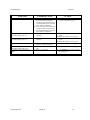
SECTION 12 TROUBLESHOOTING
SYMPTOM
POSSIBLE CAUSE
ACTION
1. Instrument will not turn on
A. Low battery voltage
B. Batteries installed wrong
C. Meter requires service
A. Replace batteries
B. Check battery polarity.
C. Return system for service
2. Instrument will not calibrate
(Dissolved Oxygen)
A. Membrane is fouled or damaged
B. Probe anode is fouled or dark
C. Probe cathode is tarnished
D. System requires service
A. Replace membrane & KCl
B. Clean anode
C. Clean cathode
D. Return system for service
3. Instrument will not calibrate
(Conductivity)
A. Cell is contaminated
A. See “Maintenance” Section
4. Instrument "locks up"
A. Instrument has rec'd a shock
B. Batteries are low or damaged
C. System requires service
A & B. Remove battery lid, wait 15
seconds for reset, replace lid.
C. Return system for service
5. Instrument readings are inaccurate
(Dissolved Oxygen)
A. Cal altitude is incorrect
B. Probe not in 100% O2 saturated air
during Cal procedure
C. Membrane fouled or damaged
D. Probe anode is fouled or dark
E. Probe cathode is tarnished
F. System requires service
A. Recalibrate w/correct value
B. Moisten sponge & place in Cal chamber
w/ probe & Recal
C. Replace membrane
D. Clean anode
E. Clean cathode
F. Return system for service
6. Instrument readings are inaccurate
(Conductivity)
A. Calibration is required
B. Cell is contaminated
C. Tempco is set incorrectly
D. Reference temperature incorrect
E. Readings are or are not temperature
compensated.
A. See “Calibration” Section
B. See “Maintenance” Section
C. See “Advanced Setup” Section
D. See “Advanced Setup” Section
E. See “Making Measurements”
Section
7..LCD displays "LO BAT"
A. Batteries are low or damaged
A. Replace batteries
A. Conductivity reading is >200 mS
B. Temperature reading is >65°C
C. Temperature reading is <-5°C
D. Salinity reading is >80 ppt
E. User cell constant cal K is >5.25
F. DO temperature is >46°C
G. DO % saturation is >200%
H. DO concentration is >20 mg/L
A. User cell constant cal K is <4.9
B. DO current too low to calibrate
In all cases, check calibration values and
procedures; check advanced setup settings.
Main display flashes “off”
8. Main Display reads “OVEr”
(Secondary display reads “ovr”)
(Secondary display reads “udr”)
9. Main display reads “Undr”
10. Main display reads “rErr”
A. Reading exceeds user selected
manual range.
11. Main display reads “PErr”
A. User cell constant cal K is 0.0
B. Incorrect sequence of keystrokes.
If each of these are set correctly,
return instrument for service.
A.
Recalibrate instrument using known
good conductivity standard.
Follow cell cleaning procedure in
the Maintenance section.
B. Replace membrane, clean probe
A. Use the mode key to select a higher or
lower manual range, or set system to
autoranging.
A. See “Advanced Setup” section.
B. Refer to manual section for step by step
instruction for the function you are
attempting.
YSI, Incorporated
Model 85
33
Troubleshooting
SYMPTOM
12. Main display reads “LErr”
Section 12
POSSIBLE CAUSE
13. Main display reads “Err”
(Secondary display reads “ra”)
A. In temperature compensated
conductivity mode, temperature
exceeds the values computed using
user defined temperature coefficient
and/or reference temperature.
B. In cell constant cal mode, temperature
exceeds the values computed using
user defined temperature coefficient
and/or reference temperature.
A. System has failed its RAM test check
procedure.
14. Main display reads “Err”
(Secondary display reads “ro”)
A. System has failed its ROM test check
procedure.
15. Secondary display reads “rEr”
A. Temperature jumper is set to °F and
reading is >199.9°F but <203°F.
A. EEPROM has failed to respond in
time.
A. Meter is in recall mode.
16. Main display reads “FAIL”
(Secondary display reads “eep”)
17. Readings on main display don’t
change
YSI, Incorporated
Model 85
ACTION
A. & B. Adjust user defined tempco or
reference temperature. (pg. 10)
A. Turn instrument OFF and back ON
again.
B. Return the system for service (pg. 26)
A. Turn instrument OFF and back ON
again.
B. Return the system for service (pg. 26)
A. Return the system for service. (pg. 26)
A. Return the system for service. (pg. 26)
A. Press MODE button to return to Normal
Operation (pg. 12)
34
SECTION 13 WARRANTY AND REPAIR
YSI Model 85 Handheld Meters are warranted for two years from date of purchase by the end user against
defects in materials and workmanship. YSI Model 85 probes and cables are warranted for one year from date
of purchase by the end user against defects in material and workmanship. Within the warranty period, YSI
will repair or replace, at its sole discretion, free of charge, any product that YSI determines to be covered by
this warranty.
To exercise this warranty, write or call your local YSI representative, or contact YSI Customer Service in
Yellow Springs, Ohio. Send the product and proof of purchase, transportation prepaid, to the Authorized
Service Center selected by YSI. Repair or replacement will be made and the product returned, transportation
prepaid. Repaired or replaced products are warranted for the balance of the original warranty period, or at least
90 days from date of repair or replacement.
Limitation of Warranty
This Warranty does not apply to any YSI product damage or failure caused by (i) failure to install, operate or
use the product in accordance with YSI’s written instructions, (ii) abuse or misuse of the product, (iii) failure
to maintain the product in accordance with YSI’s written instructions or standard industry procedure, (iv) any
improper repairs to the product, (v) use by you of defective or improper components or parts in servicing or
repairing the product, or (vi) modification of the product in any way not expressly authorized by YSI.
THIS WARRANTY IS IN LIEU OF ALL OTHER WARRANTIES, EXPRESSED OR IMPLIED, INCLUDING ANY
WARRANTY OF MERCHANTABILITY OR FITNESS FOR A PARTICULAR PURPOSE. YSI’s LIABILITY
UNDER THIS WARRANTY IS LIMITED TO REPAIR OR REPLACEMENT OF THE PRODUCT, AND THIS
SHALL BE YOUR SOLE AND EXCLUSIVE REMEDY FOR ANY DEFECTIVE PRODUCT COVERED BY THIS
WARRANTY. IN NO EVENT SHALL YSI BE LIABLE FOR ANY SPECIAL, INDIRECT, INCIDENTAL OR
CONSEQUENTIAL DAMAGES RESULTING FROM ANY DEFECTIVE PRODUCT COVERED BY THIS
WARRANTY.
YSI, Incorporated
Model 85
35
Warranty and Repair
Section 13
AUTHORIZED U.S. SERVICE CENTERS
Please visit www.ysi.com or contact YSI Technical Support for the nearest authorized service center.
YSI Incorporated • Technical Support • Phone: +1 937 767-7241 • 800 897-4151 • Fax: 937 767-1058 • Email: [email protected]
YSI, Incorporated
Model 85
36
Warranty and Repair
Section 13
CLEANING INSTRUCTIONS
NOTE: Before they can be serviced, equipment exposed to biological, radioactive, or toxic
materials must be cleaned and disinfected. Biological contamination is presumed for any
instrument, probe, or other device that has been used with body fluids or tissues, or with
wastewater. Radioactive contamination is presumed for any instrument, probe or other device
that has been used near any radioactive source.
If an instrument, probe, or other part is returned or presented for service without a Cleaning
Certificate, and if in our opinion it represents a potential biological or radioactive hazard, our
service personnel reserve the right to withhold service until appropriate cleaning,
decontamination, and certification has been completed. We will contact the sender for
instructions as to the disposition of the equipment. Disposition costs will be the responsibility of
the sender.
When service is required, either at the user's facility or at YSI, the following steps must be taken
to insure the safety of our service personnel.
1. In a manner appropriate to each device, decontaminate all exposed surfaces, including any
containers. 70% isopropyl alcohol or a solution of 1/4 cup bleach to 1-gallon tap water are
suitable for most disinfecting. Instruments used with wastewater may be disinfected with .5%
Lysol if this is more convenient to the user.
2. The user shall take normal precautions to prevent radioactive contamination and must use
appropriate decontamination procedures should exposure occur.
3. If exposure has occurred, the customer must certify that decontamination has been
accomplished and that no radioactivity is detectable by survey equipment.
4. Any product being returned to the YSI Repair Center, should be packed securely to prevent
damage.
5. Cleaning must be completed and certified on any product before returning it to YSI.
YSI, Incorporated
Model 85
37
Warranty and Repair
Section 13
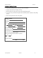
PACKING INSTRUCTIONS
1. Clean and decontaminate items to insure the safety of the handler.
2. Complete and include the Cleaning Certificate.
3. Place the product in a plastic bag to keep out dirt and packing material.
4. Use a large carton, preferably the original, and surround the product completely with packing
material.
5. Insure for the replacement value of the product.
Cleaning Certificate
Organization
Department
Address
City
State
Country
Zip
Phone
Model No. of Device
Lot Number
Contaminant (if known)
Cleaning Agent(s) used
Radioactive Decontamination Certified?
(Answer only if there has been radioactive exposure)
Yes
No
Cleaning Certified By
Name
YSI, Incorporated
Date
Model 85
38
Warranty and Repair
YSI, Incorporated
Section 13
Model 85
39
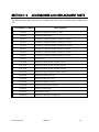
SECTION 14
ACCESSORIES AND REPLACEMENT PARTS
The following parts and accessories are available from YSI or any Franchise Dealer authorized by
YSI.
YSI ORDER NUMBER
DESCRIPTION
YSI 5906
Replacement Membrane Cap Kit ( 6 each )
YSI 5238
Probe Reconditioning Kit
YSI 3161
Conductivity Calibration Solution 1,000 µ/cm (1 Quart)
YSI 3163
Conductivity Calibration Solution 10,000 µ/cm (1 Quart)
YSI 3165
Conductivity Calibration Solution 100,000 µ/cm (1 Quart)
YSI 3167
Conductivity Calibration Solution 1,000 µ/cm (8 pints)
YSI 3168
Conductivity Calibration Solution 10,000 µ/cm (8 pints)
YSI 3169
Conductivity Calibration Solution 50,000 µ/cm (8 pints)
YSI 5520
Carrying Case
YSI 118510
Replacement Probe & Cable Assembly (10 feet)
YSI 118522
Replacement Probe & Cable Assembly (25 feet)
YSI 118527
Replacement Probe & Cable Assembly (50 feet)
YSI 118519
Replacement Probe and Cable Assembly (100 feet)
YSI 038501
Replacement Front Case Cover
YSI 055242
Replacement Rear Case Cover
YSI 055244
Replacement Battery Cover Kit
YSI 055204
Replacement Case Gasket and Screw
YSI 055219
Storage Chamber Sponge
YSI 030156
Main Board Assembly
YSI 038213
Replacement Electrode Cleaning Brush
YSI, Incorporated
Model 85
40
Accessories and Replacements
YSI, Incorporated
Section 14
Model 85
41
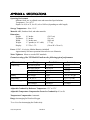
APPENDIX A SPECIFICATIONS
Operating Environment
Medium: fresh, sea, or polluted water and most other liquid solutions.
Temperature: -5 to +65 °C
Depth: 0 to 10, 0 to 25, 0 to 50, or 0 to 100 feet (depending on cable length)
Storage Temperature: -10 to +50 °C
Material: ABS, Stainless Steel, and other materials
Dimensions:
Height:
Thickness:
Width:
Weight:
Display:
9.5 inches
2.2 inches
3.5 inches max.
1.7 pounds (w/ 10’ cable)
2.3”W x 1.5”L
(24.13 cm)
(5.6 cm)
(8.89 cm)
(.77 kg)
(5.8cm W x 3.8cm L)
Power: 9 VDC -6 AA-size Alkaline Batteries (included)
Approximately 100 hours operation from each new set of batteries
Water Tightness: Meets or exceeds IP65 standards
Extensive testing of the YSI Model 85 indicates the following typical performance:
Measurement
Conductivity
Salinity
Temperature
Dissolved Oxygen
Range
Resolution
0 to 499.9 µS/cm
0 to 4999 µS/cm
0 to 49.99 mS/cm
0 to 200.0 mS/cm
0 to 80 ppt
-5 to +65 °C
0 to 200 % Air Sat.
0 to 20 mg/L
0.1 µS/cm
1.0 µS/cm
.01 mS/cm
0.1 mS/cm
.1 ppt
0.1 °C
0.1% Air Saturation
0.01 mg/L
Accuracy
± .5% FS
± .5% FS
± .5% FS
± .5% FS
± 2%, or ± 0.1 ppt
± 0.1 °C (±1 lsd)
± 2% Air Saturation
± 0.3 mg/L
Adjustable Conductivity Reference Temperature: 15°C to 25°C
Adjustable Temperature Compensation Factor for Conductivity: 0% to 4%
Temperature Compensation: Automatic
Range: Autoranging for Dissolved Oxygen
User selected or Autoranging for Conductivity
YSI, Incorporated
Model 85
42
Specifications
YSI, Incorporated
Appendix A
Model 85
43
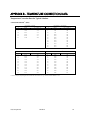
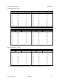
APPENDIX B - TEMPERATURE CORRECTION DATA
Temperature Correction Data for Typical Solutions
A. Potassium Chloride** (KCl)
Concentration: 1 x 10⁻¹ mole/liter
Concentration: 1 mole/liter
C
mS/cm
%/ C (to 25 C)
0
5
10
15
20
25
65.10
73.89
82.97
92.33
101.97
111.90
1.67
1.70
1.72
1.75
1.77
1.80
C
mS/cm
%/ C (to 25 C)
0
5
10
15
20
25
30
35
37.5
40
45
50
7.13
8.22
9.34
10.48
11.65
12.86
14.10
15.38
16.04
16.70
18.05
19.43
1.78
1.80
1.83
1.85
1.88
1.90
1.93
1.96
1.98
1.99
2.02
2.04
Concentration: 1 x 10⁻² mole/liter
Concentration: 1 x 10⁻³ mole/liter
C
mS/cm
%/ C (to 25 C)
0
5
10
15
20
25
30
35
37.5
40
45
50
0.773
0.892
1.015
1.143
1.275
1.412
1.553
1.697
1.771
1.845
1.997
2.151
1.81
1.84
1.87
1.90
1.93
1.96
1.99
2.02
2.03
2.05
2.07
2.09
C
mS/cm
%/ C (to 25 C)
0
5
10
15
20
25
30
35
37.5
40
45
50
0.080
0.092
0.105
0.119
0.133
0.147
0.162
0.178
0.186
0.194
0.210
0.226
1.84
1.88
1.92
1.96
1.99
2.02
2.05
2.07
2.08
2.09
2.11
2.13
** Charts developed by interpolating data from International Critical Tables, Vol. 6, pp. 229-253, McGraw-Hill Book Co., NY.
YSI, Incorporated
Model 85
44
Temperature Correction Data
Appendix B
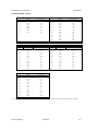
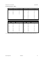
B. Sodium Chloride* (NaCl)
Saturated solutions at all temperatures
Concentration: 0.5 mole/liter
C
mS/cm
%/ C (to 25 C)
0
5
10
15
20
25
30
134.50
155.55
177.90
201.40
225.92
251.30
277.40
1.86
1.91
1.95
1.99
2.02
2.05
2.08
C
mS/cm
%/ C (to 25 C)
0
5
10
15
20
25
30
35
37.5
40
45
50
25.90
29.64
33.61
37.79
42.14
46.65
51.28
56.01
58.40
60.81
65.65
70.50
1.78
1.82
1.86
1.90
1.93
1.96
1.99
2.01
2.02
2.02
2.04
2.05
Concentration: 1 x 10⁻¹ mole/liter
Concentration: 1 x 10⁻² mole/liter
C
mS/cm
%/ C (to 25 C)
0
5
10
15
20
25
30
35
37.5
40
45
50
5.77
6.65
7.58
8.57
9.60
10.66
11.75
12.86
13.42
13.99
15.14
16.30
1.83
1.88
1.92
1.96
1.99
2.02
2.04
2.06
2.07
2.08
2.10
2.12
C
mS/cm
%/ C (to 25 C)
0
5
10
15
20
25
30
35
37.5
40
45
50
0.632
0.731
0.836
0.948
1.064
1.186
1.312
1.442
1.508
1.575
1.711
1.850
1.87
1.92
1.97
2.01
2.05
2.09
2.12
2.16
2.17
2.19
2.21
2.24
Concentration: 1 x 10⁻³ mole/liter
C
mS/cm
%/ C (to 25 C)
0
5
10
15
20
25
30
35
37.5
40
45
50
0.066
0.076
0.087
0.099
0.111
0.124
0.137
0.151
0.158
0.165
0.180
0.195
1.88
1.93
1.98
2.02
2.07
2.11
2.15
2.19
2.20
2.22
2.25
2.29
* Charts developed by interpolating data from the CRC Handbook of Chemistry and Physics, 42nd ed., p. 2606, The Chemical Rubber Company, Cleveland.
YSI, Incorporated
Model 85
45
Temperature Correction Data
Appendix B
C. Lithium Chloride* (LiCl)
Concentration: 1 x 10⁻¹ mole/liter
Concentration: 1 mole/liter
C
mS/cm
%/ C (to 25 C)
0
5
10
15
20
25
30
35
37.5
40
45
50
39.85
46.01
52.42
59.07
65.97
73.10
80.47
88.08
91.97
95.92
103.99
112.30
1.82
1.85
1.89
1.92
1.95
1.98
2.02
2.05
2.07
2.08
2.11
2.15
C
mS/cm
%/ C (to 25 C)
0
5
10
15
20
25
30
35
37.5
40
45
50
5.07
5.98
6.87
7.75
8.62
9.50
10.40
11.31
11.78
12.26
13.26
14.30
1.87
1.85
1.85
1.85
1.85
1.86
1.88
1.91
1.92
1.94
1.98
2.02
Concentration: 1 x 10⁻² mole/liter
Concentration: 1 x 10⁻³ mole/liter
C
mS/cm
%/ C (to 25 C)
0
5
10
15
20
25
30
35
37.5
40
45
50
0.567
0.659
0.755
0.856
0.961
1.070
1.183
1.301
1.362
1.423
1.549
1.680
1.88
1.92
1.96
2.00
2.04
2.08
2.12
2.16
2.18
2.20
2.24
2.28
C
mS/cm
%/ C (to 25 C)
0
5
10
15
20
25
30
35
37.5
40
45
50
0.059
0.068
0.078
0.089
0.101
0.114
0.127
0.140
0.147
0.154
0.166
0.178
1.93
2.03
2.12
2.19
2.25
2.28
2.31
2.32
2.32
2.31
2.29
2.25
D. Potassium Nitrate** (KNO3)
Concentration: 1 x 10⁻¹ mole/liter
Concentration: 1 x 10⁻² mole/liter
C
mS/cm
%/ C (to 25 C)
0
5
10
15
20
25
30
35
37.5
40
45
50
6.68
7.71
8.75
9.81
10.90
12.01
13.15
14.32
14.92
15.52
16.75
18.00
1.78
1.79
1.81
1.83
1.85
1.87
1.90
1.92
1.94
1.95
1.97
2.00
C
mS/cm
%/ C (to 25 C)
0
5
10
15
20
25
30
35
37.5
40
45
50
0.756
0.868
0.984
1.105
1.229
1.357
1.488
1.622
1.690
1.759
1.898
2.040
1.77
1.80
1.83
1.86
1.88
1.90
1.93
1.95
1.96
1.97
1.99
2.01
* Charts developed by interpolating data from the CRC Handbook of Chemistry and Physics, 42nd ed., p. 2606, The Chemical Rubber Company, Cleveland.
** Charts developed by interpolating data from International Critical Tables, Vol. 6, pp. 229-253, McGraw-Hill Book Co., NY.
YSI, Incorporated
Model 85
46
Temperature Correction Data
Appendix B
E. Ammonium Chloride* (NH4Cl)
Concentration: 1 x 10⁻¹ mole/liter
Concentration: 1 mole/liter
C
mS/cm
%/ C (to 25 C)
0
5
10
15
20
25
64.10
74.36
83.77
92.35
100.10
107.00
1.60
1.53
1.45
1.37
1.29
1.21
C
mS/cm
%/ C (to 25 C)
0
5
10
15
20
25
30
35
37.5
40
45
50
6.96
7.98
9.09
10.27
11.50
12.78
14.09
15.43
16.10
16.78
18.12
19.45
1.82
1.88
1.93
1.97
2.00
2.03
2.06
2.07
2.08
2.08
2.09
2.09
Concentration: 1 x 10⁻² mole/liter
Concentration: 1 x 10⁻³ mole/liter
C
mS/cm
%/ C (to 25 C)
0
5
10
15
20
25
30
35
37.5
40
45
50
0.764
0.889
1.015
1.144
1.277
1.414
1.557
1.706
1.782
1.860
2.020
2.186
1.84
1.86
1.88
1.91
1.94
1.97
2.02
2.06
2.08
2.10
2.14
2.18
C
mS/cm
%/ C (to 25 C)
0
5
10
15
20
25
30
35
37.5
40
45
50
0.078
0.092
0.105
0.119
0.133
0.148
0.162
0.178
0.186
0.194
0.210
0.227
1.88
1.90
1.91
1.93
1.95
1.98
2.01
2.04
2.06
2.07
2.11
2.15
* Charts developed by interpolating data from the CRC Handbook of Chemistry and Physics, 42nd ed., p. 2606, The Chemical Rubber Company, Cleveland.
YSI, Incorporated
Model 85
47
APPENDIX C REQUIRED NOTICE
The Federal Communications Commission defines this product as a computing device and requires
the following notice:
This equipment generates and uses radio frequency energy and if not installed and used properly,
may cause interference to radio and television reception. There is no guarantee that interference will
not occur in a particular installation. If this equipment does cause interference to radio or television
reception, which can be determined by turning the equipment off and on, the user is encouraged to
try to correct the interference by one or more of the following measures:
•
•
•
•
re-orient the receiving antenna
relocate the computer with respect to the receiver
move the computer away from the receiver
plug the computer into a different outlet so that the computer and receiver are on
different branch circuits.
If necessary, the user should consult the dealer or an experienced radio/television technician for
additional suggestions. The user may find the following booklet, prepared by the Federal
Communications Commission, helpful: "How to Identify and Resolve Radio-TV Interference
Problems." This booklet is available from the U.S. Government Printing Office, Washington, D.C.
20402, Stock No. 0004-000-00345-4.
YSI, Incorporated
Model 85
48
Required Notice
YSI, Incorporated
Appendix C
Model 85
49
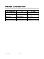
APPENDIX D CONVERSION CHART
TO CONVERT FROM
TO
EQUATION
Feet
Meters
Multiply by 0.3048
Meters
Feet
Multiply by 3.2808399
Degrees Celsius
Degrees Fahrenheit
(9/5
Degrees Fahrenheit
Degrees Celsius
5/9 (oF-32)
Milligrams per liter (mg/l)
Parts per million (ppm)
Multiply by 1
YSI, Incorporated
Model 85
o
C)+32
50
Conversion Chart
YSI, Incorporated
Appendix D
Model 85
51
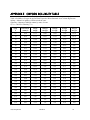
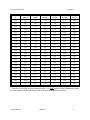
APPENDIX E OXYGEN SOLUBILITY TABLE
Table A: Solubility of Oxygen in mg/l in Water Exposed to Water-Saturated Air at 760 mm Hg Pressure.
Salinity = Measure of quantity of dissolved salts in water.
Chlorinity = Measure of chloride content, by mass, of water.
S(0/00) = 1.80655 x Chlorinity (0/00)
Temp
o
C
Chlorinity:0
Salinity:0
5.0 ppt
9.0 ppt
10.0 ppt
18.1 ppt
15.0 ppt
27.1 ppt
20.0 ppt
36.1 ppt
25.0 ppt
45.2 ppt
0.0
14.62
13.73
12.89
12.10
11.36
10.66
1.0
14.22
13.36
12.55
11.78
11.07
10.39
2.0
13.83
13.00
12.22
11.48
10.79
10.14
3.0
13.46
12.66
11.91
11.20
10.53
9.90
4.0
13.11
12.34
11.61
10.92
10.27
9.66
5.0
12.77
12.02
11.32
10.66
10.03
9.44
6.0
12.45
11.73
11.05
10.40
9.80
9.23
7.0
12.14
11.44
10.78
10.16
9.58
9.02
8.0
11.84
11.17
10.53
9.93
9.36
8.83
9.0
11.56
10.91
10.29
9.71
9.16
8.64
10.0
11.29
10.66
10.06
9.49
8.96
8.45
11.0
11.03
10.42
9.84
9.29
8.77
8.28
12.0
10.78
10.18
9.62
9.09
8.59
8.11
13.0
10.54
9.96
9.42
8.90
8.41
7.95
14.0
10.31
9.75
9.22
8.72
8.24
7.79
15.0
10.08
9.54
9.03
8.54
8.08
7.64
16.0
9.87
9.34
8.84
8.37
7.92
7.50
17.0
9.67
9.15
8.67
8.21
7.77
7.36
18.0
9.47
8.97
8.50
8.05
7.62
7.22
19.0
9.28
8.79
8.33
7.90
7.48
7.09
20.0
9.09
8.62
8.17
7.75
7.35
6.96
21.0
8.92
8.46
8.02
7.61
7.21
6.84
22.0
8.74
8.30
7.87
7.47
7.09
6.72
23.0
8.58
8.14
7.73
7.34
6.96
6.61
YSI, Incorporated
Model 85
52
Oxygen Solubility Table
Appendix E
Temp
o
C
Chlorinity:0
Salinity:0
5.0 ppt
9.0 ppt
10.0 ppt
18.1 ppt
15.0 ppt
27.1 ppt
20.0 ppt
36.1 ppt
25.0 ppt
45.2 ppt
24.0
8.42
7.99
7.59
7.21
6.84
6.50
25.0
8.26
7.85
7.46
7.08
6.72
6.39
26.0
8.11
7.71
7.33
6.96
6.62
6.28
27.0
7.97
7.58
7.20
6.85
6.51
6.18
28.0
7.83
7.44
7.08
6.73
6.40
6.09
29.0
7.69
7.32
6.96
6.62
6.30
5.99
30.0
7.56
7.19
6.85
6.51
6.20
5.90
31.0
7.43
7.07
6.73
6.41
6.10
5.81
32.0
7.31
6.96
6.62
6.31
6.01
5.72
33.0
7.18
6.84
6.52
6.21
5.91
5.63
34.0
7.07
6.73
6.42
6.11
5.82
5.55
35.0
6.95
6.62
6.31
6.02
5.73
5.46
36.0
6.84
3.52
6.22
5.93
5.65
5.38
37.0
6.73
6.42
6.12
5.84
5.56
5.31
38.0
6.62
6.32
6.03
5.75
5.48
5.23
39.0
6.52
6.22
5.98
5.66
5.40
5.15
40.0
6.41
6.12
5.84
5.58
5.32
5.08
41.0
6.31
6.03
5.75
5.49
5.24
5.01
42.0
6.21
5.93
5.67
5.41
5.17
4.93
43.0
6.12
5.84
5.58
5.33
5.09
4.86
44.0
6.02
5.75
5.50
5.25
5.02
4.79
45.0
5.93
5.67
5.41
5.17
4.94
4.72
* This table is provided for your information only. It is NOT required when calibrating the Model
85 in accordance with the instructions outlined in the section entitled Calibration.
YSI, Incorporated
Model 85
53
APPENDIX F CALIBRATION VALUES TABLE
Table A: Calibration values for various atmospheric pressures and altitudes.
Note: This table is for your information only. It is not required for calibration.
Pressure
Inches of Hg
30.23
29.92
29.61
29.33
29.02
28.74
28.43
28.11
27.83
27.52
27.24
26.93
26.61
26.34
26.02
25.75
25.43
25.12
24.84
24.53
24.25
23.94
23.62
23.35
23.03
22.76
22.44
22.13
21.85
21.54
21.26
20.94
20.63
20.35
YSI, Incorporated
Pressure
mm Hg
768
760
752
745
737
730
722
714
707
699
692
684
676
669
661
654
646
638
631
623
616
608
600
593
585
578
570
562
555
547
540
532
524
517
Pressure
kPA
102.3
101.3
100.3
99.3
98.3
97.3
96.3
95.2
94.2
93.2
92.2
91.2
90.2
89.2
88.2
87.1
86.1
85.1
84.1
83.1
82.1
81.1
80.0
79.0
78.0
77.0
76.0
75.0
74.0
73.0
71.9
70.9
69.9
68.9
Model 85
Altitude
in feet
-276
0
278
558
841
1126
1413
1703
1995
2290
2587
2887
3190
3496
3804
4115
4430
4747
5067
5391
5717
6047
6381
6717
7058
7401
7749
8100
8455
8815
9178
9545
9917
10293
Altitude
in meters
-84
0
85
170
256
343
431
519
608
698
789
880
972
1066
1160
1254
1350
1447
1544
1643
1743
1843
1945
2047
2151
2256
2362
2469
2577
2687
2797
2909
3023
3137
Calibration
Value in %
101
100
99
98
97
96
95
94
93
92
91
90
89
88
87
86
85
84
83
82
81
80
79
78
77
76
75
74
73
72
71
70
69
68
54
Calibration Values Table
YSI, Incorporated
Appendix F
Model 85
55
1700/1725 Brannum Lane
Yellow Springs, Ohio 45387
+1 937 767-7241
800 765-4974 (US)
FAX (937) 767-9353
E-mail: [email protected]
Website: www.YSI.com
ITEM # 038503
DRW # A38503 - Web
Revision E - Web
November 1998