1
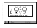
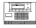
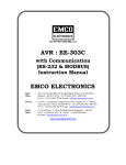
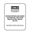
(ISO 9001:2000 COMPANY)
Parallel Control Unit
EE-501
INSTRUCTION MANUAL
Instruction Manual
for
Parallel Control Unit
Type EE-501
EMCO ELECTRONICS
Works : Unit No. 13, "Kedarnath", Tungareshwar Industrial Complex No. 1, Village Sativali,
Vasai(E), Dist : Thane - 401208. Tel.:(0250)2481783 / 1804, Fax : (0250)2481087,
Email : [email protected]
Office : 302, Vasan Udyog Bhavan, Sanapati Bapat Marg, Opp. Phoenix mill / Big Bazar,
Lower Parel(W), Mumbai - 400 013. Tel.:(022)24902283/24923183,
Fax : +91-022-24951024, E-mail : [email protected]
South : 15, Wood Street, (1st Floor),Richmond Road, Bangalore - 560 025
Office Tel : (080) 557 0215
Fax : +91-80-556 6606
E-mail : [email protected]
DOC No. : MK 07 - 702 / ISS. 1
CONTENTS
Sr. No.
TITLE
PAGE No.
I
GENERAL DESCRIPTION
1
II
TECHNICAL SPECIFICATIONS
1
III
FRONT PANEL INDICATIONS / CONTROLS
2
IV
OPERATING PROCEDURE
4
V
LIST OF DRAWINGS
5
VI
WARRANTY
6
I GENERAL DESCRIPTION
The Parallel Control Unit (PCU) is used for controlling 2 Transformers in parallel. The
transformers have to be identical i.e. with the same number of taps.
“Raise” & “Lower” NO contacts from AVR1 & AVR2 are connected to the PCU, & the outputs
from the PCU are connected to the OLTC1 & OLTC2 respectively.
Switches on the front panel of PCU allows for selecting AVR1 or AVR2 as master & the other
as the follower, or both AVRs as independent (masters).
Tap Position of both the Transformers are displayed on the PCU. When the master AVR
gives either Raise / Lower Pulse to the transformer, the tap numbers are compared after
some delay & if there is a difference in the tap nunbers the Raise / Lower pulse is given to the
follower.
Incase the tap position of the 2 transformers in parallel are unequal for 5 minutes, out of step
indication is given & both OLTCs are blocked.
External A/M Switch (NO contacts) are sensed for determining Auto / Manual mode of
operation. When manual mode is selected, the PCU is blocked i.e. no output pulses are
given to the OLTCs. The PCU is also blocked when both the AVRs are set in follower mode.
II TECHNICAL SPECIFICATIONS
Auxiliary Supply
:
110V/230V AC, 50Hz, ±15%, 15VA
Maximum Tap No. of
Transformers
:
21 (to be specified in PO &
should be the same for both transformers)
Time Delay between Master
& Follower Pulse
:
Settable between 10 to 150 secs
Mode of Operation
:
Selected through Front Panel Switches
¯ ¯ - Independent AVRs
¯ - - AVR1 (Master), AVR2(Follower)
- ¯ - AVR1 (Follower), AVR2(Master)
- - - PCU blocked
Overall Size
:
92mm X 192mm X 220mm (H X W X D)
Panel Cutout
:
90mm X 184mm(H X W)
1
Inputs
Auto / Manual
:
External (NO) potential free contacts
Raise & Lower Input Pulses
:
(NO) potential free contacts from AVR1 & AVR2.
Tap Position Indicators
:
3 wires from Resistor Chain (Max, Wiper, Min)
with 1KW / step from both OLTCs
Bus Coupler Input
:
(NO) potential free contacts from Bus Coupler
Raise / Lower Pulses to OLTCs
:
2 seconds ON duration with LED indication
1 pair of (NO) contacts each for Raise & Lower
for both the Transformers with 5A@ 115VAC
or 24VDC.
Out of step condition
:
LED indication with 1 pair of (NO) contacts of
same rating.
Bus Coupler Output
:
(NO) potential free contacts for indicating
Bus Coupler closure.
4 - 20mA outputs for TPIs
:
4 - 20mA DC output with 100W termination for
both the TPIs.
Outputs
III FRONT PANEL INDICATIONS / CONTROLS
INDICATIONS (Refer Drg. No. 07-ED-02)
1) TAP No.1
:
Displays the Tap position of Transformer1.
2) TAP No.2
:
Displays the Tap position of Transformer2.
3) SW1
:
Selects AVR1 as Master / Follower
In - position AVR1 is selected as Follower
4) SW2
:
Selects AVR2 as Master / Follower
In - position AVR2 is selected as Follower
When both the Switches are in ¯ position,
both the Transformers are independent
When both the Switches are in - position,
the PCU is blocked i.e. no Raise / Lower pulses
are given from the PCU.
5) TIME DELAY
:
Delay between the Master and Follower Pulses,
settable from 10 to 150 seconds.
2
6) RR1 LED
:
Indicates output Raise pulse given to OLTC1.
7) LR1 LED
:
Indicates output Lower pulse given to OLTC1.
8) RR2 LED
:
Indicates output Raise pulse given to OLTC2.
9) LR2 LED
:
Indicates output Lower pulse given to OLTC2.
10) Out of Step LED
:
Indicates out of step condition i.e.Tap Nos of
both Transformers are not equal for 5 minutes
17) MAN LED
:
Indicates Manual mode of operation. External
A/M Switch (NO contacts) when closed, the Manual
mode is selected. All output pulses from the PCU are
blocked in Manual mode.
18) Parallel Mode LED
:
Indicates Parallel mode of operation. When the Bus
Coupler is closed, a pair of (NO) contacts is sensed
and the indicator glows after a delay of 60 secs.
REAR PANEL
FUSE
Auxiliary Fuse
:
300 mA
REAR PANEL CONNECTIONS (Refer Drg. No. 07-ED-03)
1-2
:
Auxiliary Supply, 110V / 230VAC, 50Hz.
3-4
:
(NO) contacts of Lower pulse from AVR1
5-6
:
(NO) contacts of Raise pulse from AVR1
7-8
:
(NO) contacts of Lower pulse from AVR2
9 - 10
:
(NO) contacts of Raise pulse from AVR2
11 - 12 - 13
:
Tap position of Transformer1(+, w, -)
14 - 15 - 16
:
Tap position of Transformer2(+, w, -)
17 - 18
:
External A / M Switch (NO) potential free contacts
3
19 - 20
:
(NO) Contacts for Lower Pulse to OLTC1
21 - 22
:
(NO) Contacts for Raise Pulse to OLTC1
23 - 24
:
(NO) Contacts for Lower Pulse to OLTC2
25 - 26
:
(NO) Contacts for Raise Pulse to OLTC2
27 - 28
:
(NO) Contacts for Out of step condition.
29 - 30
:
4 -20 mA output for Tap No of Transformer1
31 - 32
:
4 -20 mA output for Tap No of Transformer2
33 - 34
:
(NO) Contacts Input from Bus Coupler
35 - 36
:
(NO) Contacts Output for indicating Parallel Mode
IV
OPERATING PROCEDURE
1.
Connect the Auxilliary Supply (110/230V AC) to pins 1 & 2 of Terminal Block.
2.
Connect the Raise / Lower NO Contacts from AVR1 & AVR2 to respective pins (3 to 10 of
Terminal Block).
3.
Connect Tap Indicator wires from OLTC1& 2 to respective pins (11 to 16 of Terminal Block).
4.
Connect (NO) contacts of External A / M Switch to pins 17 & 18 of terminal block.
5.
Connect (NO) contacts (input) from Bus Coupler to pins 33 & 34 of terminal block.
6.
Connect output Raise / Lower (NO) Contacts to OLTC1 & 2 respectively (pins 19 to 26).
Switch ON the Parallel Control Unit. Select Manual mode through External A / M Switch.
Bring both the transformers to equal tap position. Put the A / M Switch back to Auto mode.
7.
Independent Mode of operation
Select both AVR1 & AVR2 as Masters i.e. both Front Panel Switches in ¯ position
(Independent mode). When a Raise / Lower pulse comes from AVR1 / AVR2, the same is
directed to OLTC1 / OLTC2 without any delay.
8.
Parallel Mode of operation
When the Master / Follower mode is selected,and the 2 tap nos.are not equal, the PCU
automatically gives pulses to the Follower (after the set delay is over), till the Follower Tap
No. is equal to the Master.The delay between the pulses is equal to the Set Time Delay.
4
Select AVR1 as Master & AVR2 as Follower. When the AVR1(master) gives Raise / Lower
pulses, the same is directed to OLTC1 without any delay. After the set delay (on the front
panel of PCU) is over, if there is a difference in the Tap nos. of the 2 transformers, the PCU
gives a Raise / Lower pulse to the follower Transformer.
Select AVR1 as Follower & AVR2 as Master. When the AVR2 (master) gives Raise / Lower
pulses, the same is directed to OLTC2 without any delay. After the set delay (on the front
panel of PCU) is over, if there is a difference in the Tap nos. of the 2 transformers, the PCU
gives a Raise / Lower pulse to the follower Transformer1.
9.
When both AVR1 & AVR2 are selected as followers, the PCU is blocked, i.e no output pulses
are available from the PCU & Out of step indication is also blocked.
10. Incase of any mal-operation, if the tap nos. of both the transformers are not equal for more
than 5 minutes, Out of Step indication is given and a pair of (NO) contacts will close on
terminal block. Out of Step indication is available only for Master - Follower mode.
11. The PCU is internally blocked for Min./Max. taps at positions 2 & 16 respectively, i.e. no
further Lower pulse can be given when tap 2 is reached & no further Raise pulse is given when
tap 16 is reached.
12.
Incase the wipers of TPIs is open, 00 is displayed. Incase the master TPI's wiper is open,
then the PCU is blocked i.e. no Raise / Lower pulses are given & out of step indication is
given after 5 minutes. Incase follower TPI's wiper is open pulses are given to the master only.
However if both the TPIs are open, the PCU is blocked and no out of step indication occurs.
13. The delay T2 setting (for consecutive pulses) on the master AVR should be greater than the
delay setting on the PCU, so that the second pulse comes after the follower has completed
a tap change. Incase a second pulse comes before the follower has changed, then this pulse
is ignored.
14.
Put the external Auto / Manual Switch in Manual mode. No output pulses are available from
the PCU, & out of step indication is also blocked.
Note : Incase PCU is not in use, the (NO) contacts of AVR1 & AVR2 which have been wired to the
PCU should be disconnected from the PCU, if the same contacts are to be used for driving
the tap changers.
V
LIST OF DRAWINGS
Front Panel Drg. No. 07-ED-02
Rear Panel Connections & Panel Cutout Drg. No. 07-ED-03
5
FOR TOLERANCES NOT SPECIFIED, REFER DIMENSION TOLERANCE CHART PD00 - 606
LR1
RR1
LR2
TAP No. 1
PARALLEL
MODE
RR2
TAP No. 2
OUT OF
STEP
MANUAL
POWER
FOLLOWER
AVR1
MASTER
ON
EMCO
4
3
2
1
DATE
ISS.
APPR.BY
DOC NO. : DC00-405/ISS.1
90
60
120
FOLLOWER
AVR2
30
150
10
TIME
DELAY
MASTER
PARALLEL CONTROL UNIT EE-501
ALL DIMENSIONS ARE IN mm UNLESS STATED OTHERWISE.
PRODUCT
ASSEMBLY
MATERIAL
DRN.BY
:
:
:
:
PCU EE-501
POLYCARBONATE
J.J.P.
EMCO ELECTRONICS
TITLE :FRONT PANEL
SCALE: 1:1
DATE: 30-06-05 DRG. No. :07-ED-02/ISS.1
FOR TOLERANCES NOT SPECIFIED, REFER DIMENSION TOLERANCE CHART PD00 - 606
AUX FUSE
EMCO ELECTRONICS
Sativali, Vasai (East), Thane 401 208. Tel : 0250 2481783/1804
Model : EE-501 Sr. No.
1,2 - AUX I/P
7, 8 - LR2 (AVR2)
Power :110V/230V, 50Hz,10 Watts
14,15,16-TPI2 (+,w,-) 21,22- RR1(OLTC1) 27,28 - OFS (NO)
3,4- LR1(AVR1) 9,10 - RR2 (AVR2)
17,18- A/M I/P (NO)
33,34- BCP I/P (NO)
23,24- LR2(OLTC2) 29,30-TPI1(4-20mA,+,-) 35,36- BCP O/P (NO)
5,6- RR1(AVR1) 11,12,13-TPI1(+,w,-) 19, 20 - LR1(OLTC1) 25,26- RR2(OLTC2) 31,32-TPI2(4-20mA,+,-)
TERMINAL BLOCK CONNECTIONS
PIN Nos
PANEL CUT OUT - 90 X 184mm
PIN Nos
OUTPUTS
1-2
AUX I/P
19 - 20
LR1 (NO) to OLTC1
3-4
LR1 (NO) from AVR1
21 - 22
RR1 (NO) to OLTC1
5-6
RR1 (NO) from AVR1
23 - 24
LR2 (NO) to OLTC2
7-8
LR2 (NO) from AVR2
25 - 26
RR2 (NO) to OLTC2
9 - 10
RR2 (NO) from AVR2
27 - 28
OUT OF STEP (NO)
11 - 12 - 13 TPI 1 (
, W,
)
29 - 30
4 - 20 mA TPI 1( ,
)
14 - 15 - 16 TPI 2 (
, W,
)
31 - 32
4 - 20 mA TPI 2( ,
)
17 - 18
33 - 34
4
3
2
1
DATE
ISS.
APPR.BY
DOC NO. : DC00-405/ISS.1
INPUTS
35 - 36
A / M SW (NO)
BUS CPL O/P (NO)
BUS CPL I/P (NO)
ALL DIMENSIONS ARE IN mm UNLESS STATED OTHERWISE.
PRODUCT
ASSEMBLY
MATERIAL
DRN.BY
: EE-501
: : : J.J.P.
EMCO ELECTRONICS
TITLE : REAR PANEL CONNECTIONS
AND PANEL CUTOUT
SCALE: 1:1
DATE:30-06-05 DRG.No.: 07-ED-03/ISS.1
VI. WARRANTY
This product from EMCO ELECTRONICS is warranted against defects in materials and
workmanship for a period of 12 months from the date of despatch to the first buyer/
purchaser of this equipment, this being essentially limited by warranties given to EMCO
ELECTRONICS on the component used in equipment.
During the warranty period EMCO ELECTRONICS will at its option, either repair or
replace the product which prove to be defective provided the product has been used
with reasonable care and in accordance with the manuals / product specification.
Consequently this warranty shall also not apply to defects/damages in transit or resulting
from misbehaving, misuse, unauthorised modifications or repairs operations outside
the environmental, electrical and/or other specification, improper or inadequate
maintenance of the product, or site conditions as required/recommended and damages
arising from accidental or abnormal causes.
The warranty period for items repaired/replaced shall not exceed the period for which
the equipment was originaliy warranted and also the liability of EMCO ELECTRONICS to
the purchaser shall not in any case, exceed the original purchase price of the equipment.
For warranty service or repair, the equipment must be returned to EMCO ELECTRONICS
securely packed on Frieght paid basis and accompanied by a certificate stating that
the equipment is being returned for warranty repairs and also a note giving details of the
purchase (Purchaser's Name and address, invoice No. and Date of purchase) and
details of the equipment failure, fault conditions, other useful information to fasciliate
early repair / rectification of the equipment.
Return of equipment duly repaired can be arranged on payment of the packing and
forwarding charges together with any other taxes. duties, other miscellaneous expenses
incurred, altematively the purchaser may arrange to collect the equipment from EMCO
ELECTRONICS. In case the repairs are not covered under warranty, the charges tor the
same must also be paid before collection of the equipment.
Our engineer’s services are available at site for instruments during warranty or out of
warranty period, on chargeable basis, details of which are available on request.
In the interest of development and improvement, EMCO ELECTRONICS reserve the
right to amend without notice details contained in this publication. No legal liabilities
will be accepted by EMCO ELECTRONICS for any errors, omissions or amendments.
6