1
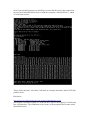
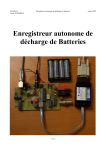
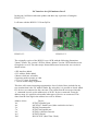
I2C Interface for QL Emulators Part 5
In this part I will deal with some updates and share my experience of using the
BV4221-V2.
I will start with the BV4221-V2 from ByVac.
BV4221-V1
BV4221-V2
The originally version of the BV4221 was a PCB with the following dimensions
32mm x 25mm. The version 2 PCB is 45mm x 40mm. Version 2 PCB also has screw
fixing holes as well. The other major feature differences between the two version is
shown below:• SPI interface added
• I2C address finder added
• Master clock rate selectable
• Inspector mode operates at 100k
• 5V or 3V3 logic switchable
• Two on board voltage regulators
This does offer some interesting opportunities. One of which I have included in my
new routines that is the I2C address finder. By using this, it is possible to check which
I2C devices are connected to the converter. The return from the converter when the
‘x’ command is used, are the address(es) of all I2C devices connected. From the
address range it is possible to determine what types of device are connected. This
done from the first digit in the address hex code as follows:Address in hex
’4x’
‘4x’
‘5x’
‘7x’
‘9x’
‘Ax’
‘D0’
Device
PCF8574 Parallel port
MCP23017 Parallel port (More on this device later)
DS1803 Potentiometer
PCF8574A Parallel port
PCF8591 AD/DA converter
PCF8570 RAM
DS1307 RTC (Real Time Clock)
Note the DS1307 has only one address, unlike the remaining devices, which use the
second digit (x) to select multiple devices on the I2C bus, up to 8 devices with the
devices we having been using in this series.
It is outside to scope of this series of articles, but the BV4221-V2 does have other bus
system, which can be used with the I2C bus system this is called SPI (Serial
Peripheral Interface bus). By the way if you wondering what the I2C (“I squared
Cee”) means it is Inter Integrated Circuit bus. I will not be going in the SPI now, but
may revisit it in a later article. However, the two interfaces are not a million miles
apart in that they are both serial interfaces, the I2C uses two wires, where the SPI bus
uses four. Having said that, the protocols used are very similar. Typical SPI devices
are the same as I2C devices but SPI being much faster is also used on memory
devices and displays. The MMC standard (SD Cards) for example, have an SPI
interface. Could be an interesting project. But after the problems Adrian Ives had with
his SD Card products, not one I will try. So if you understand the workings of one bus
system, it is not a big step to the other. Please see the references below for further
information. The ByVac I2C Foundation pages are a very good place to start.
In my original articles on using the USB to I2C converter I was using version 1 of the
BV4221. Which is now no longer available. Recently I have purchased some
BV4221-V2’s, so could test all my programs using this version. Now in part one of
this series, I did say and I quote, (Please note, I used the original V1 of the BV4221,
ByVac now supply V2 which also has a SPI interface. The commands are the same, so
the programs listed in the article should still work.). Well this remark was made on
the basis of the manual for the BV4221-V2, which I had read, just to make sure there
was nothing that would stop things working. However when it come to trying things
practically it turned out not to be the case. The protocols are nearly the same, but the
BV4221-V2 responses are slightly different. There are subtle differences between the
original BV4221 and the version 2. Which is stated in the BV4221-V2 user manual.
But the manual is not that clear on what these differences are.
This has meant I have had to rewrite the start up routines to reflect these differences.
The first difference is the time it takes for the BV4221-V2 to initialise, this is around
4 seconds. The original converter was virtually instant, or certainly less than 1 second.
Or put another way I never caught myself out with the original converter not being
ready to go when I started things up.
So you will now see that I have put in a couple of PAUSE statements to slow things
down during to first start up stages.
The second difference is that on V1 the end of the received strings was character 32
which is the ‘Space’ character. Which affected my original extract_read_data routine.
The third thing I found was the returns to commands such as ‘V’ which asks for the
version number of the converter was not as expected or the same at the version 1
converter. Also the response to the first CR (carriage return) was also not the same at
the original converter. Now in my original programs I set the converter into decimal
mode. This is where things caused the biggest problems. Since in Hex mode there was
no difference between V1 and V2. In decimal mode on V2 the converter does not
issue a CR after the version number. I informed ByVac and they agree this is a bug,
and will be fixed in the next issue of firmware. However I have no idea when or if this
will happen. So it is better to run the BV4221 in Hex mode. I also found the same
problem with the new commands on V2 such as “x” which returns the addresses if
devices connected to the I2C bus. Useful command this one, as you will see from the
updated program below. So it is best to stay in hex mode. Other than the start up times
and issuing CR’s, there are no differences in using the commands between V1 and
V2.
One other bug I discovered and also reported to ByVac is that in decimal mode,
returns from the converter are getting truncated to two digits. This causes problems in
reading data from devices because any return greater than 99 is now incorrect. So for
example 255 get returned as 55 !!
Because I wrote the original routines in decimal mode, I was not aware the command
strings are case sensitive. So if the hex numbers are sent as is from the SMSQ,
commands such as HEX which returns the letters in upper case, this can cause
problems. For example if you send the line “s A0 p”, what happens is you end up
changing the device address to “00”. Since upper case “A” is the change address
command for the converter. However if you send “s a0 p” then everything is OK. But
note, the converter returns these hex letter digits in upper case, confusing. So you will
find in my revised program below a routine to convert upper case hex letters to lower
case, to be sent to the converter.
I also took the opportunity to improve the user experience and error trapping as well
as running the BV4221-V2 in hex mode only, so as to keep away from the bugs
outlined above. Also I added some features which the version 2 converter has which
the version 1 does not. As always, my programs are just there to show what can be
done, they are not fully developed, just to get you going for guidance and examples of
how to use the I2C bus with this converter.
So you will find the new common routines and start up routine below. As always, I
have commented them so you can see what is going on.
10 REMark I2C test routines
20 I2C_init
30 I2C_Start
40 :
50 PRINT
60 PRINT "LED Flash"
70 ledflash
80 PRINT
90 PRINT "LED Binary Count"
100 ledcount
110 PRINT:PRINT
120 PRINT "Input Test (Press 'Space bar' to exit test"
130 input_test
250 PRINT
260 :
270 PRINT "End
":CLOSE#3:STOP
280 :
1000 DEFine PROCedure I2C_init
1010 CLS
1020 ram1=174:ram1$="AE":REMark PCF8570 address, all address links
open, ie all address pins high
1030 ram2=172:ram2$="AC":REMark PCF8570 address, A2=high, A1=high,
A0=low
1040 ram3=170:ram3$="AA":REMark PCF8570 address, A2=high, A1=low,
A0=high
1050 ram4=168:ram4$="A8":REMark PCF8570 address, A2=high, A1=low,
A0=low
1060 ram5=166:ram5$="A6":REMark PCF8570 address, A2=low, A1=high,
A0=high
1070 ram6=164:ram6$="A4":REMark PCF8570 address, A2=low, A1=high,
A0=low
1080 ram7=162:ram7$="A2":REMark PCF8570 address, A2=low, A1=low,
A0=high
1090 ram8=162:ram8$="A0":REMark PCF8570 address, all address links
closed, ie all address pins low.
1100 parallelA1=126:parallelA1$="7E":REMark PCF8574A address, all
address links open, ie all address pins high
1110 parallelA2=124:parallelA2$="7C":REMark PCF8574A address,
A2=high, A1=high, A0=low
1120 parallelA3=122:parallelA3$="7A":REMark PCF8574A address,
A2=high, A1=low, A0=high
1130 parallelA4=120:parallelA4$="78":REMark PCF8574A address,
A2=high, A1=low, A0=low
1140 parallelA5=118:parallelA5$="76":REMark PCF8574A address, A2=low,
A1=high, A0=high
1150 parallelA6=116:parallelA5$="74":REMark PCF8574A address, A2=low,
A1=high, A0=low
1160 parallelA7=114:parallelA6$="72":REMark PCF8574A address, A2=low,
A1=low, A0=high
1170 parallelA8=112:parallelA7$="70":REMark PCF8574A address, all
address links closed, ie all address pins low
1180 parallel1=78:parallel1$="4E":REMark PCF8574 address, all links
open, ie all address pins high
1190 parallel2=76:parallel2$="4C":REMark PCF8574 address, A2=high,
A1=high, A0=low
1200 parallel3=74:parallel3$="4A":REMark PCF8574 address, A2=High,
A1=low, A0=high
1210 parallel4=72:parallel4$="48":REMark PCF8574 address, A2=High,
A1=low, A0=low
1220 parallel5=70:parallel5$="46":REMark PCF8574 address, A2=low,
A1=high, A0=high
1230 parallel6=68:parallel6$="44":REMark PCF8574 address, A2=low,
A1=high, A0=low
1240 parallel7=66:parallel7$="42":REMark PCF8574 address, A2=low,
A1=low, A0=high
1250 parallel8=64:parallel8$="40":REMark PCF8574 address, all links
closed, ie all address pins low
1260 adda1=158:adda1$="9E":REMark PCF8591 address, all address links
open, ie all address pins high
1270 adda2=156:adda2$="9C":REMark PCF8591 address, A2=high, A1=high,
A0=low
1280 adda3=154:adda3$="9A":REMark PCF8591 address, A2=high, A1=low,
A0=high
1290 adda4=152:adda4$="98":REMark PCF8591 address, A2=high, A1-low,
A0=low
1300 adda5=150:adda5$="96":REMark PCF8591 address, A2=low, A1=high,
A0=high
1310 adda6=148:adda6$="94":REMark PCF8591 address, A2=low, A1=high,
A0=low
1320 adda7=146:adda7$="92":REMark PCF8591 address, a2=low, A1=low,
A0=high
1330 adda8=144:adda8$="90":REMark PCF8591 address, all address links
closed, ie all address pins low.
1340 rtc=208:rtc$="D0":REMark DS1307 real time clock, one fixed
address with this device.
1350 digpot1=94:digpot1$="5E":REMark DS1803 Digital Poteniometer, all
links open, IE all address pins high.
1360 digpot2=92:digpot2$="5C":REMark DS1803 Digital Poteniometer,
A2=high, A1=high, A0=low
1370 digpot3=90:digpot3$="5A":REMark DS1803 Digital Poteniometer,
A2=high, A1=low, A0=high
1380 digpot4=88:digpot4$="58":REMark DS1803 Digital Poteniometer,
A2=high, A1=low, A0=low
1390 digpot5=86:digpot5$="56":REMark DS1803 Digital Poteniometer, A2low, A1=high, A0=high
1400 digpot6=84:digpot6$="54":REMark DS1803 Digital Poteniometer,
A2=low, A1=high, A0=low
1410 digpot7=82:digpot7$="52":REMark DS1803 Digital Poteniometer,
A2=low, A1=low, A0=high
1420 digpot8=80:digpot8$="50":REMark DS1803 Digital Poteniometer, all
links closed, ie all address pins low.
1430 DIM tdata(7)
1440 DIM days$(7,3)
1450 RESTORE
1460 FOR a=1 TO 7
1470 READ d$
1480 days$(a)=d$
1490 NEXT a
1500 DATA "Mon","Tue","Wed","Thu","Fri","Sat","Sun"
1510 END DEFine I2C_init
1520 :
1530 DEFine PROCedure I2C_Start
1540 REMark Utilities for exploring the USB to I2C BV products
1550 REMark -------------------------------------------------1560 REMark Start up
1570 REMark -------------------------------------------------1580 REMark Determine Com Port Number
1590 CLS:PRINT
1600 sererror=0
1610 INPUT "Is USB to I2C connected (Y/N) ";i$
1620 IF i$=="n" THEN PRINT "Program Abborted":STOP
1630 PRINT "Please wait, USBtoI2C is resetting":PAUSE 200:REMark Wait
for power up reset of the USBtoI2C converter to finish, just making
sure the converter is ready.
1640 INPUT "Enter com port number 1,3, etc ";ser$
1650 ser$="Ser"&ser$
1660 PRINT "Opening Com Port ";ser$
1670 DoCom
1680 PRINT "Please wait, ensuring USB to I2C converter ready after
opening Com port"
1690 PAUSE 200:REMark opening serial port, sends USB to I2C converter
into reset. Note the SPI LEDS flash during this process. If you do
not see the flash then the converter may not be fully reset.
1700 PRINT#3;CHR$(13);:REMark Carriage Return to set the baud in the
USB to I2C converter, required on first pass to inialise USB to I2C
converter.
1710 print_reply:print_reply:PRINT " Reply from USB to I2C converter
after sending CR. The print_reply is called twice to handle the first
return from the USB to I2C converter which is an echo of the CR sent"
1720 PRINT#3;CHR$(13);:print_reply:print_reply:PRINT " Reply from
second CR sent, just ignore this"
1730 PRINT
1740 PRINT#3;"V";CHR$(13);:REMark Command to USB to I2C converter for
converter firmware version.
1750 PRINT "Return USB Converter Version Number:-"
1760 non_print_reply:extract_read_data:I2CVer$=d$:PRINT
I2CVer$:non_print_reply
1770 PRINT
1780 REMark print_reply:rem returns a device address in decimal.
1790 PRINT#3;"x";CHR$(13);:REMark This command finds I2C device
adresses on the I2C bus.
1800 PRINT "I2C devices connected to the I2C bus :-"
1810 extract_read_data:PRINT d$:I2CDev$=d$:non_print_reply:REMark
This should return all the device addresses that are on the I2C bus.
1820 decode_I2C_device I2CDev$
1830 display_I2C_devices_found
1840 PRINT
1850 REMark PRINT#3;"D";CHR$(13);:REMark send command to put USB to
I2C Converter into decimal mode. Not recommended with V2 converters.
1860 REMark non_print_reply
1870 REMark PRINT "USBtoI2C Converter now in Decimal mode"
1880 REMark PRINT#3;CHR$(13);
1890 REMark print_reply:rem displays current address in decimal form.
1900 PRINT
1910 END DEFine I2C_Start
1920 :
1930 DEFine PROCedure print_reply
1940 c$=""
1950 REPeat loop
1960 a$=INKEY$(#3)
1970 IF a$="" THEN GO TO 1960
1980 IF a$=CHR$(13) THEN EXIT loop
1990 c$=c$&a$
2000 PRINT a$;
2010 IF a$=">" THEN EXIT loop
2020 END REPeat loop
2030 END DEFine print_reply
2040 :
2050 DEFine PROCedure non_print_reply
2060 c$=""
2070 REPeat loop
2080 a$=INKEY$(#3)
2090 IF a$="" THEN GO TO 2080
2100 b$=a$
2110 c$=c$&b$
2120 IF a$=">" THEN EXIT loop
2130 END REPeat loop
2140 END DEFine non_print_reply
2150 :
2160 DEFine PROCedure extract_read_data
2170 d$=""
2180 REPeat data_loop
2190 a$=INKEY$(#3)
2200 IF a$="" THEN GO TO 2190
2210 IF a$=CHR$(13) THEN EXIT data_loop
2215 IF a$=">" THEN EXIT data_loop
2220 b$=a$
2230 d$=d$&b$
2240 END REPeat data_loop
2250 END DEFine extract_read_data
2260 :
2270 DEFine PROCedure decode_I2C_device (I2CD$)
2280 I2CDev=1:DIM I2CDevices$(10,2):HexC=1:I2CTemp$=""
2290 dlen=LEN(I2CD$)
2300 FOR count=1 TO dlen
2310 IF I2CD$(count)="," THEN I2CDev=I2CDev+1:NEXT count
2320 I2CTemp$=I2CTemp$&I2CD$(count):HexC=HexC+1
2330 IF HexC=3 THEN HexC=1:I2CDevices$(I2CDev)=I2CDevices$
(I2CDev)&I2CTemp$:I2CTemp$=""
2340 NEXT count
2350 arrayt=10-I2CDev:arrayt=(10-arrayt)+1
2360 FOR count=arrayt TO 10
2370 I2CDevices$(count)=" "
2380 NEXT count
2390 END DEFine decode_I2C_device
2400 :
2410 DEFine PROCedure display_I2C_devices_found
2420 PRINT
2430 PRINT "Addresses"
2440 PRINT " Hex Binary
Decimal Type of device"
2450 FOR count=1 TO 10
2460 HexDec=0
2470 I2CDev$=I2CDevices$(count)
2480 HexDec=HEX(I2CDev$)
2490 HexBin$=BIN$(HexDec,8)
2500 IF count >=1 AND count<=9 THEN PRINT count;" "&I2CDev$&"
"&HexBin$&" ";HexDec;"
";
2510 IF count >=10 THEN PRINT count;" "&I2CDev$&" "&HexBin$&"
";HexDec;"
";
2520 IF I2CDev$(1)=" " THEN PRINT "No Device Found"
2530 IF I2CDev$(1)="4" THEN PRINT "PCF8574 or MCP23017 Parallel I/O"
2540 IF I2CDev$(1)="5" THEN PRINT "DS1803 Digital Potentiometer"
2550 IF I2CDev$(1)="7" THEN PRINT "PCF8574A Parallel I/O"
2560 IF I2CDev$(1)="9" THEN PRINT "PCF8591 A/D & D/A"
2570 IF I2CDev$(1)="A" THEN PRINT "PCF8570 256 Byte RAM"
2580 IF I2CDev$(1)="D" THEN PRINT "DS1307 RTC (Real Time Clock)"
2590 NEXT count
2600 END DEFine display_I2C_devices_found
2610 :
2620 DEFine PROCedure DoCom
2630 WHEN ERRor
2640 IF ERR_NI
2650 sererror=1
2660 PRINT "Error opening com port ";ser$
2670 PRINT "No Port open"
2680 END IF
2690 END WHEN
2700 REMark Set the size of the communications buffer to 16K
2710 Combuff=8192*2
2720 OPEN#3;ser$&"ir":REMark i=ignore hardware handshake, r=raw data
2730 BAUD ser$,115200
2740 SER_BUFF ser$,Combuff,Combuff
2750 IF sererror=0 THEN PRINT "Comport "&ser$&" open"
2760 END DEFine DoCom
2770 :
3000 DEFine PROCedure hex_case_con (uhex$)
3010 hex1$=uhex$(1)
3020 hex2$=uhex$(2)
3030 uh1=CODE(hex1$)
3040 IF hex1$>="A" AND hex1$<="F" THEN uh1=uh1+32
3050 uh2=CODE(hex2$)
3060 IF hex2$>="A" AND hex2$<="F" THEN uh2=uh2+32
3070 lhex$=CHR$(uh1)&CHR$(uh2)
3080 END DEFine hex_case_con
3090 :
4000 DEFine PROCedure ledflash
4010 FOR a=1 TO 10
4020 PRINT#3;"s-";parallelA1$;" ff p";CHR$(13);:REMark s=start
message to USB to I2C converter, p=end of message to USB to I2C
converter.
4030 non_print_reply:REMark Stops printing the USB to I2C reply also
ensure serial buffer is cleared.
4040 PAUSE 25
4050 PRINT#3;"s-";parallelA1$;" 00 p";CHR$(13);
4060 non_print_reply:REMark Stops printing the USB to I2C reply also
ensure serial buffer is cleared.
4070 PAUSE 25
4080 NEXT a
4090 END DEFine ledflash
4100 :
5000 DEFine PROCedure ledcount
5010 FOR a=0 TO 255
5020 hhex$=HEX$(a,8)
5030 PRINT a;" ";hhex$;" ";
5040 hex_case_con hhex$:hhex$=lhex$
5050 PRINT#3;"s-";parallelA1$;" "&hhex$&" p";CHR$(13);
5060 non_print_reply:REMark Stops printing the USB to I2C reply also
ensure serial buffer is cleared.
5070 PAUSE 5
5080 NEXT a
5090 END DEFine ledcount
5100 :
6000 DEFine PROCedure input_test
6010 REMark REPeat input_loop
6020 PRINT#3;"s-";parallelA1$;" ff p";CHR$(13);:REMark need to ensure
any lines used as an input are set high.
6030 non_print_reply:REMark Stops printing the USB to I2C reply also
ensure serial buffer is cleared.
6040 hexadd=HEX(parallelA1$):hexadd=hexadd+1:parallelin$=HEX$
(hexadd,8):REMark adds 1 to the HEX device address, for reading data
from the device.
6050 REPeat input_loop
6060 PRINT#3;"s-";parallelin$;" g-1 p";CHR$(13);:REMark reads input
data.
6070 extract_read_data:AT 59,0:PRINT "Data return from selected
device ";d$:non_print_reply
6080 FOR a=1 TO 200:NEXT a
6090 ax=KEYROW(1)
6100 IF ax&&64 THEN EXIT input_loop
6110 END REPeat input_loop
6120 END DEFine input_test
6130 :
Now if you run this program you should get a result like this, this is the return from
my test card, which has all the devices with the exception of the MCP23017, which
we will come to next.
That is all for this time. Next time I will look at a cheaper alternative the PCF8574(A)
parallel device.
References
http://www.byvac.com/bv3/index.php?route=product/product&product_id=88
(Please note, I used the original V1 of the BV4221, ByVac now supply V2 which also
has a SPI interface. The commands are the same, so the programs listed in the article
should still work.)
http://www.byvac.com/bv3/index.php?route=product/category&path=44
PCF8570 Ram Data Sheet
http://www.nxp.com/documents/data_sheet/PCF8570.pdf
PCF8574(A) Data Sheet
http://www.nxp.com/documents/data_sheet/PCF8574.pdf
http://focus.ti.com/lit/ds/symlink/pcf8574.pdf
PCF8591 Data Sheet
http://www.nxp.com/documents/data_sheet/PCF8591.pdf
DS1307 RTC (Real Time Clock)
http://datasheets.maxim-ic.com/en/ds/DS1307.pdf
DS1803 Digital Potentiometer Data Sheet
http://datasheets.maxim-ic.com/en/ds/DS1803.pdf
MCP23017 Data Sheet
http://www.microchip.com/wwwproducts/Devices.aspx?dDocName=en023499
I2C Tutorials
http://www.robot-electronics.co.uk/acatalog/I2C_Tutorial.html
http://www.i2c.byvac.com/ar_foundation.php
http://doc.byvac.com/index.php5?title=I2C_Foundation#SPI
TF Services I2C manual
http://www.dilwyn.me.uk/docs/manuals/index.html
Advanced I2C information, but still worth a read to understand I2C protocols
http://www.nxp.com/documents/user_manual/UM10204.pdf