1
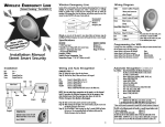
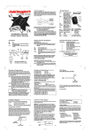
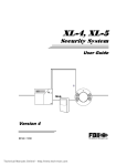
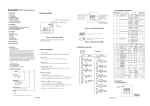
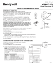
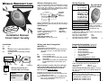
WIRELESS EMERGENCY LINE
Patent Pending - Part #WEL-R
Wireless Emergency Line
Wiring Diagram
Location of the control module is the most important determining factor for range and
reliability of your Wireless Emergency Line. Select a location that is as centrally
located as possible. Keep in mind that your customer will want to control the
operation of the garage door from the driveway, and will also expect the use of the
remote for alarm On/Off in the area of entry and exit.
Green
Recommended
placement for
Wireless
Emergency Line
Attic
Bedroom
Point of Entry
Garage
Basement
Although you can wire at the panel, it may reduce labor and increase range by
installing the Wireless Emergency Line receiver at the point of entry or near a keypad.
Specifications
ith
Now w
larm
atic A
Automognition
Rec
RECEIVER
• 12VDC Power Input
• Selectable: Form C Relay (N/O, N/C, Comm) 5amp
• Channel 1 - Keypad panic data output
(Programmable Medial/Panic)
Frequency 303Mhz
Stand by Power Consumption 15ma
Temperature Range -5°F to 160°F (Indoor use only)
Installation Manual
Street Smart Security
REMOTE CONTROL
Battery (2)
CR1616Lithium
Range 75-100 feet
1
Installation
Wiring and Auto Recognition
Red
Black
Yellow
COMPLETE STEPS 1-5
Step 1) Unplug the receiver from the wire harness.
Step 2) Wire the Red, Black, Yellow and Green to the keypad. (Some panels may
only use 3 wires, refer to page 2, 3 for Caddx and Napco Gem P400,
P600, P800.)
Aux +
Aux Keypad Data Line (Connect to Caddx KP DATA and GREEN from
Gem P400, 600 and 800)
Keypad Data Line (Not used on Caddx and Napco Gem P400,
600, 800)
Black Red
Green
RED
BLACK
GREEN
Alarm Panel
WEL
+ Aux
LED
Green
Yellow
Jumpers
1 2 3
4 5 6
7 8 9
Alarm
Keypad
YELLOW
Program Button
NOTE: Napco Gem P400-800 connect
from yellow of WEL to green of keypad
Options
Optional 2 button remote for both
Medical and Police on one remote.
Part # CEREM2
3
Connect to Keypad Red or Aux (+)
Connect to Keypad Black or Aux (-)
Connect to Keypad Green (Not used on Caddx and Napco Gem P400,
P600 and P800)
Connect to Keypad Yellow. For Caddx connect to KP DATA. (For Napco
Gem P400, P600 and P800 connect yellow from WEL to green of
keypad.)
NOTE: You can make these connections at the panel or at the keypad
itself. If you place the Wireless Emergency Line in the garage or any
other location away from the panel you may choose to wire the
Wireless Emergency Line directly to the keypad.
Step 3) Make sure the alarm panel is powered up and operating.
Step 4) While watching the LED light on the Control module, plug the receiver into
the Wireless Emergency Line harness.
Step 5) The LED will blink 1 time on power up, after 2 seconds COUNT the flashes
that you see. The corresponding flashes will indicate which panel the
Wireless Emergency Line has detected.
4
Connect to green of keypad
(Not used on Caddx or
Napco Gem P400, P600,
P800, Express 400, 600)
Yellow
Connect to yellow of keypad
(Caddx connect to KP DATA)
IMPORTANT: For Napco
Gem P400, P600, P800 and
Express 400, 600 connect
the yellow from the WEL to
the green of the keypad.
Brown
Relay Common (5amp)
Brown/White Relay N/O (5amp)
Blue/Green Relay N/C (5amp)
Red
+12VDC
Black
(-) Ground
Napco Gem P400-800
SEE SPECIAL WIRING
Press and release for relay mode, press
and hold for 3 seconds for PANIC
output. Relay can be wired to any zone
for an additional panic output.
Programming the WEL
To change from Panic to Medical or to change from Delay to Instant activation locate
the two jumpers next to the wire harness.
Jumper closest to the harness IN (Default)
Panic
Jumper closest to the harness removed
Medical
Jumper farthest from the harness IN (Default)
Delay Activation
Jumper farthest from the harness removed
Instant Activation
2
Automatic Recognition Continued:
No. of Flashes Alarm Panel detected by the Wireless Emergency Line
1
No Alarm connected (WEL defaults to relay mode)
SEE PAGE 7 “Default Mode”
2
FBI using a 4600 style keypad
3
FBI using a 4612 style keypad
4
FBI using an addressable keypad SEE PAGE 8
5
Napco 1632, 3200, 9600, P816
6
Caddx NX4, NX6, NX8
7
Napco Gem P400, P600, P800, Express 400, 600
NOTE: If the WEL does not detect correctly,
call Technical Toll Free 888-768-2846 7am-5pm PST
* Please verify the panel is programmed for keypad PANIC or Medical, whichever is being used.
The WEL on the following panels self enrolls as a specific keypad address code.
• Napco 1632, 3200, 9600
Address #2
• FBI Addressable
Address #8 – SEE PAGE 8
DO NOT USE THIS ADDRESS CODE FOR ANY KEYPAD. EXAMPLE: If you are using an
Napco 1632, no keypads can use address #2 since the WEL will automatically enroll
itself as address #2.
Napco 1632, 3200 and 9600 panels must programmed for a second keypad.
For PANIC, you must program that feature “ON” for keypad
#2. The second keypad must be programmed to area #1 for the WEL to operate.
• 1632 Address 0724 (*1) and Address 0731 (*4)
• 3200 Address 2426 (*1) and Address 2441 (*4)
• 9600 Address 2426 (*1) and Address 2441 (*4)
5
This output is a 5amp Form C relay (Common, N/O/, N/C). To energize relay, press
and release remote button. You must RELEASE the button before the relay will
energize. This can be wired to any zone for any response type.
DEFAULT MODE:
• If the WEL fails to recognize any of the data coming from the keypad wires, it will
automatically default to a relay mode for button #1
• If this happens, verify that you are properly wired to one of the alarms listed on
page 5.
• If you have connected the WEL to an alarm it does not recognize, follow the
wiring below to set relay to a zone programmed for panic.
• Program a selected zone as “Keyswitch Arming.”
• Do not use the green or yellow wires.
To Add or Delete Remotes
Hardwiring a Zone
TO ADD A NEW REMOTE
To add a remote to your Wireless Emergency Line PRESS AND RELEASE the
program button on the receiver. The light on the receiver will come ON. Immediately
PRESS the button on the new remote control THREE TIMES. The light on the receiver
should go OFF, indicating the remote has been learned. If the light on the receiver stays
ON, the remote has not been learned. Remove and replace the harness, wait 15 seconds
while auto recognition occurs and follow these instructions again.
Red
Black
Brown/White
Brown
Relay Application
Press and Release button
Press and Hold button 3 for seconds
Relay Output
Panic Mode
Relay Output
Aux +
Aux Zone programmed for any response (Panic/Medical)
Common adjacent to zone
Black
TO DELETE ALL REMOTES
To delete a lost or stolen remote from the Wireless Emergency Line, you must purge the
entire memory. This will delete all of the current remotes. You will then have to add
them back into memory. To purge, PRESS AND HOLD the program button, the light
will come ON for four seconds, then go OFF, and finally it will come ON again, indicating
that all the remotes in memory have been purged. Release the program button and
6
follow the instructions above (To Add a New Remote).
Street Smart Limited Warranty
Street Smart, a Division of Pittway Corporation, and it’s divisions, subsidiaries and affiliates
(“Seller”), 12800 Brook Printer Place, Poway, California 92064, warrants its products to be in
conformance with its own plans and specifications and to be free from defects in materials and
workmanship under normal use and service for 24 months from the date stamp control on the
product or, for products not having a Street Smart date stamp, for 12 months from date of
original purchase unless the installation instructions or catalog sets forth a shorter period, in
which case the shorter period shall apply. Seller's obligation shall be limited to repairing or
replacing, at it s option, free of charge for materials or labor, any product which is proved not in
compliance with Seller's specifications or proves defective in materials or workmanship under
normal use and service. Seller shall have not obligation under this Limited Warranty or
otherwise if the product is altered or improperly repaired or serviced by anyone other than
Street Smart factory service. For warranty service, return product transportation prepaid, to
Street Smart Factory Service, 12800 Brook Printer Place, Poway, California 92064.
THERE ARE NO WARRANTIES, EXPRESS OR IMPLIED, OF MERCHANTABILITY, OR FITNESS FOR A
PARTICULAR PURPOSE OR OTHERWISE, WHICH EXTEND BEYOND THE DESCRIPTION ON THE FACE
HEREOF. IN NO CASE SHALL SELLER BE LIABLE TO ANYONE FOR ANY CONSEQUENTIAL OR INCIDENTAL
DAMAGES FOR BREACH OF THIS OR ANY OTHER WARRANTY, EXPRESS OR IMPLIED, OR UPON ANY
OTHER BASIS OR LIABILITY WHATSOEVER, EVEN IF THE LOSS OR DAMAGE IS CAUSED BY THE SELLER'S
OWN NEGLIGENCE OR FAULT.
Seller does not represent that the products it sells may not be compromised or circumvented; that
the products will prevent any personal injury or property loss by burglary, robbery, fire or otherwise;
or that the products will in all cases provide adequate warning or protection. Customer understands
that a properly installed and maintained alarm may only reduce the risk of a burglary, robbery, fire or
other events occurring without providing an alarm, but it is not insurance or a guarantee that such will
not occur or that there will be no personal injury or property loss as a result. CONSEQUENTLY, SELLER
SHALL HAVE NO LIABILITY FOR ANY PERSONAL INJURY, PROPERTY DAMAGE OR OTHER LOSS BASED
ON A CLAIM THE PRODUCT FAILED TO GIVE WARNING. HOWEVER, IF SELLER IS HELD LIABLE, WHERE
DIRECTLY OR INDIRECTLY, FOR ANY LOSS OR DAMAGE ARISING UNDER THIS LIMITED WARRANTY OR
OTHERWISE, REGARDLESS OF CAUSE OR ORIGIN, SELLER'S MAXIMUM LIABILITY SHALL NOT IN ANY
CASE EXCEED THE PURCHASE PRICE OF THE PRODUCT, WHICH SHALL BE THE COMPLETE AND
EXCLUSIVE REMEDY AGAINST SELLER. This warranty replaces any previous warranties and is the only
warranty made by Seller or this product. No increase or alteration, written or verbal, of the
obligations of this Limited Warranty is authorized.
9
WEL
Resistor should be in-line OR across
the zone, whichever clears the zone.
Brown
Brown/White
NOTE: Blue/Green should be
used instead of Brown/White
for N/C application.
• These FBI panels poll for addressable or non addressable keypads upon power up
OR after you exit programming. Since the WEL requires that you plug it in after the
FBI is powered up, it misses that polling loop.
TO have the FBI panel Re-Poll for keypads and WEL units
Step 1) Enter Programming Mode: Press “CODE” + ”*” and installers code (2468
default) followed by a “1”.
Step 2) Exit Programming by pressing the “STAY” key.
Step 3) The WEL will enroll itself as an Addressable Keypad at address #8
PROBLEM: I press and hold button on remote but there is no panic.
SOLUTION: 1) Make sure the panel is programmed to accept keypad panic
2) Verify that the remote is programmed into the WEL module.
GO TO page 6 and teach the remote.
3) Is the panel programmed for Silent Panic? Maybe it is operating
but you are not hearing it.
4) Is the panel programming to accept extra keypads?
See page 5 for Napco/FBI.
Alarm Panel
Zone programmed
for panic
• When using an addressable keypad like an XK-7LC, XK-5LC, XK-508, XK-512, XK516, XK-708, XK-716 you may have to complete an extra step before the WEL will
operate.
Troubleshooting
Red
The WEL can hold up to seven remotes.
FBI Addressable Keypads
7
STREET SMART SECURITY TECHNICAL CAN BE REACHED AT:
12800 Brook Printer Place, Poway, CA 92064
M-F 7AM-5PM PST AT (888) 768-2846 OR (619) 513-9352-FAX
8
Federal Communications Commission
(FCC) Statement
Canadian Department of
Communications (DOC) Statement
This equipment has been tested to FCC requirements and has been found acceptable for use.
The FCC requires the following statement for your information:
This equipment generates and uses radio frequency energy and if not installed and used
properly, that is, in strict accordance with the manufacturer's instructions, may cause interference to radio and television reception. It has been type tested and found to comply with the
limits for a Class B computing device in accordance with the specifications in Part 15 of FCC
Rules, which are designed to provide reasonable protection against such interference in a residential installation. However, there is no guarantee that interference will not occur in a particular installation. If this equipment does cause interferences to radio or television reception ,
which can be determined by turning the equipment off and on, the user is encouraged to try to
correct the interference by one or more of the following measures:
• If using an indoor antenna, have a quality outdoor antenna installed.
• Reorient the receiving antenna until interference is reduced or eliminated
• Move the receiver away from the control/communicator.
• Move the antenna leads away from any wire runs to the control/communicator.
• Plug the control/communicator into a different outlet so that it and the receiver are on
different branch circuits.
If necessary, the user should consult the dealer or an experienced radio/television
technician for additional suggestions.
The user or installer may find the following booklets prepared by the Federal
Communications Commission helpful: “Interference Handbook”
This booklet is available from the U.S. Government Printing Office, Washington, DC 20402.
The user shall not make any changes or modifications to the equipment unless authorized by
the installation instructions or User’s Manual. Unauthorized changes or modifications could
void the user’s authority to operate the equipment.
NOTICE: The Canadian Department of Communications label identifies certified
equipment. This certification means that the equipment meets certain
telecommunications network protective, operational and safety requirements. The
Department does not guarantee the equipment will operate to the user's satisfaction .
Before installing this equipment, users should ensure that it is permissible to be
connected to the facilities of the local telecommunications company. The equipment
must also be installed using an acceptable method of connection. In some cases, the
company's inside wiring associated with a single line individual service may be
extended by means of certified connector assembly (telephone extension cord). The
customer should be aware that compliance with the above conditions may not prevent
degradation of service in some situations.
Repairs to certified equipment should be made by an authorized Canadian
maintenance facility designed by the supplier. Any repairs or alterations made by the
user to this equipment, or equipment malfunctions, may give the telecommunications
company cause to request the user to disconnect the equipment.
Users should ensure for their own protection that the electrical ground connections
of the power utility, telephone lines and internal metallic water pipe system, if present, are connected together. This precaution may be particularly important to rural
areas.
CAUTION: User should not attempt to make such connections themselves, but should
contact the appropriate electric inspection authority, or electrician, as appropriate.
The Load Number (LN) assigned to each terminal device denotes he percentage of
the total load to be connected to a telephone loop which is used by the device, to
prevent overloading. The termination on a loop may consist of any combination of
devices subject only to the requirement that the total of the Load Numbers of all the
devices does not exceed 100.
11
10