1
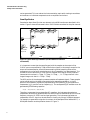
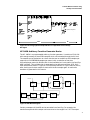
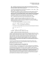
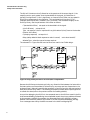
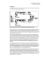
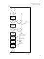
Solutions from HP EEsof
A Flexible Waveform Generator Using
OmniSys and Instrumentation
Product Note E4600-9
Overview
The Series IV OmniSys software now has the capability of interfacing to instruments that
can generate test signals. The flexibility of OmniSys allows a wide variety of signals to be
simulated, which can then be generated by the instruments. This allows systems to be
tested even when some subsystems have not been completed. Applications include
generation of IS-95 CDMA signals, both ideal and those impaired by fading channels.
This product note describes the software and hardware requirements and how they
should be configured. The C-code that implements the interface is described. Examples of
how to generate an ideal IS-95 pilot signal and one that is faded are also provided.
Introduction
This product note describes the interface between the OmniSys system simulator and the
HP 1445A Arbitrary Function Generator (hereafter referred to as the ARB). This
hardware-software link provides a flexible method for generating waveforms. OmniSys
generates samples of the desired waveform; the samples are then fed to the ARB, which
generates the corresponding analogue waveform. Baseband signals can be generated
directly by this method. RF waveforms, such as the IS-95 CDMA or the GSM 0.3GMSK,
can be generated using OmniSys to compute the inphase and quadrature samples of the
waveform, using two ARBs to generate the corresponding analogue waveforms, then using
the HP ESG-D series signal generators to modulate the waveforms to the RF frequency
(see Figure 1).
VXI card cage
HP Unix
workstation
with OmniSys
Inphase component
HPIB
card
Filters (if needed)
Modulator
RF output
Quadrature component
HPIB
controller
ARB
ARB
Figure 1. Setup for Generating RF Signals
With OmniSys, samples of ideal waveforms can be generated, or samples of waveforms
resulting from impairments such as non-linear amplifiers, phase noise, or fading channels
A Flexible Waveform Generator Using
OmniSys and Instrumentation
can be generated. This can reduce the instrumentation required for testing transmitters
and receivers or individual components such as amplifiers and mixers.
OmniSys Basics
Some basics about OmniSys that are relevant to the ARB interface are described in this
section. Figure 2 shows the schematic of an IS-95 CDMA transmitter for the pilot channel.
TStop=26680
TStep-0.203
DSP
RF
Figure 2. Typical OmniSys Schematic (IS-95 CDMA Pilot Channel
Transmitter)
It is important to note that the sampling period of the samples at the output of the
CLOCK source are specified by TStep, and all other signals in this design, except for the
output of the downsampler, have the same sampling period (sampling rates can be
changed only by using multi-rate devices such as an upsampler or a downsampler). The
simulation runs from time 0 to TStop, and the samples of the signal at every node are
indexed with the values 0 • TStep, 1 • TStep, 2 • TStep, ... , N • TStep, where N is the
largest integer such that N • TStep ≤ TStop.
The DSP portion of the schematic processes samples of baseband signals. These samples
can be sent directly to the ARB to generate the corresponding waveform. In the RF
portion of the schematic, signals are represented by the inphase (xi(t)) and quadrature
components (xq(t)), and the carrier frequency (ω). The corresponding RF waveform can be
generated by the following equation
x rf ( t ) = x i ( t ) cos ( ωt ) – x q ( t ) sin ( ωt )
Therefore, to generate the corresponding RF waveform, the inphase and quadrature
components must be first generated with the ARBs, and then modulated up to the carrier
frequency using an HP ESG-D series signal generator. The inphase and quadrature
components of an RF signal can be extracted in OmniSys by using a DEMQAM element.
For example, to generate the signal at the output of the bandpass filter labeled BPFC, a
DEMQAM element must be placed as shown in Figure 3.
2
A Flexible Waveform Generator Using
OmniSys and Instrumentation
Fc=10
In-phase component
Quadrature component
TStop=26680
TStep-0.203
Fc=10
DSP
RF
Figure 3. Extracting Inphase and Quadrature Components of an Omnisys
RF Signal
HP 1445A Arbitrary Function Generator Basics
The HP 1445A is a programmable arbitrary function generator. It contains a 13-bit D/A
with enough memory to store 256K samples, which can be loaded through the VXI bus.
The samples can be clocked out at a clock rate that can be varied from 0.01 samples per
second up to 21.47483648 Msamples per second, with a resolution of less than
0.02 samples per second (a 40-MHz clock is also available, but is not used in the OmniSysARB interface). This variable clock is generated by the reference oscillator, DDS, DAC,
filter combination shown in Figure 4. The ARB clocks data out in a cyclic manner, that is,
after clocking out the last sample it starts with the first sample again. A continuous
waveform is generated in this manner.
10 Mhz
filter
VXI bus
Reference
Oscillator
Memory
13 bit
DAC
DDS
DAC
250 Khz
filter
Filter
Attenuator
clock
clock
Figure 4. ARB Block Diagram
Certain parameters of the ARB can be controlled from OmniSys. For example, the
maximum amplitude of the output can be set to be in the range 0.1 to 5.1V. The output
3
A Flexible Waveform Generator Using
OmniSys and Instrumentation
impedance can be set at either 50 or 75 ohms. If required, the ARB has two filters at its
output; either the 250 kHz or the 10 MHz filter can be selected.
For generating RF signals, two ARBS are required, one for the inphase component and
one for the quadrature component. The ARBs must be synchronized so that they clock out
the data in step. This is automatically done by OmniSys by configuring the ARBs in a
master-slave configuration, where the clock of the master ARB is also used to clock out the
data of the slave ARB. The outputs of the ARBs must then be fed to an HP ESG-D series
signal generator, which modulates the signals to the appropriate carrier frequency.
ESG-D Series Digital Signal Generator Basics
The ESG-D series of digital and analog signal generators can accept inphase and
quadrature inputs and quadrature modulate the signals on to a carrier whose frequency
can be varied up to 4 GHz (different ESG models have different specs, so please refer to
the data sheets for details about a particular model). The full scale input, I 2 + Q 2 , equals
0.5V rms (for certain signals with a large peak to rms value, such as IS-95 CDMA signals,
the peak-to-peak value of each of the I and Q inputs should, at most, be 0.5V). The 1dB
bandwidth of the inphase and quadrature input signals can be up to 10 MHz. The output
magnitude accuracy (rms) is maintained within 0.75 percent over the 4-GHz range; the
phase error (rms) is maintained within 0.5 degrees, the origin offset is less than −40 dBc;
and the EVM (rms) is less than 1 percent.
OmniSys-ARB Interface
The OmniSys interface to the ARB is provided through either the ARB1 or the ARB2
device located in the arb library (see Figure 5). The ARB1 device with one input is the
interface to a single ARB; the ARB2 device with two inputs (one for the inphase
component and one for the quadrature component of the signal) is the interface to two
ARBs in the master-slave mode. The ARB1 interface can be used to generate baseband
signals or RF signals at a low carrier frequency; the ARB2 interface can be used in
conjunction with an HP ESG-D series signal generator to generate RF signals at high
carrier frequencies.
Figure 5. OmniSys-ARB Interface
Because data is sent from the simulator to the ARB through an HPIB bus, the
workstation where the OmniSys simulator runs must be equipped with an HPIB card
(E2071C Plug&Play HPIB Card for HP-UX).
The user-settable parameters for the ARB1 device follow.
Start specifies the time index of the first sample that should be sent to the ARB. If
there is no sample corresponding to this time index, then the sample with the
smallest time index greater than Start is the first sample sent.
4
A Flexible Waveform Generator Using
OmniSys and Instrumentation
Stop specifies the time index of the last sample that should be sent to the ARB. If
there is no sample corresponding to this time index, then the sample with the largest
time index less than Stop is the last sample sent.
The Start and Stop parameters should satisfy the condition 0 ≤ Start < Stop ≤ TStop
(where TStop is specified in the control item).
MaxAmplitude specifies the maximum amplitude of the output signal of the ARB.
The ARB is automatically programmed so that the gain of its output attenuator
equals this value. (The amplitude of the ARB output is independent of the amplitude
of the signal at the input to the ARB device in the simulation.) The input samples are
automatically scaled so that the entire dynamic range of the DAC is used, and the
final output of the ARB is then controlled with the output attenuator.
Filter
specifies the output filter (if any) of the ARB: 250 kHz or 10 MHz.
Impedance
specifies the output impedance of the ARB: 50 or 75 ohms.
DataAvg specifies the method by which the sample points are to be averaged.
Smoothing the data may help in mitigating the effects of any discontinuity between
the first and last points in the data.
•
The 3-point average modifies all data points as follows:
x [ i ] ⇐ ( x [ ( i – 1 )mod L ] + x [ i mod L ] + x [ ( i + 1 )mod L ] ) ⁄ 3 ,
where 0 ≤ i < L, and L is the length of the data array.
•
The end point average modifies only the first and the last data points as follows:
x [ 0 ] ⇐ x [ 0 ] – ( x [ 0 ] + x [ L – 1 ] )2
and
x[ L – 1] ⇐ x[ L – 1] – ((– x[0] + x[ L – 1] ) ⁄ 2)
PrimAddr
SecAddr
specifies the primary address of the ARB
specifies the secondary address of the ARB
The ARB is addressed using the primary and secondary addresses (iopen (hpib, primary
address, secondary address)) where the iopen( ) function is defined in the SICL library. To
check the address of the ARBs, remove the card and check the switch settings. If the
switch settings for the master and slave ARBs are 80 and 88, respectively, then the
SecAddr for the master slave ARBs should be specified as 10 and 11, respectively, in
OmniSys. (In general, the secondary address specified in OmniSys equals the switch
setting divided by 8.) Refer to figure 1-2 on page 1-5 of the ARB manual [3] for details on
the switch settings.
The OmniSys ARB2 device has the same parameters except that the primary and
secondary addresses of both ARBs must be specified (it does not matter which ARB is
designated as the master or the slave).
Practical Considerations for Using the Link
If multirate elements are not used, the minimum value of TStep that can be specified in
an OmniSys simulation is 1/21.47483648 µsec; if multirate elements are used, ensure that
the sampling period of the signal at the input to either the ARB1 or ARB2 devices is
greater than 1/21.47483648 µsec). This is because the maximum clock rate for the ARB is
21.47483648 MHz. Given this maximum sampling rate, the largest bandwidth signal that
can be theoretically generated equals 10.73741824 MHz. However, due to practical
filtering considerations, the actual bandwidth that can be accommodated will be smaller.
Filtering can be done external to the ARB if the 250 kHz and 10 MHz filters available
with the ARB are not suitable for a particular application.
5
A Flexible Waveform Generator Using
OmniSys and Instrumentation
The D/A will introduce a sinc(f) distortion to the spectrum of the output signal. If the
sampling rate is much greater than the bandwidth of the signal, this distortion is
typically not significant. If this is significant, an inverse 1/sinc(f) filter can be created in
OmniSys to compensate for the distortion. This can be done by using the LPFRCI
(lowpass raised cosine filter), located in the Functional Filter Elements category of the
OmniSys library. Set the parameters of this filter as follows:
F (bandwidth of filter)
A (roll-off factor)
set equal to the bandwidth of the signal.
set equal to 0.
Type set equal to Pulse or Impulse with eq. (this adds a 1/sinc(f) term to the transfer
function of the filter).
E (shaping exponent)
set equal to 1.
Delay (delay added to ideal response to make it causal)
set to be at least 4/F.
WindowType select the type of window required.
The schematic in Figure 6 shows how the filters are used in the CDMA design.
F=1.2288
A=0
Type=Pulse
E=1
Delay=4
Figure 6. Using OmniSys Filters to Provide 1/sinc Compensation
Because the ARB outputs the data cyclically, any discontinuities between the last and the
first data points must be avoided. (A discontinuity can cause spurious frequencies in the
analogue signal.) Manually examine the waveform in OmniSys and pick the start and end
data points so that they match. The DataAvg parameter provides some simple algorithms
to smooth the data (refer to the previous section for DataAvg details).
As an aid to debugging the ARB link, the commands sent to the ARB are saved in the file
ArbCommandsDebug_hpibaddr.log, where hpibaddr equals the primary address followed
by the secondary address (for example, the commands sent to the ARB with primary
address 9 and secondary address 10 is saved in the file ArbCommandsDebug_910.log).
Error messages returned by the ARB are saved in the ArbErrorMsgs.log file.
6
A Flexible Waveform Generator Using
OmniSys and Instrumentation
Example 1
The example in Figure 7 illustrates how an ideal pilot tone CDMA signal for the forward
link of the IS-95 standard can be generated.
Figure 7. OmniSys Schematic for Generating an IS-95 CDMA Pilot Signal
The schematic shows a clock that clocks two linear feedback shift registers that generate
the short codes for the I and Q channels of the pilot channel (the pilot channel of the
forward link contains only the short codes; actually the 0th Walsh code, which is all zeros
is used and therefore is not included in the schematic. To generate a traffic channel, the
Walsh code must be considered).
The sampling period of the simulation, TStep, is set such that there are 4 samples per
chip. The down-sample element discards 3 of the samples and the up-sample inserts 3
zeros. The input to the FIR filter now consists of 4 samples per chip, where one sample is
the actual value of the chip and the remaining 3 are zeros. The PN sequences are then
filtered with FIR filters whose tap coefficients are listed in the IS-95 specification. The
outputs of the filters are the inphase and quadrature phase components of the final RF
signal. The FIR outputs are then fed to an ARB2 device, whose outputs are in turn
connected to an HP ESG-D series signal generator and modulated up to the required
frequency.
The sampling period, TStep, in the simulation is chosen to be 0.2034505208333 µsec,
which gives 4 samples per chip. The FIR filters have been specified for this sampling rate.
The bandwidth of the signal at the output of the FIR filters is approximately 600 kHz.
This implies that the lower end of the image of the spectrum will lie at approximately 4.3
MHz (4.3 = (1/0.2034505208333) − 0.6). Therefore, external filters are needed because
neither of the ARB filters will get rid of the image frequencies.
The Start and Stop parameters for the ARB2 element were chosen to cover exactly one
period of the short code to avoid any discontinuity between the last and first points. The
Start parameter was set at 12.0035807 µsec (which corresponds to the 60th sample),
which is larger than the startup transient of the FIR filters. The short code is 32767 chips
long; at 4 samples per chip and a sampling period of 0.2034505208333 µsec, this implies
that the Stop parameter should be set at 26677.65288 µsec (26677.65288 = ((32767*4 - 1)*
0.2034505208333) + 12.0035807).
7
A Flexible Waveform Generator Using
OmniSys and Instrumentation
The Filter parameter is set to None because external filters were used. The MaxAmplitude
parameter is set at 0.16187V (the minimum value that will be accepted by the ARB),
which satisfies the ESG-D4000A requirement that I 2 + Q 2 < 0.5V (rms).
The spectrum of the output of the ARB, modulated up to 100 MHz is shown in Figure 8.
Figure 8. Spectrum of an IS-95 CDMA Pilot Signal
8
A Flexible Waveform Generator Using
OmniSys and Instrumentation
Example 2
The example in Figure 9 takes the ideal CDMA signal, modulates it and transmits it
through a 3-path Rayleigh faded channel. The inphase and quadrature components of the
channel output are extracted and sent to the ARB2 device.
The spectrum of the generated signal (Figure 10) shows the two notches due to the
multipath.
Figure 9. OmniSys Schematic of an IS-95 CDMA Pilot Transmitter with a
3-Path Rayleigh Fading Channel
Figure 10. Spectrum of a 3-Path Rayleigh Faded IS-95 CDMA Pilot Tone
Signal
9
A Flexible Waveform Generator Using
OmniSys and Instrumentation
C-Code Considerations
The ARB1 and ARB2 devices in OmniSys were created as user-defined devices. This
makes it possible for a user to modify the code if needed. You must edit the file arb1.c,
recompile any changes, and rebuild the OmniSys executable (follow the instructions in the
Series IV User-Defined Elements manual on how to add your own elements to OmniSys).
You must also modify the makefile omnisys_sr.make to link in the SICL library, which is
obtained along with the HPIB card for the workstation.
The basic flow of the C-code for the ARB interface devices is shown in Figure 11.
One problem that was encountered while developing the code was a memory problem with
the SICL library function iprintf( ) while sending the array of data points to the ARB. To
avoid this problem, the internal buffering by the SICL functions is turned off (by using the
isetbuf( ) function). This slows down the rate of data transfer between OmniSys and the
ARB.
The commands for the ARB are set up as an array of strings, which are then sent using
the command_exe() function. To program the ARB with options not provided in the
interface, modify the code in the functions setup_arb(), setup_marb() and setup_sarb().
When compiling the code and linking it to the OmniSys archive, the SICL library, sicl.sl or
sicl.a, must also be linked in (for details refer to the SICL Users manual [2]). The make
file, OmniSys.make, should be modified for this.
The algorithm for scaling the input signal simply goes through all the data points, finds
the maximum value of the absolute value of all the data points (say MAX), and multiples
all data points by 5.11875/MAX (the value 5.11875 is the maximum value that can be
output by the DAC).
The data points are then converted into DAC codes, which are unsigned integers, with 0
representing −5.12V, 4096 representing 0V and 8191 representing 5.11875V (see page 7-3
of the ARB manual for details [3]). The double_to_dac() function converts the scaled data
points to the DAC codes. To examine the DAC codes sent to the ARB, change the line at
the top of the arb1.c #file
define DATA_DEBUG 0
to
#define DATA_DEBUG 1
and recompile the code. The data will be saved to the file ArbDataDebug_address.log,
where address is the primary address followed by the secondary address. (If large
amounts of data are being sent, saving the data to file can take a considerable amount of
time.)
10
A Flexible Waveform Generator Using
OmniSys and Instrumentation
Start
Time=0?
Yes
Malloc memory to
store data points
Start<=Time<=
Stop?
No
Exit
functions: arb1() or
arb2()
Yes
Store data point
Time=Stop?
No
Exit
Yes
Reset ARBs
function: setup_arb() for arb1,
setup_marb() and setup_sarb()
for arb2.
Send commands to
initialize ARBs
Rescale data,
convert to DAC
codes, and send to
ARBs
functions: store_signal(),
scale_signal(),
double_to_dac(), and
send_data()
function: run_arb
Send commands to
ARBs to start
generating
waveforms
Exit
Figure 11. ARB Interface Device C-Code Flow
11
A Flexible Waveform Generator Using
OmniSys and Instrumentation
Configuring OmniSys
In order to use the ARB link, you must obtain a new executable for the OmniSys program
(this file is omnisys.bin) and the AEL file that contains the definitions for the ARB1 and
ARB2 symbols (this file is arb.ael).
(These files can be obtained via anonymous ftp to hpeesof.external.hp.com (IP address
192.6.21.2); use anonymous as the login name and your email address as the password; cd
to the directory /distribution/example and get the file test_prj.tar.Z. This compressed tar
file contains omnisys.bin and arb.ael and an OmniSys project that contains the example
for generating the IS-95 CDMA signal. The C-code file arb1.c is also included.)
You can either replace the OmniSys executable that you already have in $EESOF_DIR/
bin with the new executable, or you can place the new executable in the project directory
from which you will be running the program. Correspondingly, you can place the arb.ael
file in the $EESOF_DIR/ael/omnisys directory or in the networks subdirectory of the
project directory (for details, refer to “Configuring the Environment” in the Series IV UserDefined Elements manual).
Hardware and software requirements
•
HP UNIX workstation
•
OmniSys: E4604A
•
HPIB card: E2071C
•
VXI cardcage: E1421B
•
VXI controller card: E1406A
•
2 ARB cards: E1445A
•
Signal generator: ESG-D1000A, ESG-D2000A, ESG-D3000A, or ESG-D4000A
•
Filters: as needed
References
1. A. Oppenheim and R. Schaefer, “Discrete-Time Signal Processing,” Prentice Hall,
1989.
2. “HP Standard Instrument Control Library, Installation and Users’s Guide for HPUX,” Third Edition 1995.
3. “HP 1445A Arbitrary Function Generator, User’s Manual,” Hewlett-Packard, 1992.
12
A Flexible Waveform Generator Using
OmniSys and Instrumentation
NOTES
13
For more information, contact a regional HP
office listed below. Or check your telephone
directory for a local HP sales office.
United States
1-800-452-4844
Canada
905-206-4725
Europe
31-20-547-9900
Japan
0120-421-345
Latin America (Miami, Florida)
305-267-4245/4220
Australia
1-800-629-485 (toll free)
fax: (61-3) 9899-3727
Asia Pacific (Hong Kong)
852-2599-7889
fax: 852-2506-9233
China
86-10 505-0149
fax: 86-10 505-0394
for more information on HP EEsof solutions,
please visit us at our World Wide Web site:
http://www.hp.com/go/hpeesof
Data subject to change
© 1995 Hewlett-Packard Company
Printed in USA PN E4600-8 3/97
5965-8120E