1
2
CONTENTS
- RW-2601P Series
Caution.............................................................. 4
1. Introduction.................................................. 5
2. Features......................................................... 7
3. Technical Specifications.............................. 7
4. Explanation of Frontal Aspect................... 9
5. Test Mode.....................................................11
6. Set Mode ..................................................... 14
7. Calibration Mode ...................................... 17
8. Error message and Trouble shooting ..... 21
- RW-P Series
1. Preface......................................................... 24
2. Features....................................................... 24
3. Technical Specifications............................ 25
4.Application of Dummy Plate .....................27
5. Usage of Connector & Roller .................. 28
3
Caution
⊙ Safety Caution
Make sure to comply with the safety cautions as they are designed to prevent
dangers in advance by using the products safely and properly.
Cautions are categorized into 2 types and the significances of ‘Warning’ and
‘Caution’ are as follows.
Refers to situation that may result in high possibility of substantial danger
including death or serious injuries if the directions are infringed.
Refers to situation that may result in high possibility of injuries or material losses if
the directions are infringed.
1. Never disassemble, repair or modify.
Such will not only exempt the product from warrantee but also cause damages to
the apparatus, electrocution or fire.
2. Do not damage, process or excessively pull, bend or twist the power supply cord.
This may damage the power supply cord and may cause fire or electrocution.
3. Do not place combustible spray or fire in nearby location.
4. Do not water to external aspect of the product of use in humid location. This may
cause insulation to be deteriorated, thereby causing risk of electrocution or fire, or
occurrence of error in weighing.
5. Do not place at location exposed to direct sunlight or near hot objects such as
stove. It may cause fire.
6. Make sure to insert the power supply plug fully in order to prevent the plug from
becoming loose. If the contact is not stable, electrical spark may occur and cause
fire.
4
1. Introduction
Thank you for purchasing the CAS RW(2201P/2401P/2601P)_Series (hereinafter referred
to as RW_Series) weighing indicator.
We have designed this equipment with many advanced features, high quality construction,
and user-friendly menu driven programming. We are confident that you will find the CAS
RW_Series will meet all of your most demanding needs. CAS indicator is shaped firmly and
delicately designed to coincide with the special requirements of several industrial fields and
includes many functions and various external interfaces. Also, it contains help display
functions to be used easily.
Before using RW_Series, It is recommended to read this manual carefully and to apply the
function application fully.
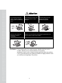
Precautions
Observe the following safety precautions :
Warning
When any damage or defect
occurs, contact your CAS
authorized dealer immediately
for proper repair.
Do not pull the plug by its cord
when unplugging. Damaged
cord could cause electric shock
or fire.
Insert plug firmly to wall outlet to Avoid placing the scale near
prevent electric shock.
heather or in direct sunlight.
To prevent from fire occurring,
Do not place or use the scale
near flammable or corrosive
gas.
5
To reduce electric shock or
incorrect reading, Do not spill
water on the scale or place it in
humid condition.
Attention
For consistent and accurate
reading, maintain periodical
check by your CAS authorized
dealer.
Avoid sudden shock to the scale.
Internal mechanism could by
damaged.
Place the scale on firm and
temperature consistent
environment.
Keep the scale away from the electromagnetic generation devices.
This may interfere with accurate reading.
Attach the rubber pad to the
bottom of the indicator.
Elimination is possible.
Our Dealers : CAS feels that each of its valued customers should get the best service
available. Whether it’s the initial installation of our product,
maintenance/repair work, or simply answering questions about our products,
CAS Corporation and all of its Authorized Dealers are highly trained to assist
you with any need regarding CAS products.
6
2. Features
Features
Up to 6 axle(P/F) scales.
Compact size & light weight Box type.
Built in inner clock for date / time print.
Built in printer.
Built in Battery Charger & Large Capacity Battery. (6V/10A x 2 ea)
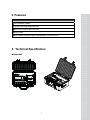
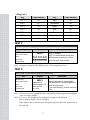
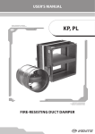
3. Technical Specification
Overview
7
Dimension
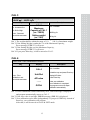
Specification
Model Name
RW2201P/2401P/2601P
RWPrinter Box
Operating Power
Inner Battery Operation. (DC 6V)
Power Source
AC 110/220 V , 50/60 Hz( For Battery Charger))
Display Type
LCD 6 Digit(25mm)
Display Designators
Stable, Zero, Kg/ lb
Product Weight
9.2 kg
8
Built In Printer
Without Display.
6.5 Kg
Accessory
Box
Cable
AC Cord,
Adaptor.
3.5 Kg
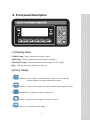
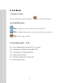
4. Front panel Description
(1) Display lamp
STABLE lamp : Turn on when the weight is stable.
ZERO lamp : Turn on when the current weight is 0 kg(0 lb).
GROSS/NET lamp : Turn on when the current weight is NET weight.
lb/kg : Turn on when the weight unit is lb or kg.
(2) Key Usage
TARE Key : Current weight is memorized as TARE weight. If you press TARE key
in unload condition, tare setting is automatically released.
ZERO Key : Used to return the display to the center of ZERO when the platform is empty.
GROSS/NET Key : Display gross and net weight by turn.
kg/lb Key : Toggles between lb and kg units. (only USA Version)
SUM Key : Used to print sum total weights.
9
PRINT Key : Used to print the current weight.
TURCK No. Key : Used to input the number plate of vehicle which is used to weigh.
Only you can input number within five digits.
PRINT Key : Used to store current condition and exit in CALIBRATION, TEST, SET mode.
P/F 1 Key : Used to display the weight which is connected to Platform 1.
P/F 2 Key : Used to display the weight which is connected to Platform 2.
P/F 3 Key : Used to display the weight which is connected to Platform 3.
P/F 4 Key : Used to display the weight which is connected to Platform 4.
P/F 5 Key : Used to display the weight which is connected to Platform 5.
P/F 6 Key : Used to display the weight which is connected to Platform 6.
(3) How to enter TEST mode
Turn on the Power while pressing the key, and TEST mode starts.
(4) How to enter SET mode
Turn on the Power while pressing the key, and SET mode starts.
(5) How to enter CAL mode
Turn on the Power while pressing the key and press key, and CAL mode starts.
10
5. Test Mode
(1) How to enter
Press the "ON/OFF" key while pressing the
key, and TEST menu starts.
(2) Available keys
Key : Change the set value. Used to increase the set value + 1.
Key : Change the digit of the set value. Used to increase the set value ×10.
Key : Move to the next menu.
(3) Test Menu(TEST 1 - TEST 5)
Test 1 : Key Test
Test 2 : LCD Display Test
Test 3 : Load Cell Test and A/D conversion test
Test 4 : Serial Interface / Printer Test(RS-232)
TEST 1
FUNCTION : Key test
Key
ENTER key :
Move to the next
menu.
Other key :
Perform test.
Display
Description
TEST 1 condition.
tESt 1
Press the key to be test and the
No of key mode should be identify
with code of key.
Key number
ex)In case of Zero key
1
If you press Enter key, it will be moved to
test 2.
11
< Key List >
Key
Code Number
Key
Code Number
P/F 1
03
Tare
05
P/F 2
07
Gross/Net
09
P/F 3
11
kg/lb
13
P/F 4
15
Sum
02
P/F 5
04
Print
06
P/F 6
08
Truck No.
10
Zero
01
Enter
14
TEST 2
FUNCTION : LCD display test
Key
ENTER key :
Move to the next
menu.
Other key :
Perform test.
Display
Description
8.8.8.8.8.8
TEST 2 condition.
TEST 2 is automatically performed.
After this test completing, it will be
▀▀▀▀▀▀▀
moved to test3 automatically.
tESt 2
Ref 1. Program is automatically shifted to test 3 after completing Test 2.
TEST 3
FUNCTION : Load cell test and A/D conversion
Key
ENTER key :
Move to the next
menu.
Other key :
Perform test.
Display
tESt 3
Digital value of
current weight in PF
which you set.
ex) 1 5 0 0
Description
TEST 3 condition
Display digital value of current weight.
This value means converted digital value
under actual condition.
If you press Enter key, it will be moved to
test 4.
Ref 1. A/D converter test is automatically completed by displaying converted digital
value of current weight.
Ref 2. L/C test is also completed by loading the weight on the platform.
Check whether digital value is changing.
If the digital value is fixed or zero is displayed, please check the connection of
the load cell.
12
TEST 4
FUNCTION : Serial Interface / Printer test
Key
ENTER key :
Exit from the Test
Mode
Other key :
Perform test.
Display
Description
Test 4 condition
Press Enter key.
tESt 4
---GOOD
2601P
It will be moved to Normal Mode
after test mode.
Ref 1. Perform test only when the printer connection are installed.
Ref 2. “GOOD” message is displayed if the printer connection and specification is
done correctly. If or not, “ERR 6” message is displayed.
Ref 3. The test output format of printer is as the follows.
TEST OK
If you press the Enter key, it will be returned to NORMAL MODE.
However, only when it is connected with printer, this test can be performed.
* PRINTER FORM *
2010. 8. 25 10:15:20
WEIGHT 1 1200 kg
WEIGHT 2 1200 kg
WEIGHT 3 1100 kg
WEIGHT 4 1100 kg
---------------------------TOTAL 4600 kg
13
6. Set Mode
(1) How to enter
Press the "ON/OFF" key while pressing the
key, and TEST menu starts.
(2) Available keys
Key : Change the set value. Used to increase the set value + 1.
Key : Change the digit of the set value. Used to increase the set value ×10.
Key : Move to the next menu.
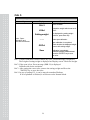
(3) Set Menu(F01 - F14)
F01 : Select Primary Base Unit (kg/lb)-U.S.A version.
F02 : Designation of Serial Port Usage(RS-232C).
F03 : Automatic Zero Tracking Function
F04 : Digital Filter Function.
F13 : Quantity of Scales (P/F, Axle Scale)
F14 : Select Option Clock.
14
Select Primary Base-unit
F01
0
Primary unit is kg
1
Primary unit is lb
Select Primary Base-unit
F02
0
Not used
1
Connection with Serial printer
Automatic Zero Tracking
F03
0
1
~
9
Not used
1 : 0.5 division
~
9 : 4.5 division
Auto zero tracking will automatically
bring the displayed back to “0” when
there are small deviations.
Digital Filter Function
1
1 : Less Vibration
Adjust set value according to the
~
~
F04
condition.
9
9 : Much Vibration
Select the Back-Light Usage
F08
0
Manual Back Light
1
Automatic Back Light
Quantity of Scales
F13
1
One scale
2
Two scales
3
Three scales
4
Four scales
5
Five scales
6
Six scales
15
Select Option Clock
F14
0
Not used
1
Used
Quantity of Scales
Display
▲ : Increase of no.
◀ : Shift of digit.
Enter : Store and
move to the next
menu.
Description
C1 10
YEAR : 10
C2 08
MONTH : 08
C3 25
DAY : 15
C4 13
HOUR : 13
C5 10
MINUTE : 10
C6 01
SECOND : 01
16
7. Calibration Mode
(1) How to enter
Turn on the Power while pressing the
key, and then press
key,
and press Enter key as soon as you selecting the number of platform.
If you don't set the number of platform, it will automatically be moved to Normal
Mode. F13 should be set before entering to CAL mode.
(2) Available keys
Key : Change the set value. Used to increase the set value + 1.
Key : Change the digit of the set value. Used to increase the set value ×10.
Key : Move to the next menu.
(3) Calibration Menu(CAL 1 - CAL 5)
CAL 1 : Maximum Capacity Setting
CAL 2 : Minimum Division Setting
CAL 3 : Setting Weight
CAL 4 : Zero Calibration
CAL 5 : Span Calibration
17
CAL 1
FUNCTION : Maximum Capacity Set
RANGE 1 ~ 99,999 kg/lb
Key
▲ : Increase of no.
◀ : Shift of digit.
Enter : Store and
move to the next menu.
Display
ti. 03
CAL 1
10000
Maximum
Capacity
Value
Description
Program version
CAL 1 condition
10000 kg / lb
Ref 1. The maximum capacity means the maximum weight that scale can measure.
Ref 2. Do not input the resolution, there is no need to input the resolution which is
Automatically calculated.
Ref 3. If you press Enter key, it will be moved to CAL 2.
CAL 2
FUNCTION : Minimum Division Set
RANGE 0.0005 ~ 100 kg/lb
Key
▲ : Input the next division.
Enter : Store and
move to the next menu.
Display
CAL 2
0.01
Minimum
Division
Value
Description
CAL 2 condition
0.01 kg / lb
Ref 1. The minimum division means the value of one division.
Ref 2. External resolution is obtained by division the min. division by the
maximum capacity. Set the resolution to be within 1/10,000.
Ref 3. If you press Enter key, it will be moved to CAL 3.
18
CAL 3
FUNCTION : Setting Weight In Span
RANGE 1 ~ 99,999 kg/lb
Key
▲ : Increase of no.
◀ : Shift of digit.
Enter : Store and
move to the next menu.
Display
CAL 3
Maximum
Capacity of CAL 1
(ex : 10000)
Setting weight
(ex : 100)
Description
CAL 3 condition
10000 kg / lb
100 kg / lb
Ref 1. The weight shall be within the range of 1 % ~ 100 % of maximum weight.
Ref 2. If the Setting Weight is under the 1% of the Maximum Capacity,
Error message ("ERR 22") will occur.
Ref 3. If the Setting Weight over the Maximum Capacity,
Error message ("ERR 23") will occur.
Ref 4. If you press Enter key, it will be moved to CAL 3.
CAL 4
FUNCTION : Zero Calibration Function
Key
Display
CAL 4
Description
CAL 4 condition
Unload the tray and press Enter key
Enter : Zero
Calibration and
move to the next menu.
UnLOAd
A/D value
---GOOd
Display A/D Value.
Press Enter Key.
Under zero calibration
Zero Calibration is completed.
The program moves into Span
Calibration automatically.
Ref 1. If Zero calibration is done without any error, GOOD message is displayed
and program automatically moves to CAL 5.
Ref 2. If the zero value is too high, ERROR message (ERR 26) is displayed.
Ref 3. Zero calibration can be done independently. If you press ZERO key instead of
Enter key, zero calibration will perform.
After that, it will be moved to SAVE & EXIT mode.
19
CAL 5
FUNCTION : Span Calibration Function
Key
Display
CAL 5
LOAd
Setting weight
Enter : Span
calibration and
move to the next menu.
----
GOOd
Save
Description
CAL 5 condition
Unload the weight which was set in
CAL 3.
It is displayed the setting weight.
And then, press Enter key.
Under span calibration.
Span calibration is completed.
Check whether the displayed weight
Is same with setting weight.
Calibration is completed.
Under this condition, release the load.
Press the “ENTER” key to save
the value.
Ref 1. If Span calibration is done without any error, GOOD message is displayed
The weight of setting weight is displayed on Display screen. Check the weight.
Ref 2. If the span is low, Error message (ERR 24) is displayed.
Calibrate with lower resolution.
Ref 3. After setting the exact value, remove the setting weight and Press the
"ENTER" key to save the value.
Ref 4. In case of setting F13, it can be moved to another Platform.
If all of platform is finished, it will be moved to Normal Mode.
20
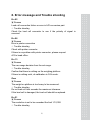
8. Error message and Trouble shooting
Err 02
▣ Reason
Load cell connection failure or error in A/D conversion part.
☞ Trouble shooting
Check the load cell connector to see if the polarity of signal is
reversed.
Err 06
▣ Reason
Error in printer connection
☞ Trouble shooting
Check with printer connector
If there is no problem with printer connector, please request
A/S to head office.
Err 13
▣ Reason
The zero range deviates from the set range.
☞ Trouble shooting
Confirm that there is nothing on the weighing platform.
If there is nothing exist, do calibration in CAL mode.
Over
▣ Reason
The weight on platform is too heavy to be measured.
☞ Trouble shooting
Do not load cell item exceeds the maximum tolerance.
If the load cell is damaged, the load cell should be replaced.
Err 21
▣ Reason
The resolution is set to be exceeded the limit 1/10,000.
☞ Trouble shooting
21
Lower the resolution.
The resolution = allowed weight/one division
Modify the allowed weight in CAL1 or modify the division in CAL2 so
that the resolution should be below 1/10,000.
Err 22
▣ Reason
The weight for span calibration is set to be lower than 10 % of the
maximum capacity of the scale.
☞ Trouble shooting
Set the weight for span calibration in CAL3 to be more than 10% of
the maximum capacity.
Err 23
▣ Reason
The weight for span calibration is set to be exceeded 100 % of the
maximum capacity of the scale.
☞ Trouble shooting
Set the weight for span calibration to be within the maximum capacity
of the scale in CAL 1.
Err 24
▣ Reason
The load cell output is too small at SPAN calibration.
☞ Trouble shooting
Setting of current resolution is not possible due to the error in load cell.
Proceed calibration again with less resolution.
Load cell Sense Voltage
for 5V Excitation Voltage
2 mV
4 mV
10 mV
Recommended Resolution
1/1,000
1/2,000
1/5,000
22
Err 25
▣ Reason
The load cell output is too large at SPAN calibration.
☞ Trouble shooting
Setting of current resolution is not possible due to the error in load cell.
Proceed calibration again with less resolution.
Err 26
▣ Reason
The load cell output is too large at ZERO calibration.
☞ Trouble shooting
Check whether the platform empty.
Proceed calibration again after checking i
23
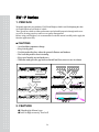
RW-P Series
1. PREFACE
We greatly appreciate your purchase of CAS Road Weigher, which is used for displaying the value
of weight loaded on each shaft of vehicle.
These goods have hold excellent performance and splendid properties through strike tests
as well as devoting ourselves under severe quality management.
Before using road Weigher, It is recommended to read this manual carefully and to apply the
function application fully.
CAUTIONS
- Avoid sudden temperature change.
- Keep it in dry place.
- Use this product the place where the ground is flatness and hardness
- Don’t use this product when it is raining
- Keep out of muddy area and sandy area
- When the sands get in the gap between loadcell and foot, remove to use air cleaner
max 2mm
max 2mm
SAND AREA, CLAY AREA
(To use after cleaning)
max 1°
2. FEATURE
◆ Slim(height 40mm) type
◆ built in high accuracy load cell
24
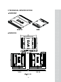
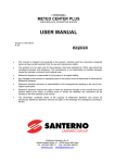
3.TECHNICAL SPECIFICATION
OVERVIEW
DIMENSION
25
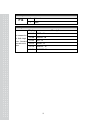
PRODUCT SPECIFICATION
MODEL
RW-01P
RW-05P
RW-10P
RW-15P
Max
1,000 kg
5,000 kg
10,000 kg
15,000 kg
(2,000lb)
(10,000lb)
(20,000lb)
(30,000lb)
Division
-
-
-
10kg
(20lb)
Accuracy
Size
LxW
0.1%
500x400(19.7”x15.7”)
H
WEIGHT
900x500(35.4”x19.7”)
40(1.6”)
15.8kg
30.2kg
◆ OPTION
1) Dummy Plate
- Material : Rubber (NBR)
- Reference : page 33
26
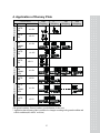
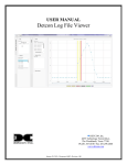
4. Application of Dummy Plate
Clossification
Q’TY
2
A
X
L
E
ACCURACY
PLATE:
2EA
±1~3%
PLATE:
4EA
±0.1%
PLATE:
2EA
DUMMY:
12EA
±1~3%
3
A
PLATE:
X
4EA
L
E
PLATE:
6EA
PLATE:
2EA
4
A DUMMY:
X 12EA
L
E PLATE:
4EA
PLATE:
2EA
5 DUMMY:
A 12EA
X
L
E PLATE:
6EA
First
Weighing
2 nd
Weighing
3 rd
Weighing
4 rd
Weighing
±1~2%
±0.1%
±1~2%
±0.5%
±1~3%
±0.5%
(The ground condition : flatness, hardness, zero declination of close axis)
* Application data of dummy plate is possible to be changed according to the ground condition and
vehicle condition(old vehicle’ occasion)
27
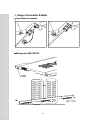
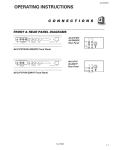
5. Usage of Connector & Roller
Connection of connector
Moving roller (RW-10P,15P)
28
MEMO
29
MEMO
30
31