1
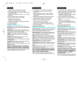
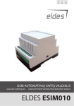
Save a tree...please don't print this document unless you really need to GSM Gate Controller GC500Lite v.1.2 [email protected] / www.orvos.ee Content 1. General information 1.1. Function 1.2. Operation Description 1.3. Technical Specifications 1.4. Connector and LED Indicators Functionality 1.5. Connection Circuit 1.6. System Installation 2. System Pre-operation and the Main Control Commands 2.1. Selecting device language and verification of SMS central number 2.2. Administrator Password Change 2.3. Administrator Numbers 2.3.1. Saving or Changing Administrator Numbers 2.3.2. Verification of Administrator Numbers 2.3.3. Deletion of Administrator Numbers 2.4. User Numbers 2.4.1. Saving User Numbers 2.4.2. Verification of User Numbers 2.4.3. Deletion of User Numbers 2.5. Configuring Output Impulse Duration 2.6. Info on Status SMS (Network Signal Strength, Free Memory Space) 2.7. Allowing Any Phone Number 2.8. Input Status 2.9. Changing input names 2.10. Input enabling/disabling 2.11. Configuring input impulse duration 3. Appendix 3.1. Restoring Default Parameters 3.2. GC500Lite GateControlTools configuration software 3.3. Technical Support 2 5 5 5 6 7 8 8 9 9 9 10 10 10 10 10 11 11 11 11 11 12 12 12 12 12 13 13 13 13 [email protected] / www.orvos.ee User Manual v1.2 Safety instructions Please read and follow these safety guidelines in order to maintain safety of operators and people around: • GSM Gate Controller GC500Lite (later referenced as system) contains a radio transceiver operating in GSM900 and GSM1800 bands • Don’t use the system in hazardous environment • Don’t use the system where it can interfere with other devices and cause any potential danger • Don’t use the system with medical devices • Don’t use the system in hazardous environment • Don’t expose the system to high humidity, chemical environment or mechanical impacts • Don’t attempt to personally repair the system Any system repairs must be done only by qualified, safety aware personnel The system must be powered by external DC 15VA power supply which must be approved by LST-EN 60950-1 standard. Any additional device connected to the GC500Lite system must be powered up by a LST-EN 60950-1 approved supply. External power supply can be connected to AC mains only inside installation room with automatic 2-pole circuit breaker capable of disconnecting circuit in the event of short circuit or over-current condition. Open circuit breaker must have a gap between connections of more than 3mm. Mains power must be disconnected before any installation or tuning work starts. The system installation or maintenance must not be done during stormy conditions. Fuse F1 type - C1S 2.5A. Blown fuse cannot be replaced by the user and the replacement fuses have to be exactly the same as indicated by the manufacturer. The WEEE (Waste Electrical and Electronic Equipment) marking on this product or its documentation indicates that in the EU the product must not be disposed of together with household waste. 3 [email protected] / www.orvos.ee Limited Liability The buyer must agree that the system will reduce the risk of fire, theft, burglary or other dangers but does not guarantee against such events. “Orvos Monitooring LTD” will not take any responsibility regarding personal, property or revenue loss while using the system. “ Orvos Monitooring LTD” responsibility according to local laws does not exceed value of the purchased system. “ Orvos Monitooring LTD” is not affiliated with GSM operators providing cellular services therefore is not responsible for the quality of cellular services. Warranty Warranty period is a 24-month. Warranty period starts from the day the system has been purchased by the end user. The warranty is valid only if the system has been used as inten- ded, following all guidelines listed in the manual and within specified operating conditions. Receipt with purchase date must be kept as a proof. The warranty is voided if the system has been exposed to mechanical impacts, chemicals, high humidity, fluids, corrosive and hazardous environ- ment or other force majeure factors. Content: 1. The system GC500Lite 2. GSM antenna 1 tk. 1 tk. About User Manual. This document describes GSM Gate Controller GC500Lite, its operation and installation. It is very important to read User Manual before start using the system. 4 [email protected] / www.orvos.ee 1. General Information 1.1 Function GC500Lite is a microcontroller based device used to control gate automatics, road barriers or to remotely turn on the electronic device over GSM network. Examples of using the system: • Controlling road barriers in the yards of blocks of flats or offices. • Opening personal house gates. • Turning on an electronic device for a specified period. (E. g., aquarium lighting, turning on the pump, watering, controlling heating in premises etc.). • Turning on the system. • Turning on any electric device controlled with using ON/OFF function. • Rebooting “frozen” system, e. g., computer network or server. • Notification about a fault in gate or other automatics device. 1.2 Operation Description Automatic gate controller system GC500Lite works over GSM network. Gates are opened or any other electronic appliance is turned on by a free phone call. The phone is automatically rejected. On calling to the phone number of the system it checks whether the caller is recorded in the database. If he/she is saved in the system, the relay is turned on for a specified period. The system will ignore requests incoming from an unknown telephone number or an SMS message with a wrong password. Connecting open gates sensor or switch allows administrators receiving SMS message about the gates that did not close during the preset period, for instance, if the gates or road barrier did not close during the particular time period. 5 [email protected] / www.orvos.ee 1.3 Technical Specifications Electrical, mechanical and other specifications Supply voltage Current used in standby model GSM modem frequency Number of outputs Output type Number of “low” level (negative) inputs Number of “high” level (positive) inputs Allowable “low” level (negative) input voltage values Allowable “high” level (positive) input voltage values C1 output maximum commutating values Dimensions Operating temperature range Number of administrators Number of users 6 10-24V ~ 200mA max 10-24V DC ~ 200mA max not more than 50mA 900/1800 MHz 1 NO (relay) 2 1 0-1.6 V 5-50V 1A/24V DC 0,5A/125V AC 70x85x57 mm -20 - +55C 5 500 [email protected] / www.orvos.ee 1.4 Connector and LED Indicators Functionality Fig nr.1 Short explanation of the main units GSM MODEM SIM CARD LED DEFAULT ANT USB Labeling AC/DC Relay Relay GND Z3 Z2 Z1 GSM network 900/1800MHz modem SIM card Light-emitting diodes indicator Connectors (D1 and D2) for restoring default settings GSM antenna SMA type connector Mini USB connector Explanation Power supply pins Galvanically unbound relay connector. Normally open (NO) Galvanically unbound relay connector. Normally open (NO) Ground “Low” level input Z3 “High” level input Z2 “Low” level input Z1 7 [email protected] / www.orvos.ee 1.5 Connection Circuit Note Although the installation of system GC500Lite is not complex, we highly recommend installing the device only in the case if you have minimal electrotechnical or electronics knowledge. Otherwise you can damage the device. Fig nr.2 1.6 System Installation 1. Place SIM card in the holder but make sure that SIM card PIN code is disabled (PIN code can be disabled by putting SIM card into mobile phone and following proper menus). SIM card should not have any remaining SMS messages. 2. Connect the circuit as shown in fig. No 2. Connect control connectors of the gate automatics device to the relay contacts. The systems that are already installed most often contain a button for opening the gates. The relay can be connected instead of the button or in parallel with its contacts. 3. Connect a sensor or switch to inputs Z1-Z3 that turns on only when gates are lifted. Low level signal is connected to Z1 and Z3. High level signal is connected to Z2. (Input connection is an additional function and it is not necessary to install). 4. The system will start in less than a minute. LED indicator should be blinking every five seconds indicating connection to GSM network. If the indicator is blinking very frequently, i. e. several times per second, it is possible that SIM card can is inserted incorrectly or PIN code request is not disabled. 8 [email protected] / www.orvos.ee 2. System Pre-operation and the Main Control Commands !!!Very important!!! Underscore symbol ‘_’ in this manual is used to represent space. When writing SMS messages, every underscore symbol should be replaced by single space symbol. XXXX — means password. Don’t leave any space at the beginning and the end of the message. To set GC500Lite system parameters easier and quicker you can use the computer, USB cable and configuration program GateControlTools. You can read more in chapter 3.2. 2.1 Selecting device language and verification of SMS central number The language in which the device communicates with the user can be chosen before changing factory default password. To change the language in the system that is already configured reset default settings as described in 3.1 appendix. Send SMS message with the required language code to the number of the SIM card inserted in GC500Lite. E.g., if you want to set the English language send the following SMS message: EN. Table of possible languages: Language Code Lithuanian LT English EN Russian RU Estonian EE 30-60 seconds later you should get an SMS message: „English language confirmed.“ Go to chapter 2.2 upon reception of this message. Otherwise check for network connection and call GC500Lite system from your mobile and wait until the system drops the call. You should get an SMS message asking to change default password. Otherwise check for network connection and change SMS central number. SMS central number is saved in SIM card, therefore if SIM card has been used to send SMS messages with a mobile phone, then you don’t’ need to change SMS central number. Often SMS central number is already saved in SIM card by cellular operator. Central number can be entered by sending SMS message: XXXX_SMS_+37211111111 XXXX — is a password. Default password is four zeros: 0000. SMS central number is provided by cellular network provider. Message should be sent to the number of SIM card which is placed into the system. If all went correct, the system will send a message: SMS central number has been successfully changed to +37211111111 2.2 Administrator Password Change All SMS commands start with a password, please memorize it. Manufacturer default password is four zeros 0000, which is necessary to change! Manufacturer default password can be changed by sending the following SMS message to GC500Lite system: 9 [email protected] / www.orvos.ee 0000_PSW_XXXX To replace your password send the following SMS message: YYYY_PSW_XXXX XXXX is any four digit number except four zeros. Non-numerical characters like dots, colons, spaces are not allowed. YYYY is the old system password. If you forgot the password, default manufacturer password can be restored, see chapter 3.1 for more details. 2.3 Administrator Numbers The system GC500Lite allows to pre-program up to five different mobile numbers which will have access to and control the system. NR1 is mandatory while others can be skipped. All numbers must be entered starting with international country code, e. g. national code for Estonia is 372, United Kingdom - 44. The plus sign is not necessary. Numbers without the international code are not allowed. 2.3.1 Saving or Changing Administrator Numbers Send SMS message with the following text: XXXX_NR1:37211111111_NR2:37211111111_NR3:37211111111_NR4:37211111111_N R5:37211111111 Ones should be replaced with administrator numbers. Numbers don’t have to be entered in sequential order right away. E. g. Use can enter first and fourth number by sending the following SMS message: XXXX_NR1:37211111111_NR4:37211111111 Or individually one number at a time: XXXX_NR3:37211111111 Numbers can be changed same way as described above. New number will overwrite old one, therefore no erasing is necessary. 2.3.2 Verification of Administrator Numbers To inquire the system about pre-programmed administrator numbers send the following SMS message: XXXX_HELPNR The system will reply with all pre-programmed numbers. 2.3.3 Deletion of Administrator Numbers To erase a particular or several administrator numbers send an SMS message with the numbers to be deleted: XXXX_NR2:DEL_NR3:DEL_NR4:DEL_NR5:DEL The system will not allow erasing first number NR1. It can only be modified. 2.4 User Numbers The system GC500Lite allows to pre-program up to 500 different mobile numbers which will have access to controlling the gates by a phone call. The gates can also be controlled by administrators. All numbers must be entered starting with international country code, e. g. national code for Estonia is 372. The plus sign is not necessary. Numbers without the international code. The numbers can be recorded or deleted only by administrator.. 10 [email protected] / www.orvos.ee 2.4.1 Saving User Numbers Send SMS message with the following text: XXXX_N:37211111111_37211111111_372......... Ones should be replaced with user numbers. Up to 10 numbers can be entered sending an SMS message. To enter more numbers, send another analogous SMS message. The ten numbers don’t have to be entered in sequential order right away. E. g. use can enter only one number. After saving 500 user numbers you will be able to enter new users after you have deleted the users not using the system thus emptying memory space. 2.4.2 Verification of User Numbers To learn if a particular user number is programmed in the system send the following SMS message: XXXX_T:37211111111 Ones should be replaced with the number which you want to check if it is entered in the system. To see all numbers entered send the following SMS message: XXXX_GETALLNUMBERS NB! Depending on entered user numbers you might receive up to 55 SMS messages! 2.4.3 Deletion of User Numbers To delete a particular or several user numbers send an SMS message with the numbers to be deleted: XXXX_D:37211111111_37211111111_372......... Ones should be replaced with user numbers. Up to 10 numbers can be deleted sending an SMS message. To enter more numbers, send another analogous SMS message. The numbers don’t have to be deleted in sequential order right away. E. g. use can delete only one number. To delete all numbers except administrators send the following SMS message: XXXX_D:ALL 2.5 Configuring Output Impulse Duration The manufacturer set that after the user’s call relay connectors are connected for 2 seconds (impulse duration). To change the duration of switching on the relay end the following SMS message: XXXX_TIMER:t where t means the time of turning on the relay in seconds. Possible t values are [1-10]. Quantization is by 1. E. g. XXXX_TIMER:10 means that relay contacts will be connected for 10 seconds. After 10 seconds the relay will be turned off and the contact will be open, i. e. NO. 2.6 Info on Status SMS (Network Signal Strength, Free Memory Space) The system GC500Lite can any time be inquired about GSM signal strength and free memory space for entering user numbers. Send the following SMS message: XXXX_INFO 11 [email protected] / www.orvos.ee 2.7 Allowing Any Phone Number The system is set so that the relay of the unit can be controlled only by the users entered on the system. However, it is possible turning on a special mode the relay can be turned on by any caller calling to the SIM card number of the device. To turn on this mode send the following SMS message: XXXX_ALLNUM:ON To turn off controlling from any phone send the following SMS message: XXXX_ALLNUM:OFF 2.8 Input Status To find out current input names and their settings send the following SMS message: XXXX_STATUS You will receive the answer, e.g.: “Z1:Zone1:ON/OFF T1:600 Z2:Zone2:ON/OFF T2:600 Z3:Zone3:ON/OFF T3:600”. T1, T2 and T3 — delay of particular input in milliseconds, i. e. a period during which the input starts reacting to signal change. For instance, the alarm will be triggered just in the case when voltage (signal) is supplied for at least 600ms. 2.9 Changing input names Input names set by the manufacturer: Z1- Zone1, Z2-Zone2, Z3-Zone3. Any of these names can be changed by the user. The names cannot repeat or coincide with control commands. Input names can be changed by sending the following SMS message: XXXX_Z2:OpenGate The user can change all names at once, several names or only one name. Maximum input name length is 8 characters. 2.10 Input enabling/disabling Any of the inputs can be enabled by sending the following SMS message: XXXX_Z1:ON_Z2:ON_Z3:ON E. g. XXXX_Z2:ON or XXXX_doors:ON Any of the inputs can be disabled by sending the following SMS message: XXXX_Z1:OFF_Z2:OFF_Z3:OFF E. g. XXXX_Z2:OFF or XXXX_doors:OFF 2.11 Configuring input impulse duration Impulse duration can be changed for any IN1-IN3 input. The input is triggered only if impulse duration is longer than the pre-set value. Duration set by the manufacturer is 600ms. This parameter can be changed for every input or for all inputs at once by sending the following SMS message: XXXX_T1:TT_T2:TT_T3:TT where TT means input reaction time in milliseconds. Possible TT values are 100-42000000. Measuring is by 100. 12 [email protected] / www.orvos.ee E. g. XXXX_T3:300000 means that IN3 input will react only if the impulse was not shorter than 5mins. 3. Appendix 3.1 Restoring Default Parameters 1. 2. 3. 4. 5. disconnect power supply short circuit (connect) connectors D1 and D2 connect power supply for 5 seconds disconnect power supply disconnect connectors D1 and D2 3.2 GC500Lite GateControlTools configuration software To configure the system quicker and easier as well as use more system capabilities use configuration program „GateControlTools” which can be downloaded from our website www.orvos.ee. Before connecting USB cable to the computer read GC500Lite GateControlTools user guide available in the program chapter HELP. 3.3 Technical Support Indication Possible reason Indicator is off or not blinking no external power supply circuit not properly connected blown fuse no network signal Indicator blinking several SIM card is not inserted times per second PIN code hasn’t been disabled Sim card not active System does not send any SIM card account depleted incorrect SIM central number SMS messages or not calling no network signal user number is not programmed in user list Received SMS message “Incorrect Format” incorrect syntax extra space symbol left in SMS message If your problem could not be fixed by the self-guide above, please contact your distributor or Orvos Monitooring tech support by email [email protected] More up to date information about your device and other products can be found at the manufacturer’s website www.orvos.ee. 13