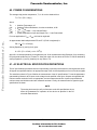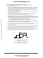
1
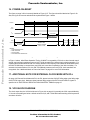
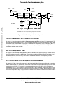
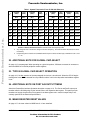
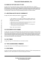
Freescale Semiconductor, Inc. Order this document by MC68330UMAD/AD Microprocessor and Memory Technologies Group MC68330 Addendum to 26 January 1996 1. OPERAND ALIGNMENT AR Y This addendum to the initial release of the MC68330UM/AD User’s Manual provides corrections to the original text, plus additional information not included in the original. This document and other information on this product is maintained on the AESOP BBS, which can be reached at (800) 843-3451 (from the U.S. and Canada) or (512) 891-3650. Configure modem for up to 14.4Kbaud, 8 bits, 1 stop bit, and no parity. Terminal software should support VT100 emulation. Internet access is provided by telneting to pirs.aus.sps.mot.com [129.38.233.1] or through the World Wide Web at http://pirs.aus.sps.mot.com. IM IN On page 3-7, third paragraph (under 3.2.2), change the first two lines to: "The CPU32 restricts all operands (both data and instructions) to be word-aligned. That is, word and long-word operands must be located on a word boundary." Longword operands do not have to be longword aligned. 2. TYPO IN FAST TERMINATION TIMING DIAGRAM EL On page 3-16: UWE and LWE in Figure 3-6 do not assert during a fast termination write. The signals should remain high. 3. ADDITIONAL NOTE ON MBAR DECODE Add to the CPU Space Cycles description on page 3-22: The CPU space decode logic allocates the 256-byte block from $3FF00-3FFFF to the SIM module. An internal two-clock termination is provided by this initial decode for any access to this range, but selection of specific registers depends on additional decode. PR Freescale Semiconductor, Inc... MC68330 Integrated CPU32 Processor User's Manual Accesses to the MBAR register at longword $3FF00 are internal only, and are only visible by enabling show cycles. Users should directly access only the MBAR register and use the LPSTOP instruction to generate the LPSTOP broadcast access to $3FFFE. The remaining address range $3FF04-3FFFD is Motorola reserved and should not be accessed. This document contains information on a product under development. Motorola reserves the right to change or discontinue this product without notice. SEMICONDUCTOR PRODUCT INFORMATION 1996 Motorola, Inc. All Rights Reserved. For More Information On This Product, Go to: www.freescale.com Freescale Semiconductor, Inc. 4. ADDITIONAL NOTES ON CPU SPACE ADDRESS ENCODING On page 3-22, Figure 3-10, the BKPT field for the Breakpoint Acknowledge address encoding is on bits 4-2, and the T bit is on bit 1. The Interrupt Acknowledge LEVEL field is on bits 3-1. 5. BREAKPOINTS On page 3-21, the first paragraph implies that either a software breakpoint (BKPT instruction) or hardware breakpoint can insert an instruction. As noted in the following paragraphs, only a software breakpoint can insert an instruction on the breakpoint acknowledge cycle. AR Y IN Add to the Interrupt Acknowledge Bus Cycles section on page 3-27: Interrupt latency from IRQx asserted to the prefetch of the first instruction in the interrupt handler is about 37 clocks + worst-case instruction length in clocks (using two-clock memory and autovector termination). From the instruction timing tables, this gives 37+71 (DIVS.L with worst-case <fea>) = 108 clocks worst-case interrupt latency time. For applications requiring shorter interrupt response time, use simpler addressing modes and/or avoid using longer instructions (specifically DIVS.L, DIVU.L, MUL.L) to reduce latency. 7. INTERRUPT HOLD TIME AND SPURIOUS INTERRUPTS IM Add to the Interrupt Acknowledge Bus Cycles section on page 3-27: All interrupts (including level 7) are level sensitive and must remain asserted until the corresponding IACK cycle; otherwise, a spurious interrupt exception may result or the interrupt may be ignored entirely. This is also true for external interrupts that are autovectored using either the AVEC signal or the AVEC register, because the SIM will not respond to an interrupt arbitration cycle on the IMB if the external interrupt at that level has been removed. PR EL Freescale Semiconductor, Inc... 6. INTERRUPT LATENCY 8. ADDITIONAL NOTE ON INTERNAL AUTOVECTOR OPERATION Add to the Autovector Interrupt Acknowledge Cycle section on page 3-30: If an external interrupt level is autovectored either by the AVEC register programming or the external AVEC signal, an external IACK will be started and terminated internally. The interrupting device should not respond to this IACK in any way, or the resulting operation is undefined. 9. ADDITIONAL NOTES ON RETRY TERMINATION On page 3-34, Table 3-4: When HALT and BERR are asserted together in case #5 to force a retry of the current bus cycle, relative timing of HALT and BERR must be controlled to avoid inadvertantly causing bus error termination case #3. This can be done several ways: (1) by asserting HALT and BERR either synchronously to the clock to directly controlling which edge each is recognized on, or (2) asynchronously with HALT asserted for time [spec 47A+spec 47B] ns before BERR to guarantee recognition on or before the same clock edge as BERR. 2 MC68330 USER’S MANUAL ADDENDUM For More Information On This Product, Go to: www.freescale.com MOTOROLA Freescale Semiconductor, Inc. 10. NEGATION OF HALT AND BERR FOR RETRY SEQUENCE AND LATE RETRY SEQUENCE. Figure 3-19 and Figure 3-20 on pages 3-37 and 3-38, respectively, should show BERR and HALT being negated one-half clock cycle earlier. 11. ACTIVE NEGATE ON BUS ARBITRATION AR Y 12. ADDITIONAL NOTE ON BUS ARBITRATION PRIORITY For the bus arbitration description beginning on page 3-40: The arbitration priority between possible bus masters for this device is external request via BR (highest priority), then CPU (lowest). IN 13. ADDITIONAL NOTE ON BUS ARBITRATION AND OPERAND COHERENCY IM For the bus arbitration description beginning on page 3-40: Each bus master maintains operand coherency when a higher priority request is recognized. For example, a CPU write of a longword operand to a byte port results in a sequence of four bus cycles to complete the operand transfer—the CPU will not release the bus until the completion of the fourth bus cycle. The RMC read/write sequences for a TAS instruction are also indivisible to guarantee data coherency. Arbitration is allowed between each operand transfer of a multioperand operation such as a MOVEM instruction or exception stacking. PR EL Freescale Semiconductor, Inc... The 68330 actively pulls up all three-stateable bus pins other than the data bus before three-stating them during bus arbitration. This pullup function is not guaranteed to result in spec VOH levels before three-stating, but will help reduce rise time on these signals when using weak external bus pullups. 14. ADDITIONAL NOTES ON RESET INTERACTION WITH CURRENT BUS CYCLE Add to the Reset Operation description beginning page 3-47: Hardware resets are delayed until completion of the current operand transfer for maintaining operand coherency. The processor resets at the end of the bus cycle in which the last portion of the operand is transfered or after the bus monitor has timed out. The bus monitor operates whether or not it is enabled for the time period to which the BMT bits are set. The following reset sources initialize all internal registers to their reset state: external, POR, software watchdog, double bus fault, loss of clock. Execution of a RESET instruction does not effect any of the SIM40 registers or the CPU state. 15. EXTERNAL RESET On page 3-48, Figure 3-27, the RESET signal negates for two clocks between internal and external assertions, not one. RESET is not actively negated and its rise time depends on the pullup resistor used. MOTOROLA MC68330 USER’S MANUAL ADDENDUM For More Information On This Product, Go to: www.freescale.com 3 Freescale Semiconductor, Inc. 16. POWER-ON-RESET The figure on page 3-49 is incorrectly labeled as Figure 3-27. The figure should be labeled as Figure 3-28. Also, the figure is incorrect and should be replaced with Figure 1 below. CLKOUT VCO LOCK 512 × TCLKOUT RESET BUS CYCLES ADDRESS AND CONTROL SIGNALS THREE-STATED BUS STATE UNKNOWN 1 2 3 4 IN NOTES: 1. Internal start-up time. 2. SSP read here. 3. PC read here. 4. First instruction fetched here. ≤ 14 CLOCKS AR Y 328 × TCLKIN IM Figure 1. Initial Reset Operation Timing In Figure 1 above, Initial Reset Operation Timing, CLKOUT is not gated by VCO lock or other internal control signals, and can begin toggling as soon as VCC is high enough for the internal logic to begin operating. For crystal mode and external clock with VCO mode, after the VCO frequency has reached an initial stable value, the 328*TCLKIN delay is counted down, and VCO lock is set after completion of the 328 clock delay. For external clock mode without VCO, the 328*TCLKIN delay starts as soon as EXTAL clock transitions are recognized. See ‘‘Additional Notes on Power-On Reset’’ on page 9 for more POR information. PR EL Freescale Semiconductor, Inc... VCC 17. ADDITIONAL NOTE FOR EXTERNAL CLOCK MODE WITH PLL On page 4-8 External Clock Mode with PLL: the PLL phase locks the CLKOUT falling edge to the falling edge of the EXTAL input clock. Maximum skew between falling edges of the EXTAL and CLKOUT signals is specified in AC ELECTRICAL SPECIFICATIONS CONTROL TIMING on page 15. 18. VCO BLOCK DIAGRAM The clock output from the VCO block shown in Figure 4-4 on page 4-9 is actually the VCO output divided by 2. See the corrected figure below—default values for W,X, and Y SYNCR bits and resulting clock frequencies are shown in italics. 4 MC68330 USER’S MANUAL ADDENDUM For More Information On This Product, Go to: www.freescale.com MOTOROLA Freescale Semiconductor, Inc. XTAL EXTAL VCCSYN XFC 32.768KHz OSC 33.55MHz PHASE COMPARATOR LOW PASS FILTER ÷2 VCO 16.78MHz ÷2 0 SEL SYSTEM CLOCK 8.39MHz 0 X AR Y ÷8 FEEDBACK DIVIDER Y W Default bit values after reset (and resulting frequencies) are shown in italics for VCO operation with a 32.768KHz crystal oscillator circuit. IN Figure 2. Clock Block Diagram for Crystal Operation 19. RECOMMENDED XFC CAPACITOR VALUES IM On page 4-11, second paragraph of 4.2.3.1 Phase Comparator and Filter, and page 7-2, last paragraph: The XFC capacitor recommendation of 0.01µF to 0.1µF applies specifically to crystal mode operation. When using external clock with VCO mode, for frequencies > 1MHz start with a capacitance value of 10000pf/F_MHz. For example, at 16.0MHz the recommended XFC capacitance is approximately 10000pf/16.0 = 625pf—choose the next higher standard value available. PR EL Freescale Semiconductor, Inc... 32.768KHz 2.10MHz 524KHz ÷64 MUX ÷4 MODULUS 1 DIVIDER (1-64) 0 2.10MHz SEL 0 6 $3F MUX 1 20. VCO FREQUENCY LIMIT On page 4-11, last paragraph: although clearing the X bit does affect the system frequency, it has no affect on the VCO frequency because the divider that X controls lies outside the feedback loop. Changing the W or Y bits does change the VCO frequency. Users should consider the maximum VCO frequency limit when programming these bits. 21. CLKOUT AND VCO FREQUENCY PROGRAMMING On page 4-12, Table 4-2 should be replaced by the following full table of frequencies. Although a complete table is shown for all W:X:Y combinations, users must observe both CLKOUT and VCO frequency limits when programming the SYNCR. For example, a system operating frequency (CLKOUT) of 25.16MHz can be selected with W:X:Y=1:1:23, resulting in a VCO frequency of 50.3MHz. However, programming W:X:Y=1:0:47 to achieve the same system frequency would result in a VCO frequency of >100MHz, which is outside the spec VCO frequency operating range. Programming that violates current 25MHz electrical specs is shown in italics. MOTOROLA MC68330 USER’S MANUAL ADDENDUM For More Information On This Product, Go to: www.freescale.com 5 Freescale Semiconductor, Inc. Table 1. System Frequencies From 32.768-kHz Reference VCO (KHZ)1 CLKOUT (KHZ)1 VCO (KHZ)1 W=02 W=02 W=12 W=12 X=0 X=1 X=X 0 131 262 524 524 1049 2097 1 262 524 1049 1049 2097 2 393 786 1573 1573 3 524 1049 2097 4 655 1311 5 786 6 CLKOUT (KHZ) VCO (KHZ) W=0 W=0 W=1 W=1 X=1 X=X X=0 X=1 X=X 32 4325 8651 17302 17302 34603 69206 4194 33 4456 8913 17826 17826 35652 71303 3146 6291 34 4588 9175 18350 18350 36700 73400 2097 4194 8389 35 4719 9437 18874 18874 37749 75497 2621 2621 5243 10486 36 4850 9699 19399 19399 38797 77595 1573 3146 3146 6291 12583 37 4981 9961 19923 19923 39846 79692 918 1835 3670 3670 7340 14680 38 5112 10224 20447 20447 40894 81789 7 1049 2097 4194 4194 8389 16777 39 5243 10486 20972 20972 41943 83886 8 1180 2359 4719 4719 9437 18874 40 5374 10748 21496 21496 42992 85983 9 1311 2621 5243 5243 10486 20972 41 5505 11010 22020 22020 44040 88080 10 1442 2884 5767 5767 11534 23069 42 5636 11272 22544 22544 45089 90178 11 1573 3146 6291 6291 12583 25166 43 5767 11534 23069 23069 46137 92275 12 1704 3408 6816 6816 13631 27263 44 5898 11796 23593 23593 47186 94372 13 1835 3670 7340 7340 14680 29360 45 6029 12059 24117 24117 48234 96469 14 1966 3932 7864 7864 15729 31457 46 6160 12321 24642 24642 49283 98566 15 2097 4194 8389 8389 16777 33554 47 6291 12583 25166 25166 50332 100663 16 2228 4456 8913 8913 17826 35652 48 6423 12845 25690 25690 51380 102760 17 2359 4719 9437 9437 18874 37749 49 6554 13107 26214 26214 52429 104858 18 2490 4981 9961 9961 19923 39846 50 6685 13369 26739 26739 53477 106955 19 2621 5243 10486 10486 20972 41943 51 6816 13631 27263 27263 54526 109052 20 2753 5505 11010 11010 22020 44040 52 6947 13894 27787 27787 55575 111149 21 2884 5767 11534 11534 23069 46137 53 7078 14156 28312 28312 56623 113246 22 3015 6029 12059 12059 24117 48234 54 7209 14418 28836 28836 57672 115343 23 3146 6291 12583 12583 25166 50332 55 7340 14680 29360 29360 58720 117441 24 3277 6554 13107 13107 26214 52429 56 7471 14942 29884 29884 59769 119538 AR Y X=X VCO (KHZ) IN X=1 CLKOUT (KHZ) X=0 6 X=0 Y2 IM CLKOUT (KHZ)1 PR EL Freescale Semiconductor, Inc... Y2 MC68330 USER’S MANUAL ADDENDUM For More Information On This Product, Go to: www.freescale.com MOTOROLA Freescale Semiconductor, Inc. Table 1. System Frequencies From 32.768-kHz Reference CLKOUT (KHZ)1 VCO (KHZ)1 CLKOUT (KHZ)1 VCO (KHZ)1 W=02 W=02 W=12 W=12 X=1 X=X X=0 X=1 X=X 25 3408 6816 13631 13631 27263 54526 26 3539 7078 14156 14156 28312 27 3670 7340 14680 14680 28 3801 7602 15204 29 3932 7864 30 4063 31 4194 CLKOUT (KHZ) VCO (KHZ) CLKOUT (KHZ) VCO (KHZ) W=0 W=0 W=1 W=1 X=0 X=1 X=X X=0 X=1 X=X 57 7602 15204 30409 30409 60817 121635 56623 58 7733 15466 30933 30933 61866 123732 29360 58720 59 7864 15729 31457 31457 62915 125829 15204 30409 60817 60 7995 15991 31982 31982 63963 127926 15729 15729 31457 62915 61 8126 16253 32506 32506 65012 130023 8126 16253 16253 32506 65012 62 8258 16515 33030 33030 66060 132121 8389 16777 16777 33554 67109 63 8389 16777 33554 33554 67109 134218 AR Y X=0 Y2 Some W/X/Y bit combinations shown may select a CLKOUT or VCO frequency higher than spec. Refer to Section 11 Electrical Characteristics for CLKOUT and VCO frequency limits. 2. Any change to W or Y results in a change in the VCO frequency - the VCO should be allowed time to relock if necessary. 3. Programming which violates current 25MHz electrical specs is shown in italics (any combination of W = 1 and Y > 23. IM IN 1. 22. ADDITIONAL NOTE FOR GLOBAL CHIP-SELECT On page 4-13, last paragraph: When operating as a global chip-select, CS0 does not assert for accesses to either the MBAR or to internal peripheral module registers. PR EL Freescale Semiconductor, Inc... Y2 23. TYPO IN GLOBAL CHIP-SELECT OPERATION On page 4-13, the last sentence of the last paragraph is incorrect. It should read “ When the CPU32 begins fetching after reset, CS0 is asserted for every address until the V-bit in the chip-select base address register is set.” 24. ADDITIONAL NOTE ON PORT A/B OUTPUT TIMING Add to the External Bus Interface Operation description on page 4-14: The Port A and Port B output pins transition after the S4 falling edge for the internal write to the respective data register. This places port pin transitions at roughly the same time DS negates for the data register write—note this output delay is not currently specified in the Electrical Specifications. 25. MBAR REGISTER RESET VALUES On page 4-17, the reset values for MBAR bits 31-12 are undefined. MOTOROLA MC68330 USER’S MANUAL ADDENDUM For More Information On This Product, Go to: www.freescale.com 7 Freescale Semiconductor, Inc. 26. MBAR AS7 BIT AND IACK CYCLES On page 4-18, for the second code sequence, change the "MOVE.L #$FFFFF001,D0" to "MOVE.L #$FFFFF101,D0". This sets AS7 in the MBAR to prevent the address decode for the internal 4K register block from responding to CPU space accesses. In particular, it prevents the register block decode of $FFFFFxxx from interfering with IACK cycles (address $FFFFFFFx) and possibly corrupting the vector number returned. This change does not affect normal interrupt acknowledge operation for the internal modules. 27. ADDITIONAL NOTE ON VCO OVERSHOOT A VCO overshoot can occur when increasing the operating frequency by changing the Y bits in the SYNCR register. The following procedure controls the effects of this overshoot: Steps 1 and 2 may be combined. IM 28. BUS ERROR STACK FRAME IN 1. Write the X bit to zero. This will reduce the previous frequency by one half. 2. Write the Y bits to the desired frequency divided by 2. 3. After the VCO lock has occurred, write the X bit to one. This changes the clock frequency to the desired frequency. On page 5-82, in the next-to-last paragraph, delete "(the internal transfer count register is located at SP+$10 and the SSW is located at SP+12)". The stack space allocation is the same for both faults—the location of the internal count register and SSW remains the same. The only difference is that the faulted instruction program counter location SP+10 and SP+12 will contain invalid data. To tell the difference between the two stack frames, look at the first nibble of the faulted exception format vector word located at SP+$E—it will be $0 for the four-word frame and $2 for the six-word frame. PR EL Freescale Semiconductor, Inc... NOTE AR Y On page 4-25, place the following note under the Y-bits description: 29. DSO TIMING On page 5-92, Figure 5-32, DSO transitions one clock later than shown. 30. TYPO ON BDM RSREG COMMAND On page 5-98, Section 5.7.2.8.6, RSREG register bit #8 should be a "1." 31. IPIPE TIMING On page 5-109, Figure 5-38 shows the third IPIPE assertion low, lasting for 1.5 CLKs. It actually asserts for an additional 0.5 CLKs. IPIPE transitions occur after the falling edge of CLKOUT. 8 MC68330 USER’S MANUAL ADDENDUM For More Information On This Product, Go to: www.freescale.com MOTOROLA Freescale Semiconductor, Inc. 32. ADDITIONAL NOTE ON OSCILLATOR LAYOUT GUIDELINES Add to the Processor Clock Circuitry (page 7-1) and Serial Interface (page 7-4) sections: In general, use short connections and place external oscillator components close to the processor. Do not route other signals through or near the oscillator circuit, especially high-frequency signals like CLKOUT and AS. Place a ground shield around the oscillator logic; use a separate trace for ground to the oscillator so that it does not carry any digital switching noise. 33. RECOMMENDED 32KHZ OSCILLATOR CIRCUIT XTAL EXTAL C1 22 pF X1 32.768 kHz IN R2 10 M MC683xx AR Y R1 330 k C2 15 pF IM Figure 3. Sample Crystal Circuit 34. ADDITIONAL NOTES ON POWER-ON RESET Replace Section 7.1.2 Reset Circuitry on page 7-3 with the following paragraphs: PR EL Freescale Semiconductor, Inc... On page 7-2, Figure 7-2, the component values shown in the example 32kHz oscillator circuit may not provide enough loop gain for all crystals. For a more generally robust oscillator circuit, change C1 and C2 as shown below. Users can substitute a10M resistor for the 20M R2 bias resistor as shown. The SIM module generates a power-on reset (POR) when it detects a positive going VCC transition—the VCC threshold is typically in the range 2.0–2.7V and varies depending on processing and environmental variables. Hysteresis is included in the reset circuit to prevent reassertion for a monotonically increasing VCC voltage; however, excessively long VCC rise times (>100 ms) may allow the reset logic to release RESET before VCC has stabilized. Users should not rely on the reset thresholds provided in the SIM to monitor VCC because internal logic may fail at voltages between spec VCCmin and the reset trigger threshold. Instead, use an external low voltage monitor circuit such as the MC34064. When the processor is used in crystal clock mode, the simplest external reset logic consists of simply a 1K pullup resistor from RESET to VCC. This solution relies on a monotonically increasing VCC that has a rise time on the order of 100ms or less—the actual allowable rise time depends on the startup time of the 32.768kHz oscillator circuit. As noted above, this does not provide rigorous VCC monitoring and may be susceptible to sags or glitches in the VCC supply voltage. In external clock mode, either with or without the PLL, the POR time delay of 328 * Tclkin does not provide adequate time for VCC to stabilize before allowing reset to negate. Applications using these two clocking modes should include an external reset circuit that generates an appropriate delay for the power source being used as well as a voltage monitor, if needed. MOTOROLA MC68330 USER’S MANUAL ADDENDUM For More Information On This Product, Go to: www.freescale.com 9 Freescale Semiconductor, Inc. 35. SRAM INTERFACE The SRAM interface shown in Figure 7-4, page 70-3 is incorrect. The corrected drawing is shown below in Figure 4. A15–A1 SIZ0 A0 LWE R/W MCM6206-35 MCM6206-35 AR Y UWE CS1 D15–D0 R/W R/W OE OE CE CE D15–D8 ODD BYTE IN EVEN BYTE D7–D0 Figure 4. SRAM Interface IM 36. ADDITIONAL NOTES ON ROM INTERFACE On page 7-4 Figure 7-5 EPROM interface: Connect OE to CS0 and CE to ground to maximize available access time (at the expense of power consumption). Alternatively, connect OE and CE to CS0 to deselect the EPROM between accesses and lower power consumption. PR EL Freescale Semiconductor, Inc... MC68340 10 MC68330 USER’S MANUAL ADDENDUM For More Information On This Product, Go to: www.freescale.com MOTOROLA Freescale Semiconductor, Inc. 37. STANDARD MC68330 ORDERING INFORMATION Update table 12.1 as shown in Table 2 below. Table 2. Standard MC68330 Ordering Information 5.0 V 3.3 V FREQUENCY (MHZ) ORDER NUMBER 0 – 16 0° C to +70° C MC68330FC16 FC Suffix 0 – 16 -40° C to +85° C MC68330CFC16 0 – 25 0° C to +70° C MC68330FC25 Thin Quad Flat Pack 0 – 16 0° C to 70° C MC68330PV16 PV Suffix 0 – 16 -40° C to +85° C MC68330CPV16 0 – 25 0° C to 70° C MC68330PV25 0 – 16 0° C to +70° C MC68330FC16V 0 – 16 0° C to 70° C MC68330PV16V Plastic Quad Flat Pack FC Suffix 3.3 V TEMPERATURE Plastic Quad Flat Pack Thin Quad Flat Pack IN PV Suffix IM 38. ELECTRICAL CHARACTERISTICS Most of the electrical characteristics are not printed in the MC68330 Integrated CPU32 Processor User’s Manual. They are reprinted here for your convenience. 39. MAXIMUM RATINGS PR EL Freescale Semiconductor, Inc... 5.0 V PACKAGE TYPE AR Y SUPPLY VOLTAGE RATING SYMBOL VALUE UNIT VCC –0.3 to +7.0 V Input Voltage Vin –0.3 to +7.0 V Operating Temperature Range TA 0 to 70 °C Tstg –55 to 150 °C Supply Voltage Storage Temperature Range MOTOROLA The following ratings define a range of conditions in which the device will operate without being damaged. However, sections of the device may not operate normally while being exposed to the electrical extremes. This device contains circuitry to protect against damage due to high static voltages or electrical fields; however, Motorola advises users to take normal precautions to avoid application of any voltages higher than maximum-rated voltages to this high-impedance circuit. Reliability of operation is enhanced if unused inputs are tied to an appropriate logic voltage level (e.g., either GND or VCC). MC68330 USER’S MANUAL ADDENDUM For More Information On This Product, Go to: www.freescale.com 11 Freescale Semiconductor, Inc. 40. POWER CONSIDERATIONS The average chip-junction temperature, TJ, in °C can be obtained from: TJ = TA + (PD • θJA)(1) where: = = = = = Ambient Temperature, °C Package Thermal Resistance, Junction-to-Ambient, °C/W PINT + PI/O ICC x VCC, Watts — Chip Internal Power Power Dissipation on Input and Output Pins — User Determined An approximate relationship between PD and TJ (if PI/O is neglected) is: PD = K ÷ (TJ + 273°C)(2) Solving Equations (1) and (2) for K gives: IN K = PD • (TA + 273°C) + θJA • PD2(3) IM where K is a constant pertaining to the particular part. K can be determined from Equation (3) by measuring PD (at thermal equilibrium) for a known TA. Using this value of K, the values of PD and TJ can be obtained by solving Equations (1) and (2) iteratively for any value of TA. 41. AC ELECTRICAL SPECIFICATION DEFINITIONS The AC specifications presented consist of output delays, input setup and hold times, and signal skew times. All signals are specified relative to an appropriate edge of the clock and possibly to one or more other signals. PR EL Freescale Semiconductor, Inc... For most applications, PI/O < PINT and can be neglected. AR Y TA θJA PD PINT PI/O The waveforms shown in Figure 5 define the measurement of the AC specifications. To test the parameters guaranteed by Motorola, drive inputs to the voltage levels specified in the figure. Outputs are specified with minimum and/or maximum limits, as appropriate, and are measured as shown. Inputs are specified with minimum setup and hold times and are measured as shown. Finally, the measurement for signal-to-signal specifications is shown. NOTE The testing levels used to verify conformance to the AC specifications do not affect the guaranteed DC operation of the device as specified in the DC electrical characteristics. 12 MC68330 USER’S MANUAL ADDENDUM For More Information On This Product, Go to: www.freescale.com MOTOROLA Freescale Semiconductor, Inc. DRIVE TO 2.4 V 2.0 V 2.0 V CLK 0.8 V A DRIVE TO 0.5 V OUTPUTS(1) CLK 0.8 V B VALID OUTPUT n 2.0 V 2.0 V 0.8 V 0.8 V VALID OUTPUT A n+1 B 2.0 V INPUTS(3) CLK DRIVE TO 0.5 V 0.8 V VALID OUTPUT n+1 0.8 V 0.8 V 0.8 V D IN 2.0 V INPUTS(4) CLK 2.0 V 2.0 V VALID INPUT C VALID INPUT 2.0 V 0.8 V DRIVE TO 2.4 V DRIVE TO 0.5 V IM 0.8 V 2.0 V ALL SIGNALS(5) 0.8 V E PR EL Freescale Semiconductor, Inc... D C DRIVE TO 2.4 V 2.0 V AR Y VALID OUTPUT n OUTPUTS(2) CLK F 2.0 V 0.8 V NOTES: 1. This output timing is applicable to all parameters specified relative to the rising edge of the clock. 2. This output timing is applicable to all parameters specified relative to the falling edge of the clock. 3. This input timing is applicable to all parameters specified relative to the rising edge of the clock. 4. This input timing is applicable to all parameters specified relative to the falling edge of the clock. 5. This timing is applicable to all parameters specified relative to the assertion/negation of another signal. LEGEND: A. Maximum output delay specification. B. Minimum output hold time. C. Minimum input setup time specification. D. Minimum input hold time specification. E. Signal valid to signal valid specification (maximum or minimum). F. Signal valid to signal invalid specification (maximum or minimum). Figure 5. Drive Levels and Test Points for AC Specifications MOTOROLA MC68330 USER’S MANUAL ADDENDUM For More Information On This Product, Go to: www.freescale.com 13 Freescale Semiconductor, Inc. 42. DC ELECTRICAL SPECIFICATIONS (See notes (a), (b), (c), and (d) corresponding to part operation, GND = 0 Vdc, TA = 0 to 70°C; see numbered notes) CHARACTERISTIC SYMBOL MIN MAX UNIT Input High Voltage (except clock) VIH 2.0 VCC V Input Low Voltage VIL GND 0.8 V Clock Input High Voltage (EXTAL, X1) VIHC V — — –0.8 V Input Leakage Current (All Input Only Pins) lin –2.5 2.5 µA AR Y Undershoot Vin = VCC or GND Freescale Semiconductor, Inc... 0.7*(VCC) VCC+0.3 Hi-Z(Off-State) Leakage Current (All Non-Crystal Outputs and I/O Pins – See Note 1) Vin=0.5/2.4 V Signal Low Input Current VIL=0.8 V TMS, TDI VIH=2.0 V TMS, TDI Output High Voltage (See Notes 1 and 2) IM Output Low Voltage (See Note 1) 20 µA IL –0.015 0.2 mA IH –0.015 0.2 mA VOH IOH = –0.8 mA, VCC = 4.75 V (All Noncrystal Outputs except HALT, RESET) –20 IN Signal High Input Current IOZ V 2.4 V OL — — V 0.5 IOL = 3.2 mAA23–A0, D15–D0, FC2–FC0, SIZ1, SIZ0 0.5 PR EL IOL = 2.0 mACLKOUT, FREEZE, IPIPE, IFETCH 0.5 IOL = 5.3 mAAll Other Output Only and Group 2 I/O Pins 0.5 IOL = 15.3 mAHALT, RESET Total Supply Current at 5 V +5% @ 16.78 MHz RUN (see Note 3) IDD STOP (VCO Off) SIDD — Power Dissipation at 5 V +5% @ 16.78 MHz PD — Input Capacitance (See Note 1 and 4) Cin — 120 mA 300 µA 630 mW pF All Input-Only Pins 10 All I/O Pins 20 Load Capacitance (See Note 4) CL — 100 pF (a) The electrical specifications in this document for both the 16.78 MHz @ 3.3 V ±0.3 V are preliminary and apply only to the appropriate MC68330V low voltage part. (b) The 16.78-MHz specifications apply to the MC68330 @ 5.0 V ±5% operation. (c) The 25.16 MHz @ 5.0 V ±5% electrical specifications are preliminary. (d) For extended temperature parts TA = –40 to +85∞C. These specifications are preliminary. 14 MC68330 USER’S MANUAL ADDENDUM For More Information On This Product, Go to: www.freescale.com MOTOROLA Freescale Semiconductor, Inc. Input-Only Pins: BERR, BGACK, BKPT, BR, DSACK1, DSACK0, EXTAL, TCK, TDI, TMS Output-Only Pins: A23–A0, AS, BG, CLKOUT, CS3–CS1, DS, FC2–FC0, FREEZE, IFETCH, IPIPE, LWE, RMC, R/W, SIZ1, SIZ0, TDO, UWE Input/Output Pins: Group 1: D15–D0 Group 2: A31–A24, CS0, IRQ7 – IRQ1, MODCK Group 3: HALT, RESET 2. VOH specification for HALT and RESET is not applicable because they are open-drain pins. 3. Supply current measured with system clock frequency of 16.78 MHz. 4. Capacitance is periodically sampled rather than 100% tested. AR Y 1. (See notes (a), (b), (c), and (d) corresponding to part operation, GND = 0 Vdc, TA = 0 to 70∞C; see numbered notes; see Figure 6) CHARACTERISTIC 5.0 V 16.78 MHZ 25.16 MHZ MIN MAX MIN fsys dc 16.78 dc fXTAL 25 50 25 fsys 0.13 16.78 0.13 25.16 MHz On-Chip VCO Frequency Range fVCO 0.1 33.5 0.1 50.3 MHz External Clock Operation fsys 0 16 0 25 MHz trc — 20 — 20 ms System Frequency1 Crystal Frequency PLL Start-up Time2 SYMBOL IM On-Chip VCO System Frequency MAX UNIT 25.16 MHz 50 flimp Limp Mode Clock Frequency3 kHz kHz SYNCR X-bit = 0 — fsys/2 — fsys/2 SYNCR X-bit = 1 — fsys — fsys ∆CLK –1 +1 –1 +1 % tcyc 59.6 — 40 — ns CLKOUT stability4 15 3.3 V OR 5.0 V IN NUM. PR EL Freescale Semiconductor, Inc... 43. AC ELECTRICAL SPECIFICATIONS CONTROL TIMING CLKOUT Period in Crystal Mode 1B6 External Clock Input Period t 62.5 — 40 — ns 1C7 External Clock Input Period with PLL tEXTcyc 62.5 — 40 — ns 2,38 CLKOUT Pulse Width in Crystal Mode tCW 28 — 19 — ns 2B, 3B9 CLKOUT Pulse Width in External Mode tEXTCW 28 — 18 — ns tEXTCW 31 — 20 — ns tCrf — 5 — 4 ns 2C, 3C10 CLKOUT Pulse Width in External w/PLL Mode 4,5 CLKOUT Rise and Fall Times EXTcyc (a) The electrical specifications in this document for both the 8.39 and 16.78 MHz @ 3.3 V ±0.3 V are preliminary and apply only to the appropriate MC68330V low voltage part. (b) The 16.78-MHz specifications apply to the MC68330 @ 5.0 V ±5% operation. MOTOROLA MC68330 USER’S MANUAL ADDENDUM For More Information On This Product, Go to: www.freescale.com 15 Freescale Semiconductor, Inc. All internal registers retain data at 0 Hz. 2. Assumes that a stable VCCSYN is applied, that an external filter capacitor with a value of 0.1 µF is attached to the XFC pin, and that the crystal oscillator is stable. Lock time is measured from power-up to RESET release. This specification also applies to the period required for PLL lock after changing the W and Y frequency control bits in the synthesizer control register (SYNCR) while the PLL is running, and to the period required for the clock to lock after LPSTOP. 3. Determined by the initial control voltage applied to the on-chip VCO. The X-bit in the SYNCR controls a divideby-two scaler on the system clock output. 4. CLKOUT stability is the average deviation from programmed frequency measured at maximum fsys. Measurement is made with a stable external clock input applied using the PLL. 5. All crystal mode clock specifications are based on using a 32.768-kHz crystal for the input. 6. When using the external clock input mode (MODCK reset value = 0 V), the minimum allowable tEXTcyc period will be reduced when the duty cycle of the signal applied to EXTAL exceeds 5% tolerance. The relationship between external clock input duty cycle and minimum tEXTcyc is expressed: Minimum tEXTcyc period = minimum tEXTCW / (50% – external clock input duty cycle tolerance). Minimum external clock low and high times are based on a 45% duty cycle. 7. When using the external clock input mode with the PLL (MODCK reset value = 0 V), the external clock input duty cycle can be at minimum 20% to produce a CLKOUT with a 50% duty cycle. 8. For crystal mode operation, the minimum CLKOUT pulse width is based on a 47% duty cycle. 9. For external clock mode operation, the minimum CLKOUT pulse width is based on a 45% duty cycle, with a 50% duty cycle input clock. AR Y 1. IN Freescale Semiconductor, Inc... (c) The 25.16 MHz @ 5.0 V ±5% electrical specifications are preliminary. (d) For extended temperature parts TA = –40 to +85∞C. These specifications are preliminary. 10. For external clock w/PLL mode operation, the minimum CLKOUT pulse width is based on a 50% duty cycle. IM 11. For external clock mode, there is a 10–40 ns skew between the input clock signal and the output CLKOUT signal from the MC68330. Clock skew is measured from the rising edges of the clock signals. PR EL 12. For external clock mode w/PLL, there is a 5 ns skew between the input clock signal and the output CLKOUT signal from the MC68330. Clock skew is measured from the rising edges of the clock signals. 4 1 2 3 5 NOTES: 1. All timing except two and three is measured with respect to 0.8 V and 2.0 V. 2. Two and three are measured from 1.5 V to 1.5 V. Figure 6. Clock Output Timing Diagram 16 MC68330 USER’S MANUAL ADDENDUM For More Information On This Product, Go to: www.freescale.com MOTOROLA Freescale Semiconductor, Inc. 44. AC TIMING SPECIFICATIONS (See notes (a), (b), (c), and (d) corresponding to part operation, GND = 0 Vdc, TA = 0 to 70∞C; see numbered notes; see Figure 7–Figure 16) 3.3 V OR 5.0 V 16.78 MHZ SYMBOL MIN MAX tCHAV 0 30 NUM CHARACTERISTIC 6 CLKOUT High to Address, FC, SIZ, Valid UNIT ns tCHAVB 0 35 0 25 ns 7 CLKOUT High to Address, Data, FC, SIZ, RMC High Impedance tCHAZx 0 60 0 40 ns 8 CLKOUT High to Address, FC, SIZ, RMC Invalid tCHAZn 0 — 0 — ns 99 CLKOUT Low to AS, DS, CS, UWE, LWE, IFETCH, IPIPE, IACKª Asserted tCLSA 3 30 3 20 ns tSTSA –15 15 –6 6 ns tAVSA 15 — 10 — ns tCLSN 3 30 3 20 ns tSNAI 15 — 10 — ns tSWA 100 — 70 — ns tSWAW 45 — 30 — ns tSWDW 40 — 30 — ns tSN 40 — 30 — ns 9A2 AS to DS or CS Asserted (Read) Address, FC, SIZ, RMC Valid to AS, CS (and DS Read) UWE, LWE 12 Asserted CLKOUT Low to AS, DS, CS, UWE, LWE, IFETCH, IPIPE, IACKª Negated 13 AS, DS, CS, UWE, LWE, IACKª Negated to Address, FC, SIZ Invalid 14 (Address Hold) AS, CS, UWE, LWE, (and DS Read) Width Asserted 14A DS Width Asserted (Write) IN 11 IM 14B AS, CS, UWE, LWE, IACKª (and DS Read) Width Asserted (Fast Termination Cycle) 3 AS, DS, CS, UWE, LWE Width Negated 15 AR Y CLKOUT High to RMC Valid 6A 16 CLKOUT High to AS, DS, UWE, LWE, R/W High Impedance tCHSZ — 60 — 40 ns 17 AS, DS, CS, UWE, LWE Negated to R/W High tSNRN 15 — 10 — ns CLKOUT High to R/W High tCHRH 0 30 0 20 ns CLKOUT High to R/W Low tCHRL 0 30 0 20 ns R/W High to AS, CS Asserted tRAAA 15 — 10 — ns R/W Low to DS Asserted (Write) tRASA 70 — 47 — ns CLKOUT High to Data-Out Valid tCHDO — 30 — 20 ns Data-Out Valid to Negating Edge of AS, CS, UWE, LWE (Fast Termination tDVASN 15 — 10 — ns 25 PR EL Freescale Semiconductor, Inc... 5.0 V 25.16 MHZ MIN MAX 0 20 Write) DS, CS, Negated to Data-Out Invalid (Data-Out Hold) tSNDOI 15 — 10 — ns 26 Data-Out Valid to DS Asserted (Write) tDVSA 15 — 10 — ns 27 Data-In Valid to CLKOUT Low (Data Setup) tDICL 5 — 5 — ns tBELCL 20 — 10 — ns 18 20 219 22 23 24 27A Late BERR, HALT, BKPT Asserted to CLKOUT Low (Setup Time) 28 AS, DS, UWE, LWE Negated to DSACKª, BERR, HALT Negated tSNDN 0 80 0 50 ns 294 DS, CS Negated to Data-In Invalid (Data-In Hold) tSNDI 0 — 0 — ns tSHDI — 60 — 40 ns tCLDI 15 — 10 — ns 29A4 DS, CS Negated to Data-In High Impedance 304 CLKOUT Low to Data-In Invalid (Fast Termination Hold) MOTOROLA MC68330 USER’S MANUAL ADDENDUM For More Information On This Product, Go to: www.freescale.com 17 Freescale Semiconductor, Inc. 44. AC TIMING SPECIFICATIONS (CONTINUED) (See notes (a), (b), (c), and (d) corresponding to part operation, GND = 0 Vdc, TA = 0 to 70∞C; see numbered notes; see Figure 7–Figure 16) 3.3 V OR 5.0 V 16.78 MHZ SYMBOL MIN MAX — 90 tCLDH UNIT ns 315 DSACKª Asserted to Data-In Valid tDADI — 50 — 32 ns 31A DSACKª Asserted to DSACKª Valid (Skew) tDADV — 30 — 20 ns HALT and RESET Input Transition Time tHRrf — 200 — 140 ns 33 CLKOUT Low to BG Asserted tCLBA — 30 — 20 ns 34 CLKOUT Low to BG Negated tCLBN — 30 — 20 ns tBRAGA 1 — 1 — CLK AR Y 32 37 BGACK Asserted to BG Negated 39 BG Width Negated 39A BG Width Asserted 46 tGAGN 1 2.5 1 2.5 OUT CLK tGH 2 — 2 — OUT CLK 1 — 1 — OUT CLK IN 356 BR Asserted to BG Asserted (RMC Not Asserted) tGA tRWA 150 — 100 — OUT ns tRWAS 90 — 60 — ns tAIST 8, 5 — 5 — ns tAIHT 15 — 10 — ns tDABA — 30 — 20 ns Data-Out Hold from CLKOUT High tDOCH 0 — 0 — ns CLKOUT High to Data-Out High Impedance tCHDH — 30 — 20 ns R/W Asserted to Data Bus Impedance Change tRADC 40 — 25 — ns RESET Pulse Width (Reset Instruction) tHRPW 512 — 512 — CLK tRPWI 590 — 590 — OUT CLK BERR Negated to HALT Negated (Rerun) tBNHN 0 — 0 — OUT ns R/W Width Asserted (Write or Read) IM 46A R/W Width Asserted (Fast Termination Write or Read) 47A8 Asynchronous Input Setup Time 47B Asynchronous Input Hold Time 485,7 DSACKª Asserted to BERR, HALT Asserted 70 PR EL Freescale Semiconductor, Inc... NUM CHARACTERISTIC 4 CLKOUT Low to Data-In High Impendance 30A 5.0 V 25.16 MHZ MIN MAX — 60 CLKOUT Low to Data Bus Driven (Show Cycle) tSCLDD 0 30 0 20 ns 71 Data Setup Time to CLKOUT Low (Show Cycle) tSCLDS 15 — 10 — ns 72 Data Hold from CLKOUT Low (Show Cycle) tSCLDH 10 — 6 — ns 80 DSI Input Setup Time t 15 — 10 — ns 81 DSI Input Hold Time t 10 — 6 — ns 82 DSCLK Setup Time t 15 — 10 — ns 83 DSCLK Hold Time t 10 — 6 — ns 53 54 55 56 56A RESET Pulse Width (Input from External Device) 57 18 DSISU DSIH DSCSU DSCH MC68330 USER’S MANUAL ADDENDUM For More Information On This Product, Go to: www.freescale.com MOTOROLA Freescale Semiconductor, Inc. 44. AC TIMING SPECIFICATIONS (CONTINUED) (See notes (a), (b), (c), and (d) corresponding to part operation, GND = 0 Vdc, TA = 0 to 70∞C; see numbered notes; see Figure 7–Figure 16) CHARACTERISTIC DSOD 85 DSCLK Cycle t 86 CLKOUT High to FREEZE Asserted 87 CLKOUT High to FREEZE Negated 88 CLKOUT High to IFETCH High Impedance 89 CLKOUT High to IFETCH Valid DSCCYC t 0 25 — 50 2 0 AR Y FRZA 2 5.0 V 25.16 MHZ MIN MAX UNIT — tcyc + ns t FRZN t IFZ t IF 16 — CLK 35 OUT ns 0 50 0 35 ns 0 50 0 35 ns 0 50 0 35 ns IN (a) The electrical specifications in this document for both the 8.39 and 16.78 MHz @ 3.3 V ±0.3 V are preliminary and apply only to the appropriate MC68330V low voltage part. (b) The 16.78-MHz specifications apply to the MC68330 @ 5.0 V ±5% operation. (c) The 25.16 MHz @ 5.0 V ±5% electrical specifications are preliminary. (d) For extended temperature parts TA = –40 to +85°C. These specifications are preliminary. 1. All AC timing is shown with respect to 0.8 V and 2.0 V levels unless otherwise noted. This number can be reduced to 5 ns if strobes have equal loads. 3. If multiple chip selects are used, the CS width negated (#15) applies to the time from the negation of a heavily loaded chip select to the assertion of a lightly loaded chip select. 4. These hold times are specified with respect to DS or CS on asynchronous reads and with respect to CLKOUT on fast termination reads. The user is free to use either hold time for fast termination reads. 5. If the asynchronous setup time (#47) requirements are satisfied, the DSACK≈ low to data setup time (#31) and DSACK≈ low to BERR low setup time (#48) can be ignored. The data must only satisfy the data-in to CLKOUT low setup time (#27) for the following clock cycle: BERR must only satisfy the late BERR low to CLKOUT low setup time (#27A) for the following clock cycle. 6. To ensure coherency during every operand transfer, BG will not be asserted in response to BR until after cycles of the current operand transfer are complete and RMC is negated. 7. In the absence of DSACKª, BERR is an asynchronous input using the asynchronous setup time (#47). 8. Specification #47A for 16.78 MHz @ 3.3 V ±0.3V will be 8 ns. 9. During interrupt acknowledge cycles up to two wait states may be inserted by the processor between states S0 and S1. IM 2. PR EL Freescale Semiconductor, Inc... NUM 84 DSO Delay Time 3.3 V OR 5.0 V 16.78 MHZ SYMBOL MIN MAX — tcyc + t 10. Address Access Time = 2tcyc + tCW – tCHAV – tDICL = 112.2 ns (@ 16.78-MHz clock). Chip-Select Access Time = 2tcyc – tCLSA – tDICL = 84.2 ns (@ 16.78-MHz clock). MOTOROLA MC68330 USER’S MANUAL ADDENDUM For More Information On This Product, Go to: www.freescale.com 19 Freescale Semiconductor, Inc. S0 S1 S2 S3 S4 S5 CLKOUT 6 6A 8 A31–A0, FC2–FC0, SIZ1–SIZ0 RMC 11 14 AS 12 Freescale Semiconductor, Inc... DS 9A CS 18 21 13 AR Y 9 20 R/W IN 46 UWE, LWE 47A D15–D0 PR EL BERR IM DSACK1, DSACK0 28 29 31 29A 27 48 27A HALT 9 12 12 IFETCH 47A 47B ASYNCHRONOUS INPUTS 27A BKPT NOTE: All timing is shown with respect to 0.8V and 2.0V levels. Figure 7. Read Cycle Timing Diagram 20 MC68330 USER’S MANUAL ADDENDUM For More Information On This Product, Go to: www.freescale.com MOTOROLA Freescale Semiconductor, Inc. S1 S0 S3 S2 S4 S5 CLKOUT 6A 6 8 A31–A0, FC2–FC0, SIZ1–SIZ0 RMC 11 15 14 12 9 DS CS 20 13 14A 22 17 IN R/W 46 UWE, LWE 28 DSACK1, DSACK0 IM 47A 25 55 D15–D0 PR EL Freescale Semiconductor, Inc... 9 AR Y AS 53 23 54 26 BERR 48 27A HALT BKPT NOTE: All timing is shown with respect to 0.8V and 2.0V levels. Figure 8. Write Cycle Timing Diagram MOTOROLA MC68330 USER’S MANUAL ADDENDUM For More Information On This Product, Go to: www.freescale.com 21 Freescale Semiconductor, Inc. S0 S1 S4 S0 S5 CLKOUT 8 6 A31–A0, FC2–FC0, SIZ1–SIZ0 RMC 9 14B AS Freescale Semiconductor, Inc... DS CS 18 R/W 46A 27 AR Y 12 IN 30 D15-D0 27A IM BKPT 30A PR EL Figure 9. Fast Termination Read Cycle Timing Diagram 22 MC68330 USER’S MANUAL ADDENDUM For More Information On This Product, Go to: www.freescale.com MOTOROLA Freescale Semiconductor, Inc. S0 S1 S4 S0 S5 CLKOUT 8 6 A31–A0, FC2–FC0, SIZ1–SIZ0 RMC 12 9 DS CS 20 46A IN R/W UWE, LWE D15-D0 BKPT IM 23 27A 24 18 25 Figure 10. Fast Termination Write Cycle Timing Diagram PR EL Freescale Semiconductor, Inc... 14B AR Y AS MOTOROLA MC68330 USER’S MANUAL ADDENDUM For More Information On This Product, Go to: www.freescale.com 23 Freescale Semiconductor, Inc. S0 S1 S2 S3 S4 S5 CLKOUT A31–A0 7 D15–D0 AS AR Y 16 Freescale Semiconductor, Inc... UWE, LWE DS R/W IN DSACK0 DSACK1 BR PR EL BG IM 47A 35 39A 33 34 BGACK 37 Figure 11. Bus Arbitration Timing—Active Bus Case 24 MC68330 USER’S MANUAL ADDENDUM For More Information On This Product, Go to: www.freescale.com MOTOROLA Freescale Semiconductor, Inc. CLKOUT A31–A0 7 D15–D0 AS 47A 47A BR 37 35 BG 34 47A IN 33 BGACK IM Figure 12. Bus Arbitration Timing—Idle Bus Case PR EL Freescale Semiconductor, Inc... UWE, LWE AR Y 16 MOTOROLA MC68330 USER’S MANUAL ADDENDUM For More Information On This Product, Go to: www.freescale.com 25 Freescale Semiconductor, Inc. S41 S0 S42 S43 S1 S0 S2 CLKOUT 8 6 A31–A0 18 R/W 20 Freescale Semiconductor, Inc... AS 12 AR Y UWE, LWE 15 9 DS 70 72 71 D15–D0 IN 27A BKPT START OF EXTERNAL CYCLE IM SHOW CYCLE PR EL Figure 13. Show Cycle Timing Diagram 26 MC68330 USER’S MANUAL ADDENDUM For More Information On This Product, Go to: www.freescale.com MOTOROLA Freescale Semiconductor, Inc. 0–2 CLOCKS * S0 S1 S2 S3 S4 S5 CLKOUT 6 SIZ1–SIZ0 FC3–FC0 A31–A0 8 11 14 AS 13 9 12 AR Y DS IACKx 18 20 21 R/W 46 31A IN DSACK0 D15-D0 47A 31 IM DSACK1 28 29 29A 27 PR EL Freescale Semiconductor, Inc... 9A * Up to two wait states may be inserted by the processor between states S0 and S1. Figure 14. IACK Cycle Timing Diagram MOTOROLA MC68330 USER’S MANUAL ADDENDUM For More Information On This Product, Go to: www.freescale.com 27 Freescale Semiconductor, Inc. CLKOUT FREEZE 83 82 BKPT/DSCLK 85 81 80 AR Y IFETCH/DSI Freescale Semiconductor, Inc... 84 IPIPE/DSO CLKOUT 86 IFETCH/DSI 88 IM FREEZE IN Figure 15. Background Debug Mode Serial Port Timing 87 89 PR EL Figure 16. Background Debug Mode FREEZE Timing 28 MC68330 USER’S MANUAL ADDENDUM For More Information On This Product, Go to: www.freescale.com MOTOROLA Freescale Semiconductor, Inc. IEEE 1149.1 ELECTRICAL SPECIFICATIONS (See notes (a), (b), (c), and (d) corresponding to part operation, GND = 0 Vdc, TA = 0 to 70°C(see Figures 20, 21, and 22) UNIT MHz ns ns ns ns ns ns ns ns ns ns ns AR Y 5.0 V 25.16 MHZ MIN MAX 0 25 40 — 18 — 0 3 10 — 18 — 0 26 0 40 10 — 10 — 0 16 0 16 IN 1 2 3 6 7 8 9 10 11 12 13 CHARACTERISTIC TCK Frequency of Operation TCK Cycle Time in Crystal Mode TCK Clock Pulse Width Measured at 1.5 V TCK Rise and Fall Times Boundary Scan Input Data Setup Time Boundary Scan Input Data Hold Time TCK Low to Output Data Valid TCK Low to Output High Impedance TMS, TDI Data Setup Time TMS, TDI Data Hold Time TCK Low to TDO Data Valid TCK Low to TDO High Impedance IM (a) The electrical specifications in this document for both the 8.39 and 16.78 MHz @ 3.3 V ±0.3 V are preliminary, and apply only to the appropriate MC68330V low voltage part. (b) The 16.78-MHz specifications apply to the MC68330 @ 5.0 V ±5% operation. (c) The 25.16 MHz @ 5.0 V ±5% electrical specifications are preliminary. (d) For extended temperature parts TA = –40 to +85°C. These specifications are preliminary. PR EL Freescale Semiconductor, Inc... NUM. 3.3 V OR 5.0 V 16.78 MHZ MIN MAX 0 16.78 59.6 — 28 — 0 5 16 — 26 — 0 40 0 60 15 — 15 — 0 25 0 25 VIH TCK 1 2 2 VM VM VIL 3 3 Figure 17. TCK Input Timing Diagram MOTOROLA MC68330 USER’S MANUAL ADDENDUM For More Information On This Product, Go to: www.freescale.com 29 Freescale Semiconductor, Inc. VIH TCK VIL 7 6 DATA INPUTS INPUT DATA VALID 8 OUTPUT DATA VALID AR Y Freescale Semiconductor, Inc... DATA OUTPUTS 9 DATA OUTPUTS 8 IN DATA OUTPUTS IM OUTPUT DATA VALID PR EL Figure 18. Boundary Scan Timing Diagram 30 MC68330 USER’S MANUAL ADDENDUM For More Information On This Product, Go to: www.freescale.com MOTOROLA Freescale Semiconductor, Inc. VIH TCK VIL 11 10 TDI TMS INPUT DATA VALID 12 OUTPUT DATA VALID AR Y 13 TDO IN 12 OUTPUT DATA VALID IM TDO Figure 19. Test Access Port Timing Diagram PR EL Freescale Semiconductor, Inc... TDO MOTOROLA MC68330 USER’S MANUAL ADDENDUM For More Information On This Product, Go to: www.freescale.com 31 IN AR Y IM EL PR Freescale Semiconductor, Inc... Freescale Semiconductor, Inc. Motorola reserves the right to make changes without further notice to any products herein. Motorola makes no warranty, representation or guarantee regarding the suitability of its products for any particular purpose, nor does Motorola assume any liability arising out of the application or use of any product or circuit, and specifically disclaims any and all liability, including without limitation consequential or incidental damages. "Typical" parameters can and do vary in different applications. All operating parameters, including "Typicals" must be validated for each customer application by customer's technical experts. Motorola does not convey any license under its patent rights nor the rights of others. Motorola products are not designed, intended, or authorized for use as components in systems intended for surgical implant into the body, or other applications intended to support or sustain life, or for any other application in which the failure of the Motorola product could create a situation where personal injury or death may occur. Should Buyer purchase or use Motorola products for any such unintended or unauthorized application, Buyer shall indemnify and hold Motorola and its officers, employees, subsidiaries, affiliates, and distributors harmless against all claims, costs, damages, and expenses, and reasonable attorney fees arising out of, directly or indirectly, any claim of personal injury or death associated with such unintended or unauthorized use, even if such claim alleges that Motorola was negligent regarding the design or manufacture of the part. Motorola and are registered trademarks of Motorola, Inc. Motorola, Inc. is an Equal Opportunity/Affirmative Action Employer. Literature Distribution Centers: USA/EUROPE: Motorola Literature Distribution; P.O. Box 20912, Arizona 85036. JAPAN: Nippon Motorola Ltd.; 4-32-1, Nishi-Gotanda, Shinagawa-ku, Tokyo 141 Japan. ASIA-PACIFIC: Motorola Semiconductors H.K. Ltd.; Silicon Harbour Center, No. 2 Dai King Street, Tai Po Industrial Estate, SEMICONDUCTOR PRODUCT INFORMATION For More Information On This Product, Go to: www.freescale.com