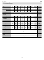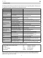
1
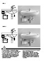
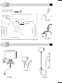
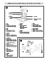
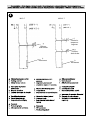
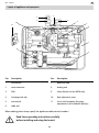
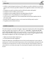
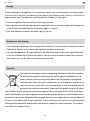
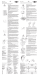
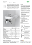
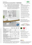
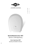
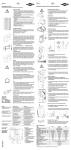
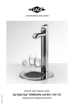
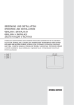
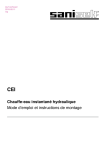
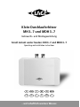
Klein-Durchlauferhitzer
MH 3..7 und MDH 3..7
Gebrauchs- und Montageanleitung
Small instant water heaters MH 3..7 and MDH 3..7
Operating and installation instructions
D
GB
F
NL
PL
RUS
CZ
SK
S
N
FIN
P
...wirtschaftlich warmes Wasser.
1
Spezial-Strahlregler (M22/24)
einsetzen (liegt dem Gerät bei)
Ø 50
Elektroanschluss mit
Netzleitung (ggf. kürzen)
3/8“
M../ ENM
G 3/8
Eckventil Abgang G 3/8
17
187
≥ 70
ca. 297
75
Maßangaben in mm
Waschbeckenoberkante ca. 850
140
Eckventil ca. 550
Kabeleingang ca. 570
Achse Befestigung ca. 520
Elektro-Anschlussdose ca. 660
132
Kabeleingang
3/8”
M../ SNM
2
M.. / BG
M.. / SMB
M.. / BGS
a.
Temperaturerhöhung t1-t2 in K
3
3.5 kW 4.4 kW 5.7 kW 6.5 kW
40
30
20
10
1.2
1 .4
1 .7
2 .0
2 .5
3 .0
Warmwasserleistung l/min
b.
4
5
3 .5
4 .0
6
7
8
MDH 3..7
MH 3..7
i.
Sicherheitstemperaturbegrenzer
g.
Differenzdruckschalter
g.
Differenzdruckschalter
h.
Heizelement
7
h.
Heizelement
MH 3..7, MDH 3..7
Inhaltsverzeichnis · Table of contents · Index
D
GB
F
NL
PL
RUS
CZ
SK
S
N
FIN
P
3
GB
MH 3..7, MDH 3..7
Layout of appliance and spareparts
1
3
2
2
10
4
11
5
6
7
9
8
Pos.
Description
Pos.
Description
1
wall bracket
7
appliance hood
2
water connector
8
heating wire
3
filter
9
safety thermal cut-out (MDH only)
4
fastening earth clip
10
flow adjustment screw
5
microswitch
11
6
cable seal
set of small spareparts (for spare
requirements, not included in delivery)
When ordering, please always specify the appliance model and serial number!
Read these operating instructions carefully
before installing and using the heater!
11
GB
MH 3..7, MDH 3..7
Safety notes:
• Installation, commissioning and maintenance of this appliance may only be undertaken by an authorized
technician who will then be responsible for adherence to the applicable standards and installation regulations.
• The appliance may only be used when correctly installed and in perfect working order!
• The appliance must be installed in a frost-free room!
• The appliance must be completely filled with water before being switched on!
• The appliance and its wiring and piping must not be modified in any way!
• The front cover of the appliance must never be opened before disconnecting the appliance from the
mains power supply!
• Be careful! When the appliance has been in use for some time, the fittings may be very hot!
• The appliance must be earthed at all times!
Intended use, operation
This small instantaneous water heater shall supply a single outlet and shall only be used for heating drinking
water with a specific water resistance of ≥ 800 Ω cm at 15 °C. Types MH 3..7 may be used only with
special safety taps (open outlet)! Use for any other purpose is not permitted. When the hot water tap is
open, the heater switches on automatically and heats the water as it passes through the appliance. The hot
water temperature depends on the flow rate (see diagram, fig.3). For this reason:
• slightly close the tap for higher temperatures or
• mix with cold water for lower temperatures.
Varying inlet temperatures and available pressure may affect the outlet temperature. In winter, when the
incoming water is cold, the desired outlet temperature can often be achieved only by reducing the flow rate.
If the flow rate or the water pressure is too low, or if the hot water tap is closed, the heater switches off
automatically. For a satisfactory water output, the enclosed special jet regulator and/or hand shower shall
be used.
12
GB
MH 3..7, MDH 3..7
Purging
To prevent damage to the appliance, the instantaneous water heater must be purged for air before using it
for the first time. Each time it is emptied (e.g. after work on the plumbing system, if there is a risk of frost or
following repair work), the appliance must be purged for air before it is used again.
1 Disconnect appliance from the mains by disactivating the fuses.
2 Next, open and close the hot water tap valve several times until no more air emerges from the pipe and
all air has been eliminated from the water heater (approx. 1 minute).
3 Only then should you reconnect the power supply to the unit.
Maintenance and cleaning
• Clean the heater and the taps only by wiping with a damp cloth. Do not use abrasive cleaners or solvents.
• Clean the jet regulator or the hand-shower regularly and replace as necessary.
• Dirt and scale deposited in the pipes and heater will affect the function of the heater. Typical indications
of this are a reduced rate of flow or noisy flow. In such cases, have the heater inspected by a technician
and, if necessary, have the filter in the cold-water inlet cleaned.
Recycling
This symbol on the products and/or accompanying documents means that used electrical and electronic products should not be mixed with general household waste. For
proper treatment, recovery and recycling, please take these products to designated
collection points where they will be accepted on a free of charge basis. Alternatively, in
some countries you may be able to return your products to your local retailer upon the
purchase of an equivalent new product. Disposing of this product correctly will help to
save valuable resources and prevent any potential negative effects on human health and the environment
which could otherwise arise from inappropriate waste handling. Please contact your local authority for further details of your nearest designated collection point. Penalties may be applicable for incorrect disposal of
this waste, in accordance with national legislation. If you are a business user and you wish to discard electrical and electronic equipment, please contact your dealer or supplier for further information. This symbol is
only valid in the European Union.
13
GB
MH 3..7, MDH 3..7
The following must be observed:
The heater is installed as shown in the immediate vicinity of the outlet in a frost-free room. We guarantee
trouble-free operation only if CLAGE fittings and accessories are used. Note the following during installation:
• Observe the statutory regulations of the respective country, as well as those
of the local electricity and water supply companies.
• Check technical data and the information on the rating plate.
• Ensure that all accessories are removed from the packing materials.
• Easy access to the appliance shall be guaranteed at all times.
An external shut-off valve has to be installed.
• Thoroughly rinse the water pipes before connection.
• Install types MH 3..7 only with special safety taps (open-outlet tap)!
• Optimum operation is ensured at a water flow pressure of 0.2 to 0.4 MPa (2-4 bar),
avoiding pressures exceeding 1 MPa (10 bar).
Installing the appliance
• Secure the wall bracket to the wall with screws and suitable wall plugs (see fig 4).
Wall bracket is not necessary for M/SMB and M/BG.
• Place the appliance on the wall bracket (see fig. 5).
• The appliance is good for undersink and oversink installation according to the examples of installation
(see fig. 1+2). For undersink installation the water connectors must point vertically upwards, for oversink
installation the water connectors must point vertically downwards.
• Pipe connection (see fig. 6):
Cold water inlet (blue) and hot water outlet (red) are marked by coloured round points on the rating
plate. Connect the colour marked tap pipes to the water inlet/outlet accordingly.
Avoid any kind of mechanical pressure exerted on the appliance, e.g. by water pipes etc.
• After installation, check all connections for leaks.
In order to obtain an optimum water jet at low flow rates, always screw the enclosed jet regulator onto the
tap outlet. This insert fits commercially available sleeves with an M22 or M24 thread.
14
GB
MH 3..7, MDH 3..7
Electrical connection
Fill the appliance completely with water by repeatedly opening and closing the tap before
connecting to electrical power. The heating element may be damaged if this is not done!
• The installation must comply with current IEC regulations or national local regulations or any particular
regulations, specified by the local electricity supply company!
• The mains cable must be permanently connected via connecting box as shown in the circuit diagram.
(see fig. 8). The earth conductor must be connected.
• A circuit breaker in accordance with IEC with a contact opening gap of at least 3 mm for each pole must
be provided on the mains side of the connecting box.
• The wiring cross-section must be well adapted to the corresponding power rating. See technical data.
• To protect the appliance, a fuse element must be fitted with a tripping current commensurate with the
nominal current of the appliance.
Putting into service
Do not switch on the electric power at this time!
1. Open the hot-water tap and allow water to flow
until it emerges free of air bubbles.
2. Now close the circuit breaker. Hot water is delivered.
• Explain the functions of the heater to the user and ensure
that he knows how to use it.
• Hand over these operating instructions to the user.
Adjusting the water flow
The temperature and the flow depend on the conditions at the installation site. In case of quite low or high
inlet temperatures, you may reduce or increase the flow at the flow adjustment to achieve the desired hot
water temperature (see fig. 7 how to adjust the screw).
Careful! Don’t turn the adjustment screw further than the indent mark in order to avoid water
leakage.
15
GB
MH 3..7, MDH 3..7
Technical specifications
Type
MH 3
MDH 3
MH 4
MDH 4
MH 6
MDH 6
MH 7
MDH 7
0.1
0.1
0.1
0.1
0.1
0.1
0.1
0.1
l
open outlet
• / 0 (0)
–
• / 0 (0)
–
• / 0 (0)
–
• / 0 (0)
–
MPa (bar)
closed outlet
–
•/1(10)
–
•/1(10)
–
•/1(10)
–
•/1(10)
MPa (bar)
Capacity
system
heating system
IES system: bare resistance element
required water
resistance
≥ 800 Ω cm at 15 ° C
electric supply
Ω cm
230 ~
230 ~
230 ~
230 ~
230 ~
230 ~
400 2~
400 2~
V
nom. power rating
@ 230/400V
3.5
3.5
4.4
4.4
5.7
5.7
6.5
6.5
kW
nominal current
15.2
15.2
19.1
19.1
24.8
24.8
16.2
16.2
A
req. min. cross-section
1.5
1.5
2.5
2.5
2.5
2.5
2.5
2.5
mm2
hot water output
at ∆t = 25 K
2.0
2.0
2.5
2.5
3.3
3.3
3.7
3.7
l / min
switching off @
1.2
1.2
1.4
1.4
1.7
1.7
2.0
2.0
l / min
weight filled with
water approx.
1.2
1.3
1.2
1.3
1.2
1.3
1.2
1.3
kg
dimensions (H x W x D)
13.2 x 18.7 x 8.0
protection class acc.
to VDE
1
type of protection acc.
to VDE
approval marks
IP 25: oversink units / IP 24: undersink units
see rating plate
16
cm
GB
MH 3..7, MDH 3..7
Customer service
The following table will help you to determine and rectify the reasons for possible problems. Maintenance of
this appliance may only be undertaken by an authorized technician!
Fault
Cause
Action
no water flows
water supply is turned off
open the main water valve / the shut-off valve
the jet regulator is not fitted
fit the special CLAGE jet regulator
water flows more slowlythan expected
the heater switches itself
on and off
water remains cold,
although the appliance
switches on
appliance does not
switch and the water
remains cold
hot water temperature
varies
hot water temperature
too low
water pressure is not sufficient
check the water flow pressure
dirt in the pipes
remove any dirt from the filter, valves and/or taps
check the technical data
water pressure is varying
flow rate is too low
remove any dirt / increase the flow water pressure
close other taps
open the shut-off valve further
faulty heating element
replace heating element (by authorized technician)
one phase is not connected
check the supply voltage (2/PE 400 V - MH/MDH 7
only)
electric supply incorrect
check the electric supply
circuit breaker has tripped
safety thermal cut-out has tripped
have the fault rectified by a technician and reset the
safety thermal cut-out / circuit breaker
water connections mixed up
check installation
water pressure is not sufficient
adjust the water flow (see fig. 7)
open the shut-off valve
dirt in the pipes
remove dirt from the inlet and outlet pipes
water pressure varies
stabilise the water flow pressure
avoid using other taps in the same circuit
(i.e. toilets, washing machines)
supply voltage varies
check the supply voltage
flow rate is too high
inlet temperature is too low
adjust the flow either at the tap, the valve or the
flow adjustment screw
power supply is too low
measure the temperatures and flow rate and compare
with the technical data, check the power supply
If you cannot rectify the fault with the aid of this table, please contact:
CLAGE GmbH Central customer service
Fon:
+49 (0) 41 31 - 89 01-40
Pirolweg 1 – 5
Fax:
+49 (0) 41 31 - 89 01-41
D - 21337 Lüneburg
E-Mail:
service @ clage.de
Deutschland
Internet:
www.clage.com
We can either give you the name and address of an authorised customer service company or repair the
heater ourselves. In the latter case, please send in the heater (at your cost and risk) with details of the
problem and a copy of the sales invoice.
17
CLAGE GmbH
Pirolweg 1– 5
21337 Lüneburg
Fon: +49 (0) 41 31 - 89 01-0
Fax: +49 (0) 41 31 - 83 200
E-Mail: info @ clage.de
Internet: www.clage.de
CLAGE GmbH Zentralkundendienst
Fon: +49 (0) 41 31 - 89 01-40
Fax: +49 (0) 41 31 - 89 01-41
service @ clage.de
Technische Änderungen und Irrtum vorbehalten. 9120-1401 12-05 GP-BA 60
E-Mail: