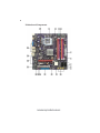
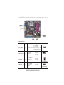
1
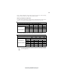
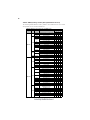
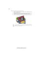
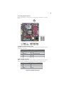
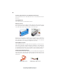
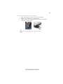
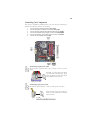
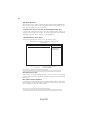
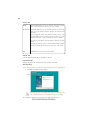
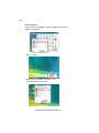
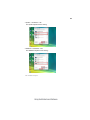
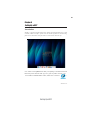
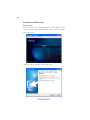
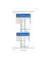
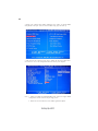
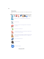
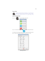
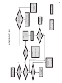
Preface
Copyright
This publication, including all photographs, illustrations and software, is protected
under international copyright laws, with all rights reserved. Neither this manual, nor
any of the material contained herein, may be reproduced without written consent of
the author.
Version 2.0
Disclaimer
The information in this document is subject to change without notice. The manufacturer makes no representations or warranties with respect to the contents hereof and
specifically disclaims any implied warranties of merchantability or fitness for any
particular purpose. The manufacturer reserves the right to revise this publication and
to make changes from time to time in the content hereof without obligation of the
manufacturer to notify any person of such revision or changes.
Trademark Recognition
Microsoft, MS-DOS and Windows are registered trademarks of Microsoft Corp.
MMX, Pentium, Pentium-II, Pentium-III, Celeron are registered trademarks of Intel
Corporation.
Other product names used in this manual are the properties of their respective
owners and are acknowledged.
Federal Communications Commission (FCC)
This equipment has been tested and found to comply with the limits for a Class B
digital device, pursuant to Part 15 of the FCC Rules. These limits are designed to
provide reasonable protection against harmful interference in a residential installation. This equipment generates, uses, and can radiate radio frequency energy and, if
not installed and used in accordance with the instructions, may cause harmful interference to radio communications. However, there is no guarantee that interference
will not occur in a particular installation. If this equipment does cause harmful
interference to radio or television reception, which can be determined by turning the
equipment off and on, the user is encouraged to try to correct the interference by one
or more of the following measures:
•
•
•
•
Reorient or relocate the receiving antenna
Increase the separation between the equipment and the receiver
Connect the equipment onto an outlet on a circuit different from that to
which the receiver is connected
Consult the dealer or an experienced radio/TV technician for help
Shielded interconnect cables and a shielded AC power cable must be employed with
this equipment to ensure compliance with the pertinent RF emission limits governing
this device. Changes or modifications not expressly approved by the system’s manufacturer could void the user’s authority to operate the equipment.
Preface
ii
Declaration of Conformity
This device complies with part 15 of the FCC rules. Operation is subject to the
following conditions:
•
•
This device may not cause harmful interference, and
This device must accept any interference received, including interference that may cause undesired operation
Canadian Department of Communications
This class B digital apparatus meets all requirements of the Canadian Interferencecausing Equipment Regulations.
Cet appareil numérique de la classe B respecte toutes les exigences du Réglement sur
le matériel brouilieur du Canada.
About the Manual
The manual consists of the following:
Describes features of the
motherboard.
Chapter 1
Introducing the Motherboard
Go to
Chapter 2
H
page 1
Describes installation of
motherboard components.
Installing the Motherboard
Go to
H
page 7
Provides information on using the BIOS Setup Utility.
Chapter 3
Using BIOS
Go to
Chapter 4
Using the Motherboard Software
page 27
Describes the motherboard
software
Go to
Chapter 5
H
H
page 43
Describes the eJIFFY
setting up
Go to
H page 51
Setting Up eJIFFY
Provides basic trouble shooting tips
Chapter 6
Trouble Shooting
Go to
Preface
H
page 61
iii
TABLE OF CONTENTS
Preface
i
Chapter 1
1
Introducing the Motherboard
1
Introduction......................................................................................1
Feature...............................................................................................2
Motherboard Components.............................................................4
Chapter 2
7
Installing the Motherboard
7
Safety Precautions...........................................................................7
Choosing a Computer Case............................................................7
Installing the Motherboard in a Case...........................................7
Checking Jumper Settings..............................................................8
Setting Jumpers.........................................................................8
Checking Jumper Settings.........................................................9
Jumper Settings.........................................................................9
Installing Hardware........................................................................10
Installing the Processor...........................................................10
Installing Memory Modules.....................................................12
Expansion Slots......................................................................15
Connecting Optional Devices..................................................17
Installing a Hard Disk Drive/CD-ROM/SATA Hard Drive.....20
Connecting I/O Devices................................................................22
Connecting Case Components.....................................................23
Front Panel Header.................................................................25
Chapter 3
27
Using BIOS
27
About the Setup Utility................................................................ 27
The Standard Configuration....................................................27
Entering the Setup Utility.........................................................27
Using BIOS.....................................................................................28
Standard CMOS Setup............................................................29
Advanced Setup.......................................................................31
Advanced Chipset Setup..........................................................33
iv
Integrated Peripherals.............................................................34
Power Management Setup.......................................................35
PCI/PnP Configuration............................................................36
PC Health Status......................................................................37
Frequency/Voltage Control......................................................39
Load Default Settings...............................................................40
Supervisor Password...............................................................40
User Password.........................................................................41
Save & Exit Setup.....................................................................41
Exit Without Saving..................................................................41
Updating the BIOS...................................................................42
Chapter 4
43
Using the Motherboard Software
43
About the Software CD-ROM/DVD-ROM..................................43
Auto-installing under Windows XP/Vista/7...............................43
Running Setup....................................................................44
Manual Installation........................................................................46
Utility Software Reference............................................................46
Chapter 5
51
Setting Up eJIFFY
51
Introduction....................................................................................51
Installation and BIOS Setup.........................................................52
Entering eJIFFY........................................................................................55
Features Icons.........................................................................................56
Usage FAQ..............................................................................................57
Chapter 6
61
Trouble Shooting
61
Start up problems during assembly..................................................61
Start up problems after prolong use................................................62
Maintenance and care tips................................................................62
Basic Troubleshooting Flowchart...................................................63
1
Chapter 1
Introducing the Motherboard
Introduction
Thank you for choosing the G43T-M motherboard. This motherboard is a high
performance, enhanced function motherboard designed to support the LGA775 socket
Intel® Yorkfield/Wolfdale family processors for high-end business or personal desktop markets.
The motherboard incorporates the G43 Northbridge (NB) and ICH10 Southbridge
(SB) chipsets. The Northbridge supports a Front Side Bus (FSB) frequency of 1333/
1066/800 MHz using a scalable FSB Vcc_CPU. The memory controller supports
DDR2 memory DIMM frequencies of 800/667. It supports four DDR2 Sockets with
up to maximum memory of 8 GB*. DDR2 Maximum memory bandwidth of 12.8 GB/
s in dual-channel symmetric mode assuming DDR2 800 MHz. High resolution graphics via one PCI Express slot, intended for Graphics Interface, is fully compliant to
the PCI Express Base Specification revision 2.0.
The ICH10 Southbridge supports one PCI slot which is PCI v2.3 compliant. In
addition, two PCI Express x1 slots are supported. It implements an EHCI compliant
interface that provides 480 Mb/s bandwidth for 12 USB 2.0 ports (6 USB ports and 3
USB 2.0 headers support additional 6 USB ports). The Southbridge integrates a Serial
ATA host controller, supporting six SATA ports with maximum transfer rate up to
3.0 Gb/s each.
The motherboard is equipped with advanced full set of I/O ports in the rear panel,
including PS/2 mouse and keyboard connectors, one HDMI port, one VGA port, six
USB ports, one LAN port and audio jacks for microphone, line-in and 8-ch line-out.
* You can only insert two Single Bank memory modules to each channel
when using one channel with two dimms, since G43 only supports two
dimms with Dual-channel.
Introducing the Motherboard
2
Feature
Processor
The motherboard uses an LGA775 type of Intel ® Yorkfield/Wolfdale family
processors that carries the following features:
•
•
•
Accommodates Intel® Yorkfield/Wolfdale family processors
Supports a system bus (FSB) of 1333/1066/800 MHz
Supports “Hyper-Threading” technology CPU
“Hyper-Threading” technology enables the operating system into thinking it’s
hooked up to two processors, allowing two threads to be run in parallel, both on
separate “logical” processors within the same physical processor.
Chipset
The G43 Northbridge (NB) and ICH10 Southbridge (SB) chipsets are based on an
innovative and scalable architecture with proven reliability and performance.
•
G43
(NB)
•
•
•
•
ICH10
(SB)
•
•
•
•
•
•
Supports 36-bit host bus addressing, allowing the CPU to
access the entire 64 GB of the memory address space
2 GB/s point-to-point Direct Media Interface (DMI) to ICH10
(1 GB/s each direction)
Supports 512-Mb and 1-Gb DDR2 and 512-Mb, 1-Gb, and
2-Gb DDR3 technologies for x8 and x16 devices
One, 16-lane (x16) PCI Express port intended for supporting up to two external PCI Express graphics card in bifurcated mode, fully compatible to the PCI Express Base Specification revision 2.0
An integrated graphics device (IGD) delivering cost competitive 3D, 2D and video capabilities
Enhanced DMA Controller, Timer/Counter functions, and Interrupt Controller
Compliant with PCI Express Base Specification, Revision
1.1
Compliant with PCI v2.3 specification
Integrated SATA 3.0 Gb/s Host Controller
Integrated USB 2.0 Host Controller supporting up to twelve
USB 2.0 ports
Integrated Gigabit LAN Controller
Memory
•
•
•
Supports DDR2 800/667 DDR2 SDRAM with Dual-channel architecture
Accommodates four unbuffered DIMMs
Up to 2 GB per DIMM with maximum memory size up to 8 GB*
* You can only insert two Single Bank memory modules to each channel
when using one channel with two dimms, since G43 only supports two
dimms with Dual-channel.
Introducing the Motherboard
3
Audio
•
•
•
•
•
8 Channel High Definition Audio Codec
All DACs support 192K/96K/48K/44.1KHz DAC sample rate
High-quality analog differential CD input
Meets Microsoft WLP 3.08 audio requirements
Direct Sound 3DTM compatible
Onboard LAN
•
Integrated 10/100/1000 Mbps IEEE 802.3 compliant
Expansion Options
The motherboard comes with the following expansion options:
•
•
•
•
•
One PCI Express x 16 slot for Graphic Interface
Two PCI Express x1 Slots
One 32-bit PCI v2.3 compliant slot•
One IDE connector supporting up to two IDE devices
Six 7-pin SATA connectors
This motherboard supports Ultra DMA bus mastering with transfer rates of 133/
100/66/33 Mb/s.
Integrated I/O
The motherboard has a full set of I/O ports and connectors:
•
Two PS/2 ports for mouse and keyboard
•
One HDMI port
•
One VGA port
•
Six USB ports
•
One LAN port
•
Audio jacks for microphone, line-in and 8-ch High Definition Audio
output
BIOS Firmware
This motherboard uses AMI BIOS that enables users to configure many system
features including the following:
•
Power management
•
Wake-up alarms
•
CPU parameters
•
CPU and memory timing
The firmware can also be used to set parameters for different processor clock
speeds.
1. Some hardware specifications and software items are subject to change
without prior notice.
2. Due to chipset limitation, we recommend that motherboard be operated in the ambiance between 0 and 50 ° C.
Introducing the Motherboard
4
Motherboard Components
Introducing the Motherboard
5
Table of Motherboard Components
LABEL
1. CPU Socket
2. CPU_FAN
3. COM
4. DDR2_DIMM1~4
5. ATX_POWER
6. SYS_FAN
7. SATA1~6
8. USBPWR_F1~2
9. F_PANEL
10. F_USB1~3
11. SPK
12. CLR_CMOS
13. IDE
14. SPDIFO
15. F_AUDIO
16. CD_IN
17. PCI
18. PCIE1~2
19. PCIEX16
20. USBPWR_R1~2
21. ATX12V
COMPONENTS
LGA775 socket for Intel® Yorkfield/Wolfdale CPUs
CPU cooling fan connector
Onboard Serial Port header
240-pin DDR2 SDRAM slots
Standard 24-pin ATX power connector
System cooling fan connector
Serial ATA connectors
Front Panel USB Power Select jumpers
Front panel switch/LED header
Front Panel USB headers
Internal Speaker header
Clear CMOS jumper
Primary IDE connector
SPDIF out header
Front panel audio header
Analog audio input connector
32-bit add-on card slot
PCI Express x1 slots
PCI Express x16 graphics card slot
Rear USB/PS2 Power Select jumpers
4-pin +12V power connector
This concludes Chapter 1. The next chapter explains how to install the motherboard.
Introducing the Motherboard
6
Memo
Introducing the Motherboard
7
Chapter 2
Installing the Motherboard
Safety Precautions
•
•
•
•
•
Follow these safety precautions when installing the motherboard
Wear a grounding strap attached to a grounded device to avoid damage from static electricity
Discharge static electricity by touching the metal case of a safely
grounded object before working on the motherboard
Leave components in the static-proof bags they came in
Hold all circuit boards by the edges. Do not bend circuit boards
Choosing a Computer Case
There are many types of computer cases on the market. The motherboard complies
with the specifications for the Micro ATX system case. First, some features on the
motherboard are implemented by cabling connectors on the motherboard to indicators and switches on the system case. Make sure that your case supports all the
features required. Secondly, this motherboard supports two enhanced IDE drives.
Make sure that your case has sufficient power and space for all drives that you intend
to install.
Most cases have a choice of I/O templates in the rear panel. Make sure that the I/O
template in the case matches the I/O ports installed on the rear edge of the
motherboard.
This motherboard carries a Micro ATX form factor of 244 x 244 mm. Choose a case
that accommodates this form factor.
Installing the Motherboard in a Case
Refer to the following illustration and instructions for installing the motherboard in
a case.
Most system cases have mounting brackets installed in the case, which correspond
the holes in the motherboard. Place the motherboard over the mounting brackets
and secure the motherboard onto the mounting brackets with screws.
Ensure that your case has an I/O template that supports the I/O ports and expansion
slots on your motherboard.
Installing the Motherboard
8
Do not over-tighten the screws as this can stress the motherboard.
Checking Jumper Settings
This section explains how to set jumpers for correct configuration of the motherboard.
Setting Jumpers
Use the motherboard jumpers to set system configuration options. Jumpers with
more than one pin are numbered. When setting the jumpers, ensure that the jumper
caps are placed on the correct pins.
The illustrations show a 2-pin jumper. When
the jumper cap is placed on both pins, the
jumper is SHORT. If you remove the jumper
cap, or place the jumper cap on just one pin,
the jumper is OPEN.
SHORT
This illustration shows a 3-pin jumper. Pins
1 and 2 are SHORT.
Installing the Motherboard
OPEN
9
Checking Jumper Settings
The following illustration shows the location of the motherboard jumpers. Pin 1 is
labeled.
Jumper Settings
Jumper
CLR_CMOS
Type
Description
3-pin CLEAR CMOS
Setting (default)
1-2: NORMAL
2-3: CLEAR
Before clearing the
1
CMOS, make sure to
turn the system off. CLR_CMOS
Front Panel
USBPWR_F1~2 3-pin USB Power
Select Jumper
1-2: VCC
2-3: 5VSB
Rear USB/PS2
USBPWR_R1 3-pin Power Select
Jumper
1-2: VCC
2-3: 5VSB
1
USBPWR_F1~2
1
USBPWR_R1
Rear USB/PS2
USBPWR_R2 3-pin Power Select
Jumper
1-2: VCC
2-3: 5VSB
Installing the Motherboard
1
USBPWR_R2
10
1. To avoid the system instability after clearing CMOS, we recommend
users to enter the main BIOS setting page to “Load Default Settings”
and then “Save & Exit Setup”.
2. Make sure the power supply provides enough 5VSB voltage before selecting the 5VSB function.
3. It is required that users place the USBPWR_F1~2 & USBPWR_R1~2
cap onto 2-3 pin rather than 1-2 pin as default if you want to wake up
the computer by USB/PS2 KB/Mouse.
Installing Hardware
Installing the Processor
Caution: When installing a CPU heatsink and cooling fan make sure
that you DO NOT scratch the motherboard or any of the surfacemount resistors with the clip of the cooling fan. If the clip of the
cooling fan scrapes across the motherboard, you may cause serious
damage to the motherboard or its components.
On most motherboards, there are small surface-mount resistors near
the processor socket, which may be damaged if the cooling fan is
carelessly installed.
Avoid using cooling fans with sharp edges on the fan casing and the
clips. Also, install the cooling fan in a well-lit work area so that you
can clearly see the motherboard and processor socket.
Before installing the Processor
This motherboard automatically determines the CPU clock frequency and system
bus frequency for the processor. You may be able to change the settings in the system
Setup Utility. We strongly recommend that you do not over-clock processors or
other components to run faster than their rated speed.
Warning:
1. Over-clocking components can adversely affect the reliability of
the system and introduce errors into your system. Over-clocking can
permanently damage the motherboard by generating excess heat in
components that are run beyond the rated limits.
2. Always remove the AC power by unplugging the power cord from
the power outlet before installing or removing the motherboard or
other hardware components.
This motherboard has an LGA775 socket. When choosing a processor, consider the
performance requirements of the system. Performance is based on the processor
design, the clock speed and system bus frequency of the processor, and the quantity
of internal cache memory and external cache memory.
Installing the Motherboard
11
CPU Installation Procedure
The following illustration shows CPU installation components.
A. Read and follow the instructions shown on the
sticker on the CPU cap.
B. Unload the cap
· Use thumb & forefinger to hold the
lifting tab of the cap.
· Lift the cap up and remove the cap
completely from the socket.
C. Open the load plate
· Use thumb & forefinger to hold the
hook of the lever, pushing down and pulling
aside unlock it.
· Lift up the lever.
· Use thumb to open the load plate. Be
careful not to touch the contacts.
D. Install the CPU on the socket
· Orientate CPU package to the socket.
Make sure you match triangle marker
to pin 1 location.
E. Close the load plate
· Slightly push down the load plate onto the
tongue side, and hook the lever.
· CPU is locked completely.
F. Apply thermal grease on top of the CPU.
G.
Fasten the cooling fan supporting base onto
the CPU socket on the motherboard.
H. Make sure the CPU fan is plugged to the
CPU fan connector. Please refer to the CPU
cooling fan user’s manual for more detail
installation procedure.
1. To achieve better airflow rates and heat dissipation, we suggest that you
use a high quality fan with 3800 rpm at least. CPU fan and heatsink
installation procedures may vary with the type of CPU fan/heatsink sup
plied. The form and size of fan/heatsink may also vary.
2. DO NOT remove the CPU cap from the socket before installing a CPU.
3. Return Material Authorization (RMA) requests will be accepted only if
the motherboard comes with the cap on the LGA775 socket.
Installing the Motherboard
12
Installing Memory Modules
This motherboard accommodates four memory modules. It can support four 240-pin
DDR2 800/667. The total memory capacity is 8 GB*.
DDR2 SDRAM memory module table
Memory module
Memory Bus
DDR2 667
DDR2 800
333 MHz
400 MHz
You must install at least one module in any of the four slots. Each module can be
installed with 4 GB of memory; total memory capacity is 8 GB*.
Do not remove any memory module from its antistatic packaging
until you are ready to install it on the motherboard. Handle the
modules only by their edges. Do not touch the components or metal
parts. Always wear a grounding strap when you handle the modules.
Installation Procedure
Refer to the following to install the memory modules.
1
2
3
4
5
6
This motherboard supports unbuffered DDR2 SDRAM .
Push the latches on each side of the DIMM slot down.
Align the memory module with the slot. The DIMM slots are keyed with
notches and the DIMMs are keyed with cutouts so that they can only be
installed correctly.
Check that the cutouts on the DIMM module edge connector match the
notches in the DIMM slot.
Install the DIMM module into the slot and press it firmly down until it
seats correctly. The slot latches are levered upwards and latch on to
the edges of the DIMM.
Install any remaining DIMM modules.
* You can only insert two Single Bank memory modules to each channel
when using one channel with two dimms, since G43 only supports two
dimms with Dual-channel.
Installing the Motherboard
13
Due to chipset limitation, please follow closely the table below when installing
memory for dual channel or single channel mode operation.
Memory Installation Combination
For dual channel configuration, you must always install identical (the same board,
speed, size and chip-type) DDR2 DIMM pair in the slots of the same color.
Mem ory Installation Com bination -- Dual Channel Mode
DS => Double Side, SS => Single Side, X => None Installed Mem ory
Com bination for
Dual Channel Mode
DIMM1
DIMM2
DIMM3
2 Module
DS/SS
X
DS/SS
DIMM4
X
2 Module
DS/SS
X
X
DS/SS
2 Module
X
DS/SS
DS/SS
X
2 Module
X
DS/SS
X
DS/SS
4 Module
SS
SS
SS
SS
The following combination will result in single channel mode operation:
Mem ory Installation Com bination -- Single Channel Mode
DS => Double Side, SS => Single Side, X => None Installed Mem ory
DIMM1
Com bination for
Single Channel Mode
DIMM2
DIMM3
DIMM4
DS/SS - Insert into any DIMM slot
1 Module
2 Module
DS/SS
X
X
2 Module
X
DS/SS
X
X
2 Module
X
X
DS/SS
X
DS/SS
X
2 Module
X
X
X
2 Module
SS
SS
X
X
2 Module
X
X
SS
SS
To enable successful system boot-up, always insert the memory modules
into the DIMM1 first.
Installing the Motherboard
14
Table A: DDR2 (memory module) QVL (Qualified Vendor List)
The following DDR2 800/667 memory modules and combination have been tested
and qualified for use with this motherboard.
DIMM Slot: DS-Double side, SS-Single Side, 0-No DIMM socket
Type
Size
256 MB
512 MB
DDR2 667
Vendor
Module Nam e
Infineon
HYS64T325001HU-3-A HYB18T256
0
SS
0
SS
0
SS
0
Apacer
78.91G92.9K5
SS
SS
SS
SS
VALUESELECT 32M8CEC
DS
0
DS
0
CORSAIR
64M8CFE PS1000545
SS
0
SS
0
Corsair K4T5108QC
SS
0
SS
0
GEIL
GL2L64M088BA18W
SS
0
SS
0
Ramaxel
5LB31 D9DCL
SS
0
0
0
Samsung
K4T51083QC
SS
0
SS
0
Apacer
Infineon
E5108AB-5C-E
SS
0
0
0
JetRam J12Q3AB-6
SS
0
SS
0
SEL520ZCE6
SS
0
SS
0
TMM6208G8M30B
0
SS
0
SS
Elpida 1GB AM4B5708GEWS7E-0637F
DS
0
DS
0
AM4B5708GQJS7E0631F
0
DS
0
DS
HYB18T512800BF3S
DS
0
0
0
Aeneon AET93E30RB-0650 1GB
DS
0
DS
0
LeadMax
LeadMax LD5PS1G831
DS
0
DS
0
A-DATA
AD29608A8A-25EG
SS
0
SS
0
Elpida
E5108AJBG-8E-E
HYS64T64020HU-2.5-A HYB18T256
800AF25
0
Infineon
SS
0
SS
DS
0
DS
0
Infinity
04751208CZ5U2D
SS
0
SS
0
Kingston
KHX6400D2ULK2
SS
0
SS
0
Micron
6WD22 D9GKX
SS
0
SS
0
Sync MAX
U538H8G09DHL
SS
0
SS
0
A-DATA
VD29608A8D-25EG-E0722
DS
0
0
0
AM4B5808CQJS8E 0749D
SS
0
SS
0
AM4B5708JQJS8E 0749D
SS
0
SS
0
AM4B5708BPJS8E0634E
DS
0
DS
0
CM2X1024-6400PRO
DS
0
0
0
CM2X1024-6400
DS
0
DS
0
0
Apacer
CORSAIR
GEIL
Hexon
GL2L64M088BA18H
DS
0
DS
GEIL PLATINUM EDITION
DS
0
DS
0
NP18T648512F-2.5
DS
0
DS
0
0
Infinity
04701G16CZ5U2G
DS
0
DS
Ramaxel
E5108AHSE-8E-E 0705098L1
DS
0
DS
0
Samsung
ZCE7 K4T510830E
DS
0
DS
0
Transcend
TQ123PGF8T0709
DS
0
DS
0
UMAX
U2S12D30TP-8E
RED FEROCIOUS DRAGON
M2OMI6H3J4720L1C5Z
DS
0
DS
0
DS
0
DS
0
Aeneon
AET03R25DC 0732
DS
0
DS
0
Apacer
AM4B5808CQJS8E 0747D
DS
0
DS
0
CORSAIR
CM2X2048-6400C5
DS
0
DS
0
Micron
7QEIID9HNP
DS
0
DS
0
PSC
A3R1GE3CFF 734MAAOE
DS
0
DS
0
Qimonda
HYB18T1G800C2F-25F 0744
DS
0
DS
0
Samsung
HCF7 K4T1G084QQ
0
0
DS
0
A-DATA
2 GB
SS
5NB31 D9DCG
1 GB
1 GB
4
0
AD29608A88-3EG
Tw inmos
DDR2 800
3
SS
A-DATA
Transcend
512 MB
2
0
Ramaxel
Sync MAX
2 GB
DIMM Slot
1
SS
Installing the Motherboard
15
Expansion Slots
Installing Add-on Cards
The slots on this motherboard are designed to hold expansion cards and connect
them to the system bus. Expansion slots are a means of adding or enhancing the
motherboard’s features and capabilities. With these efficient facilities, you can
increase the motherboard’s capabilities by adding hardware that performs tasks that
are not part of the basic system.
PCIEX16 Slot
The PCI Express x16 slot is used to install an external PCI Express
graphics card that is fully compliant to the PCI Express Base Specification revision 2.0.
PCIE1~2 Slots The PCI Express x1 slots are fully compliant to the PCI Express
Base Specification revision 1.1.
PCI Slot
This motherboard is equipped with one standard PCI slot. PCI
stands for Peripheral Component Interconnect and is a bus standard for expansion cards, which for the most part, is a supplement
of the older ISA bus standard. The PCI slot on this board is PCI v2.3
compliant.
Before installing an add-on card, check the documentation for the card
carefully. If the card is not Plug and Play, you may have to manually
configure the card before installation.
Installing the Motherboard
16
Follow these instructions to install an add-on card:
1
2
3
Remove a blanking plate from the system case corresponding to the
slot you are going to use.
Install the edge connector of the add-on card into the expansion slot.
Ensure that the edge connector is correctly seated in the slot.
Secure the metal bracket of the card to the system case with a screw.
For some add-on cards, for example graphics adapters and network
adapters, you have to install drivers and software before you can
begin using the add-on card.
Installing the Motherboard
17
Connecting Optional Devices
Refer to the following for information on connecting the motherboard’s optional
devices:
F_AUDIO: Front Panel Audio header
This header allows the user to install auxiliary front-oriented microphone and lineout ports for easier access.
Pin
1
3
5
7
9
Signal Name
Pin
Signal Name
PORT 1L
2
AUD_GND
PORT 1R
4
PRESENCE#
PORT 2R
6
SENSE1_RETURN
SENSE_SEND
8
10
KEY
PORT 2L
SENSE2_RETURN
SPDIFO: SPDIF out header
This is an optional header that provides an S/PDIF (Sony/Philips Digital Interface)
output to digital multimedia device through optical fiber or coaxial connector.
Pin
1
2
3
4
Signal Name
Function
SPDIF
SPDIF digital output
+5VA
5V analog Power
Key
No pin
GND
Ground
Installing the Motherboard
18
SATA1~6: Serial ATA connectors
These connectors are use to support the new Serial ATA devices for the highest date
transfer rates (3.0 Gb/s), simpler disk drive cabling and easier PC assembly. It eliminates limitations of the current Parallel ATA interface. But maintains register compatibility and software compatibility with Parallel ATA.
Pin
1
3
5
7
Signal Name
Pin
2
4
6
-
Ground
TXRXGround
Signal Name
TX+
Ground
RX+
-
F_USB1~3: Front Panel USB headers
The motherboard has six USB ports installed on the rear edge I/O port array. Additionally, some computer cases have USB ports at the front of the case. If you have
this kind of case, use auxiliary USB connector to connect the front-mounted ports to
the motherboard.
Pin
Signal Name
Function
1
USBPWR
2
3
4
5
6
7
8
9
10
USBPWR
Front Panel USB Power
USB_FP_P0-
USB Port 0 Negative Signal
USB_FP_P1-
USB Port 1 Negative Signal
Front Panel USB Power
USB_FP_P0+
USB Port 0 Positive Signal
USB_FP_P1+
USB Port 1 Positive Signal
GND
GND
Ground
Ground
Key
No pin
USB_FP_OC0
Overcurrent signal
Please make sure that the USB cable has the same pin assignment as
indicated above. A different pin assignment may cause damage or system
hang-up.
CD_IN: Analog Audio Input connector
Pin
1
2
3
4
Signal Name
Function
CD_L
CD In left channel
GND
Ground
GND
CD_R
Ground
CD In right channel
Installing the Motherboard
19
COM: Onboard Serial Port header
Connect a serial port extension bracket to this header to add a second serial port to
your system.
Pin
1
2
3
4
5
6
7
8
9
10
Signal Name
DCDB
SINB
SOUTB
Function
Data Carrier Detect
Serial Input
UART B Serial Output
DTRB
UART B Data Terminal Ready
GND
Ground
DSRB
Data Set Ready
RTSB
CTSB
RART B Request to Send
Clear to Send
RI
Key
Ring Indicator
No pin
SPI_ROM: SPI ROM header
This 8 Mb ROM contains the programmable BIOS program.
Pin
Signal Name
1
2
3
4
5
6
7
CHIP SELECT
8
Function
Select chip
VCC
VCC
DATA OUTPUT
data output
HOLD
hold
WRITE PROTECT
BIOS write protect
CLOCK
clock
CND
CND
DATA INPUT
data input
Installing the Motherboard
20
Installing a Hard Disk Drive/CD-ROM/SATA Hard Drive
This section describes how to install IDE devices such as a hard disk drive and a CDROM drive.
About IDE Devices
Your motherboard has one IDE channel interface.
IDE: IDE Connector
This motherboard supports six high data transfer SATA ports with each runs up to 3.0
Gb/s. To get better system performance, we recommend users connect the CD-ROM
to the IDE channel, and set up the hard dives on the SATA ports.
IDE devices enclose jumpers or switches used to set the IDE device as MASTER or
SLAVE. Refer to the IDE device user’s manual. Installing two IDE devices on one
cable, ensure that one device is set to MASTER and the other device is set to SLAVE.
The documentation of your IDE device explains how to do this.
About SATA Connectors
Your motherboard features six SATA connectors supporting a total of six drives.
SATA refers to Serial ATA (Advanced Technology Attachment) is the standard interface for the IDE hard drives which are currently used in most PCs. These connectors
are well designed and will only fit in one orientation. Locate the SATA connectors on
the motherboard and follow the illustration below to install the SATA hard drives.
Installing Serial ATA Hard Drives
To install the Serial ATA (SATA) hard drives, use the SATA cable that supports the
Serial ATA protocol. This SATA cable comes with an SATA power cable. You can
connect either end of the SATA cable to the SATA hard drive or the connector on the
motherboard.
SATA cable
(optional)
SATA power cable
Installing the Motherboard
(optional)
21
Refer to the illustration below for proper installation:
1
2
3
Attach either cable end to the connector on the motherboard.
Attach the other cable end to the SATA hard drive.
Attach the SATA power cable to the SATA hard drive and connect the
other end to the power supply.
This motherboard supports the “Hot-Plug” function.
Installing the Motherboard
22
Connecting I/O Devices
The backplane of the motherboard has the following I/O ports:
PS2 Mouse
Use the upper PS/2 port to connect a PS/2 pointing device.
PS2 Keyboard
Use the lower PS/2 port to connect a PS/2 keyboard.
VGA Port
Connect your monitor to the VGA port.
HDMI Port
Connect the HDMI port to the HDMI devices.
USB Ports
Use the USB ports to connect USB devices.
LAN Port
Connect an RJ-45 jack to the LAN port to connect your
computer to the network.
Audio Ports
Use the audio jacks to connect audio devices. The D port is
for stereo line-in signal, while the F port is for microphone
in signal. This motherboard supports 8-channel audio devices that correspond to the A,B, C, and E port respectively. In addition, all of the 3 ports, B, C, and E provide
users with both right & left channels individually. Users
please refer to the following note for specific port function
definition.
A : Center & Woofer
D : Line-in
B : Back Surround
E : Front Out
C : Side Surround
F : Mic_in Rear
The above port definition can be changed to audio input or
audio output by changing the driver utility setting.
Installing the Motherboard
23
Connecting Case Components
After you have installed the motherboard into a case, you can begin connecting the
motherboard components. Refer to the following:
1
2
3
4
5
6
Connect the CPU cooling fan cable to CPU_FAN.
Connect the system cooling fan connector to SYS_FAN.
Connect the case switches and indicator LEDs to the F_PANEL.
Connect the standard power supply connector to ATX_POWER.
Connect the auxiliary case power supply connector to ATX12V.
Connec the case speaker cable to SPK.
Connecting 24-pin power cable
The ATX 24-pin connector allows you to connect to ATX v2.x power
supply.
With ATX v2.x power supply, users please
note that when installing 24-pin power
cable, the latches of power cable and the
ATX_POWER match perfectly.
24-pin power cable
Connecting 4-pin power cable
The ATX12V power connector is used to provide power to the CPU.
When installing 4-pin power cable, the
latches of power cable and the ATX12V
match perfectly.
4-pin power cable
Installing the Motherboard
24
CPU_FANS/SYS_FAN: FAN Power Connector
Pin
1
2
3
4
Signal Name
GND
+12V
Sense
PWM
Function
System Ground
Power +12V
Sensor
PWM
Users please note that the fan connector supports the CPU cooling fan
of 1.1A ~ 2.2A (26.4W max) at +12V.
ATX_ POWER: ATX 24-pin Power Connector
Pin
Signal Name
1
2
3
4
5
6
7
8
9
+3.3V
10
11
12
+12V
Pin
13
14
15
16
17
18
19
20
21
+3.3V
Ground
+5V
Ground
+5V
Ground
PWRGD
+5VSB
22
23
24
+12V
+3.3V
Signal Name
+3.3V
-12V
Ground
PS_ON
Ground
Ground
Ground
-5V
+5V
+5V
+5V
Ground
ATX12V: ATX 12V Power Connector
Pin
1
2
3
4
Signal Name
Ground
Ground
+12V
+12V
SPK: Internal speaker header
Pin
1
2
3
4
Signal Name
VCC
Key
GND
Signal
Installing the Motherboard
25
Front Panel Header
The front panel header (F_PANEL) provides a standard set of switch and LED
headers commonly found on ATX or Micro ATX cases. Refer to the table below for
information:
Pin
1
Signal
Function
Pin
HD_LED_P Hard disk LED(+)
2
Signal
Function
FP PWR/SLP *MSG LED(+)
3
HD_LED_N Hard disk LED(- )
4
FP PWR/SLP *MSG LED(-)
5
RST_SW_N Reset Switch(-)
6
PWR_SW_P Power Switch(+)
7
RST_SW_P
Reset Switch(+)
8
PWR_SW_N Power Switch(-)
9
RSVD
Reserved
10 Key
No pin
* MSG LED (dual color or single color)
Hard Drive Activity LED
Connecting pins 1 and 3 to a front panel mounted LED provides visual indication
that data is being read from or written to the hard drive. For the LED to function
properly, an IDE drive should be connected to the onboard IDE interface. The LED
will also show activity for devices connected to the SCSI (hard drive activity LED)
connector.
Power/Sleep/Message waiting LED
Connecting pins 2 and 4 to a single or dual-color, front panel mounted LED provides
power on/off, sleep, and message waiting indication.
Reset Switch
Supporting the reset function requires connecting pins 5 and 7 to a momentarycontact switch that is normally open. When the switch is closed, the board resets and
runs POST.
Power Switch
Supporting the power on/off function requires connecting pins 6 and 8 to a momentary-contact switch that is normally open. The switch should maintain contact for at
least 50 ms to signal the power supply to switch on or off. The time requirement is
due to internal de-bounce circuitry. After receiving a power on/off signal, at least two
seconds elapses before the power supply recognizes another on/off signal.
This concludes Chapter 2. The next chapter covers the BIOS.
Installing the Motherboard
26
Memo
Installing the Motherboard
27
Chapter 3
Using BIOS
About the Setup Utility
The computer uses the latest “American Megatrends Inc.” BIOS with support for
Windows Plug and Play. The CMOS chip on the motherboard contains the ROM
setup instructions for configuring the motherboard BIOS.
The BIOS (Basic Input and Output System) Setup Utility displays the system ’ s
configuration status and provides you with options to set system parameters. The
parameters are stored in battery-backed-up CMOS RAM that saves this information
when the power is turned off. When the system is turned back on, the system is
configured with the values you stored in CMOS.
The BIOS Setup Utility enables you to configure:
•
•
•
•
Hard drives, diskette drives and peripherals
Video display type and display options
Password protection from unauthorized use
Power Management features
The settings made in the Setup Utility affect how the computer performs. Before
using the Setup Utility, ensure that you understand the Setup Utility options.
This chapter provides explanations for Setup Utility options.
The Standard Configuration
A standard configuration has already been set in the Setup Utility. However, we
recommend that you read this chapter in case you need to make any changes in the
future.
This Setup Utility should be used:
•
•
•
•
•
when changing the system configuration
when a configuration error is detected and you are prompted to make
changes to the Setup Utility
when trying to resolve IRQ conflicts
when making changes to the Power Management configuration
when changing the password or making other changes to the Security
Setup
Entering the Setup Utility
When you power on the system, BIOS enters the Power-On Self Test (POST)
routines. POST is a series of built-in diagnostics performed by the BIOS. After the
POST routines are completed, the following message appears:
Press DEL to enter SETUP
Using BIOS
28
Press the delete key to access the BIOS Setup Utility.
CMOS Setup Utility -- Copyright (C) 1985-2008, American Megatrends, Inc.
f Standard CMOS Setup
f Advanced Setup
f Advanced Chipset Setup
f Integrated Peripherals
f Power Management Setup
f PCI/PnP Configuration
f PC Health Status
fFrequency/Voltage Control
Load Default Settings
fSupervisor Password
fUser Password
Save & Exit Setup
Exit Without Saving
mnlk : Move
Enter : Select +/-/: Value F10: Save
F1:General Help
F9: Load Default Settings
ESC: Exit
v02.61 (C)Copyright 1985-2008, American Mega trends, Inc.
Using BIOS
When you start the Setup Utility, the main menu appears. The main menu of the
Setup Utility displays a list of the options that are available. A highlight indicates
which option is currently selected. Use the cursor arrow keys to move the highlight
to other options. When an option is highlighted, execute the option by pressing
<Enter>.
Some options lead to pop-up dialog boxes that prompt you to verify that you wish to
execute that option. Other options lead to dialog boxes that prompt you for information.
Some options (marked with a triangle f) lead to submenus that enable you to change
the values for the option. Use the cursor arrow keys to scroll through the items in the
submenu.
In this manual, default values are enclosed in parenthesis. Submenu items are denoted
by a triangle f .
The default BIOS setting for this motherboard applies for most conditions
with optimum performance. It is not suggested to change the default
values in the BIOS setup and the manufacture takes no responsibility to
any damage caused by changing the BIOS settings.
BIOS Navigation Keys
The BIOS navigation keys are listed below:
KEY
ESC
FUNCTION
Exits the current menu
mnlk
Scrolls through the items on a menu
+/-/PU/PD
Enter
Modifies the selected field’s values
Select
F9
Loads an optimized setting for better performance
F10
Saves the current configuration and exits setup
F1
Displays a screen that describes all key functions
Using BIOS
29
For the purpose of better product maintenance, the manufacture reserves
the right to change the BIOS items presented in this manual. The BIOS setup
screens shown in this chapter are for reference only and may differ from the
actual BIOS. Please visit the manufacture’s website for updated manual.
Standard CMOS Setup
This option displays basic information about your system.
CMOS Setup Utility - Copyright (C) 1985-2008, American Megatrends, Inc.
Standard CMOS Setup
Date (www mm:dd:yy)
Time (hh:mm:ss)
Mon 04/28/2008
05 : 30 : 04
f
f
f
f
f
f
f
f
Not Detected
Not Detected
Not Detected
Not Detected
Not Detected
Not Detected
Not Detected
Not Detected
SATA1
SATA2
SATA3
SATA4
SATA5
SATA6
PATA MASTER
PATA SLAVE
IDE BusMaster
Help Item
User [Enter], [TAB]
or [SHIFT-TAB] to
select a field.
Use [+] or [-] to
configure system Date.
Enabled
mnlk: Move
Enter : Select +/-/: Value F10: Save ESC: Exit
F1: General Help
F9: Load Default Settings
Date (www mm:dd:yy) & Time (hh:mm:ss)
The Date and Time items show the current date and time on the computer. If you are
running a Windows OS, these items are automatically updated whenever you make
changes to the Windows Date and Time Properties utility.
f SATA 1~6/PATA MASTER/SLAVE
Your computer has one IDE channel which can be installed with one or two devices
(Master and Slave). In addition, this motherboard supports six SATA channels and
each channel allows one SATA device to be installed. Use these items to configure
each device on the IDE channel.
CMOS SETUP UTILITY - Copyright (C) 1985-2008, American Megatrends, Inc.
SATA1
SATA1
Device :
Help Item
Not Detected
Type
LBA/Large Mode
Block (Multi-Sector Transfer
PIO Mode
DMA Mode
S.M.A.R.T
32Bit Data Transfer
Auto
Auto
Auto
Auto
Auto
Auto
Enabled
mnlk: Move
Select the type
of device connected
to the system.
Enter : Select +/-/: Value F10: Save ESC: Exit
F1: General Help
F9: Load Default Settings
Using BIOS
30
Type (Auto)
Use this item to configure the type of the IDE device that you specify. If the feature
is enabled, it will enhance hard disk performance by reading or writing more data
during each transfer.
LBA/Large Mode (Auto)
Use this item to set the LAB/Large mode to enhance hard disk performance by
optimizing the area the hard disk is visited each time.
Block (Multi-Sector Transfer) (Auto)
If the feature is enabled, it will enhance hard disk performance by reading or writing
more data during each transfer.
PIO Mode (Auto)
Use this item to set the PIO mode to enhance hard disk performance by optimizing
the hard disk timing.
DMA Mode (Auto)
DMA capability allows user to improve the transfer-speed and data-integrity for
compatible IDE devices.
S.M.A.R.T. (Auto)
The S.M.A.R.T. (Self-Monitoring, Analysis and Reporting Technology) system is a
diagnostics technology that monitors and predicts device performance. S.M.A.R.T.
software resides on both the disk drive and the host computer.
32Bit Data Transfer (Enabled)
Use this item to enable or disable 32Bit Data Transfer.
Press <Esc> to return to the Standard CMOS Setup page.
IDE BusMaster (Enabled)
This item enables or disables the DMA under DOS mode. We recommend you to leave
this item at the default value.
Press <Esc> to return to the main menu setting page.
Using BIOS
31
Advanced Setup
This page sets up more advanced information about your system. Handle this page
with caution. Any changes can affect the operation of your computer.
CMOS Setup Utility - Copyright (C) 1985-2008, American Megatrends, Inc.
Advanced Setup
Thermal Management
TM Status
Limit CPUID MaxVal
Enhanced Halt (C1E)
Intel XD Bit
Intel EIST
Intel Virtualization Technol
Quick Power on Self Test
Boot Up Numlock Status
APIC Mode
1st Boot Device
2nd Boot Device
3rd Boot Device
f Hard Disk Drives
Boot Other Device
ECS eJIFFY Function
Enabled
TM1/TM2
Disabled
Enabled
Disabled
Enabled
Enabled
Enabled
On
Enabled
Hard Disk Drive
CD/DVD
Removable Dev.
Press Enter
Yes
Disabled
Help Item
For the processor its
CPUTD belows 0F14h.
TM2 only can be enable
under below settings.
1.Freq.>=3.6GHz FSB800
2.Freq.>=2.8GHz FSB533
mnlk: Move
Enter : Select +/-/: Value F10: Save ESC: Exit
F1: General Help
F9: Load Default Settings
Thermal Management (Enabled/TM1/TM2)
This item displays CPU’s temperature and enables you to set a safe temperature to
Prescott CPU.
Limit CPUID MaxVal (Disabled)
This item can support Prescott CPUs for old OS. Users please note that under NT
4.0, it must be set “Enabled”, while under WinXP, it must be set “Disabled”.
Enhanced Halt (C1E) (Enabled)
This item enables or disables enhanced halt (C1E).
Intel XD Bit (Disabled)
This item allows users to enable or disable the Intel XD bit.
Intel EIST (Enabled)
This item allows users to enable or disable the EIST (Enhanced Intel SpeedStep
technology.
Intel Virtualization Technol (Enabled)
Hardware Virtualization Technology enables processor feature for runningmultiple
simultaneous Virtual Machines allowing specialized softwareapplications to run in full
isolation of each other.
Quick Power on Self Test (Enabled)
Enable this item to shorten the power on testing (POST) and have your system start
up faster. You might like to enable this item after you are confident that your system
hardware is operating smoothly.
Boot Up Numlock Status (On)
This item defines if the keyboard Num Lock key is active when your system is
started.
Using BIOS
32
APIC Mode (Enabled)
This item allows you to enable or disable the APCI (Advanced Programmable Interrupt Controller) mode. APIC provides symmetric multi-processing (SMP) for systems, allowing support for up to 60 processors.
1st/2nd/3rd Boot Device (Hard Disk Drive/CD/DVD/Removable Dev.)
Use this item to determine the device order the computer used to look for an
operating system to load at start-up time. The devices showed here will be different
depending on the exact devices installed on your motherboard.
fHard Disk Drives (Press Enter)
Scroll to this item and press <Enter> to view the following screen:
CMOS Setup Utility - Copyright (C) 1985-2008, American Megatrends, Inc.
Hard Disk Drives
Help Item
Hard Disk Drives
1st Drive
MAXTOR 6L060J3
Specifies the boot
sequence from the
available devices.
mnlk: Move
Enter : Select +/-/: Value F10: Save ESC: Exit
F1: General Help
F9: Load Default Settings
Press <Esc> to return to the Advanced Setup page.
Boot Other Device (Yes)
When enabled, the system searches all other possible locations for an operating
system if it fails to find one in the devices specified under the First, Second and Third
boot devices.
ECS eJIFFY Function (Disabled)
Use this item to enable or disable the ECS eJIFFY Function. eJIFFY is ECS unique
software program for the quick access to the internet without entering O.S. Please
refer to Chapter 5 to know more about eJIFFY.
Press <Esc> to return to the main menu setting page.
Using BIOS
33
Advanced Chipset Setup
This page sets up more advanced information about your system. Handle this page
with caution. Any changes can affect the operation of your computer.
CMOS Setup Utility - Copyright (C) 1985-2008, American Megatrends, Inc.
Advanced Chipset Setup
DRAM Frequency
Configure DRAM Timing by SPD
Pre-allocated share mem
DVMT Memory
Memory Remap Feature
HPET
Auto
Enabled
64MB
256MB
Enabled
Enabled
Help Item
Options
Auto
667 MHz
800 MHz
mnlk: Move
Enter : Select +/-/: Value F10: Save ESC: Exit
F1: General Help
F9: Load Default Settings
DRAM Frequency (Auto)
This item enables users to adjust the DRAM frequency. The default setting is auto and
we recommend users leave the setting unchanged. Modify it at will may cause the
system to be unstable.
Configure DRAM Timing by SPD (Enabled)
When this item is set to enable, the DDR timing is configured using SPD. SPD (Serial
Presence Detect) is located on the memory modules, BIOS reads information coded
in SPD during system boot up.
Pre-allocated share mem (64MB)
This item is used to choose the pre-allocated Graphics VGA memory size when IGD
(Internal Graphics Device) is enabled.
DVMT Memory (256MB)
When set to Fixed Mode, the graphics driver will reserve a fixed portion of the
system memory as graphics memory, according to system and graphics requirements.
Memory Remap Feature (Enabled)
This item allows you to remap the overlapped PCI memory above the total physical
memory if you have a 64 bit OS and 8 GB of RAM.
HPET (Enabled)
This item enables or disables HPET (High Precision Event Timer) support.
Press <Esc> to return to the main menu setting page.
Using BIOS
34
Integrated Peripherals
This page sets up some parameters for peripheral devices connected to the system.
CMOS Setup Utility - Copyright (C) 1985-2008, American Megatrends, Inc.
Integrated Peripherals
Onboard SATA Mode
Onboard LAN Function
Onboard LAN Boot ROM
Onboard AUDIO Function
Serial Port1 Address
USB Functions
Legacy USB Support
On Chip SATA2 Controller
Enhanced
Enabled
Disabled
Enabled
3F8&IRQ4
Enabled
Enabled
Enabled
Help Item
Options
Disabled
Compatible
Enhanced
mnlk: Move
Enter : Select +/-/: Value F10: Save ESC: Exit
F1: General Help
F9: Load Default Settings
Onboard SATA Mode (Enhanced)
Use this item to select the mode of the Serial ATA.
OnBoard LAN Function (Enabled)
Use this item to enable or disable the onboard LAN function.
OnBoard LAN Boot ROM (Disabled)
Use this item to enable or disable the booting from the onboard LAN or a network
add-in card with a remote boot ROM installed.
OnBoard AUDIO Function (Enabled)
Use this item to enable or disable the onboard Audio function.
Serial Port1 Address (3F8/IRQ4)
Use this item to enable or disable the onboard COM1 serial port, and to assign a port
address.
USB Functions (Enabled)
Use this item to enable or disable the USB function.
Legacy USB Support (Enabled)
Use this item to enable or disable support for legacy USB devices. Setting to Auto
allows the system to detect the presence of USB device at startup. If detected, the
USB controller legacy mode is enabled. If no USB device is detected, the legacy USB
support is disabled.
On Chip SATA2 Controller (Enabled)
This item allows you to enable or disable the on chip SATA2 controller.
Press <Esc> to return to the main menu setting page.
Using BIOS
35
Power Management Setup
This page sets up some parameters for system power management operation.
CMOS Setup Utility - Copyright (C) 1985-2008, American Megatrends, Inc.
Power Management Setup
ACPI Suspend Type
Soft-off by PWR-BTTN
PWRON After PWR-Fail
Resume by Ring
Resume by PCI/ PCI-E/Lan PME
Resume by USB (S3)
Resume By PS2 KB (S3)
Resume By PS2 MS (S3)
Resume on RTC Alarm
S3 (STR)
Instant Off
Power Off
Disabled
Disabled
Disabled
Disabled
Disabled
Disabled
Help Item
Select the ACPI
state used for
System Suspend.
mnlk: Move
Enter : Select +/-/: Value F10: Save ESC: Exit
F1: General Help
F9: Load Default Settings
ACPI Suspend Type (S3(STR))
Use this item to define how your system suspends. In the default, S3, the suspend
mode is a suspend to RAM, i.e, the system shuts down with the exception of a refresh
current to the system memory.
Soft-Off By PWR-BTTN (Instant Off)
Under ACPI (Advanced Configuration and Power management Interface) you can
create a software power down. In a software power down, the system can be resumed
by Wake Up Alarms. This item lets you install a software power down that is controlled by the power button on your system. If the item is set to Instant-Off, then the
power button causes a software power down. If the item is set to Delay 4 Sec, then
you have to hold the power button down for four seconds to cause a software power
down.
PWRON After PWR-Fail (Power Off)
This item enables your computer to automatically restart or return to its operating
status.
Resume by Ring (Disabled)
An input signal on the serial Ring Indicator (RI) line (in other words, an incoming
callon the modem) awakens the system from a soft off state.
Resume by PCI/PCI-E/Lan PME (Disabled)
These items specify whether the system will be awakened from power saving
modeswhen activity or input signal of the specified hardware peripheral or component isdetected.
Resume by USB (S3) (Disabled)
This item allows users to enable or disable the USB device Walk-up from S3 mode.
Resume By PS2 KB (S3) (Disabled)
Use this item to allow keyboard activity to awaken the system from power saving
mode.
Using BIOS
36
Resume By PS2 MS (S3) (Disabled)
This item enables or disables you to allow mouse activity to awaken the system from
power saving mode.
Resume on RTC Alarm (Disabled)
The system can be turned off with a software command. If you enable this item, the
system can automatically resume at a fixed time based on the system’s RTC (realtime
clock). Use the items below this one to set the date and time of the wake-up alarm.
You must use an ATX power supply in order to use this feature.
Press <Esc> to return to the main menu setting page.
PCI / PnP Configuration
This page sets up some parameters for devices installed on the PCI bus and those
utilizing the system plug and play capability.
CMOS Setup Utility - Copyright (C) 1985-2008, American Megatrends, Inc.
PCI / PnP Configuration
Init Display First
PCI
Help Item
Select which graphics
controller to use as
the primary boot
device.
mnlk: Move
Enter : Select +/-/: Value F10: Save ESC: Exit
F1: General Help
F9: Load Default Settings
Init Display First (PCI)
Use this item to select which graphics controller to use as the primary boot devices.
Press <Esc> to return to the main menu setting page.
Using BIOS
37
PC Health Status
On motherboards support hardware monitoring, this item lets you monitor the
parameters for critical voltages, temperatures and fan speeds.
CMOS Setup Utility - Copyright (C) 1985-2008, American Megatrends, Inc.
PC Health Status
-=- System Hardware Monitor-=Press Enter
f Smart Fan Function
Shutdown Temperature
Disabled
CPU Temperature
: 31°C/87°F
System Temperature
: 22°C/71°F
CPU FAN Speed
: 3770 RPM
SYS FAN Speed
: N/A
CPU Core
: 1.248V
VDIMM
: 1.920V
Help Item
mnlk: Move
Enter : Select +/-/: Value F10: Save ESC: Exit
F1: General Help
F9: Load Default Settings
f Smart Fan Function
Scroll to this item and press <Enter> to view the following screen:
CMOS Setup Utility - Copyright (C) 1985-2008, American Megatrends, Inc.
Smart Fan Function
CPU SMART FAN Control
SYS SMART FAN Control
Disabled
Disabled
Help Item
Options
Disabled
Enabled
mnlk: Move
Enter : Select +/-/: Value F10: Save ESC: Exit
F1: General Help
F9: Load Default Settings
CPU/SYS SMART FAN Control (Disabled)
These items enable you to define the CPU/System temperatur by smartly adjusting
the CPU/System fan. When it is set at certain temperature, the CPU/SYS Fan PWM
value will change accordingly.
Using BIOS
38
ECS supports the latest PECI host technology. While using Wolfdale or
Yorkfield CPU, the original images of the BIOS item “PC Health Status”
and “Smart FAN Function” will be replaced by PECI mode and negative
number. (The max data from PECI is zero.)
CMOS Setup Utility - Copyright (C) 1985-2008, American Megatrends, Inc.
PC Health Status
Help Item
Hardware Health Event Monitoring
f Smart Fan Function
Press Enter
33°C/91°F
2537 RPM
0 RPM
1.280V
1.840V
System Temperature
CPU Fan Speed:
SYS FAN Speed:
CPU Vcore:
VDIMM:
-=- PECI Mode-=Offset to TCC Activation Temp.:
-20
mnlk: Move
Enter : Select +/-/: Value F10: Save ESC: Exit
F1: General Help
F9: Load Default Settings
CMOS Setup Utility - Copyright (C) 1985-2008, American Megatrends, Inc.
Smart Fan Function
SMART Fan Control
SMART Fan start PWM value
SMART Fan start Offset (-)
CPU DeltaT
Fan1 Slope PWM value/1 Unit
Fan1 Full Speed Offset (-)
SMART Fan2 Control
Enabled
28
30
+3
5
10
Disabled
mnlk: Move
Help Item
Options
Disabled
Enabled
Enter : Select +/-/: Value F10: Save ESC: Exit
F1: General Help
F9: Load Default Settings
Press <Esc> to return to the PC Health Status page.
Using BIOS
39
Shutdown Temperature (Disabled)
Enable you to set the maximum temperature the system can reach before powering
down.
System Component Characteristics
These items display the monitoring of the overall inboard hardware health events,
such as System & CPU temperature, CPU & DIMM voltage, CPU & system fan
speed,...etc.
•
CPU/System Temperature
•
CPU/SYS FAN Speed
•
CPU Core
•
VDIMM
Press <Esc> to return to the main menu setting page.
Frequency/Voltage Control
This page enables you to set the clock speed and system bus for your system. The
clock speed and system bus are determined by the kind of processor you have installed in your system.
CMOS Setup Utility - Copyright (C) 1985-2008, American Megatrends, Inc.
Frequency/Voltage Control
Manufacturer : Intel
Ratio Actual Value: 9
CPU Frequency Setting :
CPU Over-clocking Func.:
Auto Detect DIMM/PCI CIK
Spread Spectrum
Memory Voltage
Help Item
333MHz
Disabled
Enabled
Enabled
1.90V
Options
Disabled
Enabled
mnlk: Move
Enter : Select +/-/: Value F10: Save ESC: Exit
F1: General Help
F9: Load Default Settings
Manufacturer (Intel)
This item displays the information of current manufacturer of the CPU installed in
your computor.
Ratio Actual Value (9)
These items show the locked ratio status and the actual ratio of the CPU installed in
your System.
CPU Frequency Setting (333MHz)
This item indicates the current CPU frequency. Users can not make any change to
this item. Please noted that the frequency will be varied with different CPU.
Using BIOS
40
CPU Over-clocking Func. (Disabled)
This item decides the CPU over-clocking function/frequencyinstalled in your system. If the over-clocking fails, please turn offthe system power. And then, hold the
PageUp key (similar to theClear CMOS function) and turn on the power, the BIOS
willrecover the safe default.
Auto Detect DIMM/PCI Clk (Enabled)
When this item is enabled, BIOS will disable the clock signal of free DIMM/PCI slots.
Spread Spectrum (Enabled)
If you enable spread spectrum, it can significantly reduce the EMI (Electro-Magnetic
Interference) generated by the system.
Memory Voltage (1.90V)
This item allows users to adjust the DDR memory voltage.
Press <Esc> to return to the main menu setting page.
Load Default Settings
This option opens a dialog box to ask if you are sure to install optimized defaults or
not. You select [OK], and then <Enter>, the Setup Utility loads all default values; or
select [Cancel], and then <Enter>, the Setup Utility does not load default values.
Supervisor Password
This page helps you install or change a password.
CMOS Setup Utility - Copyright (C) 1985-2008, American Megatrends, Inc.
Supervisor Password
Supervisor Password
:Not Installed
Change Supervisor Password
Press Enter
Help I
tem
Install or Change the
password.
mnlk: Move
Enter : Select +/-/: Value F10: Save ESC: Exit
F1: General Help
F9: Load Default Settings
Supervisor Password (Not Installed)
This item indicates whether a supervisor password has been set. If the password has
been installed, Installed displays. If not, Not Installed displays.
Change Supervisor Password (Press Enter)
You can select this option and press <Enter> to access the sub menu. You can use the
sub menu to change the supervisor password.
Press <Esc> to return to the main menu setting page.
Using BIOS
41
User Password
This page helps you install or change a password.
CMOS Setup Utility - Copyright (C) 1985-2008, American Megatrends, Inc.
User Password
User Password
: Not Installed
Change User Password
Help item
Press Enter
Install or Change the
password.
mnlk: Move
Enter : Select +/-/: Value F10: Save ESC: Exit
F1: General Help
F9: Load Default Settings
User Password (Not Installed)
This item indicates whether a user password has been set. If the password has been
installed, Installed displays. If not, Not Installed displays.
Change User Password (Press Enter)
You can select this option and press <Enter> to access the sub menu. You can use the
sub menu to change the user password. This item will show if Supervisor Password is
set.
Press <Esc> to return to the main menu setting page.
Save & Exit Setup
Highlight this item and press <Enter> to save the changes that you have made in the
Setup Utility and exit the Setup Utility. When the Save and Exit dialog box appears,
select [OK] to save and exit, or select [Cancel] to return to the main menu.
Exit Without Saving
Highlight this item and press <Enter> to discard any changes that you have made in
the Setup Utility and exit the Setup Utility. When the Exit Without Saving dialog box
appears, select [OK] to discard changes and exit, or select [Cancel] to return to the
main menu.
If you have made settings that you do not want to save, use the “Exit
Without Saving” item and select [OK] to discard any changes you have
made.
Using BIOS
42
Updating the BIOS
You can download and install updated BIOS for this motherboard from the
manufacturer’s Web site. New BIOS provides support for new peripherals, improvements in performance, or fixes for known bugs. Install new BIOS as follows:
1
2
3
4
5
6
7
If your motherboard has a BIOS protection jumper, change the setting to
allow BIOS flashing.
If your motherboard has an item called Firmware Write Protect in Advanced BIOS features, disable it. (Firmware Write Protect prevents
BIOS from being overwritten.)
Create a bootable system disk. (Refer to Windows online help for
information on creating a bootable system disk.)
Download the Flash Utility and new BIOS file from the manufacturer’s
Web site. Copy these files to the bootable device.
Turn off your computer and insert the bootable device in your computer. (You might need to run the Setup Utility and change the boot
priority items on the Advanced BIOS Features Setup page, to force
your computer to boot from the bootable device first.)
At the C:\ or A:\ prompt, type the Flash Utility program name and the file
name of the new bios and then press <Enter>. Example: AMINF340.EXE
040706.ROM
When the installation is complete, remove the bootable device from the
computer and restart your computer. If your motherboard has a Flash
BIOS jumper, reset the jumper to protect the newly installed BIOS from
being overwritten. The computer will restart automatically.
This concludes Chapter 3. Refer to the next chapter for information on the software
supplied with the motherboard.
Using BIOS
43
Chapter 4
Using the Motherboard Software
About the Software CD-ROM/DVD-ROM
The support software CD-ROM/DVD-ROM that is included in the motherboard package contains all the drivers and utility programs needed to properly run the bundled
products. Below you can find a brief description of each software program, and the
location for your motherboard version. More information on some programs is
available in a README file, located in the same directory as the software. Before
installing any software, always inspect the folder for files named README.TXT or
something similar. These files may contain important information that is not
included in this manual.
1. Never try to install all software from folder that is not specified for use with
your motherboard.
2. The notice of Intel HD audio installation (optional): The Intel High Definition audio functionality unexpectedly quits working in Windows Server
2003 Service Pack 1 or Windows XP Professional x64 Edition. Users need
to download and install the update packages from the Microsoft Download
Center “before” installing HD audio driver bundled in the Driver disk.
Please log on to http://support.microsoft.com/default.aspx?scid=kb;enus;901105#appliesto for more information.
Auto-installing under Windows XP/Vista/7
The Auto-install CD-ROM/DVD-ROM makes it easy for you to install the drivers and
software for your motherboard.
If the Auto-install CD-ROM/DVD-ROM does not work on your system,
you can still install drivers through the file manager for your OS (for
example, Windows Explorer). Refer to the Utility Folder Installation Notes
later in this chapter.
The support software CD-ROM/DVD-ROM disc loads automatically under Windows
XP/Vista/7. When you insert the CD-ROM/DVD-ROM disc in the CD-ROM/DVDROM drive, the autorun feature will automatically bring up the install screen. The
screen has three buttons on it, Setup, Browse CD and Exit.
If the opening screen does not appear; double-click the file “setup.exe”
in the root directory.
Using the Motherboard Software
44
Drivers Tab
Setup
Click the Setup button to run the software installation program.
Select from the menu which software you want to install.
Browse CD The Browse CD button is the standard Windows command that
allows you to open Windows Explorer and show the contents of the
support disk.
Before installing the software from Windows Explorer, look for a file
named README.TXT or something similar. This file may contain
important information to help you install the software correctly.
Some software is installed in separate folders for different operating
systems.
In installing the software, execute a file named SETUP.EXE by doubleclicking the file and then following the instructions on the screen.
Exit
The EXIT button closes the Auto Setup window.
Utilities Tab
Lists the software utilities that are available on the disk.
Information Tab
Displays the path for all software and drivers available on the disk.
Running Setup
Follow these instructions to install device drivers and software for the motherboard:
1.
Click Setup. The installation program begins:
The following screens are examples only. The screens and driver lists
will be different according to the motherboard you are installing.
The motherboard identification is located in the upper left-hand corner.
Using the Motherboard Software
45
2.
Click Next. The following screen appears:
3.
Check the box next to the items you want to install. The default options are recommended.
4.
Click Next run the Installation Wizard. An item installation screen appears:
5.
Follow the instructions on the screen to install the items.
Drivers and software are automatically installed in sequence. Follow the
onscreen instructions, confirm commands and allow the computer to
restart a few times to complete the installation.
Using the Motherboard Software
46
Windows Vista/7 will appear below UAC (User Account Control) message
after the system restart. You must select “Allow” to install the next driver.
Continue this process to complete the drivers installation.
Manual Installation
Insert the disk in the CD-ROM/DVD-ROM drive and locate the PATH.DOC file in
the root directory. This file contains the information needed to locate the drivers for
your motherboard.
Look for the chipset and motherboard model; then browse to the directory and path
to begin installing the drivers. Most drivers have a setup program (SETUP.EXE) that
automatically detects your operating system before installation. Other drivers have
the setup program located in the operating system subfolder.
If the driver you want to install does not have a setup program, browse to the
operating system subfolder and locate the readme text file (README.TXT or
README.DOC) for information on installing the driver or software for your operating system.
Utility Software Reference
All the utility software available from this page is Windows compliant. They are
provided only for the convenience of the customer. The following software is furnished under license and may only be used or copied in accordance with the terms of
the license.
These software(s) are subject to change at anytime without prior no tice.
Please refer to the support disk for available software.
Using the Motherboard Software
47
HDMI Audio setting SOP
OS: XP system
1. Control Panel-->Sound and Audio Device Properties
2. a. Audio--> Sound playback--> Default device--> HD Auido Output
b. Audio--> Sound playback--> Default device--> HDMI Auido Output
3. a. User Playback Audio speaker function working
b. User Playback HDMI speaker function working
Using the Motherboard Software
48
OS: Vista system
Control Panel--> Soundback--> Sound--> Digital Output Device
(HDMI) --> Set Default
1. Volume --> Playback
2. Digital Output Device (HDMI) --> Set Default --> OK
User HDMI Playback function working
Using the Motherboard Software
49
3. Speaker --> Set Default --> OK
User Speaker Palyback function working
4. SPDIF-Out --> Set Default --> OK
User SPDIF-Out Playback function working
This concludes chapter 4.
Using the Motherboard Software
50
Memo
Using the Motherboard Software
51
Chapter 5
Setting Up eJIFFY
Introduction
eJIFFY is a fast boot program under Linux. Instead of waiting Windows O.S to start
execution, eJIFFY is ready to provide users the instant enjoyment on web browsing,
photo review and online chat just within several seconds after boot up.
Note: eJIFFY is ECS optional feature utility corresponding to the DVD activation and
BIOS setup. Please check the hard copy user’s guide or product color-box to see
if the model has embodded eJIFFY feature. (eJIFFY icon on color-box
)
Version: 5.0
Setting Up eJIFFY
52
Installation and BIOS Setup
DVD Activation
Finish the DVD utility setup, and then set the BIOS to complete eJIFFY activation.
1. Insert ECS software utility DVD and enter below “Utilities” screen. Click eJIFFY
feature item to install.
2. Follow the onscreen instructions to finish eJIFFY setup.
Setting Up eJIFFY
53
3. After setting up eJIFFY under Windows, you can switch eJIFFY display/keyboard
language from English to your local language. The changes will be applied after
rebooting.
Note: The keyboard language selection list offers several more regional keyboard
setups to switch with the default English typing. Please refer to the usage FAQ for
more tips.
Setting Up eJIFFY
54
4. Restart your computer after eJIFFY installation. Press <DEL> or click the BIOS
Setup button on the post screen to enter the BIOS setup page after boot up.
5. And then enter the Advanced Setup page to enable the item ECS eJIFFY Function. Press F10 to save the configuration and exit. Restart your computer.
Note: 1. eJIFFY is available in SATA/IDE/AHCI mode. It does not support RAID
configuration and the onboard 34-pin floppy drives.
2. Please refer to ECS website for new eJIFFY application updates.
Setting Up eJIFFY
55
Entering eJIFFY
The post screen appears within several seconds after boot up and it has three buttons
on it, Operating system, eJIFFY and BIOS Setup.
Click to enter the normal
OS you have installed
such as Windows.
Click to enter eJIFFY OS.
Click to set the BIOS.
If you click eJIFFY, the following screen will appear. And If you make no choice it
will enter the normal OS automatically after ten seconds.
Setting Up eJIFFY
56
Feature Icons
The following illustration shows the main feature icons that eJIFFY provides on the
menu.
eWeb: Firefox for web browsing/webmail and watching flash video.
ePix: Photo viewing.
ePal: On-line chat tool to use the most popular IMs in the world. (MSN,
ICQ , AIM, etc.)
Shows ePal on-line connection status.
Shut Down/Restart: Ends your session and turns off the computer./Ends
your session and restart the computer..
Click once to connect the storage disk to your computer. Click for the second
time to remove your storage disk safely. (please refer to the FAQ for more
usage information.)
Shows the network connection status.
Language Control Panel
Switch Keyboard Languages
Setting Up eJIFFY
57
Usage FAQ
Language Control Panel: Besides setting English as the default interface,
eJIFFY offers multi-language displays and keyboard settings for languageswitch. Open the language control panel to select a preferable language setting.
Keyboard Language Setup
Step1. Click
to open the language control panel.
Step 2: Click “Keyboard Language” icon
to open the keyboard selection
list, which offers several regional keyboard settings besides default English keyboard.
Step 3: Click the selected keyboard language (e.g. French) and press “OK”.
Setting Up eJIFFY
58
Click
to enable all possible language inputs you want to apply, and click
“Apply”:
Move your mouse pointer on
the text box and press
Ctrl+Space. The language
bar will then appear as follows.
Click the language bar here.
Select your desired
language
Setting Up eJIFFY
59
How to change display language?
Open the Language Control Panel and click
to show the display language
list. Check your desired display language. Your selected display language will be
applied after rebooting.
Note: Details about eJIFFY please refer to eJIFFY in disk.
Setting Up eJIFFY
60
Memo
Setting Up eJIFFY
61
Chapter 6
Trouble Shooting
Start up problems during assembly
After assembling the PC for the first time you may experience some start up
problems. Before calling for technical support or returning for warranty, this chapter
may help to address some of the common questions using some basic troubleshooting
tips.
a) System does not power up and the fans are not running.
1.Disassemble the PC to remove the VGA adaptor card, DDR memory, LAN, USB
and other peripherals including keyboard and mouse. Leave only the motherboard,
CPU with CPU cooler and power supply connected. Turn on again to see if the
CPU and power supply fans are running.
2. Make sure to remove any unused screws or other metal objects such as screwdrivers
from the inside PC case. This is to prevent damage from short circuit.
3. Check the CPU FAN connector is connected to the motherboard.
4. For Intel platforms check the pins on the CPU socket for damage or bent. A bent
pin may cause failure to boot and sometimes permanent damage from short circuit.
5. Check the 12V power connector is connected to the motherboard.
6. Check that the 12V power & ATX connectors are fully inserted into the
motherboard connectors. Make sure the latches of the cable and connector are
locked into place.
b) Power is on, fans are running but there is no display
1. Make sure the monitor is turned on and the monitor cable is properly connected
to the PC.
2. Check the VGA adapter card (if applicable) is inserted properly.
3. Listen for beep sounds. If you are using internal PC speaker make sure it is
connected.
a. continuous 3 short beeps : memory not detected
b. 1 long beep and 8 short beeps : VGA not detected
Trouble Shooting
62
c) The PC suddenly shuts down while booting up.
1. The CPU may experience overheating so it will shutdown to protect itself.
Ensure the CPU fan is working properly.
2. From the BIOS setting, try to disable the Smartfan function to let the fan run at
default speed. Doing a Load Optimised Default will also disable the Smartfan.
Start up problems after prolong use
After a prolong period of use your PC may experience start up problems again.
This may be caused by breakdown of devices connected to the motherboard such as
HDD, CPU fan, etc. The following tips may help to revive the PC or identify the
cause of failure.
1. Clear the CMOS values using the CLR_CMOS jumper. Refer to CLR_CMOS
jumper in Chapter 2 for Checking Jumper Settings in this user manual. When
completed, follow up with a Load Optimised Default in the BIOS setup.
2. Check the CPU cooler fan for dust. Long term accumulation of dust will reduce
its effectiveness to cool the processor. Clean the cooler or replace a new one if
necessary.
3. Check that the 12V power & ATX connectors are fully inserted into the
motherboard connectors. Make sure the latches of the cable and connector are
locked into place.
4. Remove the hard drive, optical drive or DDR memory to determine which of
these component may be at fault.
Maintenance and care tips
Your computer, like any electrical appliance, requires proper care and maintenance.
Here are some basic PC care tips to help prolong the life of the motherboard and
keep it running as best as it can.
1. Keep your computer in a well ventilated area. Leave some space between
the PC and the wall for sufficient airflow.
2. Keep your computer in a cool dry place. Avoid dusty areas, direct sunlight
and areas of high moisture content.
3. Routinely clean the CPU cooler fan to remove dust and hair.
4. In places of hot and humid weather you should turn on your computer once
every other week to circulate the air and prevent damage from humidity.
5. Add more memory to your computer if possible. This not only speeds up the
system but also reduces the loading of your hard drive to prolong its life span.
6. If possible, ensure the power cord has an earth ground pin directly from the
wall outlet. This will reduce voltage fluctuation that may damage sensitive devices.
Trouble Shooting
If fail, contact RMA
CLR CMOS and restart.
Yes
Halt at POST screen?
Yes
Check if monitor has
display
Yes
Check if Power Supply
Unit (PSU) is working
Power Bu on is pressed
but PC fails to start.
CMOS setup error,
-
need to CLRCMOS.
HDD problem.
-
Peripheral device issue
No
No
No
VGA not detected
- If 1 long beep and 8 short beeps:
inserted or memory failure
DIMM memory not properly
- If 3 short beeps:
Yes
Any Beep sound?
No
Yes
Check if monitor
has display
Restart the PC
is connected
if CPU 12V power
CLR CMOS and check
Basic Troubleshooting Flowchart
Board problem
-> contact RMA
a er modify BIOS se ng.
System fail to start or unstable
No
If board problem -> contact RMA
Problem with PSU or board?
Yes
and PSU switch is turned on?
AC power cord is plugged
CLR CMOS and restart
and restart.
or connect to wall socket
Turn on PSU switch
No
63
64
Memo
Trouble Shooting


![[SPT-3000] e](http://vs1.manualzilla.com/store/data/005667089_1-a5f3766b3193f6552f250995926a69c5-150x150.png)