1
US 20140236237A1
(19) United States
(12) Patent Application Publication (10) Pub. No.: US 2014/0236237 A1
Mahajan et al.
(54)
(43) Pub. Date:
REDUCED SHOCK BREAKAWAY SET
SCREW FOR USE WITH A SURGICAL
CONSTRUCT
(71) Applicant: The University of Akron, Akron, OH
(US)
Aug. 21, 2014
Publication Classi?cation
(51)
Int- Cl
A613 1 7/70
A613 17/86
(52) US. Cl.
(2006.01)
(2006-01)
CPC ......... ..A61B 17/7032 (2013.01);A6IB 17/863
(72) Inventors: Ajay Mahaj an, North Canton, OH (US);
Jason King, North Canton,
(73) Assignee: The University “Akron, Akron, OH
(Us)
(2013.01); A61B 17/866 (2013.01)
(57)
........................................................
ABSTRACT
..
reduced shock breakaway set screw for use with medical
1mplants and constructs for the sp1ne havmg improved geom
etry of the groove area between the upper head portion and
(21) APPL NO,
14/349,708
lower threaded portion of the set screw. The groove area of the
(22)
PCT Filed;
Oct 4, 2012
(86)
PCT No.1
371
1
PCT/U512/58696
least one embodiment comprise upper and lower radii sepa
rated by a ?attened groove bottom. Other embodiments have
apertures running between the groove area and an internal
cylindrical bore and/or ridges or ribs running across the
set screw has Circular and non01rcular portions whlch 1n at
§
(6X )’_
(2)’ (4) Date'
groove area. The improved geometry serves to slow down the
Apr“ 4’ 2014
fracturing process during shearing thereby increasing the pro
portion of energy dissipated as heat from plastic deformation
.
.
of the material to the amount of energy released as kinetic
Related U's' Apphcatlon Data
energy from elastic deformation, thus reducing shock to the
(60) Provisional application No. 61/543,405, ?led on Oct.
patient and physician without changing the preset break-off
5,2011.
torque for the set screw.
>
)4— 12
}
Patent Application Publication
Fig. A {Pf '. 7
iii-i {Friar Ari}
Aug. 21, 2014 Sheet 1 0f 10
US 2014/0236237 A1
Patent Application Publication
Aug. 21, 2014 Sheet 2 0f 10
|l )3
: : f“
226
27
I
I
l
|
I I
i i
....-16
[-13
19
3<--——:—
FIG.2
.(
15
,- SEE FIG.4
/
KT;
19
FIG. 3
12
US 2014/0236237 A1
Patent Application Publication
Aug. 21, 2014 Sheet 3 0f 10
US 2014/0236237 A1
Patent Application Publication
Aug. 21, 2014 Sheet 4 0f 10
US 2014/0236237 A1
5w.5mma
.,
ge 1
Maxim w I
mmm smack ?g
amaé a? waak ti?
Patent Application Publication
30
3O
Aug. 21, 2014 Sheet 5 0f 10
US 2014/0236237 A1
/?z
FIG. 10A
FIG. 105
Patent Application Publication
Aug. 21, 2014 Sheet 7 0f 10
US 2014/0236237 A1
Patent Application Publication
Aug. 21, 2014 Sheet 8 0f 10
US 2014/0236237 A1
Patent Application Publication
Aug. 21, 2014 Sheet 9 0f 10
US 2014/0236237 A1
Patent Application Publication
Aug. 21, 2014 Sheet 10 0f 10
Fig. 14
Sires: Hiram Cum»
SI SI
‘
ildllillliai
Ebstic Regan
US 2014/0236237 A1
Aug. 21,2014
US 2014/0236237 A1
REDUCED SHOCK BREAKAWAY SET
SCREW FOR USE WITH A SURGICAL
CONSTRUCT
[0006]
To address these issues, a variety of systems were
developed that utilized torque wrenches of various designs.
These systems either required the surgeon to read the torque
off the instrument during surgery or provided an audible
CROSS REFERENCE TO RELATED
APPLICATIONS
[0001] This application claims the bene?t of US. provi
sional patent application Ser. No. 61/543,405 entitled
“Implant Structures that Deform at a Designed Torque and
Minimize Shock to Patients and Physicians,” ?led Oct. 5,
2011, and PCT/US2012/058696 entitled “Reduced Shock
Breakaway Set Screw for Use with a Surgical Construct” ?led
Oct. 4, 2012, both of which are incorporated herein by refer
ence in their entirety.
FIELD OF THE INVENTION
[0002]
The present invention relates to an improved break
sound and rotational slip when the proper torque had been
reached. One problem with these prior art systems was the
dif?culty involved in reading the torque measurements or
hearing and identifying the sound during surgery. In addition,
the torque wrenches used in these systems could loose their
precision with use and fail to undergo rotational slip at the
target torque.
[0007]
In another prior art system, the problems of the
torque wrench based systems were avoided by means of
breakaway set screws having a head designed to shear off the
threaded body of the set screw once the proper torque has
been achieved. While there are a variety of con?gurations
known in the art, breakaway set screws are ordinarily made
from a single piece of titanium alloy and have a hexagonal top
away set screw for use with surgical constructs for the spine
portion that mates with a tightening device, a lower threaded
having an improved geometry which reduces the shock to the
patient and the surgeon during the set screw break off proce
dure.
set screw portion that mates with a threaded bore of a pedicle
BACKGROUND OF THE INVENTION
[0003] Spinal surgery using one or more surgical implants
to stabilize, manipulate, and/ or repair the spine is well known
in the art. One type of common spinal surgery involves fusing
or stabilizing two or more vertebra by application of a surgical
construct to the posterior surfaces of the vertebra by means of
pedicle screws.
[0004] There is a large market for pedicle screws and there
are numerous designs and manufacturers of this type of fusion
device. The spine market in the US. is $6.8 billion, and 34%
of this market (over $2 billion) involves pedicle screw sys
tems. These systems are usually placed bilaterally and the
system on each side is typically composed of a minimum of
one stabilizing rod, a pedicle screw for each vertebra, and a set
screw at each pedicle screw to secure the stabilizing rod.
Sometimes, the securing feature at the head of the pedicle
screw is a separate connector. Each company has a slightly
different design of the components, but generally, all pedicle
screw constructs require a set screw to be tightened to a
speci?c torque to ensure a proper connection between the
screw construct to secure a stabilizing rod, and an annular
v-shaped notch separating the two portions.
[0008]
In these prior art systems, the surgeon uses an
extended counter torque tool that holds the top of the pedicle
screw and stabilizing rod to try to limit or prevent transmis
sion of the rotational torque used to tighten the set screw from
being transmitted to the construct as a whole or to the vertebra
of the patient. The shaft of the counter torque tool is hollow
and sized to receive the shaft of a break off driver. The break
off driver is longer than the counter torque tool and slides
through the shaft of the counter torque tool to mate with the
hexagonal head of the set screw. As set forth above, the
hexagonal heads of these breakaway set screws are designed
to shear off the threaded body of the set screw once the proper
torque has been achieved. The surgeon simply turns the break
off tool while keeping the counter torque tool still, until the
hexagonal head shears off the threaded body of the set screw
at the pre-determined torque. This set screw break off
(“SSBO”) procedure is repeated for all of the set screws in the
construct. The SSBO procedure is performed 6 times for the
average spinal implant construct and many more times for
larger constructs in patients with severe deformities such as
scoliosis.
pedicle screw and stabilizing rod, and thus a rigid ?xation. It
[0009]
has been found that if the torque applied to the set screw is
short lived, shock to both the patient and the surgeon due to
the energy released during the catastrophic failure of the
metal at the V-shaped notch when the hexagonal head sepa
rates from the lower threaded set screw portion. Bench top
insuf?cient, the construct will loose integrity and the stabi
lizing rod will not be rigidly ?xed as required and could slide
or rotate. Additionally, an application of too much torque, it
has been found, can result in a fracture of the vertebra or a
loosening of the bone-implant connection. Too much torque
can also severely deform the screw threads causing them to
loose strength and to slip when the patient later puts a load on
the spine or surgical construct.
[0005] Initially, a surgeon using these types of set screws
Unfortunately, each SSBO imparts an immense, if
studies of a prior set screw using accelerometers at various
points on and around the pedicle screw have recorded a shock
of from about 200 g to about 800 g depending upon a variety
of human factors, including how the tool was being held by
the surgeon. (FIG. 1A-B) This shock creates signi?cant prob
that the proper tightness had been achieved. The problem with
lems for both the patient and the surgeon. It can lead to the
pedicle screw breaking through the side of the vertebra or
fracturing the vertebra. The shock can also reduce the pull out
this approach was that there was no objective way for the
surgeon to determine whether the set screw had been tight
chance of a later revision surgery being required. These risks
ened to the required torque and the surgeon could easily apply
are particularly high for patients suffering with osteoporosis.
would simply tighten them by hand until the surgeon judged
strength of the pedicle screw in the patient, thus increasing the
too little or too much torque. And if there were a problem with
Further, the repeated shock may also cause premature wear
the construct either during surgery or later, it was impossible
for the surgeon to prove that the proper amount of torque had
and/or injury to the surgeon’s hands and signi?cantly
increases the chance that the tools could slip in the surgeon’s
hands causing pain or injury to the patient.
been applied.
Aug. 21,2014
US 2014/0236237 A1
[0010]
Accordingly, there is a need in the art for a breakoff
set screw for use within a spinal surgery construct, wherein
the shock to the patient and physician from the SSBO is
reduced.
SUMMARY OF THE INVENTION
[0011]
In general, the present invention relates to an
improved break off set screw for use with surgical constructs
for the spine having an improved geometry which reduces the
shock to the patient and the surgeon during the set screw break
off procedure.
[0012]
In a ?rst aspect, the present invention provides a
reduced shock breakaway set screw for use with a surgical
construct comprising a threaded lower portion and an upper
head portion separated by a substantially annular groove hav
ing circular and non-circular geometry.
[0013] In another embodiment, the substantially annular
groove of the reduced shock breakaway set screw of the ?rst
aspect of the present invention further comprises an upper
radius, a lower radius, and a substantially ?attened portion
separating said upper radius and said lower radius.
[0014] In another embodiment, the reduced shock break
away set screw of the ?rst aspect of the present invention
includes any of the embodiments described above wherein
said reduced shock breakaway set screw is made of metal.
[0015]
In another embodiment, the reduced shock break
away set screw of the ?rst aspect of the present invention
includes any of the embodiments described above wherein
said reduced shock breakaway set screw is made from a metal
selected from the group consisting of titanium and stainless
steel.
[0016]
In another embodiment, the reduced shock break
away set screw of the ?rst aspect of the present invention
includes any of the embodiments described above wherein
the metal is titanium.
[0017]
In another embodiment, the reduced shock break
away set screw of the ?rst aspect of the present invention
includes any of the embodiments described above wherein
further comprising an internal opening extending from said
upper head portion into said threaded lower portion.
[0018] In another embodiment, the reduced shock break
away set screw of the ?rst aspect of the present invention
includes any of the embodiments described above further
said threaded lower portion further comprises a recess sized
to mate with a tool for removing screws.
[0023]
In another embodiment, the reduced shock break
away set screw of the ?rst aspect of the present invention
includes any of the embodiments described above wherein
the upper radius is from about 1/64 inches to about 1A inches
and said lower radius is from about 1/64 inches to about 1A
inches.
[0024]
In another embodiment, the reduced shock break
away set screw of the ?rst aspect of the present invention
includes any of the embodiments described above wherein
the substantially ?attened portion has a length of from about
0 inches to about 1/8 inches.
[0025]
In another embodiment, the reduced shock break
away set screw of the ?rst aspect of the present invention
includes any of the embodiments described above wherein
the substantially ?attened portion has a length of 0 inches.
[0026] In another embodiment, the reduced shock break
away set screw of the ?rst aspect of the present invention
includes any of the embodiments described above wherein
the reduced shock set screw may undergo a surface treatment.
[0027]
In a second aspect, the present invention provides a
reduced shock breakaway set screw for use with a surgical
construct comprising a threaded lower portion and an upper
head portion separated by a substantially annular groove
wherein said substantially annular groove is an arc having a
radius greater than the groove wall thickness.
[0028] In a third aspect, the present invention provides a
substantially annular groove for use with a breakaway set
screw having improved geometry wherein the amount of
energy released from the plastic deformation of the material
in the substantially annular groove during set screw break off
is increased.
[0029]
In another embodiment, the substantially annular
groove of the third aspect of the present invention further
comprises an upper radius, a lower radius, and a substantially
?attened portion separating the upper radius and said lower
radius.
[0030]
In another embodiment, the substantially annular
groove of the third aspect of the present invention includes
any of the embodiments described above wherein the upper
radius is from about 1/64 inches to about 1A inches and the
lower radius is from about 1/64 inches to about 1A inches.
[0031]
In another embodiment, the substantially annular
comprising an internal opening extending from said upper
head portion to the top of the threaded lower portion.
[0019] In another embodiment, the reduced shock break
groove of the third aspect of the present invention includes
any of the embodiments described above wherein the sub
stantially ?attened portion has a length of from about 0 inches
away set screw of the ?rst aspect of the present invention
includes any of the embodiments described above further
to about 1/8 inches.
comprising a plurality of apertures extending between said
internal opening and said substantially annular groove.
[0020] In another embodiment, the reduced shock break
groove of the third aspect of the present invention includes
any of the embodiments described above wherein said sub
stantially annular groove further comprises an internal open
away set screw of the ?rst aspect of the present invention
includes any of the embodiments described above further
mg.
comprising a plurality of ridges running across said substan
tially annular groove.
[0021] In another embodiment, the reduced shock break
groove of the third aspect of the present invention includes
any of the embodiments described above wherein said sub
stantially annular groove further comprises a plurality of
away set screw of the ?rst aspect of the present invention
includes any of the embodiments described above further
apertures extending between said internal opening and said
substantially annular groove.
[0034] In another embodiment, the substantially annular
comprising a plurality of ribs running between said upper
radius and said lower radius.
[0022]
In another embodiment, the reduced shock break
away set screw of the ?rst aspect of the present invention
includes any of the embodiments described above wherein
[0032]
[0033]
In another embodiment, the substantially annular
In another embodiment, the substantially annular
groove of the third aspect of the present invention includes
any of the embodiments described above wherein said sub
stantially annular groove further comprises a plurality of
ridges running across said substantially annular groove.
Aug. 21,2014
US 2014/0236237 A1
[0035]
In another embodiment, the substantially annular
elastic deformation of the material in the substantially annu
lar groove during set screw break off
groove of the third aspect of the present invention includes
any of the embodiments described above wherein said sub
stantially annular groove further comprises a plurality of
ridges or ribs running between said upper radius and said
lower radius.
[0045] In another aspect, the present invention may include
a method of reducing shock to the patient and physician
created when breaking off the upper portion of a breakaway
[0036]
In another embodiment, the substantially annular
rotational distance traveled by the torque applying tool from
groove of the third aspect of the present invention includes
any of the embodiments described above wherein the sub
stantially annular groove is a single arc having a radius that is
longer than the groove wall thickness.
the time the pre-de?ned torque is reached to the time that the
upper head portion of the reduced shock breakaway set screw
shears completely away from the threaded lower set screw
portion of the reduced shock breakaway set screw.
[0046] In another aspect, present invention may include a
method of increasing the amount of energy released from the
plastic deformation of a ductile material in a substantially
[0037]
In another embodiment, the substantially annular
groove of the third aspect of the present invention includes
any of the embodiments described above wherein said sub
stantially ?attened portion has a length of from about 0 inches
to about 1/8 inches.
[0038]
In another embodiment, the substantially annular
set screw for use with a surgical construct by increasing
annular groove of a breakaway set screw during set screw
break off using the reduced shock breakaway set screw
described herein.
groove of the third aspect of the present invention includes
any of the embodiments described above wherein the upper
BRIEF DESCRIPTION OF THE DRAWINGS
radius is about 1/64 inches to about 1A inches and said a lower
radius is from about 1/64 inches to about 1A inches.
[0047] For a full understanding of the invention reference
should be made to the following detailed description and the
[0039]
accompanying drawings, wherein:
In another embodiment, the substantially annular
groove of the third aspect of the present invention includes
any of the embodiments described above wherein the sub
stantially ?attened portion has a length of 0 inches.
[0040]
In another embodiment, the substantially annular
groove of the third aspect of the present invention includes
any of the embodiments described above wherein the upper or
lower radii is greater than the groove wall thickness.
[0041]
In another embodiment, the substantially annular
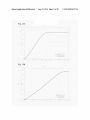
[0048] FIG. 1A is a printout of an oscilloscope output of the
initial accelerometer signal recorded during SSBO of a com
mercially available prior art breakaway set screw.
[0049] FIG. 1B is a graph of the test data of FIG. 1A
wherein the data has been converted to show acceleration
(g-forces) per unit time.
[0050]
FIG. 2 is a frontal view of a reduced shock break
away set screw according to one embodiment of the present
breaking off the upper portion of a breakaway set screw for
invention.
[0051] FIG. 3 is a cross sectional view taken along lines 3-3
of FIG. 2 of a reduced shock breakaway set screw according
to one embodiment of the present invention.
[0052] FIG. 4 is a fragmented cross sectional view taken
from FIG. 3 of the substantially annular groove of a reduced
shock breakaway set screw according to one embodiment of
use with a surgical construct at a de?ned torque using a
the present invention.
groove of the third aspect of the present invention includes
any of the embodiments described above wherein the sub
stantially annular groove may undergo a surface treatment.
[0042] The present invention also includes a method of
reducing shock to the patient and physician created when
reduced shock breakaway set screw having a threaded lower
[0053]
portion and an upper headportion separated by a substantially
annular groove having an upper radius, a lower radius, and a
the curve is the indicative of a material’s toughness.
[0054] FIG. 5B is a stress strain curve showing energy
substantially ?attened portion, separating the upper radius
dissipation.
and the lower radius.
[0055] FIG. 6A is a graph showing crack growth rate as a
function of crack size.
[0056] FIG. 6B is an illustration of the competing intrinsic
[0043] In another aspect, the present invention may include
a method of reducing shock to the patient and physician
created when breaking off the upper portion of a breakaway
FIG. 5A is a stress strain curve wherein area under
(promoting) and extrinsic (impeding) forces in crack propa
set screw for use with a surgical construct having the method
gation.
steps of: (i) placing the threaded lower end of a reduced shock
breakaway set screw according to the present invention
designed to break at a pre-de?ned torque into a threaded bore
of a surgical construct sized to receive it; and (ii) tightening
the reduced shock breakaway set screw to the pre-de?ned
torque with a torque applying tool until the upper head portion
of the reduced shock breakaway set screw shears away from
the threaded lower set screw portion of the reduced shock
[0057] FIG. 7 is a partial frontal view of a reduced shock
breakaway set screw according to one embodiment of the
breakaway set screw.
[0044]
In another aspect, the present invention may include
a method of reducing shock created during set screw break off
of a breakaway set screw for use with a surgical construct
having a threaded lower portion and an upper head portion
separated by a substantially annular groove comprising
present invention having apertures between the substantially
annular groove and an internal opening.
[0058] FIG. 8 is a partial frontal view of a reduced shock
breakaway set screw according to one embodiment of the
present invention having ribs running across the substantially
annular groove.
[0059] FIG. 9 is a partial frontal view of a reduced shock
breakaway set screw according to one embodiment of the
present invention having both apertures between the substan
tially annular groove and an internal opening and ribs running
across the substantially annular groove.
[0060] FIGS. 10A and 10B shows the axisymmetric cross
sections of the two most dissimilar geometries used for the
increasing the ratio of energy released from the plastic defor
mation of the material in the substantially annular groove to
axisymetric-with-twist computer modeling trials. FIG. 10A
the amount of energy released as kinetic energy from the
shows example no. LOR2 (“LOR2”) which has a simple
Aug. 21,2014
US 2014/0236237 A1
groove and 0.0002 inch ?llet radius, while FIG. 10B shows
example no. L3R8 (“L3R8”) which has a 0.0003 inch ?at at
the bottom of the groove with a 0.0008 inch ?llet radius. In
both, the lower edge is ?xed, while a moment about the
central axis is applied to the top edge.
[0061] FIGS. 11A-C reports pivot graph results of the para
metric Abaqus model testing showing (from top to bottom)
Abaqus variables ALLPD (11A), ALLSE (11B), ALLWK
other parts of the surgical construct. As used herein a surgical
construct for use with the spine is a multicomponent device
constructed from stainless or titanium-based steel, consisting
of solid, grooved, or slotted plates or rods (may be metal or
PEEK) that are longitudinally interconnected and anchored to
adjacent vertebrae using bolts, hooks, or screws.
[0068] The reduced shock breakaway set screw 10 has an
(11C).
outer surface 16 and can be divided into an upper head portion
11 and a lower threaded set screw portion 12, separated by a
[0062] FIGS. 12A and 12B provide graphs comparing the
output of axisymetric-with-twist computer modeling trials
reduced shock breakaway set screw 10 may have an internal
showing: (A) The maximum moment remains relatively con
stant while increasing in duration; and (B) The plastic dissi
opening 14 that runs axially down the center of the reduced
shock breakaway set screw from the upper head portion 1 1 to
substantially annular groove 13. Referring now to FIG. 3, the
pation of energy and total displacement (strain) increases
or into lower set screw portion 12. In one embodiment of the
signi?cantly.
present invention the internal opening 14 is machined into the
[0063] FIGS. 13A and 13B provide graphical results of the
energy and moment values for the plastic dissipation shown in
FIGS. 12A and 12B respectively. The thick line shows the
point where ?rst yield occurs, the circle at the peak shows
where the ?rst element is deleted, and the second circle shows
where the ?nal element is deleted.
[0064] FIG. 14 is a generic stress strain curve showing the
elastic and plastic deformation regions.
set screw blank as a blind bore running through what will be
the upper head portion into what will become the lower
threaded set screw portion of the reduced shock breakaway
set screw 10. In another embodiment the blind bore stops at
the top of what will become the lower threaded set screw
portion of the reduced shock breakaway set screw 10. The
internal opening 14 is further de?ned by inner surface 15. The
distance between inner surface 15 and outer surface 16
de?nes a wall thickness 17.
DETAILED DESCRIPTION OF THE
ILLUSTRATIVE EMBODIMENTS
[0065]
The present invention is generally directed to a
reduced shock breakaway set screw for use with medical
implants having improved geometry of the groove area
between the upper and lower portions of the set screw. The
geometry serves to slow down the fracturing process during
shearing, thereby increasing the proportion of energy dissi
pated as heat from plastic deformation of the material to the
amount of energy released as kinetic energy from elastic
deformation. The amount of energy released as shock to the
patient or the surgeon is determined by the amount of energy
released as kinetic energy of vibration as material elastically
deformed and then snaps back to its previous condition.
[0066] Referring now to FIG. 2, a reduced shock break
away set screw is shown, generally indicated by the numeral
10. The reduced shock breakaway set screw 10 can be made
of any ductile metal or other material that may be safely
implanted in the human body and will not deform at or about
the torque required for shearing. In one or more embodi
ments, the metal may be selected from titanium alloys, stain
less steel and cobalt-chromium alloys. In one embodiment the
reduced shock breakaway set screw 10 is made of a commer
[0069]
Upper head portion 11 is con?gured to mate with a
torque applying tool (not shown). Upper head portion 11 may
be hexagonal in cross section for some or all of its length and
sized to ?t within and mate with a drive socket of a socket
wrench or torque wrench, a manual torqueing instrument, or
other torque generating tool having a hollow end portion that
is hexagonal in cross section and intimately ?ts over the upper
head portion 11. As will be appreciated by those of skill in the
art, upper head portion 11 may have any cross sectional shape
so long as it mates with the torque applying tool in such a way
as to permit the torque applying tool to apply an amount of
torque suf?cient to cause the upper head portion 11 to shear
off of the threaded lower set screw portion 12. The upper head
portion 11 may also have a solid upper portion with a recess
shaped to receive within it the end portion of a torque apply
ing tool or a drive bit, so long as the arrangement permits the
torque applying tool to apply the necessary amount of torque
to cause the upper head portion 11 to shear off of the threaded
lower set screw portion 12.
[0070] Threaded lower set screw portion 12 has threads 18
and a set screw end 19. The inner surface 15, at the threaded
lower set screw portion 12, may contain a set of reverse
threads (not shown) to facilitate removal of the set screw with
cially available Ti-6Al-4V Titanium alloy. In one embodi
an easy out tool or other screw removal tool after it has been
ment the set screw 10 is made of a commercially available Ti
broken off from the upper head portion 11. Alternatively,
removal may be facilitated by providing a shaped recess in the
6Al-4V ELI Titanium alloy. In one embodiment the reduced
shock breakaway set screw 10 is made of a commercially
available 316L stainless steel. In one embodiment, the
reduced shock breakaway set screw 10 may be machined out
of a solid piece of a titanium alloy, stainless steel or cobalt
chromium alloy. In accordance with at least one aspect of the
present invention, the reduced shock set screw may undergo
any of the conventional or otherwise appropriate surface
treatments.
top of the lower threaded set screw portion 12 sized to mate
with any conventional drive bit or drive end used with a
torqueing instrument to impart counter rotations for removal
of the set screw portion 12. The threaded lower set screw
portion 12 is sized to ?t in a threaded bore located in a pedicle
screw head, connector, ring, band clamp, bone screw cap, or
other similar portion of a surgical construct for use with the
spine, to anchor a rod or other elongated member to a pedicle
[0067] The reduced shock breakaway set screw 10 may be
adapted to be used in securing a spinal rod or other elongated
member within a pedicle screw head, connector, ring, band
tightened as described above, the set screw end 19 comes into
clamp, bone screw cap, or otherportion of a surgical construct
engagement with the rod or other elongated member, holding
in such a way as to substantially eliminate translational or
it in place. The set screw end 19 can be any shape or con?gu
ration that can securely hold the rod or other elongated mem
rotational movement of the rod with respect to the vertebra or
screw.
[0071]
When reduced shock breakaway set screw 10 is
Aug. 21,2014
US 2014/0236237 A1
ber in place and prevent either translational or rotational
movement of the rod or other elongated member. Possible
con?gurations for set screw end 19 may include a v-shaped
point coaxial with the set screw portion 12, sharpened ring
with or without a v-shaped point coaxial with the set screw
portion 12, or any other conventional or otherwise suitable
amount of kinetic energy released from the elastic deforma
tion of the metal in the substantially annular groove, and,
accordingly, the shock transmitted to the patient and surgeon.
[0077] Given the same pre-set shearing torque for the same
material with identical bulk and surface properties, the geo
metric changes in the substantially annular groove 13 of the
con?guration.
set screw 10 can in?uence the energy release behavior of a
[0072] Substantially annular groove 13 runs around the
circumference of the reduced shock breakaway set screw 10
between the upper head portion 11 and threaded lower set
27, joined by a substantially ?attened portion 28, having a
length of e, the substantially ?attened portion 28 being tan
crack such that the maximum shock released upon breaking/
shearing is reduced. It has been found based on the theory of
Linear Elastic Fracture Mechanics (LEFM), that where the
stress at the moving crack tip is considered linear elastic with
two-dimensional stress, the crack undergoes a rapid, brittle
propagation through the structure’s thickness when it exceeds
a “critical stress intensity.” At this critical stress intensity, the
energy release rate (GIenergy per unit length along the crack
gential to both upper radius 26 and lower radius 27. The
tip) of the separating material (potential energy release of the
substantially ?attened portion 28 need not be perfectly ?at,
elastic strain) is greater than the crack resistance. The excess
of energy becomes kinetic energy which controls the crack tip
screw portion 12 of the set screw. In the embodiment shown in
FIGS. 2-4, the bottom of the substantially annular groove 13
is elongated, de?ning an upper radius 26 and a lower radius
but is generally non-circular and not part of either the upper
radius 26 or the lower radius 27. The precise dimensions of
the upper radius 26, lower radius 27, and substantially ?at
tened portion 28 may depend on the size of the set screw being
used. In one aspect of the present invention, the upper radius
26 or the lower radius 27 is greater than the groove wall
thickness 25. In one embodiment of the present invention, the
upper radius and lower radius may be from 1/64 inches to about
1A inches and the substantially ?attened portion 28 may have
a length l of from 0 inches to about 1/8 inches.
[0073] In an alternative embodiment of the present inven
tion, the substantially annular groove is a single arc having a
radius that is longer than the groove wall thickness 25. In this
embodiment, the length l of the substantially ?attened portion
28 may be 0.
[0074] The external work performed on the device by
applying torque to the reduced shock breakaway set screw 10
is primarily converted into either plastic dissipation energy or
recoverable elastic strain energy that manifests itself as
shock. FIG. 14 is a generic stress strain curve showing areas
of elastic and plastic deformation. Plastic deformation for
most materials is caused when the structure undergoes so
much stress that the bonds between individual atoms break
and reform to an adjacent atom. Plastic deformation happens
in the direction that these atoms move. Essentially, this con
cept relies on the material’s toughness, or energy absorption
potential before failure. Visually, one can see a material’s
toughness by observing the area under the engineering stress
strain curve (See FIG. 5A). When a metal is elastically
deformed, there is no such breaking and reforming of bonds
within the metal and if the material breaks/ shears under only
elastic deformation, the material will snap back to its original
shape releasing essentially all of the elastic strain energy as
kinetic energy in the form of vibrations (i.e. shock).
[0075] Therefore, it is believed that as the elastic strain
energy decreases relative to plastic dissipation energy, the
shock will also decrease. As would be clear to one of ordinary
skill in the art from simple geometry, as the upper head
portion of the breakaway set screw undergoes increased rota
tion before failure, then more elements must be experiencing
deformation assuming that the plastic strain limit of each
speed through the material, with the total kinetic energy equal
to:
[0078] Where:
[0079] Eh”: kinetic energy
[0080]
[0081]
G: energy release rate
R: crack resistance force.
Assuming that: (l) the stress during crack propagation is
constant; (2) G is independent of crack speed; and (3) R is
constant.
[0082]
Crack resistance and propagation forces are actually
a complex combination of a variety of forces, depending on
things such as environment, material, and crack/structure
geometry. The preceding equation is only a rough guide since,
for example, crack resistance does not remain constant,
because as crack growth rate is controlled by crack size (FIG.
6A) along with other factors. The primary groupings of these
forces that in?uence crack growth are intrinsic and extrinsic
as shown in FIG. 6B. See, Ritchie, R. O., Gilbert, C. 1., &
McNaney, J. M. (2000). Mechanics and mechanisms of
fatigue damage and crack growth in advanced materials.
International Journal of Solids and Structures. 37:311-329,
the disclosure of which is incorporated herein by reference.
Intrinsic forces stimulate crack growth and are dependent on
the material properties, while the extrinsic forces hinder
propagation and are primarily a function of crack size/geom
etry. Ductile materials such as metals predominantly toughen
intrinsically, whereas brittle materials toughen through
extrinsic forces. Material and process variabilities such as
strain rate, strain hardening, surface irregularities, surface
processing (e.g. Shot peening, electro polishing), and grain
structure all affect a part’s macroscopic behavior through
their in?uence on the microscopic intrinsic and extrinsic
properties.
[0083]
As a general rule, however, it is clear that: (l) the
crack propagation rate increases as the crack grows; (2) crack
propagation will become brittle when the growth rate is too
fast because R is smaller than the energy release rate, result
element is identical. As more elements experience deforma
ing in an abundance of kinetic energy (i.e. shock) and (3)
metals primarily toughen due to intrinsic crack initiation
tion, then more energy is dissipated plastically.
forces.
[0076]
The improved groove geometries of the present
invention act to increase the proportion of the energy that is
released as heat from the plastic deformation of the material
in the substantially annular groove, thereby reducing the
[0084]
The improved groove geometry of the present
invention has been found to slow the rate of crack growth
thereby dissipating more of the stored energy for plastic
deformation and eventually less as shock. By broadening the
Aug. 21,2014
US 2014/0236237 A1
substantially annular groove 13 and reducing or eliminating
guide crack propagation. The ridges or ribs 29 should force
the sharp corners or acute angles in the groove 13, the
additional cracks to require initiation and/or add resistance to
improved groove geometry of the present invention slows the
reduce crack growth rate thereby reducing kinetic energy
crack propagation by providing increased pathways along the
release. The ridges or ribs 29 should force additional cracks to
require initiation and/ or add resistance to reduce crack growth
grain boundaries for the crack to propagate, wherein dissipat
ing more energy in plastic deformation, thereby less as shock.
[0085] By contrast, the prior art SSBO breakaway set
screws having a substantially “V” shaped notch with straight
angled sides and a very sharply angled bottom, provide a
rate, thereby reducing energy release rate. Ideally, this design
failure experienced when the surgeon achieves the designed
torque. This is illustrated in FIGS. 1A and 1B by the high
acceleration peak at the start of the signal, which indicates
that crack initiation and propagation is rapid. This SSBO
crack speed, together with the set screw geometry, greatly
will cause signi?cant plastic deformation around the entire
circumference since the plastic zone will always be leading
the slowly propagating crack, while the process will still seem
instantaneous to the surgeon because of the greatly reduced
length that each crack must travel.
[0089] The embodiments shown in FIGS. 7-9 may have the
same cross sectional area being sheared, and, therefore, result
in an identical release of energy compared to the prior art
systems. However, this energy release is over a longer period,
in?uence the failure behavior of the prior art set screws, and
make the normally ductile material response of the metal
become primarily a brittle rupture.
mittent times within the time period of shearing failure.
Regardless of the shape of the pro?le curve, the area under the
sudden release of energy as a result of the instantaneous shear
[0086]
In the embodiment best seen in FIG. 7, there are one
or more apertures 30 running between the substantially ?at
tened portion 28 and the inner surface 15 of the inner opening
and may be continuous or occur in observable spikes at inter
curve should remain relatively constant if the cross section
remains the same since the same energy will be required to
shear it.
14. These apertures 30 may be evenly spaced along the sub
stantially annular groove 13. In an embodiment best seen in
FIG. 8, there are one or more ridges or ribs 29 running from
the upper radius to the lower radius of the substantially annu
lar grove 13. Ridges or ribs 29 may be any shape and may be
any periodic increase in groove wall thickness 25. These
ridges or ribs 29 may be evenly spaced along the substantially
annular groove 13. In one embodiment, the ridges or ribs 29
may be contiguous with the substantially ?attened portion 28
some or all of the upper and lower radii 26, 27. In one embodi
ment, there are both a plurality of apertures 30 and a plurality
EXAMPLES
[0090]
The following examples are offered to more fully
illustrate the invention, but are not to be construed as limiting
the scope thereof. Further, while some of examples may
include conclusions about the way the invention may func
tion, the inventor do not intend to be bound by those conclu
sions, but put them forth only as possible explanations. More
over, unless noted by use of past tense, presentation of an
example does not imply that an experiment or procedure was,
of ribs 29 alternately arranged and evenly spaced along the
or was not, conducted, or that results were, or were not actu
substantially annular groove 13 as in FIG. 9. In one embodi
ment, ridges or ribs 29 are variations in the groove wall
thickness 25.
respect to numbers used (e. g., amounts, temperature), but
[0087]
ally obtained. Efforts have been made to ensure accuracy with
some experimental errors and deviations may be present.
The purpose of the apertures 30 is to provide a
Example 1
geometry that initiates crack propagation at multiple points so
that there are no an extremely long cracks, since the crack
speed is in?uenced by crack size (FIG. 6B). The multiple
holes are intended to increase the amount of energy dissipated
through plastic deformation since each crack initiation site
Experimental and Evaluation Validation Of
Manufacturer Speci?ed Set Screw Break Off (SSBO)
Torque for PriorArt Set Screw
rely on the brittle kinetic energy of one crack spreading cir
[0091] As set forth above, the proper torque for the set
screws is critically important in pedicle screw systems. Not
enough torque can allow the stabilizing rod to slip. Over
cumferentially. At the tip of crack propagation, plastic defor
torque of the set screw can severely deform the screw threads,
mation dissipates energy, and this design causes plastic defor
causing them to lose strength, andpossibly allowing the rodto
slip when the patient later puts load on the spine. Materials
must undergo a certain amount of intrinsic toughening.
Therefore, in order for the part to fail, complete shear cannot
mation aron the entire circumference since the plastic zone
will always be leading the propagating crack. It has been
found that tubes with two holes have more ductility before
failure than tubes with one hole. The holes are a geometric
stress riser that initiates crack propagation. At the intrinsic tip
of slow crack propagation, plastic deformation dissipates
engineering and machine design theories, as well as perform
ing a test using a torque wrench, validated that the prior art set
screw tested does break at the torque speci?ed by the manu
facturer.
energy. The multiple holes are intended to increase the
[0092] The shear failure during SSBO was explored experi
mentally and by applying distortion energy theory to thin wall
amount of energy dissipated through this plastic deformation
torsion (TWT) and fully plastic torque (FPT) equations.
since each crack initiation site must undergo a certain amount
SSBO design torque of 11.00 N-m (as supplied by the manu
of intrinsic toughening and slow propagation. Therefore, the
facturer) was compared to an experimental torque wrench
measurement and to the torque required to reach the shear
brittle energy release at the crack tip cannot be the main driver
of crack propagation in these geometries, as the critical stress
strength calculated by distortion energy theory in both TWT
intensity must be reached independently in each section
and FPT.
between the holes.
[0088] The ridges or ribs 29 are meant to provide added
support so that the crack propagation does not initiate until the
FPT were obtaining the inner diameter (ID) and outer diam
eter (OD) of the set screw, and calculate the shear strength.
desired initial torque is reached and further, to delay and
First, digital imaging and micrometer readings were used to
[0093]
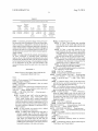
The basic information requirements of TWT and
Aug. 21,2014
US 2014/0236237 A1
determine the inner and outer diameters of the set screws at
the point of failure (Table 1). Second, From the Distortion
Energy (Von Mises) principles:
T
[0101] Finally, a torque wrench (valid from 3.6 N-m to 29
N-m) validated the maximum torque reached before break
off as approximately 11.3 N-m. A comparison of all the
failure torques is in Table 2.
0' ield
‘ 1d = y—
le
TABLE 2
3
Comparison of Torque Values
[0094] Using material data of titanium alloy 6-Aluminum
4-Vanadium (Ti-6AL-4V), which is the primary material
from which many implants are made, Quasi-static yield stress
for Ti-6Al-4V was determined to be 950 MPa. Therefore, '5
yield is about 548 MPa.
Method
Torque Value (N—m)
Design break—off torque (as supplied by
11.00 N—m
Medtronic)
Thin Wall Torsion (TWT)
11.24 N—m
Fully Plastic Torque (FPT)
11.2 N—m
Torque wrench
11.3 N—m
TABLE 1
Example 2
ID and OD measurements of prior art set screw
Validation from
From Digital Image Analysis
a micrometer
0.005235 In
0.0061111 In
0.0053 In
0.0061 In
Inner diameter (ID)
Outer diameter (OD)
Axisymetric-with-Twist Computer Modeling
Experiments
[0102] Axisymetric-with-twist computer modeling experi
ments have been conducted using commercially available
[0095] In thin wall torsion, the stress in the wall of a tube is
assumed to be independent of the radius. Therefore, the stan
dard torsional stress equation is combined with the circular
tube polar moment of inertia:
modeling software manufactured by Dassault Systemes Sim
ulia Corp. and sold under the tradename Abaqus (version
6.10-2). These experiments con?rmed that geometric
manipulations of the groove signi?cantly affects the plastic
behavior of the structure while still allowing the maximum
torque to be separately controlled.
[0103] An explanation of the different components of
energy that were tracked for the whole model may be found in
the “Energy Balance” section 1.5.5 of the Abaqus Theory
Manual, the disclosure of which is incorporated herein by
reference. These were referred to by the software as “?eld
variables,” withALLPD referring to the plastically dissipated
[0096]
Break-off occurs when there is full plasticity at '5
yield, since the stress is considered constant throughout. The
the model as it is turned. Another critical variable was rota
tional strain before failure. The rotation of each test was
constant and took exactly one time increment to reach the
mean radius is used:
TWM *7r * (0134 - 1134)
Tbreak' off I
32 * rmm
[0097] This break-off torque is 11.24 N-m.
[0098] Fully plastic torque of a hollow shaft is calculated by
subtracting what the torque carrying capacity would have
been of a rod (of the same material) with a diameter equal to
the ID from the torque carry capacity of a solid bar with the
diameter equal to the OD:
TtubeITsolid— Thollow
[0099]
energy and ALLSE referring to the recoverable elastic strain
energy. ALLWK refers to all of the external energy added to
The torque of each section, Tsolid and Thollow, is
calculated by:
?nal rotation location speci?ed (at a constant velocity).
[0104] The law of conservation of energy states that energy
can neither be created nor destroyed. In addition, since basic
material laws state that plastic strain is irreversible deforma
tion of a material, then the amount of plastically dissipated
energy accumulated can never be decreased. However, since
the Abaqus model being utilized deletes elements when they
have surpassed the strain limit de?ned by the material, the
plastically dissipated energy contained in each deleted ele
ment is also deleted. Therefore, since every shear model run
showed that the geometry sheared all the way through, the
point at which fracture completed is also the point at which
the last element was deleted and the last decrease in ALLPD
was observed.
[0105]
T=(12 )Ty 03
[0100] Distortion energy is again used for 13y. The value of
Tsolid is 32.56 N-m, and Thollow is 21.36 N-m. Thus, the
FPT break-off torque is:
Ttube:32.56—21.36:11.2 N—m
Modeling decisions were made based on recom
mendations given in “Classical Metal Plasticity” of the
Abaqus 6.10 Analysis User’s Manual of the disclosure of
which is incorporated herein by reference. The progressive
damage and failure models in Abaqus are able to model both
quasi-static and dynamic situations. It was determined that
the manually applied strain rates in the set screw break off are
not high enough to signi?cantly affect the failure stress, thus
quasi-static modeling was used. This assumption is due to the
Ti 6Al-4V yield strength used in the initial calculations (de
Aug. 21,2014
US 2014/0236237 A1
scribed above in Example 1), which corresponds to the actual
measured and designed for break off torque. This yield
strength is the quasi-static yield strength, as higher strain rates
result in higher yield strength. The damage model utilized
This result indicates that the failure strength of a tube under
torsion is primarily a function of the failure region’s mean
thickness, which remained constant, and therefore was not
affected by surrounding geometries.
was ductile damage (i.e. failure strain as a function of triaxi
[0110]
ality) since the validity of material models can be judged
based on their ability to correctly determine the failure strain
can best be seen by the pivot table graph in FIG. 11A. It also
shows the two geometries that have the lowest and highest
The general trend of geometry to plastic dissipation
throughout all loading conditions (as identi?ed by triaxiality
values of plastic dissipation. As expected, due to what is
values). Therefore, since the damage model used was de?ned
by maximum equivalent strain at a particular triaxiality,
known about stress risers, the smaller groove with the small
est radius has the lowest plastic dissipation and the widest
equivalent plastic strain (PEEQ) is used to visualize plastic
deformation. (Additional information may be found in
groove with the largest radius has the greatest plastic dissi
pation. The relatively sharp groove in LOR2 has only a small
Abaqus/CAE User’s Manual 12.9.3 “De?ning Damage” the
disclosure of which is hereby incorporated by reference in its
area of in?uence, while the widest groove of L3R8 spans, and
therefore affects, much more material. Since more material is
entirety.
in?uenced by the stress riders of L3R8, there will be more
[0106] The method used generally involved creating a 2D
axisymmetric sketch of the part, creating a material with
damage conditions, assigning the material to the part, creat
ing a mesh on the part using CGAX3 element that allows
twist, assigning node regions to which boundary/rotational
conditions were applied (FIG. 10), and setting the conver
gence behavior. The element type utilized, CGAX3, was par
ticularly important to the entire model and simulations
because it provided the 2D model an additional degree of
freedom. Traditional 2D axisymmetric analysis only allows
in-plane movement. Per Abaqus Analysis User’s Manual
25.1.6 “Axisymmetric solid element library,” the disclosure
of which is hereby incorporated by reference in its entirety,
the element type CGAX3 also allows elements the freedom to
twist about the axis. Movement, moment, and stresses due to
elements experiencing plastic deformation.
[0111] Despite the change in stress concentrations, the
maximum moment required to shear each cross section expe
rienced negligible variation (FIG. 12A. Therefore, since the
minimum cross section did not change, this moment remains
primarily a function of the thinnest cross section of the groove
as predicted by the equations above in Example 1. However,
the increased amount of displacement over which the moment
must be applied causes the external work done on the struc
ture to increase, since work is force times displacement. FIG.
12A illustrates the relative shapes of the moment curves for
LOR2 and L3R8. Additionally, whereas FIG. 11A shows the
relative maximums of the plastic dissipation (“ALLPD”),
FIG. 12B shows the curve pro?le for the trials for LOR2 and
L3R8. The decreasing plastic dissipation energy (“ALLPD”)
torsion on the modeled structure could not have been obtained
term in FIG. 11A is believed to be an inaccurate artifact due to
without this additional degree of freedom. The overall length
element deletion. When the elements were deleted after they
had reached the complete failure criteria de?ned by the mate
rial model, the energy terms associated with those elements
of the modeled sections remained the same; however the ?llet
radius and length of the substantially ?attened portion of the
bottom of the groove was varied. The ?llet radii values were
are also deleted. This also shows that the deformation
0.0002 in (“R2”), 0.0004 in (“R4”), and 0.0008 in (“R8”) with
the length of the ?attened bottom section ranged from 0.0 in
(“L0”) (i.e. simple semicircle groove) to 0.0003 in in incre
ments of 0.0001 in (“L1,” “L2,” and “L3,” respectively).
occurred at a slower rate and over a longer time when com
These measurements were only used to determine relative
performance in Finite element modeling, and they are not the
intended measurements of the invention herein.
[0107] Constants were the minimum and maximum wall
thicknesses and total height of the model. A parametric study
paring the wider L3R8 groove to the narrow LOR2 groove,
which is useful because more elongation means more plastic
dissipation as discussed above. The displacement at which
the structure completely fails for the LOR2 model was 0.54 of
the rotation cycle, and the displacement at which the structure
completely fails for the L3R8 model was 0.94 of the rotation
cycle. This is a 74% increase in rotation before failure. The
researchers consider this entire increase to be due to plastic
was conducted with every combination of these variables (i.e.
strain, since only 3.09E-7 of the rotation cycle is completely
12 total models) to show how these geometric changes
affected plasticity. These combinations were labeled by their
elastic for the LOR2 model and 0.0142 is elastic for L3R8.
Using the geometric extremes, the behavior of the structure in
length (L0, L1, L2, L3) followed by their radius (R2, R4, R8),
relation to the curve pro?les is shown in FIGS. 13A-B. It
e.g. L3R8. The two extreme cases of these models (LOR2 and
should be noted that complete failure was de?ned by the
L3R8) are illustrated in FIGS. 10A and 10B for clarity.
Detailed information on how the 2D-axisymmetric-with
twist model was created is set forth below in Appendix A.
researchers to be the moment when the last element was
[0108]
By lengthening the ?attened bottom section of the
groove in a tube section and reducing the stress concentra
tions from the ?llet radii in a 2D axisymmetric model, the
percent of work that went into plastic energy dissipation was
increased by 36%. In addition, the radians that the structure
rotated before failure was shown to increase by 74%, along
with the area experiencing plastic yielding. All these results
were consistent, showing that the plasticity of a structure is
dependent on the speci?c geometry surrounding the failure
region.
[0109]
deleted, and this point is not the same moment when the
ALLPD curve becomes level.
[0112] Although the recoverable elastic energy is slightly
higher for L3R8 than for LOR2 (FIG. 11B), this increase is
negligible considering the overall magnitude of the work
done as shown by the output graphs of LOR2 and L3R8 in
FIGS. 13A, 13B. As discussed above, this is the reason why
the ratio of recoverable elastic strain to plastic energy dissi
pation was used. Numerically, the ALLSE/ALLPD ratio for
the smallest groove (LOR2) was 0.0274, and the same ratio for
the largest groove (L3R8) was 0.0174. This is over a 36%
decrease in the ratio, showing that the geometric structure
In all cases the maximum torque required for the
structure to experience torsional failure was almost identical.
in?uences the plastic behavior of a material. A numerical
summary of results for LOR1 and L3R8 is found in Table 3.
Aug. 21,2014
US 2014/0236237 A1
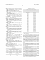
TABLE 3
Comparison ofthe two geometric extremes LOR2 and L3R8
LOR2
L3R8
Maximum
Maximum
Plastic
Total
Rotation
before
Elastic
dissipation
energy
energy
ALLSE/
work
complete
Maximum
done
shear
moment for
(ALLSE)
(ALLPD)
2.442E—06
2.796E—06
8.902E—05
16.073E—05
ALLPD
(ALLWK)
failure
shear failure
.0274
.0174
36%
Decrease
7.430E—05
14.352E—05
928°
1616"
74%
Increase
6.307E—04
6.293E—04
[0113] In summary, geometric changes to the groove pro
?le around the outer circumference of the tube caused plas
ticity to increase, as indicated by a decrease in the ratio of
elastic energy to plastic dissipation energy and an increase in
Approximately
the same
[0122] ii) De?ne the groove by:
[0123] (1) Draw a short straight edge extending
from the ends of the nearby right vertical lines
toward the left side, constrain these lines as hori
zontal
radians revolved before complete shear failure. Through all
[0124]
geometries, the tube was a constant material (Al-5083-H116)
and the maximum moment before failure remained approxi
(2) Draw a semi-circle (de?ned by two
points) between the ends of the two new straight
mately constant.
[0114] It is thus evident that the reduced shock breakaway
lines, de?ning the semi-circle radius (LOR2 groove
is 0.0002), create a “tangent” constraint between
set screw constructed as described herein substantially
the semi-circle and the two new horizontal lines
improves the art. Only particular embodiment(s) have been
[0125] (3) Draw an “Isolated Point” midway on the
circumference of the semi-circle location marker
presented and described in detail, and the invention should
not be limited by the drawings or the description provided.
will indicate when this point is being selected by
For an appreciation of the true scope and breadth of the
turning from a cross to a ?lled-in circle)
[0126]
invention, reference should be made only to the claims that
follow.
APPENDIX A
[0127] iii) Con?rm the sketch created is a closed struc
ture, otherwise it will be invalid
[0128]
Abaqus (Version 6.10-2) Steps Used to Build the 2D
Axisymmetric Model with Twist
(4) De?ne the length between this new point
and the left edge (For this thesis: 0.0004)
c) Hit “Esc” on keyboard
[0129] d) Click “Done” just below the view-port
[0130]
2) PARTITIONING THE PART . . . (from top menu
. . . )“Tools”, “Partition. . .”, select “Face”, select “Sketch”
Notes:
[0131]
[0115] 2D axi-symmetric CGAX3 element gives additional
twist angle degree of freedom
a) (from top menu . . . ) “Add”, “Line”, “Rect
angle”
view-port . . . ) Select “Module: Part”
[0132] b) Click the left-top corner of the tube-wall to
start the ?rst box and click somewhere just above the
groove on the right side of the tube-wall
[0133] c) Click the left-bottom comer of the tube-wall to
start the second box and click somewhere just below the
groove on the right side of the tube-wall
[0118]
[0134]
[0116]
Disadvantage of axisymmetric is that one cannot
use explicit methods
[0117] Units of values must be kept consistent by the user
PART MODULE: . . . (from pull-down window just above
1) CREATING THE PART . . . (from top menu . . .
) “Part”, “Create . . . ”,
[0119]
a) name the part “tube” on the text input box,
select “Axisymmetric”, select “Deformable”, select
“Shell”, check “Include twist” (creates a generalized
axisymmetric model that allows rotational movements
and force calculations), specify “Approximate size” to at
least twice as big as the greatest cross section length or
the radius, whichever is greatest (For this thesis: 0.012),
click “Continue”
[0120] b) Draw desired cross-section with a de?ned
radius. For LOR2 groove in this thesis:
[0121]
i) 0.00265 radius (length from center line to
left-most straight edge of tube wall), 0.0058 tube
height (continuous vertical dimensioned length on the
d) (from top menu . . . ) “Add”, “Dimension”,
de?ne the length slightly away from the start of the
groove on both sides such that the region of interest does
not extend into either box (For this thesis, the plastic
deformation will not extend into either box if both
lengths are 0.0002)
[0135] e) Hit “Esc” on keyboard
[0136] f) Click “Done” just below the view-port
PROPERTY MODULE: . . . (from pull-down window just
above view-port . . . ) Select “Module: Property”
[0137]
3) DEFINING MATERIAL . . . (from top menu . . .
) “Material”, “Create . . . ” (seeAPPENDIX B herein for the
AL5083-H116 values)
[0138]
a) Name the material as desired (For this thesis:
“A15083”)
[0139] b) General, Density
left side, two non-dimensioned vertical lengths on the
right where one extends from the base and one
[0140] c) Mechanical, Elasticity, Elastic (E, Poisson’s
extends from the top, but neither touch one another),
0.0008 regular wall thickness on the upper and lower
[0141] d) Mechanical, Plasticity, Plastic (tabular input of
horizontal boundaries of the tube cross section
ratio)
“Yield Stress” and “Plastic Strain”)