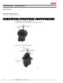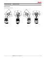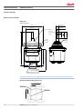
1
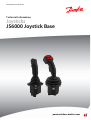
MAKING MODERN LIVING POSSIBLE
Technical Information
Joysticks
JS6000 Joystick Base
powersolutions.danfoss.com
Technical Information
JS6000 Joystick Base
Revision history
Table of revisions
Date
Changed
Rev
November 2015 Converted to Danfoss layout
1102
June 2010
Single or Dual Axis Options images; Dimensions and Installation, revised dimensions to
include 18 pin connector, added recommended mounting panel cut-out illustration, and
updated installation instructions.
KA
February 2010
Axis base image, A Grip Front Plate Diagram illustration, Environmental Characteristics
JA
September 2009 Content update
IA
January 2008
HA
A grip front plate diagram updated
November 2007 Grip options model code details; mechanical options: friction hold torque
GA
June 2007
Corrected temperature and length conversion
FA
June 2007
Text changes and addition of CAN+
EA
April 2007
Text changes
D
February 2006
Text changes
C
November 2005 Feature updates
B
May 2005
A
Hall sensor pinouts
December 2004 Initial release
2
520L0760 • Rev 1102 • November 2015
Technical Information
JS6000 Joystick Base
Contents
General information
Product configuration
Model code details
JS6000 CAN messages
CAN message protocol
Overview..............................................................................................................................................................................................5
Features and options...................................................................................................................................................................... 5
Product configuration model code............................................................................................................................................6
Base model code...............................................................................................................................................................................7
Grip model code............................................................................................................................................................................... 9
Code B: Single or dual axis options......................................................................................................................................... 10
Code C: Shaft sensor and output options............................................................................................................................. 12
Potentiometer sensor............................................................................................................................................................. 12
Center tap.............................................................................................................................................................................. 12
Directional potentiometer switches.............................................................................................................................13
Dual potentiometer outputs per axis................................................................................................................................13
Hall effect sensor.......................................................................................................................................................................14
Controller Area Network (CAN) output.............................................................................................................................14
CAN (configuration model code CAN).........................................................................................................................14
CAN+ (configuration model code CPL)....................................................................................................................... 14
Pulse Width Modulated (PWM) output.............................................................................................................................14
PWM (configuration model code PWM)..................................................................................................................... 14
Code D: Centering return spring options..............................................................................................................................15
Code E: Hardware configuration.............................................................................................................................................. 15
Code F: Mechanical options....................................................................................................................................................... 16
Code G: Microswitch option.......................................................................................................................................................18
Code H: Electrical interface options........................................................................................................................................ 19
Analog...........................................................................................................................................................................................19
CAN 2.0B, J1939 protocol.......................................................................................................................................................19
CANopen 2.0B, J1939 protocol............................................................................................................................................ 19
PWM ............................................................................................................................................................................................. 19
H1 electrical interface options............................................................................................................................................. 19
H2, 3 joystick location/CAN source address....................................................................................................................19
H4 CAN proportional output................................................................................................................................................20
Code I, J, K, L: Grip options..........................................................................................................................................................20
CAN option.......................................................................................................................................................................................21
CAN+ option.................................................................................................................................................................................... 21
CAN+ external inputs................................................................................................................................................................... 21
Analog inputs (AIN)..................................................................................................................................................................21
Digital inputs (DIN)...................................................................................................................................................................21
SAE J1939 CAN message specification...................................................................................................................................23
SAE J1939 basic joystick message...................................................................................................................................... 23
Data field......................................................................................................................................................................................23
Basic joystick message data field descriptions.............................................................................................................. 23
Joystick X-axis neutral position status.........................................................................................................................24
Joystick X-axis handle left negative position status............................................................................................... 25
Joystick X-axis handle right positive position status..............................................................................................25
Joystick X-axis position status........................................................................................................................................ 25
Joystick Y-axis neutral position status......................................................................................................................... 25
Joystick Y-axis handle back negative position status............................................................................................ 26
Joystick Y-axis handle forward positive position status........................................................................................26
Joystick Y-axis position status.........................................................................................................................................26
SAE J1939 extended joystick message............................................................................................................................. 26
SAE J1939 error (DM1) messages........................................................................................................................................27
SAE CANopen protocol information....................................................................................................................................... 29
A grip button and rocker CAN naming conventions........................................................................................................ 29
Top and operator present switch naming conventions.............................................................................................30
520L0760 • Rev 1102 • November 2015
3
Technical Information
JS6000 Joystick Base
Contents
Proportional rocker naming conventions........................................................................................................................30
MG grip button CAN naming conventions...........................................................................................................................31
Product installation
Specifications
4
Dimensions and installation...................................................................................................................................................... 32
Dimensions................................................................................................................................................................................. 32
Recommended mounting panel cut-out.........................................................................................................................32
Installation...................................................................................................................................................................................33
Machine wiring guidelines......................................................................................................................................................... 33
Joystick safety..................................................................................................................................................................................34
JS6000 connector pin assignments general information................................................................................................34
Pin assignments..............................................................................................................................................................................35
CAN output connector pin assignments..........................................................................................................................35
CAN output mating connector DEUTSCH DTM06-6S..................................................................................................35
CAN+ and PWM output connector pin assignments.................................................................................................. 36
CAN+ and PWM output mating connector DEUTSCH DT16-18SB......................................................................... 37
Potentiometer sensor with analog output connector pin assignments.............................................................. 38
Analog output mating connector ..................................................................................................................................... 39
Hall effect sensor with analog output pin assignments ............................................................................................40
Mechanical characteristics..........................................................................................................................................................41
Electrical characteristics...............................................................................................................................................................41
Microswitch characteristics........................................................................................................................................................ 43
Sensor power supply ratings..................................................................................................................................................... 43
Environmental characteristics................................................................................................................................................... 43
520L0760 • Rev 1102 • November 2015
Technical Information
JS6000 Joystick Base
General information
Overview
The JS6000 Joystick Base has been specially developed to meet the harsh operating requirements of
today’s mobile machines. The JS6000 features metal construction with a large diameter stainless steel
operating shaft, an innovative ball and socket gimbal design manufactured from pressure die cast zinc
alloys, a custom high strength material for the center return cone, and optional contactless Hall effect
sensing technology.
The CAN+ version of the JS6000 base allows the value and state of up to eleven digital or seven digital
and four analog inputs from external-to-the-joystick sources to be broadcast along with joystick
Controller Area network (CAN) messages.
The Pulse Width Modulation (PWM) version of the JS6000 base can be used to directly drive a valve, such
as the H1 hydrostatic transmission, without an intermediate microcontroller. This version allows joystick
operating parameters (e.g. ramp rates, button function assignments, output characteristics) to be
configured using the PLUS+1® Service Tool interface. Refer to JS6000 PWM User Manual, 11060942 for
instructions and information required to configure JS6000 PWM joystick options.
The flexible design of the JS6000 offers many options, making it the right choice for applications that
require more than a simple dual axis joystick with spring return to center.
JS6000 joystick base
Features and options
•
•
•
•
•
•
•
Hall effect or potentiometer sensing (model dependent)
One or two sensors per axis for redundancy
Single or dual axis
Mechanical direction switches
2 centering spring forces
3 available friction-hold options
Output options:
‒ Analog
‒ CAN 2.0B, J1939 protocol
‒ CANopen protocol
‒ High current PWM
•
Multiple grip options:
‒ HKN — plain knob
‒ MG — with operator trigger and hand rest
‒ A— configurable ergonomic
‒ Custom designed grips
•
External-to-joystick analog and digital information included in JS6000 CAN+messages
520L0760 • Rev 1102 • November 2015
5
Technical Information
JS6000 Joystick Base
Product configuration
Product configuration model code
Use the JS6000 product configuration model code to specify particular features when ordering a JS6000
joystick. The model code begins with the product family name: JS6000. Fill in the remaining fields to
configure the product with the desired features.
The model code includes both joystick base and joystick grip information. JS6000 Joystick Base Technical
Information Manual, 520L0760 provides information required to configure the base portion of the
joystick. JS1000, JS6000 Joystick Grips Technical Information Manual, 520L0872 provides information
required to configure JS6000 joystick grips.
Product configuration model code example
J S 6 0 0 0
6
X Y
H M M
H
S
N L
N
520L0760 • Rev 1102 • November 2015
J 3 3 1
A 0 H 0
R
V
N N N N N N N N
Technical Information
JS6000 Joystick Base
Product configuration
Base model code
JS6000 product configuration model code example
A
B
C
D
E
F
G
H
I
J
K
L M NO P Q R S
J S 6 0 0 0
X Y
H M M
H
S
N L
N
J 3 3 1
A 0 H 0
R
V
N N N N N N N N
Base
Grip
A—Product series
Code
Description
JS6000
Series JS6000 Joystick
B—Operational axis options
Code
Description
XY
Bi-directional: X and Y axis
NY
Uni-directional: Y axis only (required for friction-holding)
C—Shaft position sensing and output options
Code
Description
PRR
Potentiometer: single output per axis; Vo = 10 to 90% of Vs; ±1.5° neutral threshold
PQQ
Potentiometer: single output per axis; Vo = 25 to 75% of Vs; ±1.5° neutral threshold
PSS
Potentiometer: single output per axis; Vo = 10 to 90% of Vs; ±5° neutral threshold
PTT
Potentiometer: single output per axis; Vo = 25 to 75% of Vs; ±5° neutral threshold
PUU
Potentiometer: dual output per axis; Vo = 10 to 90% of Vs; ±1.5° neutral threshold
HMM
Hall effect: dual sensors per axis; Vs = 5 VDC; Vo = 0.5 to 4.5 VDC
CAN
Hall effect: dual sensors per axis; Vs = 9 to 36 VDC; CAN 2.0B J1939 communication, 6 pin connector
CANopen
Hall effect: dual sensors per axis; Vs = 9 to 36 VDC; CANopen 2.0B J1939 communication, 6 pin connector
CPL
Hall effect: dual sensors per axis; Vs = 9 to 36 VDC; CAN 2.0B communication, 18 pin connector
PWM
Hall effect: dual sensors per axis; Vs = 9 to 36 VDC; high current PWM and digital outputs
*
*
* See H1 electrical interface options on page 19.
D—Centering spring options
Code
Description
H
Heavy force
M
Medium force
F
Friction-hold (position maintained, center detent)
E—Gate pattern options
Code
Description
S
Square, full output at 45 degree
520L0760 • Rev 1102 • November 2015
7
Technical Information
JS6000 Joystick Base
Product configuration
F—Mechanical options
Code
Description
NL
No mechanical option; spring return to center only
FB
Friction-held in Y axis; no X axis; center detent; 1.25 Nm [0.92 lb•ft] friction-hold force; 2.5 Nm [1.66 lb•ft]
breakout force
FC
Friction-held in Y axis; no X axis; center detent; 1.25 Nm [0.92 lb•ft] friction-hold force; 3.25 Nm [2.40
lb•ft] breakout force
HC
Friction-held in Y axis; no X axis; center detent; 2.25 Nm [1.66 lb•ft] friction-hold force; 4.0 Nm [2.95 lb•ft]
breakout force
G—Direction (microswitch) options
8
Code
Description
N
No switches
Y
Microswitches installed
520L0760 • Rev 1102 • November 2015
Technical Information
JS6000 Joystick Base
Product configuration
Grip model code
JS6000 product configuration model code example
A
B
C
D
E
F
G
H
I
J
K
L MN O P Q R S
J S 6 0 0 0
X Y
H M M
H
S
N L
N
J 3 3 1
A 0 H 0
R
V
N N N N N N N N
1 2 3 4
H1—Electrical interface options
Code
Description
S
Analog (DC voltage output)
J
CAN, SAE J1939 protocol
W
PWM output
P
CANopen protocol (default: 125 Kbit band rate)
H2, 3—CAN source address*
Code
Description
NN
None—use with analog outputs when H1 = S
33
Source address = 0x 33 (use this source address with PWM outputs.)
34
Source address = 0x 34
35
Source address = 0x 35
36
Source address = 0x 36
*Consult the factory if additional source addresses are required.
H4—Joystick output type
Code
Description
N
None—use with analog and PWM outputs
1
CAN full scale output = 1000 counts
I, J, K, L, M, N, O, P, Q, R, S—Grip options
JS1000, JS6000 Joystick Grips Technical Information, 520L0872 provides information required to configure
the JS6000 joystick grip.
520L0760 • Rev 1102 • November 2015
9
Technical Information
JS6000 Joystick Base
Model code details
Code B: Single or dual axis options
JS6000 product configuration model code B
B
J S 6 0 0 0
Code B designates the number of operational axes.
Single Axis Base—NY with friction hold option in the configuration code
-Y Axis
+Y Axis
Dual Axis Base—XY in the configuration code
+X Axis
+Y Axis
-Y Axis
-X Axis
Orientation Mark
(lift boot)
2456B
10
520L0760 • Rev 1102 • November 2015
Technical Information
JS6000 Joystick Base
Model code details
X and Y Operation (or movement).
20° ± 0°
20° ± 0°
20° ± 0°
20° ± 0°
20° ± 0°
20° ± 0°
20° ± 0°
20° ± 0°
P200 001
520L0760 • Rev 1102 • November 2015
11
Technical Information
JS6000 Joystick Base
Model code details
Code C: Shaft sensor and output options
JS6000 product configuration model code C
C
J S 6 0 0 0
X Y
P R R
Code C designates the shaft sensing technology; potentiometer or Hall effect; and the electrical output
characteristics of the joystick base.
C—Shaft position sensing and output options
Code
Description
PRR
Potentiometer: single output per axis; Vo = 10 to 90% of Vs; ±1.5° neutral threshold
PQQ
Potentiometer: single output per axis; Vo = 25 to 75% of Vs; ±1.5° neutral threshold
PSS
Potentiometer: single output per axis; Vo = 10 to 90% of Vs; ±5° neutral threshold
PTT
Potentiometer: single output per axis; Vo = 25 to 75% of Vs; ±5° neutral threshold
PUU
Potentiometer: dual output per axis; Vo = 10 to 90% of Vs; ±1.5° neutral threshold
HMM
Hall effect: dual sensors per axis; Vs = 5 VDC; Vo = 0.5 to 4.5 VDC
CAN*
Hall effect: dual sensors per axis; Vs = 9 to 36 VDC; CAN 2.0B J1939 communication, 6 pin connector
CANopen*
Hall effect: dual sensors per axis; Vs = 9 to 36 VDC; CANopen 2.0B J1939 communication, 6 pin connector
CPL
Hall effect: dual sensors per axis; Vs = 9 to 36 VDC; CAN 2.0B communication, 18 pin connector
PWM
Hall effect: dual sensors per axis; Vs = 9 to 36 VDC; high current PWM and digital outputs
* See H1 electrical interface options on page 19.
Potentiometer sensor
The potentiometer sensor electrical connections are made via a 16 pin AMP 040 series MULTILOCK
connector mounted on the base of the unit.
Potentiometer outputs are ratiometric. The output value is dependent on the supply voltage. When the
joystick handle returns to center, the output will be between 48% and 52% of supply voltage (Vs).
Potentiometer sensor specifications
Minimum load impedance
1 MΩ recommended
Maximum wiper current
5 mA
Supply voltage
> 36 Vdc
Center tap/switch alignment
Within 0.5º
Potentiometer electrical angle
± 18º
Center tap angle
± 2.5º
Insulation resistance at 50 Vdc
> 50 MΩ
Center tap
A center tap is standard on all potentiometer tracks, where 50% of the supply voltage can be supplied to
force the sensor voltage to this known reference. When the center tap is not connected there will be a
center dead band (where the voltage output does not change on initial deflection) and the output
voltage will be between 48 and 52% of the supply voltage.
12
520L0760 • Rev 1102 • November 2015
Technical Information
JS6000 Joystick Base
Model code details
Directional potentiometer switches
Potentiometer tracks have directional and normally closed (center on) position switches that operate at
the angles shown in the table below. Switch outputs are independent of the proportional potentiometer
elements on each axis and can be terminated by the customer to provide directional or center on/off
data to the control system.
Directional potentiometer switches specifications
Maximum load current
200 mA resistive
Maximum supply voltage
> 36 Vdc
Directional potentiometer switch circuit diagram
Handle Direction Switch
Handle Direction Switch
Pot
Pot
Back
13 14 9
Right
Left
Forward
Center Tap
Center Tap
16 Pin Connector
16 Pin Connector
12
11 10 16 1
7
8
3
Y-axis Pin Numbering
6
5
4
2 15
X-axis Pin Numbering
– Wiper Symbol
Potentiometer track outputs
Minimum output
Voltage (% Vs)
Maximum output
Voltage (% Vs)
Switch track angle
Resistance kΩ
Order code
10 ± 2
90 ± 2
±1.5º
1.6 to 2.4
R
25 ± 2
75 ± 2
±1.5º
2.2 to 3.6
Q
10 ± 2
90 ± 2
±5º
1.6 to 2.4
S
25 ± 2
75 ± 2
±5º
2.2 to 3.6
T
W
Warning
Potential uncommanded machine movement. When a JS6000 joystick with the 25% to 75%
potentiometer output option (designated Q or T) is used to directly drive a PVG valve, if the power or
ground side of the joystick is lost, there is a risk of the valve going full on in one direction or the other. To
avoid the possibility of unintended machine motion, the PVG valve must have Active Fault Monitoring.
Dual potentiometer outputs per axis
Dual potentiometer outputs are available that feature independent power inputs and sensor outputs.
The secondary potentiometer output connections are via an 8 pin AMP® connector. Secondary
potentiometer outputs do not provide secondary directional and center switches.
Hall sensing and dual potentiometer outputs are not available together.
520L0760 • Rev 1102 • November 2015
13
Technical Information
JS6000 Joystick Base
Model code details
Dual potentiometer track selection
Minimum output
Voltage (% Vs)
Maximum output
Voltage (% Vs)
Switch track angle
Resistance kΩ
Order code
10 ± 2
90 ± 2
±1.5º
1.6 to 2.4
U
Hall effect sensor
The Hall effect sensor option includes dual sensors per axis. The sensors can be supplied from two
separate regulated 5 V supplies for a higher degree of redundancy, or can be supplied from a single
regulated 5 V supply.
Hall effect sensing electrical connections are made via a 12 pin AMP® 040 series MULTILOCK connector on
the base of the unit.
JS6000 Hall effect sensors are affected by temperature. Output values change temporarily by 2.6% and
permanently by 0.6% when subjected to a -40°C (-40°F) to 80°C (176°F) operating temperature range
cycle.
Hall effect sensor specifications
Supply voltage (Vs)
5 Vdc regulated
Minimum output voltage
10% ± 4% Vs
Center voltage
50% ± 2% Vs
Maximum output voltage
90% ± 4% Vs
Controller Area Network (CAN) output
Three versions of JS6000 CAN joysticks are available:
A grip
MG grip
HKN grip
•
•
•
CAN (configuration model code CAN)
CAN 2.0bB J1939 protocol and CANopen 2.0B J1939 protocol (reference Code H: Electrical interface options
on page 19 product configuration model code, under H1 electrical interface options on page 19).
CAN+ (configuration model code CPL)
CAN+ output broadcasts joystick shaft position, grip switch states, grip proportional rocker position and
the state and value of up to 11 digital (DIN) or 7 digital (DIN) and 4 analog (AIN) inputs from sources
external to the joystick. The CAN+ option joystick base has an 18 pin DEUTSCH connector.
Pulse Width Modulated (PWM) output
One version of the JS6000 PWM joystick is available.
PWM (configuration model code PWM)
The PWM version of JS6000 joystick has two bi-directional PWM channels and six digital ouputs. The
PWM option joystick base has an 18 pin DEUTSCH connector.
14
520L0760 • Rev 1102 • November 2015
Technical Information
JS6000 Joystick Base
Model code details
Code D: Centering return spring options
JS6000 product configuration model code D
D
J S 6 0 0 0
X Y
H M M
H
Code D designates centering spring force options.
The center spring returns the joystick to its center position when released by the operator and provides
the physical resistance to movement when the joystick is operated. Two levels of spring force are
available: heavy and medium. Spring force is selected by choosing a letter from the order character
column of the following table.
W
Warning
Potential uncommanded machine movement. The spring choice affects the joystick’s ability to resist
system vibrations. Each of the following springs give a different product harmonic range. This, in
combination with critical mass differences as a result of grip choice, results in each system (joystick and
machine) having different vibration characteristics. With this in mind, please consider the vibration range
of the system and determine whether any resonance exists in the joystick. Resonance causes dither and
could cause the joystick to leave neutral.
Centering spring selection
Spring option
Breakout force on axis
Force at full deflection
Order code
Heavy duty spring
12 to 19 N [2.7 to 4.3 lbf]
31 to 47 N [6.7 to 10.6 lbf]
H
Medium duty spring
6 to 8.5 N [1.3 to 1.9 lbf]
15 to 23 N [3.4 to 5.2 lbf]
M
The above forces are measured 55 mm (2.17 in) from the joystick mounting surface and are perpendicular
to the shaft.
Code E: Hardware configuration
JS6000 product configuration model code E
E
J S 6 0 0 0
X Y
H M M
H
S
Code E designates hardware configuration.
JS6000 joysticks have a square gate pattern as the standard configuration. This is designated as S in the
configuration code and includes a standard label.
Gate selection
Gate option
Characteristics
Order code
Square
± 20º mechanical travel (on axis)
S
The square gate offers full X and Y outputs when the joystick is moved to the corner positions.
520L0760 • Rev 1102 • November 2015
15
Technical Information
JS6000 Joystick Base
Model code details
Code F: Mechanical options
JS6000 product configuration model code F
F
J S 6 0 0 0
X Y
H M M
H
S
N L
Code F designates joystick mechanical options.
JS6000 joysticks are available with a friction-hold option. With this option, the joystick handle position
will remain in a position set by the operator and will not automatically return to center. This option is only
available in a single (Y) axis configuration. Four levels of friction/breakout from center force are available.
Friction-hold selection
Friction-hold torque
Center detent breakout torque
No mechanical options
Order code
NL
1.25 Nm (0.92 lbft)
2.50 Nm (1.84 lbft)
FB
1.25 Nm (0.92 lbft)
3.25 Nm (2.40 lbft)
FC
2.25 Nm (1.66 lbft)
4.00 Nm (2.95 lbft)
HC
JS6000 FB option
5.0
4.5
4.0
3.5
3.0
2.5
2.0
Torque (N .m)
1.5
1.0
0.5
21 20 19 18 1716 15 14 13 12 11 10 9 8 7 6 5 4
0.0
3 2 1 0 1 2 3 4 5 6 7 8 9 10 11 12 13 14 15 16 17 18 19 20 21
-0.5
-1.0
-1.5
-2.0
-2.5
-3.0
-3.5
-4.0
-4.5
-5.0
Angle (°)
16
520L0760 • Rev 1102 • November 2015
2458
Technical Information
JS6000 Joystick Base
Model code details
JS6000 FC option
5.0
4.5
4.0
3.5
3.0
2.5
2.0
Torque (N .m)
1.5
1.0
0.5
21 20 19 18 1716 15 14 13 12 11 10 9 8 7 6 5 4
0.0
3 2 1 0 1 2 3 4 5 6 7 8 9 10 11 12 13 14 15 16 17 18 19 20 21
-0.5
-1.0
-1.5
-2.0
-2.5
-3.0
-3.5
-4.0
-4.5
-5.0
Angle (°)
2459
JS6000 HC option
5.0
4.5
4.0
3.5
3.0
2.5
2.0
Torque (N .m)
1.5
1.0
0.5
21 20 19 18 1716 15 14 13 12 11 10 9 8 7 6 5 4
0.0
3 2 1 0 1 2 3 4 5 6 7 8 9 10 11 12 13 14 15 16 17 18 19 20 21
-0.5
-1.0
-1.5
-2.0
-2.5
-3.0
-3.5
-4.0
-4.5
-5.0
Angle (°)
520L0760 • Rev 1102 • November 2015
2460
17
Technical Information
JS6000 Joystick Base
Model code details
Code G: Microswitch option
JS6000 product configuration model code G
G
J S 6 0 0 0
X Y
H M M
H
S
N L
N
Code G designates joystick microswitch options.
Optional microswitch outputs can replace the low current directional potentiometer switches on the
potentiometer tracks. Microswitch outputs are on the 16 pin connector (potentiometer option). There are
two switches per axis and the microswitches are configured as normally open, with the handle centered.
The microswitch joystick shaft direction indication feature is not available with the dual potentiometer
sensing option.
Optional microswitches are also available with the Hall effect sensing option. Microswitch outputs, in this
case, are on the 8 pin connector.
Optional microswitches are only available on analog output joysticks with the spring-return-to-center
mechanical operation.
Optional microswitches are not available on BMM, CAN, CPL, or PWM output joysticks.
The Honeywell® microswitch electrical details follow. These details are taken directly from the switch
manufacturer’s specification. Further information is available from http://www.honeywell.com.
• Microswitch operates at a mechanical deflection of 2 to 5 degrees in any direction
•
•
•
Contact ratings are 3 A at 125 Vac, 2 A at 30 Vdc
Life rating is 100,000 cycles minimum at 1 A 12 Vdc
Temperature range is -25°C to 85°C [-13°F to 185°F] (when fitted, the joystick temperature is limited to
this range)
With the microswitch option, choose the letter from the order character column of the following table.
The choice is either Y for microswitch N for none.
Microswitch option
18
Microswitch option
Mechanical function description
Order code
Without microswitch
No switches
N
Microswitch
Microswitches installed
Y
520L0760 • Rev 1102 • November 2015
Technical Information
JS6000 Joystick Base
Model code details
Code H: Electrical interface options
JS6000 product configuration model code H
H
J S 6 0 0 0
X Y
H M M
H
S
N L
N
J 3 3 1
1 2 3 4
Code H designates joystick output options.
JS6000 joystick base signal outputs are available in analog voltage, PWM, or Controller Area Network
(CAN) versions.
Analog
The analog output option gives a direct voltage output from the joystick’s shaft sensors, position
switches and grip functions. No signal conditioning is performed. The PWM output option provides a
conditioned output from the joystick’s shaft sensors, position switches, and grip functions. Output
characteristics are configured using the PLUS+1® Service Tool.
CAN 2.0B, J1939 protocol
The CAN J1939 output option provides conditioned joystick output information in 2.0B, J1039 message
protocol.
CANopen 2.0B, J1939 protocol
The CANopen output option provides conditioned joystick output information in 2.0B, CANopen
message protocol.
PWM
The PWM output option provides high voltage outputs for directly driving valves. The CAN port is active
on the PWM version, but it is not designed to be used on a CAN bus in a system with other devices. The
CAN bus is only to be used for configuration and data logging while connected to a PC running the PLUS
+1® Service Tool.
H1 electrical interface options
H1 electrical interface options
Code
Description
S
Analog voltage
J
CAN 2.0B, J1939 protocol
P
CAN 2.0B, CANopen protocol
W
PWM
H2, 3 joystick location/CAN source address
H2, 3 joystick location/CAN source address*
Code
Description
NN
None—use when H1 = S
33
Source address = 0x 33
34
Source address = 0x 34
520L0760 • Rev 1102 • November 2015
19
Technical Information
JS6000 Joystick Base
Model code details
H2, 3 joystick location/CAN source address* (continued)
Code
Description
35
Source address = 0x 35
36
Source address = 0x 36
* Source addresses are factory set. Additional addresses are available upon request.
H4 CAN proportional output
H4 CAN proportional output
Code
Description
N
None (if Analog or PWM)
1
CAN full scale output = 1000 counts
Code I, J, K, L: Grip options
JS6000 product configuration model code I
J S 6 0 0 0
X Y
H M M
H
S
N L
N
W 3 3 1
I
J
K
L M NO P QR S
A 0 H 0
R
V
N N N N N N N N
1 2 3 4
The Danfoss manual JS1000, JS6000 Joystick Grips Technical Information, 520L0872 provides instructions
and information required to specify JS6000 joystick grip options.
20
520L0760 • Rev 1102 • November 2015
Technical Information
JS6000 Joystick Base
JS6000 CAN messages
CAN option
Joysticks CAN J1939 protocol option, designated as model code CAN, broadcasts two J1939 messages to
communicate device information: Basic Joystick Message 1 (BJM1) and Extended Joystick Message 1
(EJM1). The two CAN options available are:
• CAN 2.0B, J1939 protocol option
•
CAN 2.0B, CANopen protocol option
CAN+ option
Joysticks with the CAN+ option, designated as model code CPL, allow eleven external inputs that are not
associated with the joystick shaft position or grip functions to be read by the joystick’s microcontroller
and broadcast by the joystick’s CAN transceiver.
CAN+ joysticks broadcast four CAN messages. Basic Joystick Message 1 and Extended Joystick Message 1
have the same data content as the CAN option, above. External digital input (DIN) and analog input (AIN)
input information is contained in Basic Joystick Message 3 and Extended Joystick Message 3. The data
field format for Basic Joystick Message 3 and Extended Joystick Message 3 is the same as that for Basic
Joystick Message 1 and Extended Joystick Message 1.
CAN+ external inputs
Analog inputs (AIN)
•
All external analog inputs must be powered by the JS6000 joystick 5 Vdc regulated power supply
(connector pin 8).
No calibration, error checking or software filtering is performed on analog data received from
external inputs.
External analog data is scaled in raw form from 0 to 1000 counts.
•
•
•
Data associated with CAN+ pins 9, 10,11 and 12 is broadcast in both Basic Joystick Message 3 and
Extended Joystick Message 3. For analog inputs use the appropriate data bytes in Basic Joystick
Message 3 or Extended Joystick Message 3.
Digital inputs (DIN)
•
External inputs are pull-down and must be powered by a voltage source <32 Vdc. Low state is
interpreted as <0.97 Vdc. High state is interpreted as >4.00 Vdc.
Data associated with CAN+ pins 9, 10, 11, 12 is broadcast in both BJM3 and EJM3. For digital inputs
use the appropriate data bytes in BJM3.
•
See Danfoss publication JS6000 PWM Service Tool User Manual, 11060942 for technical details on the
JS6000 PWM Joystick Base and complete details regarding the use of the PLUS+1® Service Tool interface
for troubleshooting and configuring the device.
Obtain free PLUS+1® Service Tool software license and download the P1D file at:
http://www.powersolutions.danfoss.com/products/PLUS-1-GUIDE/GUIDE-service-tool-software-and-license
External input pin assignment/J1939 basic joystick message 3 designation
CAN+ connector
pin number
CAN+ function
Corresponding J1939 BJM3
data field designation
7
5 Vdc sensor power (0 = 0 Vdc, 1000 = 5.25 Vdc)
X-Axis Position
9
External input pin 9 AIN. Use if pin 9 data is required in analog Y-Axis Position
form (0 = 0 Vdc, 1000 = 5.00 Vdc)
520L0760 • Rev 1102 • November 2015
21
Technical Information
JS6000 Joystick Base
JS6000 CAN messages
External input pin assignment/J1939 basic joystick message 3 designation (continued)
CAN+ connector
pin number
CAN+ function
Corresponding J1939 BJM3
data field designation
9
External input pin 9 DIN status. Use if pin 9 data is required in
digital form
Button 1
10
External input pin 10 DIN status. Use if pin 10 data is required
in digital form
Button 2
11
External input pin 11 DIN status. Use if pin 11 data is required
in digital form
Button 3
12
External input pin 12 DIN status. Use if pin 12 data is required
in digital form
Button 4
13
External input pin 13 status
Button 5
14
External input pin 14 status
Button 6
15
External input pin 15 status
Button 7
16
External input pin 16 status
Button 8
17
External input pin 17 status
Button 9
18
External input pin 18 status
Button 10
6
External input pin 6 status (see following Warning statement)
Button 11
W
Warning
Potential uncommanded machine movement. JS6000 CAN+ Joysticks fitted with an operator present
switch have an internal connection between the operator present switch and pin 6. The operator present
switch status is broadcast in BJM1 and BJM3. Unintended machine motion may result if an external DIN is
applied to pin 6 with a joystick that has a grip with operator present switch.
External input pin assignment/J1939 extended joystick message 3 designation
22
CAN+ connector
pin number
CAN+ function
Corresponding J1939 EJM3
data field designation
10
External input pin 10 AIN. Use if pin 10 data is required in
analog form (0 = 0 Vdc, 1000 = 5.00 Vdc)
Grip X-Axis
11
External input pin 11 AIN. Use if pin 11 data is required in
analog form (0 = 0 Vdc, 1000 = 5.00 Vdc)
Grip Y-Axis
12
External input pin 12 AIN. Use if pin 12 data is required in
analog form (0 = 0 Vdc, 1000 = 5.00 Vdc)
Grip Theta-Axis
520L0760 • Rev 1102 • November 2015
Technical Information
JS6000 Joystick Base
CAN message protocol
SAE J1939 CAN message specification
SAE J1939 basic joystick message
The JS6000 joystick uses the SAE J1939 basic joystick message to transfer information about the
measured status of the X and Y axes of a joystick, the state of switches on the joystick grip, and the state
of external-to-the-joystick digital inputs.
Basic joystick message structure
Basic
message
number
Priority
1
3
3
Base PGN
PDU format
PDU specific
Source address Data field
Dec
hex
Dec
hex
Dec
hex
Dec
hex
64982
FDD6
253
FD
214
D6
*
*
8 bytes
DA
*
*
8 bytes
3
FDDA
FD
* Depends on position specified in master model code. See H2, 3 joystick location/CAN source address on page 19.
•
•
Message transmission rate: 20 ms
CAN bus baud rate: 250kbps
The resulting SAE J1939 basic joystick message PGN on the CAN bus is:
0xCFDD6 __ __ or 0xCFDDA __ __
*
*
* = joystick source address (hex)
Data field
The data field contains the joystick’s output information. SAE J1939 data fields contain 8 bytes of data.
Information in the data field
Byte#
0
Bit#
1
1
2
3
4
5
6
7
8
1
2 and so on
2
3
4
5
6
7
8
1
2
3
4
5
6
7
8
Basic joystick message data field descriptions
Basic joystick message parameters and data field locations
Start position (byte/bit)
Length
(bits)
Parameter name
0/1
2
Joystick X-axis neutral position status
0/3
2
Joystick X-axis lever left negative position status
0/5
2
Joystick X-axis lever right positive position status
0/7 through 1/1-8
10
Joystick X-axis position (Byte 0 Bit 7 is LSB. Byte 1 Bit 8 is MSB)
2/1
2
Joystick Y-axis neutral position status
2/3
2
Joystick Y-axis lever back negative position
2/5
2
Joystick Y-axis lever forward positive position
2/7 through 3/1-8
10
Joystick Y-axis position (Byte 2 Bit 7 is LSB. Byte 3 Bit 8 is MSB)
4/5
2
Joystick Y-axis detent position status
4/7
2
Joystick X-axis detent position status
520L0760 • Rev 1102 • November 2015
23
Technical Information
JS6000 Joystick Base
CAN message protocol
Basic joystick message parameters and data field locations (continued)
Start position (byte/bit)
Length
(bits)
Parameter name
5/1
2
Grip button 4 pressed status
5/3
2
Grip button 3 pressed status
5/5
2
Grip button 2 pressed status
5/7
2
Grip button 1 pressed status
6/1
2
Grip button 8 pressed status
6/3
2
Grip button 7 pressed status
6/5
2
Grip button 6 pressed status
6/7
2
Grip button 5 pressed status
7/1
2
Grip button 12 pressed status
7/3
2
Grip button 11 pressed status
7/5
2
Grip button 10 presses status
7/7
2
Grip button 9 pressed status
Button naming convention: Refer to A grip button and rocker CAN naming conventions on page 29, for
button and proportional input definitions.
Data field examples
Byte
0
Bit
8
7
The 2 LSB* of X-axis
position
6
5
4
3
2
1
X-axis lever right positive X-axis lever left negative
status
position status
X-axis neutral position
status
6
5
4
3
2
1
6
5
4
3
2
1
* Least Significant Bit
Byte
1
Bit
8
7
MSB† X-axis position
† Most Significant Bit
Byte
2
Bit
8
7
The 2 LSB* of Y-axis
position status
X-axis lever forward
positive status
Y-axis lever back negative
position status
Y-axis neutral position
status
Joystick X-axis neutral position status
Reports when the current joystick position is in the neutral position for the X-axis of travel.
Information in the data field
24
Bit status
Remarks
00
Not in neutral position
01
In neutral position
10
Error indicator
11
Not available
520L0760 • Rev 1102 • November 2015
Technical Information
JS6000 Joystick Base
CAN message protocol
Joystick X-axis handle left negative position status
Reports when the current joystick position is on the negative travel side (back, left, counterclockwise,
down) relative to the neutral position for the X-axis.
Information in the data field
Bit status
Remarks
00
Not on negative side of neutral
01
On negative side of neutral
10
Error indicator
11
Not available
Joystick X-axis handle right positive position status
Reports when the current joystick position is on the positive travel side (forward, right, clockwise, up)
relative to the neutral position for the X-axis.
Information in the data field
Bit status
Remarks
00
Not on positive side of neutral
01
On positive side of neutral
10
Error indicator
11
Not available
Joystick X-axis position status
The position of the joystick in the relative motion of travel from the neutral position. The position value of
0 is always neutral. The output range of the joystick handle at the end of travel is factory set according to
the option specified in the electrical interface options section of the master model code.
The master model code specifies that the full-scale output at the end of each linear zone will be 1000
counts.
W
Warning
Potential uncommanded machine movement. Per the SAE J1939-71 standard, if the JS6000 joystick
internal diagnostics detect a shaft position measurement error, the joystick output will be set to a value
of 1022 counts regardless of shaft position. Application software should be written to recognize this error
condition to avoid the possibility of unintended machine motion.
Per the SAE J1939-71 standard, if a specific joystick axis is not available, the basic joystick message for the
unavailable axis will indicate an output value of 1023 counts. Application software should be written to
recognize this condition to avoid the possibility of unintended machine motion.
Joystick Y-axis neutral position status
Reports when the current joystick position is in the neutral position for the Y-axis of travel.
Information in the data field
Bit status
Remarks
00
Not in neutral position
01
In neutral position
10
Error indicator
11
Not available
520L0760 • Rev 1102 • November 2015
25
Technical Information
JS6000 Joystick Base
CAN message protocol
Joystick Y-axis handle back negative position status
Reports when the current joystick position is on the negative travel side (back, left, counterclockwise,
down) relative to the neutral position for the Y-axis.
Information in the data field
Bit status
Remarks
00
Not on negative side of neutral
01
On negative side of neutral
10
Error indicator
11
Not available
Joystick Y-axis handle forward positive position status
Reports when the current joystick position is on the positive travel side (forward, right, clockwise, up)
relative to the neutral position for the Y-axis.
Information in the data field
Bit status
Remarks
00
Not on positive side of neutral
01
On positive side of neutral
10
Error indicator
11
Not available
Joystick Y-axis position status
The position of the joystick in the relative motion of travel from the neutral position. The position value of
0 is always neutral. The output range of the joystick handle at the end of travel is factory set according to
the option specified in the electrical interface options section of the master model code.
The master model code specifies that the full-scale output at the end of each linear zone will be 1000
counts.
W
Warning
Potential uncommanded machine movement. Per the SAE J1939-71 standard, if the JS6000 joystick
internal diagnostics detect a shaft position measurement error, the joystick output will be set to a value
of 1022 counts regardless of shaft position. Application software should be written to recognize this error
condition to avoid the possibility of unintended machine motion.
Per the SAE J1939-71 standard, if a specific joystick axis is not available, the basic joystick message for the
unavailable axis will indicate an output value of 1023 counts. Application software should be written to
recognize this condition to avoid the possibility of unintended machine motion.
Joystick button 1-8 pressed status
Bit status
Remarks
00
Button not pressed
01
Button pressed
10
Error indicator
11
Not available (no button installed)
SAE J1939 extended joystick message
The JS6000 joystick uses the SAE J1939 extended joystick message to transfer information about the
measured status of up to 3 additional proportional input functions on the joystick grip, and external-to26
520L0760 • Rev 1102 • November 2015
Technical Information
JS6000 Joystick Base
CAN message protocol
the-joystick analog inputs. The joystick base X and Y-axis information is available in the basic joystick
message. The extended joystick message structure is as follows:
Extended joystick message structure
Extended
message
number
Priority
1
3
Base PGN
PDU format
PDU specific
Source address Data field
Dec
hex
Dec
hex
Dec
hex
Dec
hex
64983
FDD7
253
FD
215
D7
*
*
8 bytes
*
8 bytes
3
FDDB
FD
DB
* Depends on position specified in master model code. See H2, 3 joystick location/CAN source address on page 19.
•
•
Message transmission rate: 20 ms
CAN bus baud rate: 250kbps
The resulting SAE J1939 basic joystick message PGN on the CAN bus is:
0xCFDD7 __ __ or 0xCFDDB __ __
*
*
* = joystick source address (hex)
Extended joystick message parameters and data field locations
Start position (byte/bit)
Length
(bits)
Parameter name
0/1
2
Grip X-axis neutral position status
0/3
2
Grip X-axis lever left negative position status
0/5
2
Grip X-axis lever right positive position status
0/7 through 1/1-8
10
Grip X-axis position
2/1
2
Grip Y-axis neutral position status
2/3
2
Grip Y-axis lever back negative position
2/5
2
Grip Y-axis lever forward positive position
2/7 through 3/1-8
10
Grip Y-axis position
6/5
2
Grip Y-axis detent position status-not available
6/7
2
Grip X-axis detent position status-not available
Data field descriptions and output ranges for extended joystick messages are similar to those for base X
and Y-axis basic joystick messages.
Grip proportional input naming convention
Proportional input location
Extended joystick message designation
Horizontal orientation, top
Y-axis
Horizontal orientation, bottom
X-axis
Vertical orientation, left side
X-axis
Vertical orientation, right side
Y-axis
Refer to A grip button and rocker CAN naming conventions on page 29 for proportional input naming
conventions.
SAE J1939 error (DM1) messages
SAE J1939 DM1 error messages are supported by JS6000 software.
520L0760 • Rev 1102 • November 2015
27
Technical Information
JS6000 Joystick Base
CAN message protocol
See the following tables for SPN and FMI information.
Failure: Voltage too high
Message
Axis
SPN
FMI
BJM1
X
2660
3
BJM1
Y
2661
3
BJM1
Grip X
2662
3
BJM1
Grip Y
2663
3
BJM1
Grip Theta
2664
3
Message
Axis
SPN
FMI
BJM1
X
2660
4
BJM1
Y
2661
4
BJM1
Grip X
2662
4
BJM1
Grip Y
2663
4
BJM1
Grip Theta
2664
4
Message
Axis
SPN
FMI
BJM1
X
2660
13
BJM1
Y
2661
13
BJM1
Grip X
2662
13
BJM1
Grip Y
2663
13
BJM1
Grip Theta
2664
13
Failure: Voltage too low
Failure: Input not calibrated
Failure: Redundant input failure
Message
Axis
SPN
FMI
BJM1
X
2660
14
BJM1
Y
2661
14
BJM1
Grip X
2662
14
BJM1
Grip Y
2663
14
BJM1
Grip Theta
2664
14
Power fault
SPN
FMI
Sensor power too high
3509
3
Sensor power too low
3509
4
Sensor power fault (CAN+ only)
Message
28
520L0760 • Rev 1102 • November 2015
Technical Information
JS6000 Joystick Base
CAN message protocol
SAE CANopen protocol information
JS6000 joysticks do not support SAE J1939 dynamic addressing, since the joystick source addresses are
hard-coded (static). However, JS6000 joysticks are compliant with SAE J1939 address claiming protocol
(in the unlikely event another node on the SAE J1939 bus claims an identical source address to the
JS6000, the JS6000 may cease communication on the bus, depending on the message priority of the
other node).
When you want to use CANopen Joystick, go to http://powersolutions.danfoss.com/products/electroniccomponents/joysticks/, and click on CANopen EDS to open CANopen Object Dictionary
A grip button and rocker CAN naming conventions
A grip front plate diagram
A000
A00T
A00D
A00B
A0B0*
X
A0R0
A0RT
A0RD
A0RB
Y
A0H0
A0HD
X
A0L0
A0LT
A0LD
A0LB
A3R0
A3RT
A3RD
A3RB
Y
A100
A10T
A10D
A10B
X
3
Y
5
4
A3L0
A3LT
A3LD
A3LB
A1R0
A1RT
A1RD
A1RB
3
Y
A200
A20T
A20D
A20B
A1L0
A1LT
A1LD
A1LB
X
1
A2R0
A2RT
A2RD
A2RB
A1H0
A1HD
2
1
X
2
X
6
1
A500
A50T
A50D
A50B
2
3
4
5
1
A2L0
A2LT
A2LD
A2LB
A600
A60T
A60D
A60B
A2H0
A2HD
2
3
2
3
X
3
A300
A30T
A30D
A30B
Y
4
2
X
1
2
1
3
2
4
1
2
3
4
A400
A40T
A40D
A40B
3
5
6
1
* For CAN and CAN+ output models, include grip configurations: A0BD, A0BB, A0BT.
2247B
520L0760 • Rev 1102 • November 2015
29
Technical Information
JS6000 Joystick Base
CAN message protocol
Top and operator present switch naming conventions
Top and operator present switch state information is broadcast on J1939 Basic Joystick Message 1 (BJM1)
Switch state information
Top switch
BJM1 button 7
Operator present switch
BJM1 button 8
Proportional rocker naming conventions
Grip rocker proportional output information is broadcast on J1939 Extended Joystick Message 1 (EJM1)
using the X and Y axis data bits. See A grip button and rocker CAN naming conventions on page 29 for
proportional rocker output X and Y naming conventions.
Each rocker switch also has two switch states—one for each end of travel. Rocker switch state
information is broadcast on BJM1 concurrently with proportional output information. See A grip button
and rocker CAN naming conventions on page 29 for rocker switch naming conventions.
30
520L0760 • Rev 1102 • November 2015
Technical Information
JS6000 Joystick Base
CAN message protocol
MG grip button CAN naming conventions
MG grip button CAN naming conventions
Operator Present Switch
CAN Grip Button 8
Switch 1 Position
CAN Grip Button 1
Operator Present Switch
CAN Grip Button 8
Switch 1 Position
CAN Grip Button 1
Switch 2 Position
CAN Grip Button 2
Operator Present Switch
CAN Grip Button 8
2461
520L0760 • Rev 1102 • November 2015
31
Technical Information
JS6000 Joystick Base
Product installation
Dimensions and installation
Dimensions
millimeter [inches]
Ø11.93/12.00
[0.46968/0.4724]
Ø3.218/3.2
[0.12669/0.126]
(typical)
75.6 [02.98] (maximum)
"Forward"
Orientation Mark
Spring
Return
Boot
101.6 [04.0] (maximum)
165 [6.496] (maximum)
Joystick
Mounting
Surface
Ø9.518/9.531
[0.37472/0.37523]
32.0
[ 1.26]
Friction-held Boot
15.0
[0.59]
61 [2.401]
(mounting screw centers)
(4 places)
9.7
[0.382]
105.6 [4.16]
80.00 [3.15]
Mating Connector (18 pin)
with Lead Wires Attached
The JS6000 is designed to be installed from the panel below, through a 68 mm [2.677 in] diameter hole.
Recommended mounting panel cut-out
61.00 [2.40]
30.50 [1.20]
32
30.50 [1.20]
61.00 [2.40]
Ø6.30 ± 0.12
Ø0.249 ± 0.00079
520L0760 • Rev 1102 • November 2015
Ø72.50 ± 0.50
Ø2.85 ± 0.020
Technical Information
JS6000 Joystick Base
Product installation
Installation
1. Drive mounting screws to a maximum torque of 5 N.m [44.25 lbf.in] when clamped against a 3.0 to
6.0 mm [0.118 to 0.236 in] thick panel.
The joystick flange mounting hole depth is 12.6 mm [0.496 in].
2. For through-hole mounting, drive the screws at a torque of 3.5 N.m [30.98 lbf.in] directly through the
blind cast holes to remove the cast covers.
3. Use fit and seal for fitting and sealing of the joystick into the mounting panel using the screws
supplied.
•
•
•
Note the panel material type, thickness, strength and rigidity. Install in a panel with a minimum
thickness of 3.0 to 6.0 mm [0.118 to 0.236 in]. This allows the mounting screws to correctly clamp the
sealing boot.
Apply the specified screw torque to ensure sufficient and even clamping force on the sealing boot.
The mounting flange of the joystick should be connected to the vehicle chassis ground.
Machine wiring guidelines
•
•
•
•
•
•
•
•
•
•
•
•
•
•
Protect wires from mechanical abuse, run wires in flexible metal or plastic conduits.
Use 85˚ C (185˚ F) wire with abrasion resistant insulation and 105˚ C (221˚ F) wire should be
considered near hot surfaces.
Use a wire size that is appropriate for the module connector.
Separate high current wires such as solenoids, lights, alternators or fuel pumps from sensor and other
noise-sensitive input wires.
Run wires along the inside of, or close to, metal machine surfaces where possible, this simulates a
shield which will minimize the effects of EMI/RFI radiation.
Do not run wires near sharp metal corners, consider running wires through a grommet when
rounding a corner.
Do not run wires near hot machine members.
Provide strain relief for all wires.
Avoid running wires near moving or vibrating components.
Avoid long, unsupported wire spans.
Ground electronic modules to a dedicated conductor of sufficient size that is connected to the
battery (-).
Power the sensors and valve drive circuits by their dedicated wired power sources and ground
returns.
Twist sensor lines about one turn every 10 cm (4 in).
Use wire harness anchors that will allow wires to float with respect to the machine rather than rigid
anchors.
C
Caution
Unused pins on mating connectors may cause intermittent product performance or premature failure.
Plug all pins on mating connectors.
W
Warning
Unintended movement of the machine or mechanism may cause injury to the technician or bystanders.
Improperly protected power input lines against over current conditions may cause damage to the
hardware. Properly protect all power input lines against over-current conditions.
520L0760 • Rev 1102 • November 2015
33
Technical Information
JS6000 Joystick Base
Product installation
Joystick safety
For a system to operate safely it must be able to differentiate between commanded and uncommanded
inputs. Take steps to detect and manage joystick and system failures that may cause an erroneous
output.
For safety critical functions Danfoss recommends you use an independent momentary action system
enable switch. You can incorporate this switch into the joystick as an operator presence switch or can be
a separate foot or hand operated momentary switch. Disable all joystick functions that the joystick
controls when this switch is released.
Ensure the control system looks for the appropriate system enable switch input before the joystick is
displaced from its neutral position. Enable functions only after receiving this input.
Applications using CAN joysticks should continuously monitor for the presence of the CAN messages on
periodic basis. Messages are to be checked frequently enough for the system or operator to react if the
CAN messages lose priority or are no longer received.
PWM joystick outputs will return to zero output if the joystick’s embedded microcontroller detects a
measurement error between the redundant shaft position sensors. Applications using the PWM joystick
option should be designed to ensure a safe machine state exists in the event a joystick output goes to
zero due to an error.
JS6000 connector pin assignments general information
JS6000 Joystick base pin assignments are a function of the following options:
• Type of shaft position sensor (potentiometer or Hall)
•
•
Electrical output (analog or CAN)
Grip type
Base pin and connector assignments are different for the potentiometer and Hall sensor options.
In all cases, grip pin assignments are dependent on the type of grip and the number of grip options that
are selected.
Refer to CAN output connector pin assignments on page 35.
Refer to CAN+ and PWM output connector pin assignments on page 36.
Refer to Potentiometer sensor with analog output connector pin assignments on page 38.
Refer to Hall effect sensor with analog output pin assignments on page 40.
34
520L0760 • Rev 1102 • November 2015
Technical Information
JS6000 Joystick Base
Product installation
Pin assignments
CAN output connector pin assignments
Pin location
Pin 6
Pin 1
2239
Pinout and wiring information
Pin
CAN output
1
Ground
2
Power
3
CAN high
4
CAN low
5
CAN shield
6
No connection
CAN output mating connector DEUTSCH DTM06-6S
Danfoss provides mating connector kits (bag assemblies) for JS6000 joysticks. The bag assembly contains
loose parts you must assemble. The connector with wire harness features a fully assembled connector
with an unterminated wire harness.
Mating connector assemblies
Type
Danfoss material number
Connector bag assembly
10101551
Connector with 400 mm [15.75 in] wire harness
10101557
520L0760 • Rev 1102 • November 2015
35
Technical Information
JS6000 Joystick Base
Product installation
CAN+ and PWM output connector pin assignments
Pin location
Pin 13
Pin 1
Pin 6
Pin 18
2457
CAN+ output connector pinout and wiring information
Pin
CAN output
1
Ground -
2
Power +
3
CAN high
4
CAN low
5
CAN shield
6
Operator present/DIN11
7
Sensor ground -
8
5 Vdc sensor power +
9
AIN1/DIN7
10
AIN2/DIN8
11
AIN3/DIN9
12
AIN4/DIN10
13
DIN1
14
DIN2
15
DIN3
16
DIN4
17
DIN5
18
DIN6
PWM output connector pinout and wiring information
36
Pin
CAN output
1
Ground -
2
Power +
3
CAN high
4
CAN low
5
PWM Valve Out 1 +
6
PWM Valve Out 1 -
7
PWM Valve Out 2 +
8
PWM Valve Out 2 -
9
AIN / CAN Shield
520L0760 • Rev 1102 • November 2015
Technical Information
JS6000 Joystick Base
Product installation
PWM output connector pinout and wiring information (continued)
Pin
CAN output
10
DIN
11
DOUT1
12
DOUT2
13
DOUT3
14
DOUT4
15
Operator Presence +
16
Operator Presence -
17
DOUT5
18
DOUT6
C
Caution
Joystick electronics damage may occur possibly causing the joystick to non-function. Do not connect
battery power to operator presence + or operator presence -.
CAN+ and PWM output mating connector DEUTSCH DT16-18SB
Danfoss provides mating connector kits (bag assemblies) for JS6000 joysticks. The bag assembly contains
loose parts you must assemble. The connector with wire harness features a fully assembled connector
with an unterminated wire harness.
Mating connector assemblies
Type
Danfoss material number
Connector bag assembly
11012648
Connector with 400 mm [15.75 in] wire harness
11012646
520L0760 • Rev 1102 • November 2015
37
Technical Information
JS6000 Joystick Base
Product installation
Potentiometer sensor with analog output connector pin assignments
Pin location
Shaft Position Output
16 Pin Connector
Pin 1
Pin 9
Grip Output
12 Pin Connector
Pin 7
Pin 1
Redundant Sensor Output
8 Pin Connector
Pin 1
Pin 5
2240
16 pin sensor connections*
Pin
Pin allocation description
1
N/O signal Y-axis direction switch forward
2
N/C signal X-axis direction switch center
3
X-axis ground
4
X-axis position signal
5
X-axis + supply voltage
6
X-axis center tap + supply voltage
7
X-axis direction switches + supply voltage
8
N/O signal X-axis direction switch left
9
Y-axis ground
10
Y-axis position signal
11
Y-axis + supply voltage
12
Y-axis center tap + supply voltage
13
Y-axis direction switches + supply voltage
14
N/O signal Y-axis direction switch back
15
N/O signal X-axis direction switch right
16
N/C signal Y-axis direction switch center
* Refer to Potentiometer sensor on page 12 for additional details referencing potentiometer measurement
and switch track connections.
8 pin redundant sensor connections
38
Pin
Pin allocation description for redundant potentiometer sensor
1
Second Y axis + supply voltage
2
Second Y-axis center tap + supply voltage
3
Second Y-axis position signal
4
Second Y-axis ground
5
Second X-axis + supply voltage
6
Second X-axis position signal
7
Second X-axis center tap + supply voltage
8
Second X-axis ground
520L0760 • Rev 1102 • November 2015
Technical Information
JS6000 Joystick Base
Product installation
For 12 pin grip output connections see Danfoss manual JS1000, JS6000 Joystick Grips Technical
Information, 520L0872 for grip connector pin out assignments.
Analog output mating connector
Danfoss provides mating connector kits (bag assemblies) for JS6000 joysticks. The bag assembly contains
loose parts you must assemble. The connector with 400 mm leads features a fully assembled connector
with an unterminated wire harness.
Bag assemblies
Type
Danfoss material number
16 pin + contacts
10101552
12 pin + contacts
10101020
8 pin + contacts
10101022
12 + 8 pin + contacts
10101023
Wire harness
Type
Danfoss material number
16 pin with 400 mm [15.75 in] leads
10101556
12 pin with 400 mm [15.75 in] leads
10101555
8 pin with 400 mm [15.75 in] leads
10101554
520L0760 • Rev 1102 • November 2015
39
Technical Information
JS6000 Joystick Base
Product installation
Hall effect sensor with analog output pin assignments
Pin assignments
Grip Output
16 Pin Connector
Pin 1
Pin 9
Shaft Position Output
12 Pin Connector
Pin 7
Pin 1
Directional and Microswitch Output
8 Pin Connector
Pin 1
Pin 5
2241
12 pin shaft position connections
Pin
Pin allocation description
1
Hall 3 and 4 5 Vdc + supply
2
Hall 3 and 4 ground
3
Hall 1 and 2 5 Vdc + supply
4
Hall 1 and 2 ground
5
Hall 3 forward/backward output
6
Hall 2 left/right output
7
Hall 4 left/right output
8
Hall 1 forward/backward output
9
Not connected
10
Not connected
11
Not connected
12
Not connected
8 pin microswitch and directional switch connections
Pin
Pin allocation description
1
Joystick forward common
2
Forward switch output
3
Backward switch output
4
Switch backward common
5
Switch left common
6
Left switch output
7
Right switch output
8
Switch right common
For 12 pin grip output connections see Danfoss manual JS1000, JS6000 Joystick Grips Technical
Information, 520L0872.
40
520L0760 • Rev 1102 • November 2015
Technical Information
JS6000 Joystick Base
Specifications
Mechanical characteristics
Mechanical
Shaft mechanical angle limits
± 20˚
Shaft maximum overload
5 cycles only at 490 N [110.15 lbf] measured 130 mm [5.12 in] above
mounting surface
Shaft maximum operating load
390 N [87.67 lbf] measured 130 mm [5.12 in] above mounting surface
Shaft maximum downward loading 2450 N [550.76 lbf]
Shaft maximum torques
15 N.m [11.06 lbf.ft]
Base mechanical life (X and Y axis
only)
> 7.5 million operating cycles
Base only mass
0.75 kg [1.65 lbf]
Breakout load on axis
Medium duty spring
6 to 8.5 N [1.349 to 1.911 lbf]
Heavy duty spring
12 to 19 N [2.698 to 4.271 lbf]
Load at full deflection
Medium duty spring
15 to 23 N [3.37 to 5.17 lbf]
Heavy duty spring
31 to 47 N [6.97 to 10.57 lbf]
Electrical characteristics
Potentiometer sensor with analog output
Supply voltage (Vs)
9 to 36 Vdc
Maximum survival voltage
36 Vdc
Maximum wiper current
5 mA
Maximum load current
200 mA resistive
Center tap/switch alignment
Within 0.5˚
Potentiometer electrical angle
± 18˚
Center tap angle
± 2.5˚
Insulation resistance at 50 Vdc
> 50 MΩ
Minimum load impedance
1 MΩ recommended
Potentiometer output options
Minimum voltage
(% Vs)
Maximum voltage
(% Vs)
Switch track angle
(°)
Resistance
(kΩ)
Model code order
character
10 ± 2
90 ± 2
25 ± 2
75 ± 2
± 1.5
1.6 to 2.4
R
± 1.5
2.2 to 3.6
10 ± 2
Q
90 ± 2
±5
1.6 to 2.4
S
25 ± 2
75 ± 2
±5
2.2 to 3.6
T
520L0760 • Rev 1102 • November 2015
41
Technical Information
JS6000 Joystick Base
Specifications
Dual potentiometer output
Minimum voltage
(% Vs)
Maximum voltage
(% Vs)
Switch track angle
(°)
Resistance
(kΩ)
Model code order
character
10 ± 2
90 ± 2
± 1.5
1.6 to 2.4
U
Hall effect sensor with analog output
Supply voltage (Vs)
5 ± -0.5 Vdc
Maximum survival supply voltage
18 Vdc
Maximum current draw (base only) 90 mA
Minimum output voltage
10% ± 4% Vs
Center voltage
50% ± 2% Vs
Maximum output voltage
90% ± 4% Vs
Hall effect sensor with can output option
9 to 36 Vdc
Supply voltage (Vs)
Maximum current draw (base only) 90 mA
Supports CAN 2.0B with SAE J1939 message protocol
Hall effect sensor with pwm output option
Supply voltage (Vs)
9 to 36 Vdc
Maximum survival supply voltage
40 Vdc
Maximum current draw (base only) 13 amps
Valve outputs
2.5 amps maximum
Digital outputs
3.0 amps maximum
Maximum output current
13.0 amps
External-to-joystick digital inputs
42
Property
Minimum
Maximum
Comments
Allowed voltage at pin
0 Vdc
36 Vdc
Rising voltage threshold
2.48 Vdc
3.5 Vdc
Digital input will be read as
high if voltage is greater
than 3.5 Vdc
Falling voltage threshold
1 Vdc
2.25 Vdc
Digital input will be read as
low if voltage is less than 1
Vdc
CAN output latency
6 ms
24 ms
Based on update rate of
application software
Response to voltage below
minimum
Non-damaging, nonlatching: reading saturates
to low limit
Response to voltage above
maximum
Non-damaging; nonlatching: reading saturates
to high limit
520L0760 • Rev 1102 • November 2015
Technical Information
JS6000 Joystick Base
Specifications
External-to-joystick analog inputs
Property
Minimum
Maximum
Allowed voltage at pin
0 Vdc
36 Vdc
0 Vdc
25 Vdc
Maximum discernable
voltage
4.915 Vdc
5.085 Vdc
Minimum discernable
voltage
0 mVdc
85 mVdc
Comments
AIN/CAN_Shld on PWM
version
Response to input below
minimum voltage
Effect on other inputs; non
damaging, non-latching;
reading saturates to low
limit
Response to input above
maximum voltage
Effect on other inputs; non
damaging, non-latching;
reading saturates to high
limit
Response to open input
Pull down = 0 Vdc
Microswitch characteristics
Microswitch characteristics
Mechanical deflection
0 to 5°
Contact ratings
3 A at 125 V AC, 2 A at 30 Vdc
Service life
100,000 cycles minimum at a cycling frequency of 1 Hz at 1 A 12 Vdc
Sensor power supply ratings
Sensor power supply ratings
Property
Minimum
Output current
Output voltage
Maximum
Comments
50 mA
4.85 Vdc
5.15 Vdc
Output short circuit voltage
36 Vdc
Environmental characteristics
Environmental
Operating temperature
-40°C to +80°C [-40°F to 176°F]
With microswitches: -25°C to 80°C [-13°F to +176°F]
Storage temperature
-40°C to +85°C [-40°F to 185°F]
With microswitches: -25°C to +80°C [-13°F to +176°F]
Joystick base Ingress Protection
(IP) rating
Potentiometer: IP 40 below panel (grip dependent above)
Hall: IP 40 below panel (grip dependent above)
CAN, CAN+, PWM: IP 66 below panel (grip dependent above)
EMI/RFI rating
100 V/m
520L0760 • Rev 1102 • November 2015
43
Technical Information
JS6000 Joystick Base
Specifications
Environmental (continued)
44
Vibration (sinusoidal)
Level 3.6 G rms: Frequency range 10 to 200 Hz (Duration 2 hours each axis)
Level ± 3 G Peak: Frequency range 10 to 200 Hz (Duration 1 hour each axis
random)
Shock
Level 20 G type 1/2 sine 6 ms
Number of shocks: 1350 each axis
520L0760 • Rev 1102 • November 2015
Technical Information
JS6000 Joystick Base
520L0760 • Rev 1102 • November 2015
45
Technical Information
JS6000 Joystick Base
46
520L0760 • Rev 1102 • November 2015
Technical Information
JS6000 Joystick Base
520L0760 • Rev 1102 • November 2015
47
Products we offer:
•
•
•
•
•
•
•
•
•
•
•
•
•
•
•
•
Danfoss Power Solutions is a global manufacturer and supplier of high-quality hydraulic and
electronic components. We specialize in providing state-of-the-art technology and solutions
that excel in the harsh operating conditions of the mobile off-highway market. Building on
our extensive applications expertise, we work closely with our customers to ensure
exceptional performance for a broad range of off-highway vehicles.
Bent Axis Motors
Closed Circuit Axial Piston
Pumps and Motors
Displays
We help OEMs around the world speed up system development, reduce costs and bring
vehicles to market faster.
Electrohydraulic Power
Steering
Electrohydraulics
Danfoss – Your Strongest Partner in Mobile Hydraulics.
Hydraulic Power Steering
Go to www.powersolutions.danfoss.com for further product information.
Integrated Systems
Wherever off-highway vehicles are at work, so is Danfoss. We offer expert worldwide support
for our customers, ensuring the best possible solutions for outstanding performance. And
with an extensive network of Global Service Partners, we also provide comprehensive global
service for all of our components.
Joysticks and Control
Handles
Microcontrollers and
Software
Open Circuit Axial Piston
Pumps
Orbital Motors
Please contact the Danfoss Power Solution representative nearest you.
PLUS+1® GUIDE
Proportional Valves
Sensors
Steering
Transit Mixer Drives
Comatrol
www.comatrol.com
Schwarzmüller-Inverter
www.schwarzmuellerinverter.com
Local address:
Turolla
www.turollaocg.com
Hydro-Gear
www.hydro-gear.com
Daikin-Sauer-Danfoss
www.daikin-sauer-danfoss.com
Danfoss
Power Solutions (US) Company
2800 East 13th Street
Ames, IA 50010, USA
Phone: +1 515 239 6000
Danfoss
Power Solutions GmbH & Co. OHG
Krokamp 35
D-24539 Neumünster, Germany
Phone: +49 4321 871 0
Danfoss
Power Solutions ApS
Nordborgvej 81
DK-6430 Nordborg, Denmark
Phone: +45 7488 2222
Danfoss
Power Solutions Trading
(Shanghai) Co., Ltd.
Building #22, No. 1000 Jin Hai Rd
Jin Qiao, Pudong New District
Shanghai, China 201206
Phone: +86 21 3418 5200
Danfoss can accept no responsibility for possible errors in catalogues, brochures and other printed material. Danfoss reserves the right to alter its products without notice. This also applies to
products already on order provided that such alterations can be made without changes being necessary in specifications already agreed.
All trademarks in this material are property of the respective companies. Danfoss and the Danfoss logotype are trademarks of Danfoss A/S. All rights reserved.
520L0760 • Rev 1102 • November 2015
www.danfoss.com
© Danfoss A/S, 2015