1
Welcome use
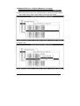
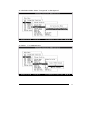
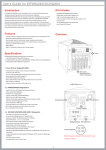
Front
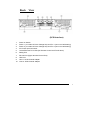
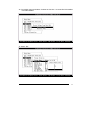
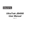
1.
RAID Subsystem
View
LED operation indicator (from top to the down)
Power on, Busy, Fault
2.
HDD LED indicator
Power on (Green), Access (Orange), Drives failure (Red)
3.
Control Button (for Controller ): “Enter”, ”ESC”, ”UP”, ”DOWN”
4.
2X16 Line LCD Display Panel
5.
6.
LOGO
Handle
User’s Manual
1
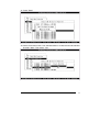
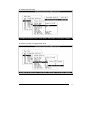
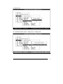
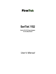
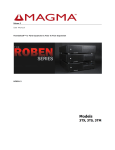
Back View
(SCSI Interface)
1.
Power on Switch
2.
Power 1 (110~260v AC Auto-Voltage Set) and Fan 1 (12x12 cm ball bearing)
3.
Power 2 (110~260v AC Auto-Voltage Set) and Fan 2 (12x12 cm ball bearing)
4.
AC Power Input Connector
5.
10/100 Ethernet RJ-45 Port (for Remote Control and E-mail alarm)
6.
Debug Port
7.
RS-232 Port (Hyper terminal Control Port)
8.
UPS Port
9. Host -1 SCSI Channel adapter
10. Host -2 SCSI Channel adapter
User’s Manual
2
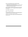
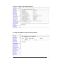
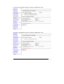
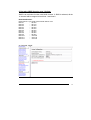
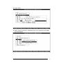
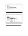
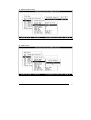
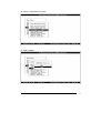
Configuration Menu Tree:
The following is an expansion of the menus in configuration Utility that can be accessed
through the LCD panel and RS-232 serial port.
Please note: The RAID subsystem controller default Password is “0000”.
Main Menus
Quick Volume/Raid Setup
Raid Set Function
Create Raid Set
Delete Raid Set
Expand Raid Set
Activate Raid Set
Create Hot Spare
Delete Hot Spare
Raid Set Information
Volume Set Function
Create Volume Set
Delete Volume Set
Modify Volume Set
Check Volume Set Consistency
Stop Volume Set Consistency
Display Volume Info.
Physical Drives
View Drive Information
Create Pass-Through Disk
Modify Pass-Through Disk
Delete Pass-Through Disk
Identify Selected Drive
Identify Bad Drive
Raid System Function
Mute the Alert Beeper
Alert Beep Setting
Change Password
JBOD/RAID Function
Raid Rebuilding Priority
Maximum ATA Mode
Terminal Port Config
Update Firmware
Restart Controller
Ethernet Configuration
Show System Events
Clear All Event Buffers
Hardware Monitor
System Information
User’s Manual
3
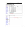
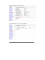
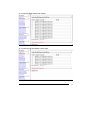
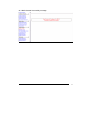
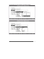
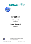
LCD Configuration Utility Main Menu Options:
Select an option and the related information or submenu items display beneath it. The
submenus for each item are explained on the section 4.7.3 of the Main Menu. The
configuration utility main menu options are:
Option
Quick Volume And
Raid Set Setup
Raid Set Functions
Volume Set Functions
Description
Create a default configurations which are based on the
number of physical disk installed
Create a customized raid set
Create a customized volume set
Physical Drive
Functions
Raid System
Functions
Views System Events
Clear Event Buffer
View individual disk information
Record all system events in the buffer
Clear all event buffer information
Hardware Monitor
System Information
Show all system environment status
View the controller information
Setting the raid system configurations
User’s Manual
4
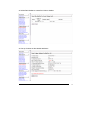
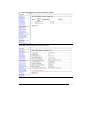
CONTENTS
Chapter 1:
1.1 System Main Feature ………………………………………
1.2 System Specifications………………………………………
page 6
page 6
1.3
page 6
System Advantage ………………………………………..
1.4. System Architecture …………………………………………
page 7
Chapter 2:
2.1 Package Checking …………………………………………..
2.2 Pass word …………………………………………………….
2.3 Hardware Installation………………………………………...
Step 1 Configuring SATA Drives…………………………..
Step 2 Loading Hard Disk to the Drive Tray……………….
Step 3 Connecting RAID subsystem Power………………
Step 4 Connecting RAID subsystem to HOST Computer..
Step 5 RAID Creation Method……………………………….
Method 1: LCD panel with keypad…………………….
Method 2: Serial Port connection ……………………..
Method 3: Ethernet Port Connection…………………..
Step6 Configure RAID Subsystems.....................................
Method 1: WEB Browser………………………………………
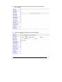
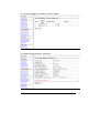
Ex. 1..
Ex. 2.
Ex. 3.
Ex 4.
Ex 5.
One single RAID-6 over 12 disk
with only one logical drive…………………………………
One single RAID-6 over 12 disks.
Cut up this RAID array into 4 logical drives (LUNs)……
Multiple RAID group over 12 disks
{Maximum 16 volume (raid group)}
Configure in three RAID groups - RAID-6 with 6 disks,
Raid-0+1 with 4 disks,JBOD with 2 disks …………………
Setting Clustering
(Redundant Server & HA software Dual Host)……….
Hot Plug JBOD over 12 disks……………………………..
Method 2: RS-232……………………………………….
Ex. 1..
page 8
Page 8
page 8
page 8
Page 8
Page 9
Page 9
Page 9
Page 9
Page 11
Page 11
Page 12
Page 12
Page 12
Page 14
Page 20
Page 24
Page 30
Page 32
Ex 4.
One single RAID-6 with over 12 disk
Page 32
with only one logical drive…………………………………
One single RAID-6 over 12 disks.
Page 34
Cut up this RAID array into 4 logical drives (LUNs)……
Multiple RAID group over 12 disks
{Maximum 16 volume (raid group)}
Configure in three RAID groups - RAID-6 with 6 disks,
Raid-0+1 with 4 disks,JBOD with 2 disks …………………… Page 41
Setting Clustering
Ex 5.
(Redundant Server & HA software Dual Host)……….
Page 51
Hot Plug JBOD over 12 disks…………………………….. Page 62
Ex. 2.
Ex. 3.
User’s Manual
5
Chapter 1:
1.1
z
z
z
z
z
z
z
z
z
z
z
z
1.2
z
z
z
z
z
z
z
z
1.3
z
z
z
z
z
z
Main Features:
Support for RAID levels 0,1,0+, 3, 5, 6 and JBOD
Host System independent
Operation System independent
High performance processor
Support On-line expanding
1GB maximum cache memory with ECC protection
Supports up to 16 logical units
Support s SCSI Host Interconnect
Supports Hot Swap, Hot Spare and Automatic or manual Rebuild
Bad Sector reassignment
Web browser-based RAID management via HTTP PROXY through Ethernet port
RAID busy, Power supply, Temperature alarm and Fan fail LED indication
Specification:
Intel IOP321 400MHz 64-bit RISC processor
1GB maximum cache memory size on one DDR200 SDRAM with ECC protection
12 Ultra ATA/133 IDE device channel, operating in parallel
Areca proprietary ASIC with polynomial engine to support RAID 6 function
12 channels 64bit/66MHz IDE controller
NVRAM for RAID configuration & transaction log
Write-through or write-back cache support
Firmware in Flash ROM for easy upgrades
Advantages:
Unique 12 bay design (Less HDD required)
System OS independent connectivity
Maximum capacity up to 2TB currently
Less down time
More features than competitors
Lower management cost:
Bootable CD VT-100 utility for X86-based system initialization
Field-upgradeable firmware in flash ROM via Ethernet or RS-232 port
Web browser-based RAID management via HTTP PROXY through Ethernet and
RS-232 port (for windows & Linux system)
Firmware-embedded manager via Ethernet and RS-232 port (platform independent)
User’s Manual
6
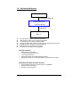
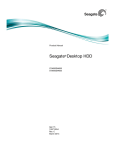
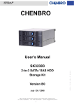
1.4
System Architecture:
Host
Ultra 320 Or Fiber 2G
RAID Subsystem
Controller Board
SATA/150
SATA/150 Drives
(Max 12)
z
z
z
z
z
z
z
Intel IOP 80321 400MHz 64-bit RISC processor
1GB maximum cache memory with ECC protection
12 channels SATA controller (133MHz/64Bit)
Areca proprietary ASIC with polynomial engine to support RAID 6 function
NVRAM for RAID configuration & transaction log
Write-through or write-back cache support
Firmware in Flash ROM for easy upgrades
Disk Bus Interface
Serial ATA/150 compatible
12 channels, operating in serial
12 hot-swap drive trays
48-bit LBA support allows disk exceeding 137GB
Staggering the Spin-Up of individual Disk to solve the power-on surge
SCSI-RAID-SATA/IDE Host Bus Interface
Ultra 320-Wide LVD SCSI; Transfer rate up to 320MB/sec
Tagged Command Queuing
Concurrent I/O commands
User’s Manual
7
Chapter 2:
2.1 Package Checking
The RAID subsystem may have included the following items in the ship package:
• RAID subsystem
• SCSI cable to interconnect the RAID subsystem*2
• Hardware terminator (SCSI-to-SATA/IDE)*2
• User manual
• Serial communications null-modem cable (RS-232 cable)
• 36 screws
2.2 Password
The RAID subsystem controller default Password is “0000” on terminal mode.
The RAID subsystem controller default User Name is “admin” and the Password is
“0000” on Web base mode.
2.3 Hardware Installation
Step 1 Configuring SATA Drives
Each SATA drive installing in the RAID subsystem which does not configured as a
“master” or “slave’ drive for your system.
Step 2 Loading Hard Disk to the Drive Tray
The RAID subsystem supports 12 Serial ATA/150 IDE channels. Each channel can run up
to 150MB/S.
1.
2.
3.
4.
5.
6.
7.
Gently take out the drive trays from the RAID subsystem by pulling out on the lever.
Remove the tray blank from hot-swap tray.
Attach the drive trays power cable to the disk drive first, and carefully push drive
trays data cable to the disk drive. Those connectors are keyed and will only fit one
way. Make sure the connectors are firmly seated; secure the drive to the hot-swap
tray with #6X3 screws.
After all drives are in the drive tray, place all of them back into the RAID subsystem.
Making sure lever is at 180-degree angle from the RAID subsystem. This is
Important so that it does not damage the hot-swap trays.
Make sure you let the lever engage by itself.
Give a final push of the drive tray to make sure it is seated firmly into the back plane.
Once it is seated firmly, click the lever in place.
Step 3 Connecting RAID subsystem Power
Connect power cord to the power connector on the rear side of the RAID subsystem
User’s Manual
8
Step 4 Connecting RAID subsystem to HOST Computer
a.
b.
Plug the Ultra 320 LVD external cable supplied with the RAID subsystem to the SCSI
adapter external connector and its SCSI-IN connector.
Add the Ultra 320 LVD external cable supplied with the other SCSI device to RAID
subsystem SCSI OUT connector. The end of the SCSI bus farthest from its SCSI
OUT must have a hardware terminator installed.
Note: SCSI Termination: All SCSI buses require termination on both ends of the bus to
prevent signal degradation. Most SCSI card supplies the termination on the origination
end of the SCSI bus. Termination is for the opposite end if the bus is provided by the
hardware terminator.
Step 5 RAID Creation Method
Method 1: LCD Panel with Keypad
The LCD status panel informs you of the Disk Array's current operating status at a glance.
For additional information on using the LCD panel and keypad to configure the RAID
subsystem see ‘LCD Configuration” on Main manual Chapter 4.
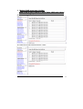
Note: There are a variety of failure conditions that cause the RAID subsystem monitoring
LED to light. Table1-1 and Table 1-2 provide a summary of the front panel LED and
RAID subsystem LED.
User’s Manual
9
LED
Power LED
Access
Fault
Normal Status
Bright Green
Problem Indication
This LED does not light up after
power switched on
Blink green during host computer LED never flickers
accessing the RAID subsystem.
LED never light up
This LED will blink amber if there is
any error action.
Table 1-1
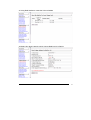
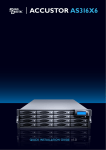
1.
LED operation indicator
(from top to the down)
Power on, Busy, Fault
2. Control Button (for controller)
3. LCD Display Panel
Disk status
Power
Activity
Drive Fail
LED
Bright Green
This LED blinks during hard drive read and
write activity.
Bright Green and RED
Bright RED
Table 1-2
Method 2: Serial Port Connection
The RAID subsystem can be configured via a VT-100 compatible terminal or a PC running
a VT-100 terminal emulation program. The provided interface cable converts the RS232
User’s Manual
10
signal connector on the RAID subsystem into a 9-pin D-Sub male connector. You can
attach a serial (Character-Based) terminal or server com port to the RAID subsystem for
access to the text-based Setup Menu. The following setup is connecting the server com
port to the RAID subsystem for access to the text-based Setup Menu
Connect external RS232 cable supplied with the raid subsystem to the host system serial
port.
Method 3: Ethernet Port Connection
The RAID subsystem can be configured via a network compatible by DHCP Server and a
PC running Browser emulation program. The provided interface cable converts the RJ-45
signal connector on the RAID subsystem into an 8-pin female connector. You can get IP
address from DHCP Server, and use server LAN port to connect with the RAID subsystem
for access to the web-based Setup Menu.
Connect external network cable supplied with the raid subsystem to the host system
RJ-45 Ethernet port.
Step 6 Configure RAID Subsystems
You can configure RAID subsystem either through the LCD Configuration utility or
Ethernet port or RS232C out of band management utility. The RAID subsystem supports
11
User’s Manual
VT-100 terminal or CD-ROM bootable VT-100 utility and Web-browser management
through the Ethernet port. In this quick set up manual will introduce you two configuration
utility, one is Web browser and the other is RS 232C. These two configuration utilities are
highly recommended to use.
The following examples are some setting for RAID configuration which will be introduced
in this quick setting book, and next part of content will explain how to achieve each setting.
Ex. 1. One single RAID-6 RAID set over 12 disks with only one logical drive.
Ex. 2. One single RAID-6 RAID set over 12 disks. Cut up this RAID array into 4
logical drives (LUNs).
Ex. 3. Multiple RAID group over 12 disks {Maximum 16 volume (raid group)}
Configure in three RAID groups - RAID-6 with 6 disks, RAID-1 with 4 disks,
and JBOD with 2 disks
Ex. 4. Setting Clustering (Redundant Server & HA software Dual Host).
R6 with 6 disks (volume 0 and 1); R5 with 6 disks (volume 2 and 3)
Volume-0 (Slice-0) for Database Index, mapped to both two Hosts.
Volume-1 (Slice-1) for Database Data, mapped to both two Hosts.
Volume-2 (Slice-2) for local data to Host-A (1), mapped to Host-A (1) only.
Volume-3 (Slice-3) for local data to Host-B (2), mapped to Host-B (2) only
Ex. 5. Hot Plug JBOD over 12 disks
Method 1: WEB Browser
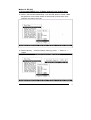
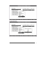
1. One single RAID-6 over 12 disks with only one logical drive.
Quickly create a Raid set–(based on current number of drives in the subsystem)
and synchronously quick create a Volume set, as well.
User’s Manual
12
User’s Manual
13
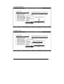
2. One single RAID-6 over 12 disks. Cut up this RAID array into 4
logical drives (LUNs).
2a. Create a Raid Set#00 over 12 disks
2b. Raid Set Created Successfully message
User’s Manual
14
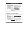
2c.Utilize Raid Set#00 to create first Volume Set#00
2d. Set up Volume set #00 default attributes
User’s Manual
15
2e. Set up completed and the screen will show ”Volume Set Created
Successfully”
2f. Using Raid Set#00 to create second Volume Set#01
User’s Manual
16
2g. Set up Volume set #01 default attributes
2h. Using Raid Set#00 to create third Volume Set#02
User’s Manual
17
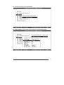
2i. Set up Volume set #02 default attributes
2j. Using Raid Set#00 to create forth Volume Set#03
User’s Manual
18
2k. Set up Volume set #03 default attributes
User’s Manual
19
3. Multiple RAID group over 12 disks
RAID-6 with 6 disks, RAID-0+1 with 4 disks, JBOD with 2 disks
The total Raid group can be slice into maximum 16 volumes
3a. Create first RAID Set #00 with 6 disks
3b.Create the second Raid Set #01with 4 disks
User’s Manual
20
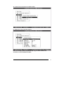
3c.Using Raid Set#00 to create the Volume Set#00
3d.Setting four disks’ capacity which Volume Raid level is in Raid 6
User’s Manual
21
3e.Using Raid Set#01 to Create Volume Set#01
3f. Setting the capacity of 4 disks which Volume Raid level are in Raid 0+1
User’s Manual
22
3g. Using “Create Pass through” to create the JBOD with 1 disk
3h. Using “Create Pass through” to create the JBOD with 1 disk
User’s Manual
23
3i. Click ”Raid Set Hierarchy” to view the Subsystem configuration
4. Setting Clustering (Redundant Server & HA software Dual Host).
R6 with 6 disks (volume 0 and 1); R5 with 6 disks (volume 2 and 3)
Volume-0(Slice-0) for Database Index, mapped to both two Hosts.
Volume-1(Slice-1) for Database Data, mapped to both two Hosts.
Volume-2(Slice-2) for local data to Host-A(1), mapped to Host-A(1) only.
Volume-3(Slice-3) for local data to Host-B(2), mapped to Host-B(2) only.
User’s Manual
24
4a. Create first Raid Set#00 with 6 disks
4b. Create second Raid Set#01 with 6 disks
User’s Manual
25
4c. Using Raid Set#00 to create the Volume Set#00
4d. Setting SCSI Channel on “0&1 for cluster”
User’s Manual
26
4e. Using Raid Set#00 to create the Volume Set#01
4f. Setting SCSI Channel on “0&1 for cluster”
User’s Manual
27
4g. Using Raid Set#01 to create the Volume Set#03
4h. Setting SCSI Channel on “Channel 0”
User’s Manual
28
4i. Using Raid Set#01 to create the Volume Set#04
4j. Setting SCSI Channel on ”Channel 1”
User’s Manual
29
5. Hot-plug JBOD function over 12 disks
JBOD is an exclusive function with RAID function. If JBOD is selected, all the
12 channel will be mapped to both host 1 and host 2.
Disk Identification:
DISK Channel – Host SCSI Channel\SCSI ID\SCSI LUN
IDE Ch1
-- 0&1/0/0
IDE Ch2
-- 0&1/1/0
IDE Ch3
-- 0&1/2/0
IDE Ch4
-- 0&1/3/0
IDE Ch5
-- 0&1/4/0
IDE Ch6
-- 0&1/5/0
IDE Ch7
-- 0&1/6/0
IDE Ch8
-- 0&1/8/0
IDE Ch9
-- 0&1/9/0
IDE Ch10
-- 0&1/10/0
IDE Ch11
-- 0&1/11/0
IDE Ch12
-- 0&1/12/0
5a. Selected “JBOD”
User’s Manual
30
5b. JBOD Created Successfully message
User’s Manual
31
Method 2: RS-232
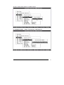
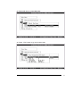
1. One single RAID-6 over 12 disks with only one logical drive.
1a. Select “ Quick Volume/Raid Setup “ from the Main Menu to create a Raid
set–(based on current total number of drives) and synchronously quick
configure the Volume set in R6
1b. Select Capacity: to adjust capacity setting by press “ ↓”button or “↑”
button
User’s Manual
32
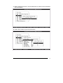
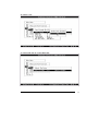
1c. Select Stripe Size
1d. Select “ YES”
User’s Manual
33
1e. Initialization Mode: select ” Foreground” or “Background”
Foreground init:
The initialization proceeds must be completed before the volume set ready for system
accesses.
Background init:
the initialization proceeds as a background task, the volume set is fully accessible for
system reads and writes. The operating system can instantly access to the newly created
arrays without requiring a reboot and waiting the initialization
“One single RAID-6 over 12 disks” has been successful completed
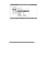
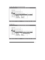
2. One single RAID-6 over 12 disks. Cut up this RAID array into 4
logical drives (LUNs).
2a. Select “ Quick Volume/Raid Setup “ from the Main Menu to create a Raid
set#00–(based on current total number of drives) and synchronously quick
configure the Volume set in R6. Then, select capacity for the first Volume
(#00).
User’s Manual
34
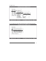
2b. Select Stripe Size
User’s Manual
35
2c. Select “Yes”
2d. Initialization Mode: select ” Foreground” or “Background”
User’s Manual
36
2e. Create Volume#01 from Raid Set#00
2f. Select Capacity. Then, press “ ESC” button to go to the next screen
User’s Manual
37
2g. Create Volume: Select “ Yes”
2h. Initialization Mode: select ” Foreground” or “Background”
User’s Manual
38
2i. Create third Volume#02 from Raid Set#00
2j. Setting the Volume set #02 capacity
The rest of steps, please repeat the step “2g”to create Volume set
and”2h”to select Initialization Mode
User’s Manual
39
2k. Create forth Volume#03 from Raid Set#00
2l. Setting the Volume set #03 capacity
The rest of steps, please repeat the step “2g”to create Volume set
and”2h”to select Initialization Mode
User’s Manual
40
3. Multiple RAID over 12 disks (Maximum 16 arrays)
RAID-6 with 6 disks, RAID-0+1 with 4 disks, JBOD with 2 disks
3a. Select “Raid set function” from the Main Menu to create first RAID Set #00
with 4 disks. Then, press “ ESC” button to go to the next screen
3b. Select “Yes”
User’s Manual
41
3c. Press ”Enter”
3d. Select “Raid set function” from the Main Menu to create the second Raid Set
#01with 2 disks. Then select “Yes”.
User’s Manual
42
3e. Press “Enter”
3f. Select “Volume set function” Main Menu from the to create first Volume#00
from Raid Set#00
User’s Manual
43
3g. Select Raid Level: setting the RAID 6 in the Raid level attribute
User’s Manual
44
3h.Then, press “ESC” button to “Create Volume”
3i. Initialization Mode: Select ” Foreground” or “Background”
User’s Manual
45
3j. Select “Volume set function” from the Main Menu to create second Volume#01
from Raid Set#01
3k. Press “ ESC” button to go to the next screen
User’s Manual
46
User’s Manual
47
3l. Select ”Yes”
3m. Go to Main menu and select “Physical drive” to create pass-through disk
User’s Manual
48
3n. Select IDE disk to create JBOD disk
3o. Press “ ESC” button to go to the next screen
User’s Manual
49
3p. Select “Yes”
3q. Select IDE disk to create JBOD disk
User’s Manual
50
3r. Press “ ESC” button to go to the next screen
3s. Select “Yes”
User’s Manual
51
4.Setting Clustering (Redundant Server & HA software Dual Host).
R6 with 6 disks (volume 0 and 1); R5 with 6 disks (volume 2 and 3)
Volume-0 (Slice-0) for Database Index, mapped to both two Hosts.
Volume-1 (Slice-1) for Database Data, mapped to both two Hosts.
Volume-2 (Slice-2) for local data to Host-A(1), mapped to Host-A(1) only.
Volume-3 (Slice-3) for local data to Host-B(2), mapped to Host-B(2) only.
4a. Go to Main Menu and select “Raid set function” to create first RAID Set #00
with 4 disks. Then select “Yes”
4b. Press “Enter”
User’s Manual
52
User’s Manual
53
4c. Go to Main Menu and select “Raid set function” to create the second
Raid Set #01with 4 disks. Then select “Yes”.
4d. Press “Enter”
User’s Manual
54
4e. Go to Main menu and select “Volume set function “ to create first Volume#00
from Raid Set#00
4f. Select “R6”
User’s Manual
55
4g. Select Capacity Size
4h. Select” Cluster” to mapped both host
User’s Manual
56
4i. Select “Yes”
4k. Initialization Mode: Select ” Foreground” or “Background”
User’s Manual
57
4l. Go to Main menu and select “Volume set function” to create second
Volume#01 from Raid Set#00
4m. Select “R6”
User’s Manual
58
4n. Select” Cluster” to map both host
4o. Select “Yes”
User’s Manual
59
4p. Initialization Mode: Select ” Foreground” or “Background”
4q. Go to Main menu and select “Volume set function” to create third Volume#03
from Raid Set#01
User’s Manual
60
4r. Select Capacity Size
4s. Select “Yes”
User’s Manual
61
4t. Initialization Mode: Select ” Foreground” or “Background”
4u. Select ”1” to mapped host 1
User’s Manual
62
4v. Select “Yes”
4w. Initialization Mode: Select ” Foreground” or “Background”
User’s Manual
63
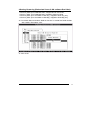
5.Hot-plug JBOD function over 12 disks
(If JBOD will coexist with Multiple RAID, please reference example 3)
JBOD is an exclusive function with RAID function. If JBOD is selected, all the
12 channels will be mapped to both host 1 and host 2.
Disk Identification:
DISK Channel – Host SCSI Channel\SCSI ID\SCSI LUN
IDE Ch1
-- 0&1/0/0
IDE Ch2
-- 0&1/1/0
IDE Ch3
-- 0&1/2/0
IDE Ch4
-- 0&1/3/0
IDE Ch5
-- 0&1/4/0
IDE Ch6
-- 0&1/5/0
IDE Ch7
-- 0&1/6/0
IDE Ch8
-- 0&1/8/0
IDE Ch9
-- 0&1/9/0
IDE Ch10
-- 0&1/10/0
IDE Ch11
-- 0&1/11/0
IDE Ch12
-- 0&1/12/0
5a. Select “Raid System function” from Main Menu
User’s Manual
64
5b. Select “ JBOD/RAID Function”
5c. Select “JBOD”
User’s Manual
65
5d. Press “Enter”
User’s Manual
66